Superior Tube Company. Tube Crop and Deburr Process Improvement. Phase 4
|
|
|
- Annabel Simmons
- 5 years ago
- Views:
Transcription
1 Superior Tube Company Tube Crop and Deburr Process Improvement Phase 4 Senior Design Fall 2010 Joshua Blechman Thomas Daddario William Ogram Matthew Ward
2 2 Table of Contents pg. # I. Customer Description 3 II. Identification of Needs and Wants 6 III. Constraints 8 IV. Project Scope 8 V. Metrics 9 VI. Alternative Concepts 9 A. Automation 9 B. Shear Cutter 10 C. Cutting Blades 10 VII. Deburring Tool 11 A. Design Overview 11 B. Motivation 11 C. Design Details 11 D. Design Verification 15 E. Path Forward 18 VIII. Reusable Nylon Bundle Ties 20 A. Design Overview 20 B. Motivation 21 C. Design Verification 21 D. Path forward 24 IX. Concluding Remarks 25 X. Appendices 26 A. Drawing Package 26 B. Prototype and Testing Images 36
3 3 I. Customer Superior Tube Company Superior Tube Company manufactures tubes in a wide range of sizes and alloys. Tubes are custom fabricated for over 1000 outer diameters ranging from and numerous wall thicknesses. Materials processed range substantially; with the hardest being a work-hardened 718 alloy and the softest being nickel 200. There are fifty plus different alloys in between these book ends of various strengths and mechanical properties. The general process flow is illustrated on the following page. Tubes are drawn over a mandrill to a specified size. Afterwards they are transported to a cropping station. Currently cropping is performed by a single operator using an abrasive radial saw. Cropping is necessary at this stage because the ends of the tubes are clamped during the drawing process and these pinched off ends must be removed prior to degreasing. If they are not removed there will be excessive grease clogging up the system and the tubes will be unfit for future processing. The degreasing step involves submerging the tubes in a solvent to remove the 201 lubricant or plastic superkote that had been previously applied to the tube prior to drawing. Once the tubes are cropped and degreased they are moved to a reaming, deburring, and blow out station. Here a single operator manually feeds the tubes onto the deburring machine to remove any burrs that could be problematic in future processing. The operator must then blow out the tubes individually with a pressurized air gun to remove any debris. For specific orders, cloth wads are inserted into one of the tube prior to blow out to maximize debris removal. Burrs and debris that are not properly removed can lead to the development of tube defects. At this point, tubes can take one of two different paths. Commonly tubes are sent to be annealed and then sent through the entire process over again starting at drawing. Typical batches experience the drawing, cropping, deburring, and annealing cycle 5-10 times before they reach the desired size. Once this proper sizing is achieved tubes are sent out for post processing, finishing, and evaluation.

 Storage/Transport")
 Cropping")


4 4 Input Intermediate Processing (Annealing, Drawing, etc.) Storage/Transport (Tubes greased, ends clamped) Cropping Storage/Transport Storage/Transport (Tubes greased, edges rough) Inner and Outer Tube Deburring and Blow out Storage/Transport (Edges rough) Degreasing Storage/Transport Post Processing (Finishing, Error Correction, etc.) Output
5 5 The current set ups for both the cropping and deburring stations are illustrated below. Cropping Station (left), R&D Station (Right); dimensions approximate At the cropping station, the operator feeds tubes along the rollers until they line up appropriately with the saw. Generally this is not a precise operation and the primary goal is to cut off the clamped ends. Otherwise, stoppers are positioned so that the tubes can be pushed up against the stopper and then cut to the desired length. Tubes are stored pre and post cropping on the marked tables. At the deburring station a single operator feeds the tubes, one end and one tube at a time, onto the reaming and deburring tool heads. They must then walk around to the other side of the table and ream and deburr the opposite end of the tube. The tubes are then rolled over to the far side of the table to be blown out. Between each processing step the tubes must be transported and stored. Overhead trolleys are used for moving larger batches of tubes. Storage and materials handling comprise a large portion of each tubes manufacturing life.
6 6 II. Customer Needs/Wants The needs/wants of the customer are focused on the cropping/reaming/deburring/blowout processes and include the following: Increased process productivity Reduced process cost Increased system efficiency Decreased rate of defects Minimize room for operator error, increase user friendliness Combining multiple steps of the process into a single step In order to get a better idea for the needs of the system we performed a time study in early September. This involved monitoring operators working at both the cropping and deburring s stations and recording the time spent performing each little task. In addition, the study provided a baseline figure for the production rate of the current process. The results are summarized in the following tables: Cropping Production Rate 150- tubes/hr. 200 Time Breakdown Task Cutting Preparation Upkeep % of Total Time Ream/Deburr/Blow Out Production Rate 100 tubes/hr. Time Breakdown Task R/D Blow Out Wadding Preparation % of Total Time These figures will be used as references when evaluating the perceived benefit of any proposed system improvement. In addition to revealing baseline statistics about Superior Tube s processes, this study also highlighted the significance of tube preparation and handling time. In addition to the research above, a value stream map was filled out for the processes to break down the allotment of time to each task and show key areas for improvement. The results are summarized in the following table:
7 7 Value Stream Mapping for Tube Cutoff/Ream/Deburr/Blowout Task Value Adding Task Time (seconds) Time since last task completed Movement 1. Cropping 0-3 days Carrying with crane/waiting a. Unbundle tubes No 30 Untying ropes b. Gather Handful of tubes No 15 Gather tubes c. Align tubes No 10 Push tubes against flat surface d. Cut ends off Yes 15 Use abrasive saw e. Move to other end No 10 Slide tubes f. Align tubes No 10 Push tubes against flat surface g. Cut end off Yes 15 Use abrasive saw h. Move to finished area No 10 Slide tubes i. Bundle Tubes No 60 Tie ropes around bundles 2. Degreasing Yes 0-3 days Carrying with crane/waiting 3. Ream/Deburr/Blowout 0-3 days Carrying with crane/waiting a. Unbundle tubes No 30 Untying ropes b. Lay tubes on table No 10 Roll tubes c. Turn on machine No 5 Flip switch d. Ream tubes Yes 10/tube Press tube on tool e. Deburr tubes Yes 10/tube Press tube on tool f. Turn off machine No 5 Flip switch g. Move to other end No 10 Slide tubes h. Align tubes No 10 Roll tubes i. Turn on machine No 5 Flip switch j. Ream tubes Yes 10/tube Press tube on tool k. Deburr Tubes Yes 10/tube Press tube on tool l. Turn off machine No 5 Flip switch m. Wad tubes (optional) No 10/tube Put wads inside tube n. Blowout tubes Yes 10/tube Place air nozzle in tube o. Bundle tubes No 60 Tie ropes around bundles This is a Value Stream Mapping for the process. It includes each step performed in the process, whether or not the step adds value to the product, the time of each step, and the time between each step. Highlighted in this table are the tasks with longer step times which are the focus for improvements. The greatest time delays occur between processes where tubes are sitting around waiting to move along in the system. The longest individual times include bundling and unbundling tubes in each process. The long times per tube processed includes reaming each tube, deburring each tube, and blowing out the chips in each tube. Overall, this table provides insight into where waste occurs in the process.
8 8 III. Constraints The following constraints were imposed upon us by Superior Tube Investments must pay for themselves within ~ 2 years Available space is limited by the current factory setup Must be compatible with process flow Time IV. Project Scope The goal of this project was to enhance the processes at Superior Tube, with a specific focus on tube cropping, reaming, deburring, and blow out. The current system was observed and evaluated to determine areas in need of improvement. Tube degreasing became a prohibitive step that made the combination of processes into a single workstation unfeasible. As a result, the cropping station and deburring station were examined as separate, although related, entities. At this point we considered several possibilities. We looked into automation but it did not appear viable for the costs due to Superior s small production quantities and variability in tube sizing. Alternative cutting options were also evaluated but were found to be either prohibitively expensive due to the need for a die for each tubing size or marginal improvements not worthy of an investment. The focus of our project became improving the deburring process. A tool was designed with the capability to simultaneously remove burrs from the inner and outer diameters of tubing while rapidly adjusting to the desired sizing. Additionally, we noticed an abundance of non-value adding material handling steps. To reduce this waste we examined the benefits of transitioning from rope ties to reusable cable ties.
9 9 V. Key Performance and Cost Metrics The following were determined to be important performance metrics: Process time includes cutting, reaming, deburring, blow out, and time between processes Process cost includes cost for each process listed above Quality diameter and length compatibility as well as defect rate Essentially the primary metric will be to upgrade the process so that it is more cost effective. Quality and time metrics are important mainly because of how they relate to cost and productivity. System updates will be evaluated based on their ability to produce economic gains for superior tube, whether it be through reductions in cost or increases in productivity. VI. Alternative Concepts A. Automation Original Phase I designs were based on streamlining the cropping and reaming/deburring stations into one process. The cropping station would be connected directly to a reaming and deburring station, which would theoretically eliminate the transportation requirement between the two stations. As designs were developed, the idea of automating the process was highly encouraged. Eliminating an operator would allow the company to save money in the long run. Currently, the process uses a different operator for each station, as well as additional operators for the transportation between stations. However, it was revealed after Phase I that none of these concepts would be possible. This was due to the Degreasing step that must occur between the two steps. Degreasing cannot occur before the tube ends are cut off because of the one pinched end of the tube created during pultrusion. Operators would also not want to work with greasy tubes during the reaming and deburring of the tubes. Therefore, it was not possible to streamline the process, which made the main ideas of the initial concepts obsolete. Automating a single station does not seem cost effective due to the large variety of tube sizes that are manufactured at Superior Tube. With limited space, it would not be possible to come up with different automations for separate processes. It is recommended that if automation is to be considered in the future, the entire tube manufacturing process should be reevaluated. This senior design process was limited by the number of stations which could be evaluated and changed.
10 10 B. Shear Cutter While researching different cutoff methods, a shear cutting tool was found to be one of the possibilities that could replace the current saw. The tool would be able to cut off a tube without leaving any burrs in the cutoff area. This would have been highly beneficial because it would have eliminated the entire reaming and deburring station. Eliminating this station would also eliminate an operator, and free up some space in the factory. The drawbacks of this device were that it could only handle one tube at a time, and it would require a separate die for each different diameter tube. The current cutoff method has an operator cut a whole bundle of tubes at once. However, if it could in fact eliminate the reaming/deburring process, it still seemed like a great replacement tool. After some collaboration with the sponsor, it was found that there were a thousand different outer diameters that the tubes could have. Each of those sizes would require a different die, so the implementation of this machine quickly became unlikely. It would be extremely expensive to buy the machine and a thousand different dies. The dies would have to be changed between each process, and new storage would be required for such a large number of dies. With limited space and budget, the device was ruled to be outside of our parameters and was thrown out. C. Cutting Blades The current abrasive saw uses aluminum oxide discs, which have a low life and need to be replaced frequently. These disks can be replaced with other abrasives that are harder such as silicon carbide, or even cubic boron nitride. The harder discs will have a longer life and will not need to be replaced as frequently. Although other abrasives are harder, it is common in cutting steels to use aluminum oxide as silicon carbide has a tendency to chip when cutting steel and can result in an uneven cut. A cubic boron nitride disc will cost roughly times as much as an aluminum oxide disc and the life of this disc is not long enough to justify that cost. Also the harder discs need to be run at a lower speed than the aluminum oxide discs, and the current abrasive saw used at Superior Tube can only run at this high speed set for aluminum oxide. A new abrasive saw will need to be purchased in order to run these harder discs at a lower speed. The quality of the cut of an aluminum oxide disc is about the same as with a harder disc. Therefore it is not cost effective to change the current abrasive discs used.
11 11 VII. Deburring Tool A. Design Overview Currently, the deburring station involves two tool heads that each tube must encounter. The first is to take off burrs on the outside of the tube (deburr), and the second tube takes off burrs within the inside of the tube (ream). This combined tool head will condense this 2 step process into 1. The spring loaded feature allows for it to accommodate a range of tubes from 0.25 to 1.5 inner diameter. High speed steel blades are used to cut and handle a wide range of materials that Superior Tube deals with on a daily basis. B. Motivation The deburring tool is focused on streamlining the current Ream and Deburr process at Superior Tube. Due to Superior s wide range of custom tubing both in ID/OD and material selection a tool head that would be able to ream and deburr a majority of them without any change would be very advantageous. A combined tool head specifically would help streamline the station, and provide less work for the operator to do. This design specifically targets these ideas. C. Design Details The chart below lays out quantity and material used to fabricate the prototype: Part Layout Quantity Material Reaming Cone 1 Aluminum 6061 Deburr Casing 3 Aluminum 6061 Guide Tooth 2 Aluminum 6061 Blade Holding Tooth 1 Aluminum 6061 Spring (2 ID, k=10lb/in) 1 Galvanized Steel Attachment Base 1 Aluminum 6061 Attachment Rod 1 Steel 4 40 Screws 18 Steel Blades 2 High Speed Steel


12 12 Assembly Protocol: Note that it is important to follow the steps using the same views as those shown in the figures below. 1. Attach first Deburr casing to both linear guides with screws as shown: Figure 1 - Align Linear guides as shown, and screw together 2. Attach second deburr casing to right linear guide with screws: Figure 2 - Align Linear Guide with Current assembly and screw together 3. Attach Slotted Linear guide to casing from previous step, it is important that this guide is attached so that its right face is still exposed: Figure 3 - Note Right side face of slotted guide is exposed


13 13 4. Finally attach last deburr casing with tapped hole to complete Sub-Assembly 1: Figure 4 - Sub Assembly 1 now complete 5. Align Reaming cone with Sub Assembly 1 and simply drop in to complete Sub Assembly 2: Figure 5 - Clearance fit allows for easy placement 6. Align Spring and place over the bottom end of the reaming cone, align base and screw in attachment rod, complete Sub Assembly 3: Figure 6 - Sub Assembly 3


14 14 7. Place blade into reaming cone by compressing deburr casing down and tightening a set screw: Figure 7 - Hole for set screw is easily accessible by compressing deburr casing 8. Place final blade into the slotted linear guide and utilize tapped hole to tighten a set screw in place: Figure 8 - Deburr casing is not shown in right picture to show blade in place This completes assembly of the prototype. See Appendix A for complete drawing package. See Appendix B for photographic images of completed prototype.

15 15 Figure 9 - Multiple views of completed Assembly D. Testing A. Description of Procedure and Data Collection Purpose: The Aluminum prototype must be tested in order to prove that the concept is valid. The different material and lack of a proper deburring blade requires that the device be used on materials of lower strength and hardness. Materials: Fully assembled prototype PVC pipes of various diameters Aluminum pipes of various diameters Vice Hacksaw Lathe
16 16 Procedure: 1. Make sure that the prototype is fully and properly assembled. 2. Fit the prototype s bottom shaft into lathe as close to the bottom plate as possible. This will help to minimize vibrations and bending. 3. Adjust lathe to the lowest gear setting possible (82 rpm low, 163 rpm high). 4. Set the lathe to low. 5. Select PVC pipe and measure actual OD and ID range. 6. Place pipe firmly in vice so that it does not rotate. Do not tighten excessively to avoid crushing the pipe. 7. Use the hacksaw to cut off an end of the pipe. This will create burrs on the OD and ID. Remove pipe from vice when fully cut off. 8. Write down the pipe description and rpm used. Photograph the pipe with the burrs on it. Turn on the lathe. 9. Press the burred end of the pipe into the blades on the rotating prototype. Continue pressing the pipe onto the blades until all burrs are removed. 10. Remove the pipe and turn off the lathe. Record how much time the pipe was pressed on the prototype. 11. Evaluate how much difficulty the tester experienced while using the prototype and record. Use a scale of 1 to 5; 1 being not very difficult, 5 being very difficult. 12. Repeat steps 5-11 for several different pipe sizes. 13. Set the lathe to high and repeat steps Repeat steps 5-12, but for aluminum pipe.
17 17 B. Results and Analysis: Description RPM Operator difficulty Time OD OD ID ID min max min max 1.25 PVC PVC PVC PVC PVC PVC PVC PVC PVC PVC Aluminum Comparing the low rpm to high rpm, it is clear that it takes less time to fully remove the burrs on a higher rpm. The testers also had a much easier time in using the device when it was spinning at the higher rpm. PVC pipes are clearly easier to work with, and its burrs are much more apparent when present. This represents a larger scale version of how the actual device would work on stainless steel, thin walled tubes. The prototype created a chamfer on the inner and outer diameters of the pipes which completely removed all burrs from those areas. This is exactly what the concept is designed to do. Aluminum pipes give a better idea of how the device will handle a metal. However, aluminum cannot be attained in thin walled form, so it is on a slightly larger scale than the stainless steel tubes. The prototype successfully removed all burrs from all test samples in a reasonable time. Operators experienced a low amount of difficulty in using the device, which seemed to decrease for higher speeds. These tests prove that the prototype is capable of being used on many different size pipes and pipes of different materials. See Appendix B for photographic images from testing.
18 18 E. Path Forward Updated Design and Manufacturing Modifications The performance of the prototype was promising but also revealed opportunities for design improvements. If Superior wishes to move forward on this idea we recommend the following modifications to the prototype design. These changes will increase the quality and consistency of the tools performance as well as make the device more user friendly to operate. Prototype to Design Materials Update: The prototype was manufactured from aluminum; however the final tool will be manufactured from steel and will utilize the same cutting blades as the deburring tools currently in use at Superior. This will give it the structural and cutting capability to perform on the wide range of alloys that it will encounter. Wire EDM Forming of the Deburring Casing: In order to increase the precision and integrity of the design we recommend that the deburring case be machined as a single part from stainless steel using wire EDM technology. Wire EDM will allow for the intricate internal geometry to be machined directly. In the prototype, the deburring casing was broken into 3 sections and the components were attached with screws through the guide teeth. In the updated design the three teeth and three pieces of the deburring casing will be combined into a single steel piece, also removing the need for 18 screws and simplifying the assembly process tremendously. The single part casing constructed via wire EDM will allow for a more ideal geometry to be realized without the slop and difficulties that arise from a part with a high number of components. The actual wire EDM job will be outsourced to a company who specializes in the field. The following is the web address to a list of 40 vendors who offer EDM services:
19 19 Reducing Chatter: The prototype was observed to have considerable chatter. The slip fits used in several interfaces throughout the tool create slop which allows the various components to tilt and slide relative to one another. This movement decreases the quality of the alignment of the tubes and the cutting surfaces. In order to improve the design we recommend the incorporation of linear guide blocks to control the movement of the deburring casing relative to the inner reaming cone. Position Control: The spring for the prototype was intended for testing purposes and was formed manually using steel wire. The updated design will include a specifically designed spring. Custom springs can be obtained from the following website: Based on our experiences working with the prototype, we recommend a spring force of 10 lbs/in. This will provide the resistance required while minimizing the strain on the operator. The addition of a set screw will provide additional control by giving operator the option to lock the device in the position desired. The set screw will work in conjunction with the linear guide block. Tightening the screw will secure the guide block in place, allowing the operator to deburr tubes of a given size without having to apply the force necessary to overcome the spring. Another advantage of a set screw to lock the position of the tool is that it will generate a consistent cut over an entire batch of tubes.

20 20 VIII. Reusable Nylon Bundle Ties A. Design Overview For small diameter production batches, which are particularly susceptible to bending, ropes are used to tie the tubes into bundles for handling. Operators are required to tie and untie the ropes, a time investment that quickly adds up when each bundle is tied by two to four ropes. By converting to releasable nylon cable ties the time required to bundle and debundle tubes can be reduced considerably. Nylon is resilient enough to withstand both the physical wear and tear of processing as well as the corrosive chemical environment present during the necessary degreasing steps. The nylon ties will last much longer than the ropes currently being used, which wear over time and are frequently discarded.
21 21 B. Motivation Tube preparation and tube handling accounts for approximately 40% of the total processing time spent at the deburring and blow out station. This percentage is significantly higher for batches that do not require wadding. Much of this time is spent debundling tubes to prepare them for processing or repacking tubes into bundles for post processing storage. Transitioning from hand tied ropes to reusable cable ties will make the bundling and debundling tasks much quicker and more efficient. Tube handling is not a value adding process so anything that can be done to reduce the time and energy spent on it is beneficial to the overall system. Furthermore, rope ties are inconsistent, varying from operator to operator. The nylon ties will bring increased consistency and repeatability. C. Design Verification i. Testing: Procedures and Data Cable Ties Time Study: Time trials were performed using three operators. First, the operators were familiarized with the cable ties and allowed to practice with them until proficiency. Five practice runs were typically sufficient for the operator to drop down to a consistent pace. Next the operator was timed for how long it takes them to apply and remove the cable tie. Since no tubes were available, a cylinder of approximately the same diameter was used. To better simulate the difficulty of tying actual tubes a handle was attached through which the ties must be threaded. Ten trials were performed for each operator and the results are summarized in the table below. Operator 1 Operator 2 Operator 3 Trial # Bundling De-Bundling Bundling De-Bundling Bundling De-Bundling Avg


22 22 Rope Ties Time Study: Two operators were observed and timed while performing the rope tying operation. Operator A was familiar with the task while operator B was just introduced to the task, but given time to learn the fundamentals before being timed. The times required for them to tie the ropes are summarized in the following table. Operator A Operator B Trial # Bundling Bundling Avg The images below depict the traditional rope ties and the reusable nylon ties as they would be in use.
23 23 ii. Results and Analysis The important results of the time studies are summarized in the table below. Rope Ties, Average Time to Bundle (s) 10 Nylon Ties, Average Time to Bundle (s) 4.63 Quantitative Time Savings, per Tie (s) 5.37 Percentage Time Savings, per Tie 54% The cable ties cut the bundling time by 54%, or to less than half of its original value. This is a very significant improvement. Each bundle typically has between two and four ties on it. Furthermore, each tube undergoes a great many bundling and debundling operations throughout its factory life. The time gains achieved throughout the process will quickly add up. Based on our process observations from September, it can be estimated that tubes are processed at a rate of 8 bundles per hour, with each bundle requiring an average of three ties. The value of this result is summarized in the following table. Time savings (seconds/tie) 5.37 Bundles/Hour 8 Ties/Bundle 3 Time Savings (seconds/hour) 129 Productivity increase 3.6% Operator cost savings ($/hour) 0.72 Based on conservative estimate which do not even taken into account the reduced time needed to debundle tubes tied by cables versus ropes, the cable ties will increase productivity by 3.6%. This equates to $0.72/hour savings in operator costs based on a worker salary of $20.00/hour. These figures are not tremendous, but, considering the simplicity and ease with which the transition could be made, they are enough to demonstrate the validity of the design. An additional benefit of the cables ties is that they will bring consistency and repeatability to the tying and handling of bundles. When it comes to using ropes, the individual operator determines what type of knot will be tied. Although most follow a general pattern of rapping the rope around the tube prior to tying it there are still quite a few deviations. Using the cable ties, however, resulted in a consistent output. Furthermore, the training required to become adept with the cable ties is less than that required to achieve the same level of proficiency with the rope ties. This will be beneficial when acquainting new operators to the task.
24 24 D. Path Forward - Procurement It is recommended that Superior Tube begins a wide scale transition from rope ties to reusable nylon cable ties. This will add increased productivity and consistency throughout the tube production system. The initial investment will more than be made up for by savings in operator time and higher production rates. Once the initial investment is paid off, the ties will continue to bring consistency and economic benefit to the system for years to come. Nylon ties are available in a variety of sizes and qualities. This site has 15 ties sold in packs of 4 for $4.19. Superior Tube has already purchased a package of these ties and is performing evaluations to verify the durability of these ties when exposed to certain chemical conditions &ff4=263602_304652&viewitem=&guid=082adb4412c0a0a9f ff772ba2&hlp=false&rvr_id= &ua=%3F*F%3F&itemid= This is an example of how ties can be found in large quantities for quite cheap using sites such as EBay. Since there is a buy it now option this is not much different than ordering from any other online retailer. This site offers heavy duty 29 ties for approximately $1.00 per tie. This option offers the highest quality as well as the greatest length which allows for bundling of larger diameter tubes.
25 25 IX. Concluding Remarks While revamping the entire manufacturing system at Superior Tube was beyond the scope of this project, we were able to focus in on some key aspects of the process. The deburring tool prototype showed how a device could be constructed to simultaneously deburr both edges of tubes of varying sizes. The preliminary design, updated with knowledge gained through testing and evaluation, can be updated and fabricated for use on the factory floor. While the testing confirmed the validity of the concept, it may take some time for the economic benefits of updating and fabricating a working tool to be realized. The implementation of reusable cable ties will provide almost immediate productivity gains while reducing wasteful material handling. Due to the low cost at which the nylon ties can be obtained, their investment will quickly pay for itself. We recommend a full transition, where possible, from rope ties to cable ties. In addition, it would be worthwhile for Superior to look across their entire factory to determine how materials handling and other non-value adding steps can be streamlined to reduce waste and create a leaner manufacturing system.
26 26 X. Appendices Appendix A Drawing Package
27 27
28 28
29 29
30 30
31 31
32 32
33 33
34 34
35 35


36 36 Appendix B Prototype and Testing Images Side View of Prototype Shot of Blade Front View of Prototype


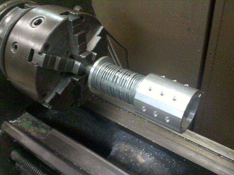
37 Prototype Chucked in Lathe 37


38 38 PVC 1.25 pre high RPM cut PVC 1.5 pre high RPM cut PVC 1.25 post high RPM cut PVC 1.5 post high RPM cut
Catalogue. Rollers for belt conveyors
 Catalogue Rollers for belt conveyors This catalogue contains a selection of the most commonly used standard rollers designed for bulk materials handling. Other sizes of rollers are available upon request.
2179-CD Series Fiber Optic Splice Closure. Installation Instructions
 2179-CD Series Fiber Optic Splice Closure Installation Instructions 1.0 Product Introduction The new 3M TM 2179-CD Series Fiber Optic Splice Closure can be used in buried, underground, aerial, and pedestal
Axle Assembly Poke-Yoke
 Indiana University Purdue University Fort Wayne Opus: Research & Creativity at IPFW Manufacturing & Construction Engineering Technology and Interior Design Senior Design Projects School of Engineering,
Cable installation guidelines
 The Quality Connection Cable installation guidelines Business Unit Industrial Projects 2 Cable installation guidelines www.leoni-industrial-projects.com GENERAL Installation methods Many different methods
5374 Series Air Activated Tube Tester (For testing straight-through exchanger without removing both heads.)
") TM-73 July 15, 2004 Elliott offers a complete line of precision tube tools, including: tube expanders Boiler Expanders Heat Exchanger Expanders Condenser Expanders Refinery Expanders tube rolling motors
TM-73 July 15, 2004 Elliott offers a complete line of precision tube tools, including: tube expanders Boiler Expanders Heat Exchanger Expanders Condenser Expanders Refinery Expanders tube rolling motors
"CHOOSING A STATIC MIXER"
 "HOW TO CHOOSE A STATIC MIXER TO PROPERLY MIX A 2-COMPONENT ADHESIVE" BY David W. Kirsch Choosing a static mixer requires more than reading a sales catalog and selecting a part number. Adhesive manufacturers
A449-6S 70 CENTIMETER FM YAGI ANTENNA MHz
 ASSEMBLY AND INSTALLATION A449-6S 70 CENTIMETER FM YAGI ANTENNA 440-450 MHz COMMUNICATIONS ANTENNAS 951425 (7/93) WARNING THIS ANTENNA IS AN ELECTRICAL CONDUCTOR. CONTACT WITH POWER LINES CAN RESULT IN
High Performance TOR-SPRING EMI/RFI Cord Grips
 High Performance TOR-SPRING EMI/RFI Cord Grips The Importance of Meeting EMC Requirements When specifying and designing today s electronic control and data acquisition systems, consideration must be given
USER MANUAL. GOLDMUND LOGOS 1N-2N SPEAKER SYSTEM Active Speaker
 USER MANUAL GOLDMUND LOGOS 1N-2N SPEAKER SYSTEM Active Speaker Thank you for purchasing the Goldmund LOGOS 1N-2N SPEAKER SYSTEM The Goldmund Logos line fully incorporates the technological expertise developed
Twin City Fan & Blower
 Twin City Fan & Blower BULLETIN 315 August 2000 SERIES 2000 DWDI BACKWARD INCLINED FANS TYPE BAB Series 2000 BAB DWDI Backward Inclined Fans This bulletin features our new BAB Series 2000 DWDI (double
A CENTIMETER FM YAGI ANTENNA MHz
 ASSEMBLY AND INSTALLATION A449-70 CENTIMETER FM YAGI ANTENNA 440-450 MHz COMMUNICATIONS ANTENNAS 951424 (10/91) WARNING THIS ANTENNA IS AN ELECTRICAL CONDUCTOR. CONTACT WITH POWER LINES CAN RESULT IN DEATH
Section 8 FIBERLIGN Hardware for Aerial FTTP Applications
 Section FIBERLIGN Hardware for Aerial FTTP Applications Table of Contents Page FIBERLIGN Products for ADSS Applications FIBERLIGN ADSS Drop Cable Dead-end...-2 FIBERLIGN Midspan Drop...-5 FIBERLIGN LITE
Rapid-Air. Operating Instructions. C-T-L w/ 100D Series Servo Feed Control Ver. C. s/n & Later
 Rapid-Air Operating Instructions C-T-L w/ 100D Series Servo Feed Control Ver. C s/n 133095 & Later 4601 Kishwaukee Street, Rockford, IL 61109 815.397.2578 www.rapidair.com Thank you for purchasing a Rapid-Air
SPECIFICATION. Spec No : VSS-1402-CS603B
 SPECIFICATION Spec No : VSS-1402-CS603B 1. INTRODUCTION 1.1. General This specification covers the design requirements and characteristics required of fiber optic splice closures to be used on fiber optic
DLP ANTENNA INSTRUCTION MANUAL. Dielectric LLC 22 Tower Road Raymond, Maine Phone:
 DLP ANTENNA INSTRUCTION MANUAL Dielectric LLC 22 Tower Road Raymond, Maine 04071 Phone: 800-341-9678 TABLE OF CONTENTS Section Title Page Warnings 1 Return Policy. 1 Factory Tests... 1 Antenna Description....
SETUP TIME REDUCTION FOR CNC HOBBING MACHINE IMPLEMENTING SMED AND DESIGN OF SPLIT FIXTURE
 SETUP TIME REDUCTION FOR CNC HOBBING MACHINE IMPLEMENTING SMED AND DESIGN OF SPLIT FIXTURE 1 KARAN SHARMA, 2 NAIK NITHESH, 3 ARUN PRABHU, 4 GEORGE VARGHESE 1,2,3,4 Dept. of Mechanical and Mfg. Engg, Manipal
ASSEMBLY AND INSTALLATION 3 ELEMENT 6 METER BEAM
 ASSEMBLY AND INSTALLATION A50-3S 3 ELEMENT 6 METER BM COMMUNICATIONS ANTENNAS 951364 (12/94) WARNING THIS ANTENNA IS AN ELTRICAL CONDUCTOR. CONTACT WITH POWER LINES CAN RESULT IN DTH, OR SERIOUS INJURY.
Part Number (used with PRO-CRIMPER Tool Frame ) for 50 Ohm BNC Dual Crimp MIL Type Connectors
 for 50 Ohm BNC Dual Crimp MIL Type Connectors") Application Tooling Hand Tools CERTI-CRIMP Hand Tools are our top-of-the-line crimping tools featuring the original ratcheted crimp control. All tools are designed to exacting specifications, and manufactured
Application Tooling Hand Tools CERTI-CRIMP Hand Tools are our top-of-the-line crimping tools featuring the original ratcheted crimp control. All tools are designed to exacting specifications, and manufactured
ConnectAnywhere Prep Kit OEM INSTALLATION MANUAL
 Connectnywhere Prep Kit OEM INSTLLTION MNUL TBLE OF CONTENTS Introduction 2 Safety 2 Resources Required 3 Preparation 3 Installation 3 Notes 9 Introduction This document provides instructions for the installation
Series 7400 Vaneaxial Fans Designs 7410, 7412, 7413 & 7416
 Bulletin 7410-3 March 1996 Series 7400 Vaneaxial Fans Designs 7410, 7412, 7413 & 7416 Description Index Series 7400 Vaneaxial Fans The Northern Series 7400 Vaneaxial fan is one of the most rugged axial
92656 XR RTQ RG-6 F Comp Connector 100JR
 3804 South Street 75964-7263, TX Nacogdoches Phone: 936-569-7941 Fax: 936-560-4685 92656 XR RTQ F Comp Connector 100JR Ideal Catalog Number 92656 Manufacturer Ideal Compression Connector, Type F Connection,
SPECIFICATION FIBER OPTIC SPLICE CLOSURE. Spec No : VSS-1007-BS403A-04A/SD. VSS-0107-BS403A-04A/SD R & D Center Manufacturing Division
 SPECIFICATION FIBER OPTIC SPLICE CLOSURE Model Spec. No. Distribution Depts. VSOF-BS403A VSS-0107-BS403A-04A/SD R & D Center Manufacturing Division Sales Division Management Division Revision 10. 07 (Rev.4)
Techniques With Motion Types
 Techniques With Motion Types In this lesson we ll look at some motion techniques that are not commonly discussed in basic CNC courses Note that we re still talking about the basic motion types rapid (G00),
Built tough for long-term connections
 Communication Markets Division 3M Scotchlok Connectors Built tough for long-term connections 2 3 Durable, insulated connections on the first crimp. Over 50 years ago, 3M introduced the industry s original
Understanding the True Cost of Cable Cuts
 Understanding the True Cost of Cable Cuts This paper examines the various direct and indirect costs incurred by cable manufacturers and distributors when a length of Outside Plant cable is cut at the request
How would you go about creating the presentation?
 ETEC-674, Wk-5, Graham, Presentations, Focus Questions, & Responses 1)You have been asked to create a podcast. Which of the above tools (or name another) you would use? Briefly explain the procedure you
Fiberglass - Technical Data
 - Technical Data Cable Tray Thermal Contraction and Expansion X : Denotes hold-down clamp (anchor) at support. _ : Denotes expansion guide clamp at support. It is important that thermal contraction and
Circuits Assembly September 1, 2003 Duck, Allen
 Article from: Circuits Assembly Article date: September 1, 2003 Author: Duck, Allen Depaneling is an overlooked step in surface-mount production and involves the separation of a single piece from its carrier
Built tough for long-term connections
 Communication Markets Division 3M Scotchlok Connectors Built tough for long-term connections 2 3 Durable, insulated connections on the first crimp. Over 50 years ago, 3M introduced the industry s original
ASSEMBLY SYSTEM FOR GARDEN EDGING
 OHIO University Mechanical Engineering Conceptual Design Report ASSEMBLY SYSTEM FOR GARDEN EDGING Tim Bressau Chris Clary Noah Needler Ryan Nida Jordan Oswald David Redwine January 23, 2012 Conceptual
1.8 METER SERIES 1183 Az/El MOUNT ANTENNA SYSTEM
 REVISION G January 11, 2002 ASSEMBLY MANUAL 1.8 METER SERIES 1183 Az/El MOUNT ANTENNA SYSTEM PRODELIN CORPORATION 1500 Prodelin Drive Newton NC 28658 1.8 METER SERIES 1183 Az/El MOUNT ANTENNA SYSTEM G
EVAPORATIVE COOLER. ...Simple Effective Inexpensive to operate Economical. MODEL EC2.5 EC to CFM Nominal Airflow
 ...Simple Effective Inexpensive to operate Economical The Saudi Factory for Air Conditioning Units No air cooled condenser needed No chiller or cooling tower needed No major control center No refrigerant
Automated TV Wall Mount
 A Baccalaureate thesis submitted to the School of Dynamic Systems College of Engineering and Applied Science University of Cincinnati in partial fulfillment of the requirements for the degree of Bachelor
Scan. This is a sample of the first 15 pages of the Scan chapter.
 Scan This is a sample of the first 15 pages of the Scan chapter. Note: The book is NOT Pinted in color. Objectives: This section provides: An overview of Scan An introduction to Test Sequences and Test
03-Durchfuehren_RZ_0708_EN.qxd:03-Durchfuehren GB.qxd :06 Uhr Seite 200 Feed-through
 Feed-through Feed-through FEED-THROUGH Series Size Page Rotary Feed-through for Robots DDF 202 DDF 031 206 DDF 040 208 DDF 040-1 210 DDF 050 212 DDF 050-1 214 DDF 063 216 DDF 080 218 DDF 080-1 220 DDF
OPERATION AND MAINTENANCE MANUAL
 OPERATION AND MAINTENANCE MANUAL SERIAL NUMBER CUSTOMER: SALES REP.: CONTENTS Mixer Installation / Assembly / Dimension Drawings Safety... 1 Customer Service Contact... 1 Initial Inspection... 2 Installation...2
Everything under control
 FLYER UK 3-2018 01.07.2018 30.09.2018 WELDING TABLES AND CLAMPING SYSTEMS Everything under control THE SIEGMUND TABLE REDEFINED SUB TABLE BOX YOUR TOOLS ALWAYS AT HAND Create storage space under your welding
3. Electronics and MMU2 unit assembly
 Written By: Jakub Dolezal 2018 manual.prusa3d.com/ Page 1 of 34 Step 1 Tools necessary for this chapter Please prepare tools for this chapter: 2.5mm Allen key for M3 screws 2mm Allen key for nut alignment
PERFORMANCE SPECIFICATION SHEET CONNECTORS, PLUGS, ELECTRICAL, COAXIAL, RADIO FREQUENCY (SERIES SMA (CABLED) - PLUG, PIN CONTACT, CLASS 2)
 - PLUG, PIN CONTACT, CLASS 2)") INCH-POUND MIL-PRF-39012/55G 6 February 2008 SUPERSEDING MIL-PRF-39012/55G 6 January 2006 PERFORMANCE SPECIFICATION SHEET CONNECTORS, PLUGS, ELECTRICAL, COAXIAL, RADIO FREQUENCY (SERIES SMA (CABLED) -
INCH-POUND MIL-PRF-39012/55G 6 February 2008 SUPERSEDING MIL-PRF-39012/55G 6 January 2006 PERFORMANCE SPECIFICATION SHEET CONNECTORS, PLUGS, ELECTRICAL, COAXIAL, RADIO FREQUENCY (SERIES SMA (CABLED) -
White Paper. Discone Antenna Design
 White Paper Discone Antenna Design Written by Bill Pretty Highpoint Security Technologies Property of Highpoint Security Technologies Inc The user of this document may use the contents to recreate the
INSTALLATION INSTRUCTIONS
 LIGHTGUARD 350-20-WTC SEALED FIBER OPTIC CLOSURE VIEW ONLINE TABLE OF CONTENTS: GENERAL...2 SPECIFICATIONS...2 PACKAGE CONTENTS...3 PACKAGE CONTENTS: ACCESSORIES...3 RECOMMENDED TOOLS...3 ADD-ON COMPONENTS...4
MiniXtend Cable with Binderless* FastAccess Technology Jacket and Buffer Tube Removal Procedures. 1. General. 2. Precautions
 MiniXtend Cable with Binderless* FastAccess Technology Jacket and Buffer Tube Removal Procedures 004-273-AEN, Issue 2 Table of Contents 1. General.... 1 2. Precautions.... 1 2.1 Cable Handling Precautions...
3M Cubitron. II Fibre Disc 982C and 987C Now available in grades 36+, 60+ and 80+ Engineered. Perfection. Epic Performance.
 3M Cubitron II Fibre Disc 982C and 987C Now available in grades, and Engineered Perfection. Epic Performance. The Future is Now. Leave conventional abrasives in the past and do more than you thought possible
INDUSTRIAL PROCESS AND COMMERCIAL VENTILATION SYSTEMS. Twin City Fan MODULAR PLENUM FANS MPLFN MPLFS MPLQN MPLQS CATALOG 495 APRIL 2013
 Twin City Fan INDUSTRIAL PROCESS AND COMMERCIAL VENTILATION SYSTEMS MODULAR PLENUM FANS MPLFN MPLFS MPLQN MPLQS CATALOG 495 APRIL 2013 PLENUM FANS Models MPLFN MPLFS MPLQN MPLQS Twin City Fan & Blower
THE CABLE TRAY SYSTEM
 C A B L E S A N I T A T I O N C A B L E T R A Y S Y S T E M S THE CABLE TRAY SYSTEM The SILTEC cable tray system is a product, developed for optimum functionality and with focus on simplicity and accessibility,
ACADEMIC SUCCESS CENTER THE COLLEGE AT BROCKPORT STATE UNIVERSITY OF NEW YORK PROJECT NO
 SECTION 270536 - CABLE TRAYS FOR COMMUNICATIONS SYSTEMS PART 1 - GENERAL 1.1 RELATED DOCUMENTS A. Drawings and general provisions of the Contract, including General and Supplementary Conditions and Division
Innovative Rotary Encoders Deliver Durability and Precision without Tradeoffs. By: Jeff Smoot, CUI Inc
 Innovative Rotary Encoders Deliver Durability and Precision without Tradeoffs By: Jeff Smoot, CUI Inc Rotary encoders provide critical information about the position of motor shafts and thus also their
Manual placement system MPL3100. for BGA, CSP and Fine-Pitch components
 Manual placement system MPL3100 for BGA, CSP and Fine-Pitch components Part No: MPL3100BA1.0e Issue Date: 02/2001 You have opted for an ESSEMTEC MPL3100 pick and place system. We thank you for this decision
DURO DYNE EAST CORP. Bay Shore, NY DURO DYNE MIDWEST Fairfield, OH DURO DYNE WEST Santa Fe Springs, CA DURO DYNE INTERNATIONAL Bay
 DURO DYNE EAST CORP. Bay Shore, NY 11706 DURO DYNE MIDWEST Fairfield, OH 45011 DURO DYNE WEST Santa Fe Springs, CA 90670 DURO DYNE INTERNATIONAL Bay Shore, NY 11706 Super Sabers Self Piercing Screws For
Intelligent Pendulum Hardness Tester BEVS 1306 User Manual
 Intelligent Pendulum Hardness Tester BEVS 1306 User Manual Please read the user manual before operation. PAGE 1 Content 1. Company Profile... 3 2. Product Introduction... 3 3. Operation Instruction...
2.4 METER SERIES 1250 ANTENNA SYSTEM
 June 1,2009 Revision B Assembly Manual 2.4 METER SERIES 1250 ANTENNA SYSTEM General Dynamics SATCOM Technologies 1500 Prodelin Drive Newton NC 28658 2.4 Meter 2 Piece Az/El Installation Instructions B
An Open-Ended Ball-Balancing Laboratory Project for Undergraduates
 An Open-Ended Ball-Balancing Laboratory Project for Undergraduates Evencio A. Rosales, Bennett T. Ito, Katie A. Lilienkamp, and Kent H. Lundberg* Department of Mechanical Engineering *Department of Electrical
Automatic Connector MHV Connectors MHV Introduction MHV series connectors Contents Polarized mating interfaces Anti-Rock mating interfaces
 Automatic s 2004 Automatic. All rights reserved. pdf 1.0 3-18-04 Contents Specifications........................... 2 Straight Cable Plugs...................... 3 Right Angle Cable Plugs...................
Obtained from Omarshauntedtrail.com
 http://www.cindybob.com/halloween/ledlighting/ledspotlights/ Introduction In our 2005 haunt providing 120V AC power to the various lights and props requiring it became a fairly large problem. Extension
Multi-Media Installation Guide
 Multi-Media Installation Guide Coaxial Page 2 Data Plug Page 7 Data Jack Page 10 Telephone Page 13 Splicing Page 15 Cable Types Cable Types Two basic types of cable are used in multimedia installations.
NC-1000 INSTALLATION MANUAL NC-1000 FIBRE OPTIC CROSS-CONNECTION SYSTEM
 NC-1000 INSTALLATION MANUAL NC-1000 FIBRE OPTIC CROSS-CONNECTION SYSTEM Content 1. General 5 2. The products of NC-1000 system 6 3. Mounting of the frame 8 4. Earthing of the frame 8 NC-1000 FIBRE OPTIC
Gigabit Multi-mode SX to Single Mode LX Converter. User s Manual NGF-728 Series. Warning COPYRIGHT
 COPYRIGHT Gigabit Multi-mode SX to Single Mode LX Converter User s Manual NGF-728 Series All rights reserved. No part of this publication may be reproduced, stored in a retrieval system, or transmitted
TECHNICAL SPECIFICATION
 TECHNICAL SPECIFICATION (FIBER OPTIC SPLICE CLOSURE) Model Spec. No. Distribution Depts. VSOF-BS403A SJP-0609-403A-01A/SD Quality Assurance Team Manufacturing Division Sales Division Management Division
(Refer Slide Time: 00:55)
") Computer Numerical Control of Machine Tools and Processes Professor A Roy Choudhury Department of Mechanical Engineering Indian Institute of Technology Kharagpur Lecture 1 Introduction to Computer Control
Computer Numerical Control of Machine Tools and Processes Professor A Roy Choudhury Department of Mechanical Engineering Indian Institute of Technology Kharagpur Lecture 1 Introduction to Computer Control
3M Cold Shrink QS4 Integrated Splice Kit QS4-15JCN
 3M Cold Shrink QS4 Integrated Splice Kit QS4-15JCN-500-1000 for Jacketed Concentric Neutral (JCN) and Flat Strap Neutral Cable Instructions IEEE Std. 404 15 kv Class 150 kv BIL F CAUTION Working around
Optimizing BNC PCB Footprint Designs for Digital Video Equipment
 Optimizing BNC PCB Footprint Designs for Digital Video Equipment By Tsun-kit Chin Applications Engineer, Member of Technical Staff National Semiconductor Corp. Introduction An increasing number of video
Marc I. Johnson, Texture Technologies Corp. 6 Patton Drive, Hamilton, MA Tel
 Abstract Novel Automated Method for Analyzing Peel Adhesion Ben Senning, Territory Manager, Texture Technologies Corp, Hamilton, MA Marc Johnson, President, Texture Technologies Corp, Hamilton, MA Most
WARNING VGTWC VGF-1. Model No. Galvanized Steel Thimble and Wire Rope Cable Termination Kit
 VGTWC WARNING All persons using this equipment must read, understand and follow all instructions. In addition, all instructions provided with the cable and/or lifeline system with which this equipment
CITOCUT Plasma inverter cutting range
 CITOCUT Plasma inverter cutting range Sword edge cutting www.oerlikon-welding.com The plasma expert advanced powerful all metals performance portable solutions inverter plasma gouging maintenance high
Wired Troubleshooting Manual
 Wired Troubleshooting Manual Congratulations on your choice of this product. Its superior sound reproduction will provide enjoyment and entertainment. We appreciate your patronage and take pride in the
Installation Guide OvalSox TM Cable
 Installation Guide OvalSox TM Cable Thank you for selecting a DuctSox System. This guide will be helpful for the installation of an OvalSox Cable System. Sections of fabric will be labeled, assembled,
3M Cold Shrink Splice Kit QS-III 5416A
 3M Cold Shrink Splice Kit QS-III 5416A for Jacketed Concentric Neutral (JCN) and Concentric Neutral Cable Instructions IEEE Std. 404 15 kv Class 150 kv BIL CAUTION Working around energized systems may
Scotchlok Connectors and Tools
 Scotchlok Connectors and Tools Proven Solutions For Today s Applications A New Series of Tools and Connectors from 3M. Over 45 years ago, 3M introduced the industry s original insulation displacement connector
DDF-SE. Application example. Feed-through Stationary Rotary Feed-through. Max. speed 500 revs/ min. Air feed-through Up to 6x
 DDF-SE www.comoso.com Sizes 080.. 120 Max. speed 500 revs/ min Air feed-through Up to 6x Electrical feed-throughs Up to 8x Application example Turning a component for laser welding or centrifugal drying
Prototyping an ASIC with FPGAs. By Rafey Mahmud, FAE at Synplicity.
 Prototyping an ASIC with FPGAs By Rafey Mahmud, FAE at Synplicity. With increased capacity of FPGAs and readily available off-the-shelf prototyping boards sporting multiple FPGAs, it has become feasible
ENGINEERING COMMITTEE Interface Practices Subcommittee SCTE Test Method for Cable Weld Integrity
 ENGINEERING COMMITTEE Interface Practices Subcommittee SCTE 178 2011 Test Method for Cable Weld Integrity NOTICE The Society of Cable Telecommunications Engineers (SCTE) Standards are intended to serve
No-Hub Couplings Drainage Drains Cleanout Plugs Cover Plates
 Flexible Couplings Transitions all types of DWV plastic, copper, steel, cast iron and clay pipe. 300 series stainless steel clamps Flexibility - Sleeve is manufactured of molded natural and synthetic rubber
How to Implement PoE in Your Harsh Industrial Environment
 Produced by: Engineering 360 Media Solutions July 2018 How to Implement PoE in Your Harsh Industrial Environment Sponsored by: Quabbin Wire & Cable Co., Inc. There is little doubt that the internet of
AGRO. The Cable Glands.
 AGRO. The Cable Glands. Systems and solutions for industrial applications and electric installations 2 For transportation, a secure grip on the feed line is vital. The Progress cable glands used in railway
Setup Guide. Read me BefoRe unpacking!
 Setup Guide Read me BefoRe unpacking! Package Contents In The Replicator package The Replicator SD card (in The Replicator SD card slot) In the Accessory Box found within The Replicator frame Single or
Copyright 2008 Society of Manufacturing Engineers. FUNDAMENTALS OF TOOL DESIGN Progressive Die Design
 FUNDAMENTALS OF TOOL DESIGN Progressive Die Design SCENE 1. PD06A, tape FTD29, 09:14:22:00-09:14:48:00 pan, progressive die operation PROGRESSIVE DIES PERFORM A SERIES OF FUNDAMENTAL CUTTING AND FORMING
EM1. Transmissive Optical Encoder Module Page 1 of 8. Description. Features
 Description Page 1 of 8 The EM1 is a transmissive optical encoder module. This module is designed to detect rotary or linear position when used together with a codewheel or linear strip. The EM1 consists
WIRE CABLES PULL CABLES WR CONTROLS FLEXBALL ITALIANA CONDUIT FOR PULL CABLES WIRE FOR PULL CABLES
 WIRE CABLES PULL CABLES Flexball has a wide range of wire cables that is the result of the experience of 0 years of design of pull and push-pull cables for the most different applications: from the simple
SIMULATION MODELING FOR QUALITY AND PRODUCTIVITY IN STEEL CORD MANUFACTURING
 Turkseven, C.H., and Ertek, G. (2003). "Simulation modeling for quality and productivity in steel cord manufacturing," in Chick, S., Sánchez, P., Ferrin,D., and Morrice, D.J. (eds.). Proceedings of 2003
2178-L/S Series Fiber Optic Splice Case with Gasket
 2178-L/S Series Fiber Optic Splice Case with Gasket Instructions for: 2178-S Splice Case 2178-LS Splice Case 2178-LL Splice Case 2181-LS Cable Addition Kit May 1997 34-7041-9949-5-A 1 Table of Contents
Water blocking tape. Locator ridge HPA-0486
 Table of Contents STANDARD RECOMMENDED PROCEDURE 004-138 ISSUE 1 MARCH 2012 PAGE 1 OF 12 Sheath Removal and Mid-Span Access of Dielectric ALTOS Cable with FastAccess Technology p/n 004-138, Issue 1 1.
3.22 Finalize exact specifications of 3D printed parts.
 3.22 Finalize exact specifications of 3D printed parts. This is the part that connect between the main tube and the phone holder, it needs to be able to - Fit into the main tube perfectly - This part need
ENGR 3030: Sound Demonstration Project. December 8, 2006 Western Michigan University. Steven Eick, Paul Fiero, and Andrew Sigler
 ENGR 00: Sound Demonstration Project December 8, 2006 Western Michigan University Steven Eick, Paul Fiero, and Andrew Sigler Introduction The goal of our project was to demonstrate the effects of sound
SWITCHED INFINITY: SUPPORTING AN INFINITE HD LINEUP WITH SDV
 SWITCHED INFINITY: SUPPORTING AN INFINITE HD LINEUP WITH SDV First Presented at the SCTE Cable-Tec Expo 2010 John Civiletto, Executive Director of Platform Architecture. Cox Communications Ludovic Milin,
Online Control System Migration of Industrial Centrifuge Project Description
 Canadian Consulting Engineering Awards 2017 Online Control System Migration of Industrial Centrifuge Project Description Category: Natural Resources, Mining, Industry & Energy Fort McMurray, AB Table of
Flexible Cord. Inside this section
 2 Strain Relief Cord Connectors provide a liquid tight and strain relief termination for flexible type neoprene, vinyl, or PVC control cord and cable, and are now offered in steel, aluminum, and nylon.
1995 Metric CSJ SPECIAL SPECIFICATION ITEM 6031 SINGLE MODE FIBER OPTIC VIDEO TRANSMISSION EQUIPMENT
 1995 Metric CSJ 0508-01-258 SPECIAL SPECIFICATION ITEM 6031 SINGLE MODE FIBER OPTIC VIDEO TRANSMISSION EQUIPMENT 1.0 Description This Item shall govern for the furnishing and installation of color Single
Amphenol. Amphenol-Tuchel Electronics GmbH. C 112 Series M12 - Connectors
 Amphenol Amphenol-Tuchel Electronics GmbH C 112 Series M12 - Connectors We connect con The company Amphenol-Tuchel Electronics is a worldwide leader in electrical connectors and contacting devices. Our
OCC Installation Conduit Guidelines Excerpt from Optical Cable Corporation s INSTALLATION GUIDE
 Installation Conduit Guidelines Excerpt from Optical Cable Corporation s INSTALLATION GUIDE Conduit Installation A conduit cable installation involves placement of one or more optical cables inside a preinstalled
Schumacher Irrigation, Inc. Phone: or Fax:
 Page 38 Nu-Flex Tubing & Siphon Tubes Oetiker Clamp (Single Ear) -Oetiker ear type clamps "Breathe" and adapt to the expansion and contraction of hose affected by thermodynamics or aging, no need to retighten
Preface 11 Key Concept 1: Know your machine from a programmer s viewpoint 17
 Table of contents Preface 11 Prerequisites 11 Basic machining practice experience 11 Math 12 Motivation 12 Controls covered 12 What about conversational controls? 13 Controls other than Fanuc 13 Limitations
GAP SUPER C ANTENNA. Installation and Assembly Instructions. GAP Antenna Products, Inc. 99 North Willow St Fellsmere, FL (561)
") GAP SUPER C ANTENNA Installation and Assembly Instructions GAP Antenna Products, Inc 99 North Willow St Fellsmere, FL 32948 (561) 571-9922 WEBSITE http://www.gapantenna.com SAFETY NOTICE WARNING POWER
GAP SUPER C ANTENNA Installation and Assembly Instructions GAP Antenna Products, Inc 99 North Willow St Fellsmere, FL 32948 (561) 571-9922 WEBSITE http://www.gapantenna.com SAFETY NOTICE WARNING POWER
W.C. BRANHAM INC. Right Angle Gear Drives
 S O L U T I O N S I N M O T I O N Right Angle Gear Drives RIGHT ANGLE GEAR DRIVES APPLICATION USES Providing solutions to your gear drive needs Check Weighing Systems Web tensioning machinery Packaging
3M Distribution Box (DDB)
") 3M Distribution Box (DDB) Merged Copper and Fiber Pole/Post Mount Enclosure Installation Instructions November 2015 78-0015-2736-1-A 2 November 2015 78-0015-2736-1-A Contents 1.0 General 2.0 Enclosure
3M Distribution Box (DDB) Merged Copper and Fiber Pole/Post Mount Enclosure Installation Instructions November 2015 78-0015-2736-1-A 2 November 2015 78-0015-2736-1-A Contents 1.0 General 2.0 Enclosure
ECE 480. Pre-Proposal 1/27/2014 Ballistic Chronograph
 ECE 480 Pre-Proposal 1/27/2014 Ballistic Chronograph Sponsor: Brian Wright Facilitator: Dr. Mahapatra James Cracchiolo, Nick Mancuso, Steven Kanitz, Madi Kassymbekov, Xuming Zhang Executive Summary: Ballistic
CENTRIFAN IN-LINE CENTRIFUGAL FAN
 CENTRIFAN IN-LINE CENTRIFUGAL FAN The Peerless Electric Centrifan represents the latest development in the fan and blower industry. Incorporating the tried and proven, highly efficient Peerless wheel in
PREMIUM 5e F/UTP PRODUCTS
 Siemon s end-to-end cabling system is guaranteed to provide transmission performance margins in excess of industry standards for category 5e parameters, while featuring excellent EMI resistance. has been
SMA One Piece Semi-Rigid Connectors
 SMA One Piece Semi-Rigid Connectors The Johnson captivated solderless contact connectors for semi-rigid cable provide a unique solution for high frequency cable assemblers. As compared to standard solder-on
Communication Markets Division 3M Scotchlok Connectors and Tools. Proven. Solutions for. Today s Applications
 Communication Markets Division 3M Scotchlok Connectors and Tools Proven Solutions for Today s Applications A Proven Series of Tools and Connectors from 3M. 50 years ago, 3M introduced the industry s original
1.0 DESCRIPTION. This specification covers roll-up signs to be used in temporary traffic control zones.
 (Page 1 of 10) ROLL-UP SIGNS (MGS-04-01O) 1.0 DESCRIPTION. This specification covers roll-up signs to be used in temporary traffic control zones. 2.0 MATERIAL. 2.1 SIGNS AND OVERLAYS. 2.1.1 SUBSTRATES.