Description Diagram Page
|
|
|
- Justin Simmons
- 5 years ago
- Views:
Transcription
1
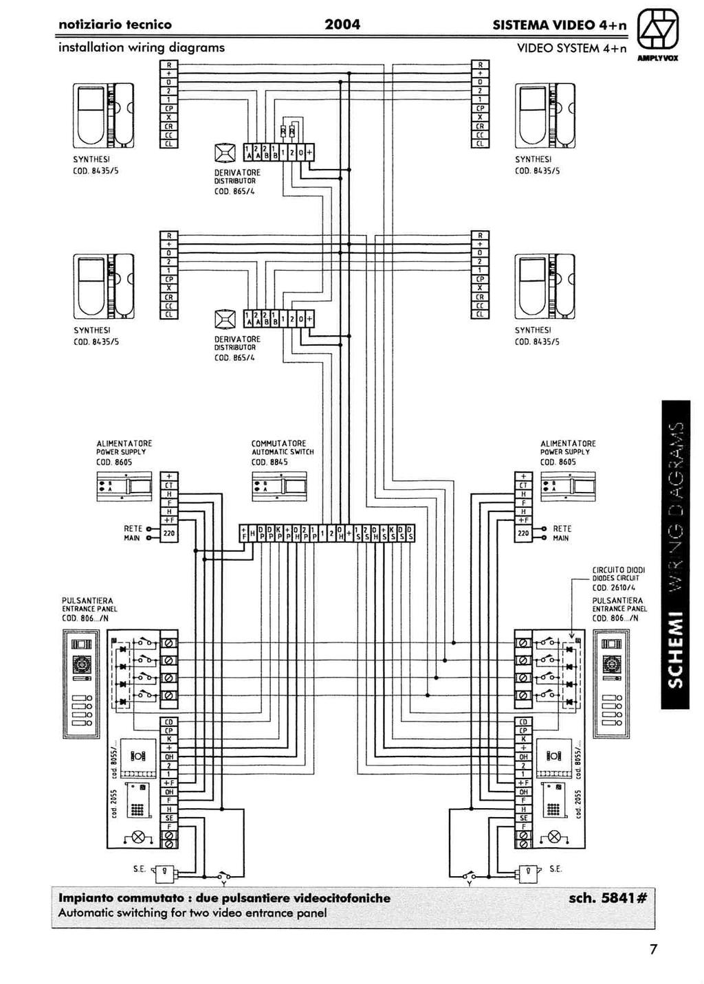
2 notiziario tecnico 2004 SISTEMA VIDEO 4+n installation wiring diagrams VIDEO SYSTEM 4+n INDEX: Description Diagram Page Section of wires 2/UK Suggestions for the correct installation 3/UK Terminal functions monitor Synthesi code 8435/5 4/UK Power supply terminal functions code /UK Audio speaker unit terminal functions code /UK Camera group terminal functions code 8055/ /80 6/UK Interface module for external camera 6/UK Automatic switch terminal functions code /UK Connection diodes circuit code 2610/4 8/UK VIDEO DOOR ENTRY SYSTEM SYNTHESI ( 4+n ) Single residence kit 5801# 1 Single residence kit with external camera 5811#. 2 Dual residence kit 5802# 3 Dual residence kit with external camera 5812# 4 Multi users video door entry system 5820# 5 Automatic switching for two entrance panels : one video and one only audio 5840# 6 Automatic switching for two video entrance panels 5841# 7 Automatic switching for three or more main video entrance panels 5851# 8 Video distributor 9 Monitor in parallel 10 Telephone in parallel 10 Three monitors in parallel without video distributor 11 Monitor with video recall 12 Apartment entrance door call 12 Passive repeater for additional call 13 Long distance connection 13 NOTE a) AMPLYVOX S.p.A suggests to use original components only. b) AMPLYVOX S.p.A. reserves the right to modify the design, construction, composition and equipment as it shall think fit without notifying the buyer and to supply products which may not be in strict accordance with agreed specifications. TO FACILITATE THE READING OF THE DIAGRAM, TERMINAL DATA MAY NOT CORRESPOND TO THE POSITION INDICATED ON THE EQUIPMENT. TO AVOID DAMAGE TO THE PRINTED CIRCUIT, WE SUGGEST THAT TERMINALS ARE NOT OVER TIGHENED. 1/UK
3 notiziario tecnico 2004 SISTEMA VIDEO 4+n installation wiring diagrams VIDEO SYSTEM 4+n LEGEND : Y J S.E. R DOOR OPENER BUTTON APARTMENT CALL ELECTRIC LOCK 12Vac 18VA CHARGE RESISTOR 75 ohm ½ W NAME LABEL FESTOON BULB 24V 3W Section of wires Distance Monitor Power supply + O R X CP 1 2 F H +F OH 50 mt. 1 mm² 0.5 mm² 0.3 mm² 1.5 mm² 100 mt. 1.5 mm² 1 mm² 0.3 mm² 2 mm² 200 mt. 2.5 mm² 1.5 mm² 0.3 mm² twisted 2.5 mm² SUGGESTED INSTALLATION HEIGHTS : Video entrance panel Monitor wall mount bracket (code 806 /n) (code 8435/5) (Mosaico) 2/UK
4 notiziario tecnico 2004 SISTEMA VIDEO 4+n installation wiring diagrams VIDEO SYSTEM 4+n Suggestions for the Correct installation 1) Do not execute any connection, replacement or operation with the system powered. 2) Be carefull installing the external video entrance panel to the right indicated height and avoid installing the camera group in direct view of sunlight. 3) Do not run the cables of the video door system in the same duct of the mains network. 4) There are more than one H terminals on the equipments, it makes no difference which H terminal is used. 5) The CCD video camera is normally supplied with infrared leds built in, to allows a correct vision of the visitor. 6) To supply the name label festoon bulbs in the entrance panel a dedicated trasformer and its wires connection are suggested. Preliminary checks Before main connections: 1) Check that the connections are made following the drawing supplied with the equipment. 2) Check that no short circuit exists between terminals H and +F. 3) Check that no short circuit exists between terminals O and +. 4) The wires 1 and 2 starting from the camera group must present a resistance of about 75 ohms. Note: this measurement is not valid for the single residence video kit. Test of operations 1) Power the system. 2) Push the call button of the external video entrance panel and check if : - the electronic call sounds at the monitor. - the monitors image is clear, stable and defined. - the image needs regulating (operate on brightness and contrast controls). 3) Wait for the automatic turn off of the monitor, then repeat the call to the other apartments. A special circuit in the camera group avoids the simultaneous turn on of more than one monitor. 5) The phonic test must be effected talking at a distance of 30 cms. from the external video entrance panel. The volume of the amplifiers in the external audio unit is normally factory set, however if the amplification proves to be too high or too low, this can be adjusted accordingly via the two potentiometers A and B which can be found at the back of the external audio unit. A = regulates the volume from the inside to the outside B = regulates the volume from the outside to the inside The amplification settings must be carried out with the unit in operation, so as to hear the effects of the settings. It is important to start the adjustments with potentiometer A. However it is important to avoid increasing the volume to a very high level that will produce the feedback whistle due to the larsen effect. 3/UK
5 notiziario tecnico 2004 SISTEMA VIDEO 4+n installation wiring diagrams VIDEO SYSTEM 4+n MONITOR SYNTHESI Code 8435/5. Picture tube: flat 4 screen.. Electronic call: loudspeaker.. Electronic front door apartment call: loudspeaker (different frequency).. 1 push-button: electric lock door release.. 1 push-button: video recall.. 1 push-button: auxiliary services.. Controls: brightness contrast.. Privacy: built-in (can be excluded).. Video connection: with video distributor or in out system. Dimensions : 204 x 220 x 50 mm Housing : technopolymers Jumpers Standard set 75 ohm privacy High privacy 75 ohm no privacy High no privacy IMPORTANT! Use jumpers in the following mode : Use both jumpers (ref. 75 ohm) in systems with video distributors. Remove both jumpers (ref. High) in systems without video distributors ( in out ). IMPORTANT! All monitors must have the Privacy jumper in the same position. TERMINAL FUNCTIONS Code 8435/5 T. Value Function Note 1 Positive video signal Composite video signal 1 Vpp 2 Negative video signal Composite video signal 1 Vpp O 0 V General earth All voltage reference level V = Timed voltage Stand on when timer is working +10 V = closed Phonic input R + 5 V = opened 5 V = Electronic call 0 V Electric lock release control X +18 V = Electronic front door call CP Video recall CL NO contact Auxiliary contact at rest Special function CC Common contact Auxiliary contact common Special function CR NC contact Auxiliary contact at rest Special function 4/UK
6 notiziario tecnico 2004 SISTEMA VIDEO 4+n installation wiring diagrams VIDEO SYSTEM 4+n POWER SUPPLY Code 8605 Dimension : 185 x 100 x 77 mm Housing : ABS ( DIN module ) Protections : Fuse T 200 ma ( primary trasformer ) Fuse F 3.15 A ( secondary trasformer ) TERMINAL FUNCTIONS Code 8605 T. Value Function Note H 0 V General earth All voltage reference level F 16 V ~ Camera group supply Stand on terminal +F +18 V = Camera group supply Stand on terminal CT External timer set Additional supply function V = Timed voltage Additional supply function ST +18 V = Voltage present at rest Special function L NO contact Auxiliary contact at rest Special function R NC contact Auxiliary contact at rest Special function C Common contact Auxiliary common contact Special function S 22 V ~ A.C. voltage-services supply Stand on terminal Vac Input voltage Main AUDIO SPEAKER UNIT Code 2055 Dimensions : Hosing : Regolations : 94 x 57 x 35 mm ABS Potentiometer A (volume from the inside to the outside) Potentiometer B (volume from the outside to the inside) TERMINAL FUNCTIONS Code 2055 T. Value Function Note CP Common push button Yellow ~ 16 V ~ Supply Red Switch set Green H 0 V General earth Black SE Electric lock door release Blue CD Common anode diodes circuits Brown H 0 V General earth Black ~ 16 V ~ Supply Red 5/UK
7 notiziario tecnico 2004 SISTEMA VIDEO 4+n installation wiring diagrams VIDEO SYSTEM 4+n CAMERA GROUP Cod. 8055/80 Cod. 8055/29 Cod. 8055/TX To use with To use with To use with COMPONIBILE entrance panel MOSAICO entrance panel External camera TERMINAL FUNCTIONS T. Value Function Note Code 8055 / 80 Code 8055 / 29 CD CP Common anode diodes circuits Common push button +12 V = at rest K Switch set 0 V call H 0 V General earth All voltage reference level F 16 V ~ Camera group supply Stand on terminal SE 16 V ~ opened 0 V closed Electric lock door release OH 0 V General earth All voltage reference level +F +18 V = Camera group supply Permanent V = Timed voltage 60 sec. 1 Positive video signal Composite video signal 1 Vpp 2 Negative video signal Composite video signal 1 Vpp Ch1 Cathode diode Used only in the video kit Ch2 Cathode diode Used only in the video kit Cod / TX +12 V = at rest K Switch set 0 V call OH 0 V General earth All voltage reference level +F +18 V = Camera group supply Permanent V = Timed voltage 60 sec. 1 Positive video signal Composite video signal 1Vpp. 2 Negative video signal Composite video signal 1Vpp. 75 Ω BNC Coaxial cable core Composite video signal 1Vpp. 6/UK
8 notiziario tecnico 2004 SISTEMA VIDEO 4+n installation wiring diagrams VIDEO SYSTEM 4+n AUTOMATIC SWITCH Cod Dimensions : 185 x 100 x 77 mm housing : ABS (DIN module) Protections : fuse 1 A LEDS : PRI SEC OCC Common contacts close with NC contacts Common contacts close with NO contacts Busy signal works TERMINAL FUNCTIONS Code 8845 T. Value Function Note +F +18 V= Supply Stand on terminal OH 0 V General heart All voltage reference level KP +12 V= at rest 0 V call Reset control KS +12 V= at rest 0 V call Set control RS Busy signal Special function OC Busy signal Special function 1 Positive video signal Common contact 1P Positive video signal NC contact 1S Positive video signal NO contact 2 Negative video signal Common contact 2P Negative video signal NC contact 2S Negative video signal NO contact V= Monitor supply Common contact +P +18 V= Monitor supply NC contact +S +18 V= Monitor supply NO contact DS Common anode diodes circuit Common contact DS Common anode diodes circuit NO contact DP Common anode diodes circuit Common contact DP Common anode diodes circuit NC contact CP Common push buttons Common contact CP Common push buttons NC contact C Auxiliary contact Common contact R Auxiliary contact NC contact L Auxiliary contact NO contact 7/UK
9 notiziario tecnico 2004 SISTEMA VIDEO 4+n installation wiring diagrams VIDEO SYSTEM 4+n INTERNAL CONNECTION (ENTRANCE PANEL) Diodes circuit Code 2610/4 Scoring lines CD (common diodes) 8/UK
10
11
12
13
14
15
16
17
18
19
20
21
22
23
Unlocking of building entrance door shall be possible by pressing the monitor's door-opener button.
 DIGITAL COLOR VIDEO INTERCOM SYSTEM The contractor shall supply, install, test and commission a modern Electronic Digital Color Video Entry Phone System of an approved manufacturer and design to facilitate
Product information. Front-door station series with video for surface-mount
 Product information Front-door station series with video for surface-mount series VPES series VPDS 2 05/2006 Table of contents Scope of delivery...3 Safety notices...3 General notes on the cabling in TCS
The UK sequence is shown below. The duration of each phase can be easily adjusted during the programming to suit.
 The Traffic Light Controller has been designed to replicate the traffic light sequence as used in the UK and on the continent for junction control and road-works. The UK sequence is shown below. The duration
Azatrax Model Railroad Track Signal Control - Single Track
 Installation Guide Azatrax Model Railroad Track Signal Control - Single Track TS2 What it is: The TS2 operates one or two trackside block signals (one in each direction) on one track to simulate the block
HS-509 VIBRATION TRIP MODULE
 HS-509 VIBRATION TRIP MODULE 1. Overview The HS-509 is a configurable trip amplifier capable of accepting a 4-20mA signal from a HS-420 sensor and providing two trip action relay outputs along with an
Art M Digital codelock module
 CODELOCK UNIT MODULES Art. 4900-4900M This module has on the front a 12 stainless steel button keypad (keys from 0 to 9 plus ENTER and CLEAR keys), 2 LEDS for operation signalling, the keypad illumination
AX system. Door stations Control Units & Stations CCTV - Telephony AX system CATA-CHAP7masterUK.indd 93 19/12/ :30
 Door stations... 95 Control Units & Stations... 96 CCTV - Telephony... 100 93 12132-CATA-CHAP7masterUK.indd 93 19/12/2017 12:30 120 1 8 INTERCOM ADVANTAGES: very affordable price flexible installation
POINTS POSITION INDICATOR PPI4
 POINTS POSITION INDICATOR PPI4 Monitors the brief positive operating voltage across points motors when they are switched Lights a corresponding led on a control panel to show the last operation of each
EA63-7D. Generator Automatic Voltage Regulator Operation Manual. Self Excited Automatic Voltage Regulator
 EA63-7D Generator Automatic Voltage Regulator Operation Manual Self Excited Automatic Voltage Regulator SP POWERWORLD LTD Willows, Waterside, Ryhall, Stamford, Lincs, PE9 4EY, UK Tel: +44 1780 756872 -
Enterview 2 / Enterview 2V 4 WIRE VIDEO DOORPHONE SYSTEM
 Enterview / Enterview V WIRE VIDEO DOORPHONE SYSTEM INSTALLATION AND OPERATION. Introduction This Video doorphone System is an easy-to-use system offering many benefits and conveniences, such as relieving
ALM-6813/6812 INSTALLATION AND PROGRAMMING MANUAL
 ALM-6813/6812 INSTALLATION AND PROGRAMMING MANUAL Installation and programming Manual v2.2 1 MARSS Solar Defender SYSTEM This guidebook provides the essential instructions to install and configure the
video door entry system - installation instructions
 4 TRADE 007 AUDIO 008 VIDEO Tel : 0870 00 00 Fax : 0870 00 00 WEB : www.planetsrs.com 8480 oronation Road Park Royal, London NW0 7QJ video door entry system installation instructions IN008v 0008 Getting
TPW300series. CAT5/6 RGBHsVs TRANSCEIVERS
 RGBHsVs Transmitter / Receiver Parallel-settable receivers Jumper type cable loss compensation Suitable for high resolution signals 19" compatible 1 INSTALLATION AND USE OF THE TPW300 SERIES INDEX 1.0
LED Backlight for Technics amplifiers
 LED Backlight for Technics amplifiers Technics SE-A900S Technics SE-A900SM2 Technics SE-A909S Technics SE-A1000 Technics SE-A1000M2 Technics SE-A1010 Rev. 1.2 B Description The LED module is designed to
INSTRUCTION MANUAL MODEL 2710 SUBCARRIER DEMODULATOR
 INSTRUCTION MANUAL MODEL 2710 SUBCARRIER DEMODULATOR Data, drawings, and other material contained herein are proprietary to Cross Technologies, Inc., and may not be reproduced or duplicated in any form
Integre4. Audiophile integrated amplifier. v1.2
 Owner s Manual Integre4 Audiophile integrated amplifier www.lab12.gr v1.2 Table of Contents It is yours Features Unpacking and Warnings Installation & Placement Front Panel Rear Panel Connections Remote
Self Excited Automatic Voltage Regulator For Generator Compatible with Marathon SE350* Operation Manual
 Self Excited Automatic Voltage Regulator For Generator Compatible with Marathon SE350* Operation Manual s * Use for reference purpose only and not a genuine Marathon product. 1. INTRODUCTION Sensing Input
8 PIN PIC PROGRAMMABLE BOARD (DEVELOPMENT BOARD & PROJECT BOARD)
") ESSENTIAL INFORMATION BUILD INSTRUCTIONS CHECKING YOUR PCB & FAULT-FINDING MECHANICAL DETAILS HOW THE KIT WORKS LEARN ABOUT PROGRAMMING WITH THIS 8 PIN PIC PROGRAMMABLE BOARD (DEVELOPMENT BOARD & PROJECT
ESSENTIAL INFORMATION BUILD INSTRUCTIONS CHECKING YOUR PCB & FAULT-FINDING MECHANICAL DETAILS HOW THE KIT WORKS LEARN ABOUT PROGRAMMING WITH THIS 8 PIN PIC PROGRAMMABLE BOARD (DEVELOPMENT BOARD & PROJECT
Installer Manual Video door entry unit with 3.5" monitor for Due Fili (Two-Wire) call system Elvox Vimar Group.
 call system Elvox Vimar Group.") Installer Manual 19558 Video door entry unit with 3.5" monitor for Due Fili (Two-Wire) call system Elvox Vimar Group. Table of Contents Technical characteristics 3 Type of system 3 Advantages of the Due
Installer Manual 19558 Video door entry unit with 3.5" monitor for Due Fili (Two-Wire) call system Elvox Vimar Group. Table of Contents Technical characteristics 3 Type of system 3 Advantages of the Due
SQM40/41 Actuators for air and gas dampers
 SQM40/41 Actuators for air and gas dampers Description SQM40/41 actuators are used for the positioning of flow control valves, butterfly valves, dampers or any application requiring rotary motion. The
Electronic MICROSTAT-T Temperature controller with digital indication for use with resistance thermometers and thermocouples Series 8650
 M. K. JUCHHEIM GmbH & Co Delivery address:mackenrodtstraße 14, 36039 Fulda, Germany Postal address: 36035 Fulda, Germany Phone: +49 661 6003-0 Fax: +49 661 6003-607 E-mail: mail@jumo.net Internet: www.jumo.de
COLOUR CHANGING USB LAMP KIT
 TEACHING RESOURCES SCHEMES OF WORK DEVELOPING A SPECIFICATION COMPONENT FACTSHEETS HOW TO SOLDER GUIDE SEE AMAZING LIGHTING EFFECTS WITH THIS COLOUR CHANGING USB LAMP KIT Version 2.1 Index of Sheets TEACHING
Telemetry Receiver Installation Guide
 BBV Telemetry Receiver Installation Guide Models covered Rx200 Building Block Video Ltd., Unit 1, Avocet Way, Diplocks Industrial Estate, Hailsham, East Sussex, UK. Tel: +44 (0)1323 842727 Fax: +44 (0)1323
OWNER S MANUAL MOTORIZED 7 WIDE TFT LCD COLOR MONITOR CNT-701
 OWNER S MANUAL PW MOTORIZED 7 WIDE TFT LCD COLOR MONITOR CNT-701 ANY CHANGES OR MODIFICATIONS IN CONSTRUCTION OF THIS UNIT DEVICE WHICH IS NOT APPROVED BY THE PARTY RESPONSIBLE FOR COMPLIACE COULD VOID
Flat-Bed Module Recorders
 Flat-Bed Module Recorders Model No. 08376-50 08376-55 08376-60 0115-0192 4/28/00 Table of Contents Introduction...3 Power Requirements...3 Chart Paper Installation...3 Pen Installation...5 Grounding...5
LEVEL CROSSING MODULE FOR LED SIGNALS LCS2
 LEVEL CROSSING MODULE FOR LED SIGNALS LCS2 Fully Flexible Controller for Common-Anode LED signals Automatically detects trains using an infra-red sensor mounted below the track bed Operates attached yellow
WC-2100 WORD CLOCK DISTRIBUTION AMPLIFIER INSTRUCTION MANUAL
 WC-2100 WORD CLOCK DISTRIBUTION AMPLIFIER INSTRUCTION MANUAL SIGMA ELECTRONICS, INC. P.O. Box 448 1027 COMMERCIAL AVE. EAST PETERSBURG, PA 17520-0448 (717) 569-2681 WC-2100 WORK CLOCK DISTRIBUTION AMPLIFIER
I N S T R U C T I O N D A T A
 I N S T R U C T I O N D A T A RFL (C37.94) Fiber Service Unit Single Mode 108015-1 RS-449 108015-2 V.35 108015-3 G.703 108015-4 X.21 108015-5 E1 Multimode 107460-1 RS-449 107460-2 V.35 107460-3 G.703 107460-4
MONO AMPLIFIER KIT ESSENTIAL INFORMATION. Version 2.2 CREATE YOUR OWN SPEAKER DOCK WITH THIS
 ESSENTIAL INFORMATION BUILD INSTRUCTIONS CHECKING YOUR PCB & FAULT-FINDING MECHANICAL DETAILS HOW THE KIT WORKS CREATE YOUR OWN SPEAKER DOCK WITH THIS MONO AMPLIFIER KIT Version 2.2 Build Instructions
ex 800 Series ematrix System
 Protecting Your Human Assets During Emergency ex 800 Series ematrix System The ex 800 Series ematrix System is a fully integrated and versatile public address system which is designed distinctively to
EA350. Generator Automatic Voltage Regulator Operation Manual
 Generator Automatic Voltage Regulator Operation Manual Self Excited Automatic Voltage Regulator For General Generators Compatible with Marathon SE350* * Use for reference purpose only and not a genuine
Multi-Key v2.4 Multi-Function Amplifier Keying Interface
 Multi-Key v2.4 Multi-Function Amplifier Keying Interface ASSEMBLY & OPERATION INSTRUCTIONS INTRODUCTION The Harbach Electronics, LLC Multi-Key is a multi-function external device designed for the safe
New product of near infrared (to 900 nm) detection
 detection") WITH THERMOELECTRIC COOLER H7844 New product of near infrared (to 900 nm) detection FEATURES A newly developed high sensitivity multialkali side-on photomultiplier tube Fast cooling (3 minutes) by thermoelectric
WITH THERMOELECTRIC COOLER H7844 New product of near infrared (to 900 nm) detection FEATURES A newly developed high sensitivity multialkali side-on photomultiplier tube Fast cooling (3 minutes) by thermoelectric
AMU2-2MHD+ Audio monitoring Unit
 AMU2-2MHD+ Audio monitoring Unit Handbook TSL Vanwall Road, Maidenhead, Berkshire, SL6 4UB Telephone +44 (0)1628 676200, FAX +44 (0)1628 676299 AMU2-2MHD+-6 1 ISSUE 5 SAFETY Installation. Unless otherwise
SMART SYSTEM DUOX SYSTEM GUIDE
 SMART SYSTEM DUOX SYSTEM GUIDE This document shows the basic concepts for a quick start-up. For more information download the manuals at www.fermax.com Technical publication of an informative nature published
BBV REAL TIME HQ DISPLAY QUAD MANUAL
 BBV REAL TIME HQ DISPLAY QUAD MANUAL Building Block Video Ltd., 17 Apex Park, Diplocks Industrial Estate, Hailsham, East Sussex, BN27 3JU, UK. Tel:+44 (0)1323 842727 Fax:+44 (0)1323 842728 Support:+44(0)1323
DUAL/QUAD DISPLAY CONTROLLER Operation Manual
 DUAL/QUAD DISPLAY CONTROLLER Operation Manual Model PXD524 MicroImage Video Systems division of World Video Sales Co., Inc PO Box 331 Boyertown, PA 19512 Phone 610-754-6800 Fax 610-754-9766 sales@mivs.com
Video Streamer Modifications
 CB Electronics Video Streamer Modifications CB Electronics Loddonside, Lands End House, Beggars Hill Road, Charvil, Berks RG10 0UD, UK Tel: +44 (0)118 9320345, Fax: +44 (0)118 9320346 URL: www.colinbroad.com
Model FS-4608R. Features. Overview
 Model FS-4608R Features 8-Channel Active Video Receiver Hub(dual video output) Full-motion color video signal up to 3936ft(1200m) via UTP cat5e/6 NTSC, PAL & SECAM video format compatible Real-time transmission
MULTIDYNE INNOVATIONS IN TELEVISION TESTING & DISTRIBUTION DIGITAL VIDEO, AUDIO & DATA FIBER OPTIC MULTIPLEXER TRANSPORT SYSTEM
 MULTIDYNE INNOVATIONS IN TELEVISION TESTING & DISTRIBUTION INSTRUCTION MANUAL DVM-1000 DIGITAL VIDEO, AUDIO & DATA FIBER OPTIC MULTIPLEXER TRANSPORT SYSTEM MULTIDYNE Electronics, Inc. Innovations in Television
Video & Audio Transmission
 CCTV Video, Audio Distribution Amplifier, Video & Power over one Coax AA001 In Line Audio Pickup Box Audio pick up works individually without any other equipment. One add-on mini audio box for all cameras
ACT 10 Digital Keypad Operating & Installation Instructions This manual is found at
 ACT 10 Digital Keypad Operating & Installation Instructions 18-00001 This manual is found at www.eaglesecuritysolutions.co.uk Installation Notes Always remember to factory default the controller before
3G fiber. TL7070 3G/HD-SDI + DVI(HDMI) Fiber plus Coax Output Video Transmitter. TL Features. Block Diagram TL7070
 Fiber plus Coax Output Video Transmitter. TL Features. Block Diagram TL7070") Thunder Link is a family of small form factor modules for formatting and converting generic digital video streams to standard compliant formats. Different interface standards are supported from the transmitter
Thunder Link is a family of small form factor modules for formatting and converting generic digital video streams to standard compliant formats. Different interface standards are supported from the transmitter
Vorne Industries. 87/719 Analog Input Module User's Manual Industrial Drive Itasca, IL (630) Telefax (630)
 Telefax (630)") Vorne Industries 87/719 Analog Input Module User's Manual 1445 Industrial Drive Itasca, IL 60143-1849 (630) 875-3600 Telefax (630) 875-3609 . 3 Chapter 1 Introduction... 1.1 Accessing Wiring Connections
Vorne Industries 87/719 Analog Input Module User's Manual 1445 Industrial Drive Itasca, IL 60143-1849 (630) 875-3600 Telefax (630) 875-3609 . 3 Chapter 1 Introduction... 1.1 Accessing Wiring Connections
FORESIGHT CCTV INC. TWISTED PAIR TRANSMISSION SYSTEM Passive Series
 TWISTED PAIR TRANSMISSION SYSTEM Passive Series ITEM NO.: TTP111V, TTP111VT, TTP111VF, TTP111VH, TTP111VCT, TTP111VP, TTP111AV, TTP414V, TTP414VH, TTP414VD, TTP444V, TDP414V, TDP414VP Features: Transmit
Operating instructions Electronic preset counter Type series 717
 Operating instructions Electronic preset counter Type series 717 1. Description 5.98.3_gb 6-digit adding/subtracting counter with two presets Very bright 8mm high LED display Counting and preset range
Warner Photoscanner MCS-500 Series LED Photoelectric Control
 Warner Photoscanner MCS-500 Series LED Photoelectric Control P-241-100 819-0504 Installation & Operating Instructions Contents Description.............................. 2 Specifications.........................
ABB i-bus EIB Universal dimmer 6155 EB for Installation
 73-1 - 5975 23459 ABB i-bus EIB Universal dimmer 6155 EB - 101-500 for Installation Operating instructions only for authorized, skilled electricians with EIB training Important instructions Attention It
Nutube.US. 6P1 Evaluation Board. User Manual
 Nutube.US 6P1 Evaluation Board User Manual Introduction The 6P1 Evaluation Board (EVB) is a vehicle for testing and evaluating the Korg Nutube 6P1 dual triode in audio circuits. This product is designed
Synchro System PHOTO NOT AVAILABLE. Description. Applications. Features
 Innovative Solutions in Engineering BBG-RSSS-90-400-1 Redundant Serial to Synchro System Description PHOTO NOT AVAILABLE Applications Radar Systems (antenna azimuth) Navigation Systems (gyrocompass, speedlog,
TIL311 HEXADECIMAL DISPLAY WITH LOGIC
 TIL311 Internal TTL MSI IC with Latch, Decoder, and Driver 0.300-Inch (7,62-mm) Character Height Wide Viewing Angle High Brightness Left-and-Right-Hand Decimals Constant-Current Drive for Hexadecimal Characters
Camera Setup Instructions
 Camera Setup Instructions Hopefully this document will help new MallinCam owners set up their systems and get them to successful first light more quickly. Through the use of images, I hope to describe
One channel video link With duplex data and contact closure
 User Manual One channel video link With duplex data and contact closure CFO First Mile series consist of fi bre optic modems which provide a high quality and losless video transmission for variety of CCTV
K-Steel. The strength of security.
 HOME OFFICE K-Steel. The strength of security. The K-Steel entrance panel, designed and tested to cater to all needs, is eye-catching, modular and armored. A simple glance immediately confirms all the
150(5-7/8") 272.5(10-3/4") IN USE ABC DEF GHI JKL MNO PQRS TUV WXYZ. Unit center. 100(3-15/16") (Bracket-mounting pitch) 110(4-5/16") (GF-3B size)
 272.5(10-3/4) IN USE ABC DEF GHI JKL MNO PQRS TUV WXYZ. Unit center. 100(3-15/16) (Bracket-mounting pitch) 110(4-5/16) (GF-3B size)") NI8 June, 2017UDATEREVI PRODUCT ESDRAWINGDGF3B) FL=1300(4'3") or 1500 TIOENTRANCE ODELNO.MOUNTING(using NGTDMBNMSTATION CRIP Unit FL=1187.5(463/4") or 1387.5(545/8") IGFIGG5561816F.NAMEPRODUCT DRAWING.NO.Unit
NI8 June, 2017UDATEREVI PRODUCT ESDRAWINGDGF3B) FL=1300(4'3") or 1500 TIOENTRANCE ODELNO.MOUNTING(using NGTDMBNMSTATION CRIP Unit FL=1187.5(463/4") or 1387.5(545/8") IGFIGG5561816F.NAMEPRODUCT DRAWING.NO.Unit
Model /29S RF Splitter
 Instruction Manual Model 1584-29/29S RF Splitter March 2013, Rev. 0 LNB VOLTAGE A B MODEL 1584 COMBINER CROSS TECHNOLOGIES INC. GND+DC ON Data, drawings, and other material contained herein are proprietary
multi-function meters
 multi-function meters eclipse 2 eclipse 7 installation and operating manual 1 GENERAL DESCRIPTION 2 INSTALLATION 3 WIRING INFORMATION 4 2 ECLIPSE 2 METERS 2.1 PROGRAMMING THE METER 5 2.2 INFORMATION 6
OPERATING MANUAL. DMX / DSI / DALI Dekoder 3004B-H Mk2
 OPERATING MANUAL DMX / DSI / DALI Dekoder 3004B-H Mk2 (C) SOUNDLIGHT 1996-2004 * ALL RIGHTS RESERVED * NO PART OF THIS MANUAL MAY BE REPRODUCED, DUPLICATED OR USED COMMERCIALLY WITHOUT THE PRIOR WRITTEN
QUIZ BUZZER KIT TEACHING RESOURCES. Version 2.0 WHO ANSWERED FIRST? FIND OUT WITH THIS
 TEACHING RESOURCES SCHEMES OF WORK DEVELOPING A SPECIFICATION COMPONENT FACTSHEETS HOW TO SOLDER GUIDE WHO ANSWERED FIRST? FIND OUT WITH THIS QUIZ BUZZER KIT Version 2.0 Index of Sheets TEACHING RESOURCES
MULTIS L72. Operating instructions
 GB MULTIS L72 Operating instructions 2 SOCOMEC - Ref. : 876 091B ENGLISH GB Contents PRELIMINARY OPERATIONS 4 GENERAL INFORMATION 5 PRESENTATION 4 INSTALLATION 5 Mechanical environment Climatic environment
Quad Video Switching Box User Manual
 Quad Video Switching Box User Manual The Solution for Vehicle safety Table of Contents PRECAUTIONS 3 IDENTIFYING THE PARTS 4 INSTALLATION DIAGRAM...5 Camera or video input/output.. 5 Camera or video display...6
STX Stairs lighting controller.
 Stairs lighting controller STX-1795 The STX-1795 controller serves for a dynamic control of the lighting of stairs. The lighting is switched on for consecutive steps, upwards or downwards, depending on
Industriefunkuhren. Technical Manual. IRIG-B Generator-Module for analogue / digital Signals of Type: IRIG-B / IEEE C / AFNOR NF S87-500
 Industriefunkuhren Technical Manual IRIG-B Generator-Module for analogue / digital Signals of Type: IRIG-B / IEEE C37.118 / AFNOR NF S87-500 Module 7628 ENGLISH Version: 02.01-06.03.2013 2 / 20 7628 IRIG-B
Operation Manual TX20 1/8 DIN Microcomputer Based ph/orp Controller with relays
 Operation Manual TX20 1/8 DIN Microcomputer Based /ORP Controller with relays 11751 Markon Drive Garden Grove, CA. 92841 U.S.A. pg. 1 CONTENTS GENERAL INTRODUCTION.....3 INITIAL INSPECTION......3 USING
Telemetry Receiver Installation Guide
 BBV Telemetry Receiver Installation Guide Models covered Rx400P Building Block Video Ltd., Unit 1, Avocet Way, Diplocks Industrial Estate, Hailsham, East Sussex, UK. Tel: +44 (0)1323 842727 Fax: +44 (0)1323
TL7050 Dual 3G/HD-SDI + DVI(HDMI) Output Video Transceiver. TL Features. Block Diagram TL7050
 Output Video Transceiver. TL Features. Block Diagram TL7050") 3G ishot XBlock is a family of small form factor modules for formatting & converting gene ric digital video streams to standard compliant formats. Different interface standards are supported from the transmitter
3G ishot XBlock is a family of small form factor modules for formatting & converting gene ric digital video streams to standard compliant formats. Different interface standards are supported from the transmitter
CURRENT INJECTION RELAY TESTER CR-100. ( Code P60212 (770081) ) INSTRUCTIONS MANUAL ( M / 05A ) (c) CIRCUTOR S.A.
 ) INSTRUCTIONS MANUAL ( M / 05A ) (c) CIRCUTOR S.A.") CURRENT INJECTION RELAY TESTER CR-100 ( Code P60212 (770081) ) INSTRUCTIONS MANUAL ( M 981 329 / 05A ) (c) CIRCUTOR S.A. ---- CURRENT- TIME TRIP TESTER CR-100 --------------- Page. 2 CURRENT INJECTION
CURRENT INJECTION RELAY TESTER CR-100 ( Code P60212 (770081) ) INSTRUCTIONS MANUAL ( M 981 329 / 05A ) (c) CIRCUTOR S.A. ---- CURRENT- TIME TRIP TESTER CR-100 --------------- Page. 2 CURRENT INJECTION
Ophera Hands Free Color Video Receiver and Accessories
 Sold by: http://www.twacomm.com Toll Free: (877) 389-0000 Ophera Hands Free Color Video Receiver and Accessories APPLICATION The Ophera Video Entry system integrates high quality color video and audio
Build A Video Switcher
 Build A Video Switcher VIDEOSISTEMAS serviciotecnico@videosistemas.com www.videosistemas.com Reprinted with permission from Electronics Now Magazine September 1997 issue Copyright Gernsback Publications,
SPECIAL SPECIFICATION 6735 Video Optical Transceiver
 2004 Specifications CSJ 0924-06-244 SPECIAL SPECIFICATION 6735 Video Optical Transceiver 1. Description. This Item governs the furnishing and installation of Video optical transceiver (VOTR) in field location(s)
MULTIDYNE Electronics, Inc. Innovations in Television Testing & distribution
 INSTRUCTION MANUAL DVM-2200 DIGITAL VIDEO, AUDIO & DATA FIBER OPTIC MULTIPLEXER TRANSPORT SYSTEM MULTIDYNE Electronics, Inc. Innovations in Television Testing & distribution 1-(800)-4TV-TEST, 1-(800)-488-8378
CR-R880-BL: Indoor/Outdoor Proximity Reader with 10cm (4in) read range
 read range") CR-R880-BL: Indoor/Outdoor Proximity Reader with 10cm (4in) read range Installation Manual Table of Contents Basic Operation...2 CR-R880-BL Block Diagram...2 Technical Specifications...3 Features...4
CR-R880-BL: Indoor/Outdoor Proximity Reader with 10cm (4in) read range Installation Manual Table of Contents Basic Operation...2 CR-R880-BL Block Diagram...2 Technical Specifications...3 Features...4
FTS84/85 Feature Application Field. Temperature & Humidity / Flow Measuring Specialist. Monitor gas and flow for industrial process
 FTS84/8 Feature Application Field Capable of temperature compensation and linear adjustment Double line character : air velocity & temperature Switch for physical quantity:[m/s] [ft/s] [km/h] [mph] [knot]
AK-PVE4 Operating Instructions. Measuring of norm signals in wall-type units. Performance:
 AK-PVE4 Operating Instructions Measuring of norm signals in wall-type units 1 2 P Performance: Digit heights: 20 mm Colour: red Display range: -999 9999 Wall-type housing: light grey made of ABS-plastic
30 mm Push Buttons 9001 K and SK Selector Switches
 30 mm Push Buttons 9001 K and SK Selector Switches NOTE: To order, add prefix 9001 to the beginning of the catalog number. Table 19.184: 4-Position Selector Switches Contact Block Position Side 2 Side
Wind Indicator LED. Contents. Instruction for Use xx.x00, x08, xx.10
 Wind Indicator LED Instruction for Use 4.3225.xx.x00, 4.3225.10.x08, 4.3225.xx.10 Contents 1. General Information 2 1.1 Versions of the Indicator 2 1.2 Elements of the Indicator 3 2. Installation 4 2.1
RAKK dac. RAKK dac Mark IV. RAKK dac Mark IV. Assembly and Installation Manual
 RAKK dac RAKK dac Mark IV RAKK dac Mark IV Assembly and Installation Manual Version 1.3 2013-2014 Raleigh Audio version Use this manual with RAKK dac Mark IV v 2.0, which is marked on the board. Required
PART 1: HARDWARE. Author: Vandermeerschen M. Version
 PART 1: HARDWARE Author: Vandermeerschen M. 1 Version 1.07 L 230VAC N 2 LUXOM SEGMENT Power supply 24VDC BUS termination Push Button Feedback without extra wiring I/O Interface BUS RS232 Relay module 230VAC
instruction manual Model 619YY video dual vertical line generator s/n
 instruction manual Model 619YY video dual vertical line generator s/n september 2005 WARNING This equipment generates, uses and can radiate radio frequency energy and if not installed and used in accordance
AC182A 8 Input x 8 Output S-Video Matrix Switch with Audio
 Heading AC180A 8 Input x 8 Output Composite Video Matrix Switch with Audio MARCH 2005 AC180A AC182A AC182A 8 Input x 8 Output S-Video Matrix Switch with Audio CUSTOMER SUPPORT INFORMATION Order toll-free
USER INSTRUCTIONS MODEL CSI-200 COAXIAL SYSTEM INTERFACE
 USER INSTRUCTIONS MODEL CSI-200 COAXIAL SYSTEM INTERFACE 9350-7676-000 Rev B, 5/2001 PROPRIETARY NOTICE The RTS product information and design disclosed herein were originated by and are the property of
T850 Day & Night Security Camera
 T850 Day & Night Security Camera For use with Swann 4500 DVR EN INSTRUCTION MANUAL MT850_091014E Swann 2014 Before you begin Introduction Congratulations on your purchase of this T850 Day & Night Security
S op o e p C on o t n rol o s L arni n n i g n g O bj b e j ctiv i e v s
 ET 150 Scope Controls Learning Objectives In this lesson you will: learn the location and function of oscilloscope controls. see block diagrams of analog and digital oscilloscopes. see how different input
TL7050 Dual 3G/HD-SDI + DVI(HDMI) Output Video Transceiver. TL Features. Block Diagram TL7050. Dual 3G-SDI + DVI(HDMI) Output
 Output Video Transceiver. TL Features. Block Diagram TL7050. Dual 3G-SDI + DVI(HDMI) Output") Thunder Link is a family of small form factor modules for formatting and converting generic digital video streams to standard compliant formats. Different interface standards are supported from the transmitter
Thunder Link is a family of small form factor modules for formatting and converting generic digital video streams to standard compliant formats. Different interface standards are supported from the transmitter
1995 METRIC CSJ SPECIAL SPECIFICATION ITEM 6573 CCTV CENTRAL EQUIPMENT
 1995 METRIC CSJ 0196-03-209 SPECIAL SPECIFICATION ITEM 6573 CCTV CENTRAL EQUIPMENT 1.0 DESCRIPTION. THIS ITEM SHALL GOVERN FOR THE FURNISHING AND INSTALLATION OF CLOSED CIRCUIT TELEVISION (CCTV) CENTRAL
Model 1476-C SuperQuad HR
 Model 1476-C SuperQuad HR Installation and Operating Instructions Table of Contents Page Table of Content... 2 System Description... 3 Features... 3 Installation... 4 Internal Setups... 4 Connections...
263 Series LED Bargraph Indicator and Controllers
 263 Series LED Bargraph Process Control Water Treatment High resolution 51 segment LED Bargraph for easy reading Accuracy 1% Red display Vertical or Horizontal mounting & stackable Connection Diagrams
Doorphone Video Intercom
 HOME SERIES INSTRUCTION MANUAL Doorphone Video Intercom with Colour 4.3 LCD Monitor EN Getting to know your LCD Screen (Front) 1 2 3 4 5 6 1) LCD Screen - This is where you view your visitor that the intercom
MAXCOM PRODUCT SPECIFICATIONS FIBER OPTIC VIDEO / AUDIO / ASI LINK. Model MX3257HD. Description. Features. Model Selection Guide
 MAXCOM PRODUCT SPECIFICATIONS FIBER OPTIC VIDEO / AUDIO / ASI LINK Model MX3257HD Description The rack-mountable MX3257HD fiber optic video multiplexer is ideal for transmitting 1 channel of video, 2 channels
CONSONANCE PREAMPLIFIER OWNER S MANUAL
 CONSONANCE PREAMPLIFIER OWNER S MANUAL TABLE OF CONTENTS Introduction Initial Inspection Features Installation Input Impedance Adjustments Preamplifier Internal View Impedance Adjustment Diagram Overall
Pixie Construction Notes
 Pixie Construction Notes PCB V2a February 4 th 2015 Please note that this document is still currently under revision and we apologise for any errors or omissions. Readers should feel free to e-mail any
Standard signal metering in wall-mounting case
 User manual AKV-2VR4C Standard signal metering in wall-mounting case Technical features: Digit height: 20 mm Colour: red Range of display: -999 9999 Wall-mounting case: black, made of ABS-plastic Protection
Model 6010 Four Channel 20-Bit Audio ADC Data Pack
 Model 6010 Four Channel 20-Bit Audio ADC Data Pack Revision 3.1 SW v1.0.0 This data pack provides detailed installation, configuration and operation information for the Model 6010 Four Channel 20-bit Audio
TECHNOLOGY USER MANUAL TEKNA PLUS SE MONITOR. Code TTEKNA PLUS SE EN REV.0216
 TECHNOLOGY USER MANUAL TEKNA PLUS SE MONITOR Code 50123594 TTEKNA PLUS SE EN REV.0216 2 INTROUCTION First of all, we thank and congratulate you for purchasing this product manufactured by Golmar. Our commitment
IRT Eurocard. Type RWA RF Distribution Amplifier for 70 MHz IF signals
 I R T Electronics Pty Ltd A.B.N. 5 000 8 575 6 Hotham Parade, ARTARMON N.S.W. 064 AUSTRALIA National: Phone: (0) 949 744 Fax: (0) 949 749 International: +6 949 744 +6 949 749 Email: sales@irtelectronics.com
Frequently Asked Questions
 Frequently Asked Questions Wire and Installation What kind of wire to use with FORESIGHT Twisted Pair Transmission products? Use UTP (unshielded twisted pair) CAT 5 24 AWG (or over) to have the best transmission
INSTALLATION MANUAL FT-FOTR-1VDE-ST-S
 INSTALLATION MANUAL FT-FOTR-1VDE-ST-S 1-Channel Digital Duplex Baseband Video Transmitter and Receiver With Reverse Data Transmission & Ethernet Transmission v1.0 4/5/11 1 PACKAGE CONTENTS This package
Practical Exercise Look at the circuit diagram shown. What will happen in this circuit if switch S2 is pressed momentarily?
 Practical Exercise 3 1. Two electronics technicians are discussing the resistance of copper wire. Technician A says that the resistance of copper wire increases as its cross-sectional area increases. Technician
Installation and operation manual. Art. 69AM/T Switching module for ELVOX DUE FILI (2-wire systems)
") Installation and operation manual Art. 69A/T Switching module for ELVOX DUE FILI (2-wire systems) CONTTS PAGE - WARNINGS FOR THE INSTALLER 2 1. GERAL INFORATION 3 2. ELECTRICAL INSTALLATION 4 3. HARDWARE
Installation and operation manual Art. 69A/T Switching module for ELVOX DUE FILI (2-wire systems) CONTTS PAGE - WARNINGS FOR THE INSTALLER 2 1. GERAL INFORATION 3 2. ELECTRICAL INSTALLATION 4 3. HARDWARE
R1MS-GH3 BEFORE USE... POINTS OF CAUTION INSTRUCTION MANUAL THERMOCOUPLE & DC INPUT MODULE MODEL. (8 points; isolated)
") INSTRUCTION MANUAL THERMOCOUPLE & INPUT MODULE (8 points; isolated) MODEL BEFORE USE... Thank you for choosing M-System. Before use, please check contents of the package you received as outlined below.
INSTRUCTION MANUAL THERMOCOUPLE & INPUT MODULE (8 points; isolated) MODEL BEFORE USE... Thank you for choosing M-System. Before use, please check contents of the package you received as outlined below.