|
|
|
- Rhoda Brianna Leonard
- 5 years ago
- Views:
Transcription
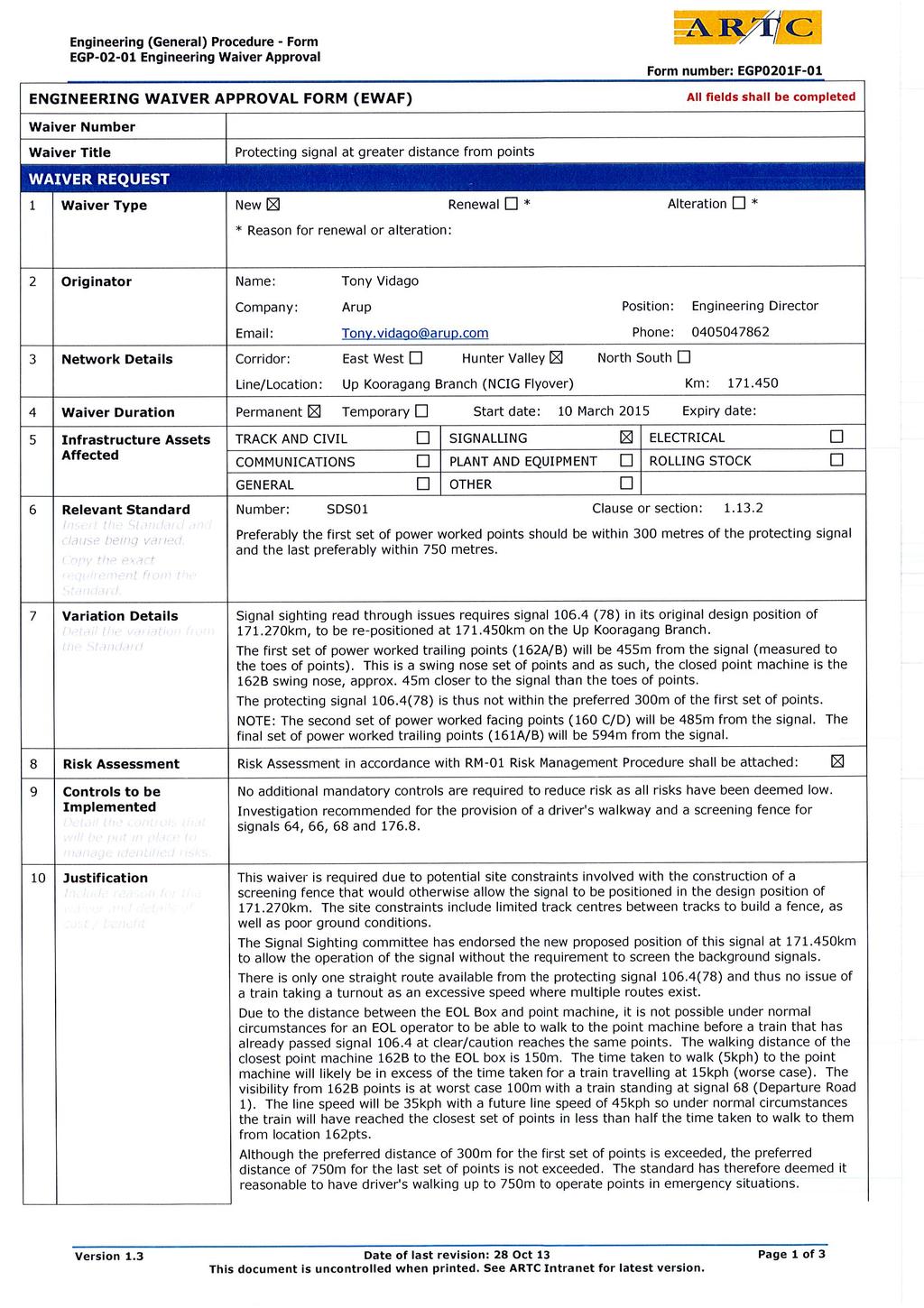
1 HV/SG/0027 N/A


2
3 HV/SG/0027
4
5
6 Technical Note Level Kent Street PO Box 76 Millers Point Sydney 2000 Australia t f d Project title cc Newcastle Coal Infrastructure Group, Coal Export Terminal Stage 2F Job number File reference /TN/008 Prepared by Raymond Lowe Date 2 March 2015 Subject i Signal Sighting Committee Minutes and Report Signal B106.4 (78) 12th February Introduction 1.1 Document Purpose This document has been produced as a record of discussions and the decisions made by the signal sighting committee on the 12 th February 2015 regarding the position of B106.4 (78) signal on the Up Kooragang Branch. 1.2 Sighting Committee Attendance Refer to the ARTC Signal Sighting Attendance List Form, dated 12 th February 2015, and the signed Signal Sighting Form C361SSF023 Rev Pre-Walkout Brief During the previous signal sighting for B106.4 (78) signal, conducted on 29 th January 2015, read-through issues were identified with NCIG departure road Signals 64, 66, 68 (future) and (future) in the background of Signal B106.4 (78). The signal sighting committee concluded that a fence would be required to be built to obscure Signals 64, 66, 68 (future) and (future). At the time of the second sighting committee for B106.4 (78) held 12 th February 2015, the preliminary design of the fence revealed that not all signals can be obscured due to insufficient track centres between Departure Road 1 and the UP Kooragang Branch. The maximum constructible extent of the fence, based on a minimum 3.0m clearance to the nearest running rail #1, will not obscure signal 68 when signal B106.4 (78) (in its original design position of km) is first visible when the train driver is under the fly-over bridge structure. #1 In accordance with the ARTC Heavy Haul Infrastructure Guidelines and ETM-07-01, the minimum clearance from track centre for the fence structure is 4.3m, which exacerbates the constructability constraints identified in the preliminary design using 3.0m clearance to the face of the nearest running rail. Refer to Section 3.4 Post Meeting Note. Due to the constructability risks with the fence, as well as the fact that the preliminary fence design resulted in Signal 68 being visible during the initial sighting of B106.4 (78), the project decided to investigate the option to relocate Signal B106.4 (78) back approximately 140m closer to the flyover to reduce the read H:\PROJECTS\NCIG 2F DD\SSF\SIGNAL 78 SIGHTING\ TN-008 SIGNAL SIGHTING REPORT - SIGNAL B106 4 (78) - 12 FEB 2015.DOCX Arup F0.15 Page 1 of 8
7 Technical Note March 2015 through problem without the installation of a fence. The initial suggestion was to move it such that the signal is positioned 125m from the entry to the flyover to provide adequate sighting. The main issues with the repositioning of signal B106.4 (78) towards fly-over (away from points) were highlighted as follows: The existing design position of Signal B106.4 (78) is 300m from 160 points which is at the limit of the preferred maximum distance that signals associated with points should be from the points. Moving the signal further away will not be in accordance with SDS-01 Principle Whilst the immediate read-through problem will be eliminated, the NCIG departure road signals will still become visible when the train is under the fly-over bridge structure, and will be passed by drivers as they travel along the UP Kooragang Branch. 2.0 Walkout and Sighting 10am 12th February 2015 Note: The original design position for Signal B106.4 (78) was km. The required (optimal) sighting distance for 45kph is 125m. 2.1 Signal B106.4 (78) at km (140m from original position) At this position the signal is visible from the entry to the flyover, 125m away. However, due to the curvature of the track on approach to the fly-over from KCT, whilst the signal will become visible much further back (approx. 300m), it then becomes obscured again by the fly-over abutment, before returning to sight. This was deemed unacceptable by the train operator representatives. Moving the signal closer to the original design position at km (away from flyover) only worsened the situation. 2.2 Signal B106.4 (78) at (180m from original position) At this position there were no sighting issues and the signal was visible from approx. 200m away from the flyover bridge (the worst case position) such that the signal will be continuously visible and not obstructed by the fly-over abutment. It was observed that the NCIG Departure Signals 64 and 66 are visible part-way through the flyover underpass. It was agreed on site that positioning Signal B106.4 (78) at km was acceptable, taking into consideration that the NCIG Departure road signals become visible when the train is under the flyover bridge. The driver s advised that with the signal in this position, drivers could potentially stop in advance of the flyover. SPAD mitigation measures for some of the train operators require trains to stop 50m before the signal, and to slowly crawl up to the signal. H:\PROJECTS\NCIG 2F DD\SSF\SIGNAL 78 SIGHTING\ TN-008 SIGNAL SIGHTING REPORT - SIGNAL B106 4 (78) - 12 FEB 2015.DOCX Arup F0.15 Page 2 of 8 Technical Note
 viewed from worst-case position on the curve approaching flyover. 64 66 68 (future) B106.4(78) (171.450km) B106.")
 with original design position (171.")
8 Technical Note March 2015 Figure 1 Signal B106.4 (78) (at km) viewed from worst-case position on the curve approaching flyover (future) B106.4(78) ( km) B106.4(78) ( km) (future) Figure 2 - View from 15m in front of signal B106.4 (78) (at km) with original design position ( km) also indicated H:\PROJECTS\NCIG 2F DD\SSF\SIGNAL 78 SIGHTING\ TN-008 SIGNAL SIGHTING REPORT - SIGNAL B106 4 (78) - 12 FEB 2015.DOCX Arup F0.15 Page 3 of 8 Technical Note
9 Technical Note March Post Walkout Discussions 3.1 B106.4 (78) Signal at Original Design Position ( km) with Fence A fence obscuring all signals was deemed (at the previous sighting committee meeting on 29th January 2015) to be an acceptable solution if B106.4 (78) is to remain in its designed position at km. However, the preliminary fence design shows that Signal 68 will still be visible when B106.4 (78) is first sighted from under the fly-over bridge. It was agreed that this could still lead to driver confusion, so as it stands the fence is not an acceptable solution. The fence design is being further developed by Aurecon Hatch. Once complete, the final understanding of the visibility of other signals will be advised to the sighting committee members. 3.2 Reposition B106.4 (78) Signal to km The following issues were discussed in relation to positioning Signal B106.4 (78) at km without fencing: Issue Comments Resolution Sighting Distance Sighting distance is greater than 200m (requirement was 125m for 45kph) Accepted OK Continuous sighting on approach At km there is uninterrupted sighting. Due to the curvature of the track the signal would be obstructed on approach if it is Accepted OK NCIG Departure Signals visible on approach (when train driver is under the flyover) and when train stopped at 78. Train travelling on UP Kooragang having passed signal 78 at clear or caution, but then seeing Red aspects from NCIG departure signals to the left. This could lead to driver confusion and/or conditioning to passing near signals at danger. Adequate Standage for train at Signal 78 to be clear of 101 points. Distance of Signal from Points positioned any closer to 162PTS. Other signals aspects can be seen in the distance but driver route knowledge and brightness of immediate signal 78 will be adequate to mitigate against driver acting on the wrong signal. One driver commented that in an ideal world a fence to obscure the NCIG departure signals would be constructed in addition to relocating the signal, however, the absence of a fence was accepted. The next relevant signal on the Up Kooragang Branch is Signal 82 (shunt) and Signal 84 (main), which are beyond the junction with NCIG departure roads on the other side of the Hunter River bridge. Driver Route Knowledge will mitigate risk of confusion as no other signals are expected for this line once Signal 78 has been passed. The distance from proposed km to 101 points ( km) is in excess of 2000m. Even with a train stopped before the flyover bridge (100m before the signal) there will still be adequate standage to clear 101 points. Proposed Signal position is approx. 480m from 162 points, well beyond the preferred maximum distance of 300m. A waiver will likely be required. Figure 3 - Issues and Resolutions - Positioning Signal B106.4 (78) at km Accepted OK Accepted OK Accepted OK Follow up required. H:\PROJECTS\NCIG 2F DD\SSF\SIGNAL 78 SIGHTING\ TN-008 SIGNAL SIGHTING REPORT - SIGNAL B106 4 (78) - 12 FEB 2015.DOCX Arup F0.15 Page 4 of 8 Technical Note
10 Technical Note March Conclusion The original design position of Signal B106.4 (78) at km with a fence only partially eliminating read through to the NCIG departure road signals is not acceptable. Alternative fence designs are being investigated. The repositioning of Signal 78 to km, without a fence to obscure signals, is an acceptable option and was agreed by the signal sighting committee subject to this Report being circulated for review and subsequently being attached to the signal sighting form. 4.0 Post Meeting Notes 4.1 Fence Structure Clearance In accordance with ARTC Heavy Haul Guidelines and ETM the minimum clearance from the adjacent track centre is 4.3m. The fence investigations will be based on this requirement moving forward, rather than 3.0m to the face of the nearest running rail as used previously. 4.2 LED Signal Details Existing Signals The existing signals are Westinghouse RM4 Standard Range Mainline type with Sighting Distance >= 0.5km in accordance with ARTC Type approval Signal Description and Type NG64 (Westinghouse Standard range - as per ARTC Type approval ) Green RM4 MS:GCFB-25B-AU 10V Yellow RM4 MS:YCFB-43B-AU 10V Red RM4 MS:RCFB-25B-AU 10V NG66 (Westinghouse Standard range - as per ARTC Type approval ) Green RM4 MS:GCFB-25B-AU 10V Yellow RM4 MS:YCFB-43B-AU 10V Red RM4 MS:RCFB-25B-AU 10V Figure 4 Existing Signal Types New Signals The new signals to be installed are of Siemens RM4 Medium Range type in accordance with type approval (Invensys) IR-126. The nominal sighting distance for the medium range is 500m and are equivalent (equivalent of Westinghouse RM4 Standard Range Mainline). Therefore the new NG68 will have similar brightness to existing NG64 and NG66 signals. The main difference is the horizontal spread where the older signals will have horizontal cut-off whereas the newer signals will have a more conical beam. [Ref #1]. NOTE: A new B106.4(78) signal will be installed when the Up Kooragang Branch is slewed Ref #1 phone conversation with Wayne McDonald from Siemens Rail Automation Technical Team. Signal Description and Type B106.4 (78) 120v AC - Siemens RM4 medium range LED unit NG68 12v DC - Siemens RM4 medium range LED unit v DC - Siemens RM4 medium range LED unit Figure 5 New Signal Types H:\PROJECTS\NCIG 2F DD\SSF\SIGNAL 78 SIGHTING\ TN-008 SIGNAL SIGHTING REPORT - SIGNAL B106 4 (78) - 12 FEB 2015.DOCX Arup F0.15 Page 5 of 8 Technical Note
11 Technical Note March Stopping Distances The proposed position of Signal B106.4(78) at km will meet the braking distance requirement from the warning signal B107.0(76) with 3-aspect signalling. This has been determined in accordance with ARTC standards ESD-32-01, ESD and SDS03. Parameter Position of Signal B106.4(78) Position of Signal B107.0(76) Distance between signals Gradient (worst case) Line Speed Value km km 774m 1/320 falling 45km/h Figure 6 Braking Distance Parameters With reference to ESD Appendix E Train Braking Tables (50km/h, 1/100 falling) the worst case braking distances are: GW30 Curve (super freighter) : 688m GW11 Curve (empty coal train): 514m H:\PROJECTS\NCIG 2F DD\SSF\SIGNAL 78 SIGHTING\ TN-008 SIGNAL SIGHTING REPORT - SIGNAL B106 4 (78) - 12 FEB 2015.DOCX Arup F0.15 Page 6 of 8 Technical Note
12 Technical Note Track Plan Showing Original ( km) and Alternative ( km) Positions for B106.4 (78) Signal H:\PROJECTS\NCIG 2F DD\SSF\SIGNAL 78 SIGHTING\ TN-008 SIGNAL SIGHTING REPORT - SIGNAL B106 4 (78) - 12 FEB 2015.DOCX Arup F0.15 Page 7 of 8
13
14 LIMIT OF W ORKS T.P T.P T.P LIMIT OF W ORKS CONSTRUCTED AS PART OF TEMPORARY DEVIATION DOWNKOORAGANGBRANCHLINE T.P m NCIGARRIVALROADNo. 3 NCIGARRIVALROADNo. 2 NCIGARRIVALROADNo. 1 TOKCT TO HUNTER RIVER BRIDGE T.P T.R.S m 66 SIGNAL SIGNAL 68 SIGNAL T.R.S T.P SIGNAL 78 SIGNAL T.P SIGHTLINE T.R.S SIGHTLINE m UP KOORAGANGBRANCHLINE ALTERNATE 78 SIGNAL m FLYOVER BRIDGE T.R.S L T.P FROMKCT NCIG DEPARTURE ROAD No. 1 NCIG DEPARTURE ROAD No. 2 NCIG DEPARTURE ROAD No m SCALE 1:750 PRELIMINARY NOT FOR CONSTRUCTION Client: Drawn NS Designed Signed Date NS 12/02/15 Signed Date NCIG COAL EXPORT TERMINAL- STAGE 2F RAIL AREA Project No. Scale H Sheet Size A1 12/02/15 PRELIMINARY ISSUE Rev. Date Revision Details Drn Ver. App. NS Aurecon Hatch ABN Military Road (PO Box 538) Neutral Bay New South Wales 2089 Australia Telephone: Facsimile: NCIGStage2F@aureconhatch.com A person using Aurecon Hatch drawings and other data accepts the risk of: 1.Using the drawings and other data in electronic form without requesting and checking them for accuracy against the original hard copy versions; 2. Using the drawings or other data for any purpose not agreed to in writing by Aurecon Hatch. Verified Approved Signed Signed Date Date KOORAGANG BRANCH LINES SIGNAL LOCATIONS - FLYOVER AREA Drawing No. 1:750 HW03-SK-R-0072 A1 Rev. A mm
15
16
17 Technical Note Level Kent Street PO Box 76 Millers Point Sydney 2000 Australia t f d Project title cc Newcastle Coal Infrastructure Group, Coal Export Terminal Stage 2F Job number File reference /TN/006 Prepared by Raymond Lowe Date 2 March 2015 Subject i Signal Sighting Report Signal B106.4 (78) 29th January 2015 Version 2 Updated to ARTC Comments (Document Checking) Signal Sighting Date: 29 th January 2015 Signal sighting for Signal B106.4(78) was conducted with sighting viewed from the part finished new alignment of the Up Branch line (no track or ballast installed). There are no obstructions to viewing the signal from the flyover (approx 300m) right to the signal. However, there are significant read through issues with the following signals in the background: Signal 64 (existing Departure Road 1) Signal 66 (existing Departure Road 2) Signal 68 (new Departure Road 1 installed Stage 4) Signal (new Departure Road 1 installed Stage 4) Signal sighting (and photos) was conducted from approx 200m back from signal, approx 100m after the flyover. As the track has not been built we viewed from approx position and did not traverse up and down the line for different angles along the curve. The figure 1 below shows the approx positions of signals. The highlighted yellow line is the approximate sight line which highlights the read-through issue with signals in the background. Signal 64 could also be a problem when first coming out of the fly-over due to the curvature of the track. C:\USERS\RAYMOND.LOWE\DOCUMENTS\PIAB\ NCIG-2F SIGNALLING DETAILED DESIGN\( ) TN-006 SIGNAL SIGHTING REPORT - SIGNAL B106 4 (78)- (0.0.A).DOCX Arup F0.15 Page 1 of 4


18 Technical Note March 2015 Figure 1 Site Plan Initial Actions: AH to investigate erection of barrier behind Signal 78 to block out view of signals behind it. There is very limited space between the UP BRANCH and DEPARTURE ROAD 1. Design to consider repositioning of signal. The photos below are all taken from approx 200m from signal 78. Note that the photo for sighting of 78 is at a slightly different angle to the remainder. Figure 2 Signal Sighting Board at Position of Signal 78 C:\USERS\RAYMOND.LOWE\DOCUMENTS\PIAB\ NCIG-2F SIGNALLING DETAILED DESIGN\( ) TN-006 SIGNAL SIGHTING REPORT - SIGNAL B106 4 (78)- (0.0.A).DOCX Arup F0.15 Page 2 of 4


-233582-TN-006 SIGNAL")
19 Technical Note March 2015 Figure 3 Signal Sighting Board at Signal (bollard in place of 78) Figure 4 Signal Sighting Board at Signal 68 (bollard in place of 78) C:\USERS\RAYMOND.LOWE\DOCUMENTS\PIAB\ NCIG-2F SIGNALLING DETAILED DESIGN\( ) TN-006 SIGNAL SIGHTING REPORT - SIGNAL B106 4 (78)- (0.0.A).DOCX Arup F0.15 Page 3 of 4

20
21 ARTC Risk Assessment - Context Setting CONTEXT SETTING 1. Background The NCIG 2F signalling stage 3 works involves the slewing of the Up Kooragang Branch to it's final alignment under the new NCIG fly-over. There are no route layout changes during this stage to be commissioned March The stage 4 commissioning on May 2015 will bring into operation the new NCIG arrival fly-over tracks. Two of the existing NCIG arrival roads will be decommissioned with being converted to form an additional departure road (NCIG Departure Road 1). Signal sighting for signal (signal 78) at it's original design position of km was conducted on 29 Jan At this time it was concluded that read-through of two other existing signals (64 and 66) and two additional stage 4 signals (68 and 176.8) will not be acceptable for operation without the background signals being screened by a fence. These signals are associated with the NCIG Departure Roads. At the design position of km the signal is 275m from the first set of points (162PTS) it is protecting. Due to site constraints, the project is uncertain as to whether or not a fence can be built in time to provide for the stage 3 commissioning, nor if it will provide the acceptable level of screening. A subsequent signal sighting was conducted onto investigate an alternative position for the signal. The signal sighting concluded by proposing a new position for signal at km. This new position will be 455m from 162PTS. ARTC Standard SDS 01 states: "Preferably the first set of power worked points should be within 300 metres of the protecting signal and the last preferably within 750 metres." An engineering waiver is required for the derogation to this standard. NOTE: Signal 78 is the ID used in the Circuit Book and data design. Signal is the ID used on the signal name plate and control system Phoenix Screens. In reports and documentation the two names may be used interchangeably. 2. Risk Statement To assess the safety/operational risk associated with the positioning of signal 106.4(78) at km. 3. Risk Assessment Objectives To determine the risks and any appropriate controls required with the placement of signal in the proposed location considering it's distance being more than the preferred maximum. The risk assessment will support the engineering waiver submission for derogation against ARTC standard SDS Critical Success Factors of the activity/proposal being assessed The positioning of Signal 106.4(78) is required for the NCIG 2F stage 3 commissioning March to realign the Up Kooragang and Down Kooragang Branches into their final alignments. 5. Scope (inclusions and exclusions) Signal sighting for the new position has already been conducted by the signal sighting committee and therefore does not need to be risk assessed during this process. The position of this signal at km will be on a permanent basis following the Stage 3 commissioning. 6. Stakeholders Use 'Worksheet #6' to input further detail 7. Stakeholder consultation Use 'Worksheet #6' to input further detail 8. Assumptions The signal sighting committee has accepted the proposed position of signal 106.4(78) at km. 9. Constraints Continued construction of the new NCIG arrival flyover tracks and formation will occur after the Stage 3 commissioning. 10. Boundaries/interfaces 11. Qualifications/conditions 12. Reference documentation and standards ARTC SDS 01. NCIG 2F Signalling Stage 3 Signalling Plan Version Other clarifying commentary At present Aurecon Hatch are investigating and designing for the construction of a fence to screen the background signals. Due to track alignment, limited track centres and ground conditions, it may not be practical or possible to build a fence for the signal to be installed in it's design position ( km). Consideration has also been given for a temporary solution (to operate for 5 weeks between stage 3 and stage 4 commissionings) of positioning the signal closer to the points and signals 64 and 66. The position would require right hand mounting of the signal to the rail and would result in signal 106.4(78) not 'crossing' in front of the other signals as the train approaches the signal on the curve after the flyover. This option has been considered unacceptable from a signal sighting perspective due to the signal. The project is therefore proceeding in parallel with the waiver approval process to allow positioning of the signal at km in order to eliminate read-through issues. ARTC_SFAIRP_Risk_Assessment_Signal 106.4(78) Ver0.3
22 1.0 Risk No Risk Category: 1. Safety 2. Assets 3. Financial 4. Environment 5. Regulatory 6 Reputation 1 Assets 1.1 Hazard or scenario or circumstance Increase in time available for communication and procedural errors where points may be operated in error under emergency working conditions. 1. RISK IDENTIFICATION 2. ANALYSIS AND EVALUATION 5. VALIDATION AND CLARIFICATION Current Current Current risk Caused by Leading to an Outcome Existing Control Control type Responsible Party / Comments Has this workshop consequence likelihood level adequately addressed this Comments / clarification risk? Increased walking distance required by driver to signalling location and points when needing to operate the points under emergency working conditions. Most Likely (Credible) Outcome Train will proceed over trailing points locked in the wrong direction causing damage to point equipment. Worst Case (Credible) Outcome Train will proceed over trailing points locked in the wrong direction causing minor low speed derailment. Operational procedures for the emergency operation of points requiring authorisation from Signaller. Operational procedures for driving at low speed when passing signal at danger. Provision of walkway to reduce walking time Provision of procedures and marker boards to allow trains to be authorised by the signaller to move ahead closer to points when signal has failed at danger. Administrative Administrative Engineering/ Design Engineering/ Design 3.1 BENEFIT 3.2 COST 3.3 Decision 3.4 Responsible Party 3.5 By when Minimal Moderate Investigate Project 01-May-15 Moderate Moderate Reject Minor Unlikely LOW - 2D 3. PROPOSED ADDITIONAL RISK TREATMENT 4. RESCORE TO REFLECT SFAIRP SFAIRP TEST Revised Revised Revised Proposed Additional Control Control type consequence likelihood risk level Minor Unlikely LOW - 2D Yes 5.1 Do the decisions make sense? Yes Provision of walking route is dependent on the condition of the final walking route. Provision of moving ahead procedures will require additional development time and costs which will not meet the Stage 3 project requirements. It will also have not a significant impact on the risk levels. SDS01 States: Preferably the first set of power worked points should be within 300 metres of the protecting signal and the last preferably within 750 metres. In this situation, signal 106.4(78) protects three sets of points: 162PTS (trailing): 455m away from proposed location. 160PTS (facing): 485m from proposed location. 161PTS (trailing): 594m from proposed location. Although the preferred distance of 300m for the first set of points is exceeded, the preferred distance of 750m for the last set of points is not exceeded. The standard has therefore deemed it reasonable to have driver's walking up to 750m to operate points in emergency situations. 1.0 Risk No Risk Category: 1. Safety 2. Assets 3. Financial 4. Environment 5. Regulatory 6 Reputation 2 Assets 1.1 Hazard or scenario or circumstance Train running through open or wrongly positioned points under normal working. 1. RISK IDENTIFICATION 2. ANALYSIS AND EVALUATION 5. VALIDATION AND CLARIFICATION Current Current Current risk Caused by Leading to an Outcome Existing Control Control type Responsible Party / Comments Has this workshop consequence likelihood level adequately addressed this Comments / clarification risk? EOL key used to operate points where EOL key has been removed from EOL box after train has passed protecting signal that was not at danger. Most Likely (Credible) Outcome Train will proceed over trailing points set in the wrong direction causing damage to point equipment. Worst Case (Credible) Outcome Train will proceed over facing points locked in the wrong direction colliding with another train. Operational procedures for the emergency operation of points requiring authorisation from Signaller. Distance between EOL box (mounted on 162 location) and point machine Administrative Engineering/ Design 3. PROPOSED ADDITIONAL RISK TREATMENT Proposed Additional Control Control type The walking distance from EOL box to 162B points is approx. 150m. At 1.4m/s (5kph), this will take 107 secs. Even under worst case conditions of a train travelling at 15kph, the train will travel 450m in the same amount of time. The future line speed will be 45kph. 3.1 BENEFIT 3.2 COST SFAIRP TEST 3.3 Decision 3.4 Responsible Party 3.5 By when Major Major Rare 4. RESCORE TO REFLECT SFAIRP 4.0 Revised consequence 4.1 Revised likelihood Rare LOW - 4E 4.2 Revised risk level LOW - 4E Yes 5.1 Do the decisions make sense? Yes Due to the distance of the point machines from the EOL boxes, it is rare that an EOL operator will be able to walk to the closest point machine (162B point) before an train approaching train travelling at 15kph reaches the points. The distance from the EOL box to 162B point machine is approximately 150m including the crossing of 2 tracks. Assuming a walking speed of 5kph, a slow moving train travelling at 15kph will be able to travel 450m in the same amount of time taken to walk to the machine. The sighting distance along the Up Kooragang branch from 162B point machine greater than 100m even with a train stopped at signal 68 obstructing the view of the Up Kooragang approach. It should be noted that normal line speed will be 45kph. Also refer to comments for Risk 1. Pg. 1 of 3 ARTC_SFAIRP_Risk_Assessment_Signal 106.4(78) Ver0.3
23 1.0 Risk No Risk Category: 1. Safety 2. Assets 3. Financial 4. Environment 5. Regulatory 6 Reputation 1.1 Hazard or scenario or circumstance 1. RISK IDENTIFICATION 2. ANALYSIS AND EVALUATION 5. VALIDATION AND CLARIFICATION Current Current Current risk Caused by Leading to an Outcome Existing Control Control type Responsible Party / Comments Has this workshop consequence likelihood level adequately addressed this Comments / clarification risk? Most Likely (Credible) Outcome Worst Case (Credible) Outcome Rail Site Safety Training Individual Minor Possible LOW - 2C Yes The extended walking route to the proposed position of the signal ( km) is no more hazardous than the route to designed position of the signal ( km). 3. PROPOSED ADDITIONAL RISK TREATMENT Proposed Additional Control Control type SFAIRP TEST 4. RESCORE TO REFLECT SFAIRP 4.0 Revised consequence 4.1 Revised likelihood 4.2 Revised risk level 5.1 Do the decisions make sense? 3 Safety Increased risk of slips, trips and falls for driver walking to operate points. Increased walking distance required by driver to signalling location and points when needing to operate the points under emergency working conditions. Minor injury to driver Provision of walkway Driver becomes incapacitated and is unable Provision of procedures to allow moving ahead closer to re-enter the cab to to points when signal at danger. operate train Engineering/ Design 3.1 BENEFIT 3.2 COST 3.3 Decision 3.4 Responsible Party 3.5 By when Minimal Moderate Investigate Project 01-May-15 Administrative Moderate Moderate Reject Minor Unlikely LOW - 2D Yes Provision of walking route is dependent on the condition of the final walking route. Provision of moving ahead procedures will require additional development time and costs which will not meet the Stage 3 project requirements. It will also have not a significant impact on the risk levels. 1.0 Risk No Risk Category: 1. Safety 2. Assets 3. Financial 4. Environment 5. Regulatory 6 Reputation 1.1 Hazard or scenario or circumstance 1. RISK IDENTIFICATION 2. ANALYSIS AND EVALUATION 5. VALIDATION AND CLARIFICATION Current Current Current risk Caused by Leading to an Outcome Existing Control Control type Responsible Party / Comments Has this workshop consequence likelihood level adequately addressed this Comments / clarification risk? Most Likely (Credible) Outcome Worst Case (Credible) Outcome There is only one straight route from this signal Elimination There is no bi-directional move from signal 106.4(78) across 16 Not Significant Rare LOW - 1E Yes This risk is not applicable in this instance as there is no turnout route from this signal. 4 Safety Driver forgetting route after passing signal 106.4(78) in normal operation. Increased distance of signal from points There is only one route from this signal. 3. PROPOSED ADDITIONAL RISK TREATMENT 4. RESCORE TO REFLECT SFAIRP Proposed Additional Control Control type SFAIRP TEST Revised Revised Revised consequence likelihood risk level 3.1 BENEFIT 3.2 COST 3.3 Decision 3.4 Responsible Party 3.5 By when 5.1 Do the decisions make sense? Yes Pg. 2 of 3 ARTC_SFAIRP_Risk_Assessment_Signal 106.4(78) Ver0.3
24 1.0 Risk No Risk Category: 1. Safety 2. Assets 3. Financial 4. Environment 5. Regulatory 6 Reputation 1.1 Hazard or scenario or circumstance 1. RISK IDENTIFICATION 2. ANALYSIS AND EVALUATION 5. VALIDATION AND CLARIFICATION Current Current Current risk Caused by Leading to an Outcome Existing Control Control type Responsible Party / Comments Has this workshop consequence likelihood level adequately addressed this Comments / clarification risk? Most Likely (Credible) Outcome Worst Case (Credible) Outcome Driver Route Knowledge Training Operation of the layout and Interlocking. Individual Engineering/ Design The next main signal 106.5(84) at km is 1266m away f When Signal 104.6(78) has a proceed aspect, all other visible signals will be at Danger. Not Significant Possible LOW - 1C Yes The full signal sighting considerations has been separately considered and reported by the signal sighting committee. Whilst it has been considered and was discussed during this risk assessment workshop, it has not been risk assessed exhaustively. 5 Safety Confusion with adjacent signals Incorrect operation 64,66,68 and which will be of train after passing visible before reaching the next signal Signal 106.4(78) for the Up Kooragang Branch Route knowledge allows driver to disregard other signals Driver unnecessarily brakes to red aspects of other signals. 3. PROPOSED ADDITIONAL RISK TREATMENT 4. RESCORE TO REFLECT SFAIRP Proposed Additional Control Control type SFAIRP TEST Revised Revised Revised consequence likelihood risk level 3.1 BENEFIT 3.2 COST 3.3 Decision 3.4 Responsible Party 3.5 By when Screening of signals 64,66,68 and Isolation Moderate Moderate Investigate Project 01-May-15 Not Significant Rare LOW - 1E 5.1 Do the decisions make sense? Yes Screening of background signals should be investigated based on operational feedback. 1.0 Risk No Risk Category: 1. Safety 2. Assets 3. Financial 4. Environment 5. Regulatory 6 Reputation 1.1 Hazard or scenario or circumstance 1. RISK IDENTIFICATION 2. ANALYSIS AND EVALUATION 5. VALIDATION AND CLARIFICATION Current Current Current risk Caused by Leading to an Outcome Existing Control Control type Responsible Party / Comments Has this workshop consequence likelihood level adequately addressed this Comments / clarification risk? Yes Most Likely (Credible) Outcome Worst Case (Credible) Outcome Major Rare LOW - 4E 6 3. PROPOSED ADDITIONAL RISK TREATMENT 4. RESCORE TO REFLECT SFAIRP Proposed Additional Control Control type SFAIRP TEST Revised Revised Revised consequence likelihood risk level 3.1 BENEFIT 3.2 COST 3.3 Decision 3.4 Responsible Party 3.5 By when 5.1 Do the decisions make sense? Yes Major Rare LOW - 4E Pg. 3 of 3 ARTC_SFAIRP_Risk_Assessment_Signal 106.4(78) Ver0.3
25 Stakeholder Consultation and Risk Assessment Attendees Risk Assessment Subject Title 1. Assessment Process Repositioning of Signal 106.4(78) to km Date: 19th February 2015 Location: Arup Sydney Office Facilitator: Lorna Small 2. Name & Signature Organistion Position Telephone Signature Raymond Lowe Arup Signalling Project Engineer Tony Vidago Arup Project Director Lorna Small David Stuart-Smith Arup Arup Rail Safety & Assurance Manager High Voltage and Traction Infrastructure Leader Stakeholder Review of Risk Assessment The draft Risk Assessment ver 0.1 was circulated to Attendees and Stakeholders on dd/mmm/yyyy. The following feedback was received from these respondents. 4.Stakeholder Feedback on draft Risk Assessment Name Organistion Position Feedback Comment Accepted / Rejected / Modified Tony Vidago Arup Project Director Lorna Small Arup Rail Safety & Assurance Manager David Stuart-Smith Arup High Voltage and Traction Infrastructure Leader Lewis Wright Aurecon Hatch Project Manager 4. Approval Name Signature Organistion Position Report Version Date Risk Assessment Workshop prepared by: Raymond Lowe Arup Project Engineer /2/15 Risk Assessment reviewed by: Tony Vidago Arup Project Director Risk Assessment endorsed by: General Manager, <corridor or division>
Signal Sighting Standard
 Engineering Standard Signals L1-CHE-STD-004 Signal Sighting Standard Version: 1 Issued: June 2016 Owner: Engineering Approved By: Phil Ellingworth Chief Engineer PRINTOUT MAY NOT BE UP-TO-DATE; REFER TO
Signal Sighting and Position
 Discipline: Engineering (Signalling) Category: Standard Signal Sighting and Position ESC-04-01 Applicability ARTC Network Wide CRIA (NSW CRN) Primary Source PP-165, SC 08 01, SCP 06, SCP 15 Document Status
Mitigation measures for tool C - rail infrastructure managers
 Mitigation measures for tool C - rail infrastructure managers Mitigation measures for tool C rail infrastructure managers Instructions This tool links to tool C Appendix D SPAD data collection tool C for
Lineside Signal Aspect and Indication Requirements
 Lineside Signal Aspect and Indication Requirements Synopsis This document mandates the appearance of lineside signalling system displays and the information they convey. This document contains one or more
Network Safeworking Rules and Procedures
 Network Safeworking Rules and Procedures Fixed Signals Rule Number: 6005 Version 1.0, 31 March 2016 Fixed Signals Rule Number: 6005 Document Control Identification Document title Number Version Date 6005
Infrastructure Projects Shared Learning
 Infrastructure Projects Shared Learning Issue 17/01: January June 2017 1-Sep-17 / 1 Introduction This Shared Learning document details key issues and incidents that have occurred on Signalling Projects
Guidance on Lineside Signals, Indicators and Layout of Signals. Rail Industry Guidance Note for GK/RT0045
 GN Published by Block 2 Angel Square 1 Torrens Street London EC1V 1NY Copyright 2012 Rail Safety and Standards Board Limited GK/GN0645 Issue Two: March 2012 Rail Industry Guidance Note for GK/RT0045 Issue
GK/GN0658. Guidance on Lineside Signal Aspect and Indication Requirements. Rail Industry Guidance Note for GK/RT0058
 GN This document contains one or more pages which contain colour Published by: Block 2 Angel Square 1 Torrens Street London EC1V 1NY Copyright 2014 Rail Safety and Standards Board Limited GK/GN0658 Issue
Signal Sighting. Withdrawn Document Uncontrolled When Printed. Railway Group Standard. Issue Two Date February 1996
 Railway Group Standard Signatures removed from electronic version Submitted by: Philip Wiltshire, Nominated Responsible Manager Approved by: Robin Nelson, Chairman, Train Control and Communications Subject
Lineside Signal Aspect Sequences
 ailway roup Standard K/T0032 Lineside Signal Aspect Sequences Synopsis This standard defines the sequence in which lineside signal aspects shall be presented to train drivers. This document is the property
Fixed Signals - Rules 1 to 23
 Applicability VIC Publication Requirement External Only Document Status Issue/Revision # Effective from 1 07 August 2011 0 04 October 2015 1 01 July 2018 Australian Rail Track Corporation Limited (ARTC)
Lineside Signals, Indicators and Layout of Signals
 To be part superseded by GKRT0045 Iss 4, GKRT0057 Iss 1 and GKRT0058 Iss 1 published on 06/12/2014 Lineside Signals, Indicators and Layout of Signals Synopsis This document defines the format, presentation
Lineside Signals, Indicators and Layout of Signals
 Lineside Signals, Indicators and Layout of Signals Synopsis This document defines the format, presentation and layout of lineside signalling equipment that is used to display movement authority information
Lineside Signal Aspects and Indications
 Supersedes Iss 1 (to correct formatting) and supersedes Lineside Signal Aspects and Indications Synopsis This document specifies the appearance of lineside signal aspects and s and the information they
Guidance on Signal Positioning and Visibility
 Guidance on Signal Positioning and Visibility Synopsis This document provides guidance on the requirements for positioning signals and indicators to ensure adequate viewing and clarity of meaning for drivers.
Running Signals ANSG 600. Applicability. Publication Requirement. Document Status NSW SMS. External Only October 2015.
 Applicability NSW SMS Publication Requirement External Only Document Status Issue/Revision # Effective from 3.0 11 October 2015 Australian Rail Track Corporation Limited (ARTC) Disclaimer This document
Block System Interface Requirements
 Block System Interface Requirements Synopsis This document mandates the requirements for block systems interfaces between signalling infrastructure and railway operations. Copyright in the s is owned by
Ground Frames and Shunters Releases
 Ground Frames and Shunters Synopsis This document mandates the interface requirements for ground frames and shunters releases that may be operated by railway undertaking personnel. Copyright in the s is
Attachment 2 Wastewater
 Attachment 2 Wastewater 1 Overview 11 Objective The objective of this attachment is to set the minimum controls for planning and implementing flow isolation / flow management (FIFM) to ensure the safety
Engineering Instruction
 Engineering Instruction Electrical Distribution Unit Approved by: Paul Poynton, A/Professional Head Electrical Engineering, Sydney Trains Authorised by: Jonathon McKinnon, Engineering Technical Publications
67. LEVEL TRANSITION FROM LEVEL NTC TO LEVEL 1 (SYSTEM VERSION 2.Y)
") 123-133 Rue Froissart, 1040 Brussels, Belgium Tel: +32 (0)2 673.99.33 - TVA BE0455.935.830 Website: www.ertms.be E-mail: info@ertms.be ERTMS USERS GROUP - ENGINEERING GUIDELINE 67. LEVEL TRANSITION FROM
123-133 Rue Froissart, 1040 Brussels, Belgium Tel: +32 (0)2 673.99.33 - TVA BE0455.935.830 Website: www.ertms.be E-mail: info@ertms.be ERTMS USERS GROUP - ENGINEERING GUIDELINE 67. LEVEL TRANSITION FROM
Responding to Signals and Signs
 Applicability NSW SMS Publication Requirement External Only Document Status Issue/Revision # Effective from 4.0 11 October 2015 Australian Rail Track Corporation Limited (ARTC) Disclaimer This document
IEEE C a-02/26r1. IEEE Broadband Wireless Access Working Group <http://ieee802.org/16>
 Project Title Date Submitted Source(s) Re: Abstract IEEE 802.16 Broadband Wireless Access Working Group P-P and PMP coexistence calculations based on ETSI TR 101 853 v1.1.1 2002-05-22
SIGNALING PRACTICES ON PROTOTYPE AND MODEL RAILROADS
 SIGNALING PRACTICES ON PROTOTYPE AND MODEL RAILROADS Bill Ataras September 30, 2013 PROTOTYPE SIGNALING PRACTICE 1. Many different types of signals A. Block signals B. Interlocking signals C. Whistles
Function Manual SIMATIC HMI TP900. Operator Panel.
 Function Manual SIMATIC HMI TP900 Operator Panel Edition 10/2016 www.siemens.com Introduction 1 Safety notes 2 Medium-voltage converters SIMATIC Description 3 Screens 4 Installing software 5 Function
INTERIM ADVICE NOTE 109/08. Advice Regarding the Motorway Signal Mark 4 (MS4)
") INTERIM ADVICE NOTE 109/08 Advice Regarding the Motorway Signal Mark 4 (MS4) Summary This document provides advice on usage of MS4 signal and when they can be used to replace MS3 signals. Instructions
INTERIM ADVICE NOTE 109/08 Advice Regarding the Motorway Signal Mark 4 (MS4) Summary This document provides advice on usage of MS4 signal and when they can be used to replace MS3 signals. Instructions
Be sure to check the camera is properly functioning, is properly positioned and securely mounted, every time you operate your vehicle.
 Please read all of the installation instructions carefully before installing the product. Improper installation will void manufacturer s warranty. The installation instructions do not apply to all types
British Signalling What the driver sees
 Railway Technical Website Background Paper No. 1 One of a series of papers originally published as pages on RTWP and updated for RTW. Introduction British Signalling What the driver sees by Piers Connor
User Guide UD51. Second encoder small option module for Unidrive. Part Number: Issue Number: 5.
 EF User Guide UD51 Second encoder small option module for Unidrive Part Number: 0460-0084-05 Issue Number: 5 www.controltechniques.com Safety Information The option card and its associated drive are intended
MICROMASTER Encoder Module
 MICROMASTER Encoder Module Operating Instructions Issue 01/02 User Documentation Foreword Issue 01/02 1 Foreword Qualified Personnel For the purpose of this Instruction Manual and product labels, a Qualified
Where was the location of the incident?
 Note: All mention of SPAD in this form refers to provisional SPAD. PART 1 INCIDENT DETAIL 1.1 1.2 What was the date of the incident? (dd/mm/yy) What was the time of the incident? (24 hour clock) 1.3 Where
2 Layout and Use of Signals
 Issued May 2 Layout and Use of Signals 2. General Signals are provided to control the movement of trains and to inform the driver whether it is safe to proceed. Their location is dictated largely by the
Signalling Cable Equivalent Sizes (formerly RT/E/C/11213)
") NR/GN/SIG/11213 Ref Date (formerly RT/E/C/11213) This temporary front sheet facilitates change to the new Network Rail Standards referencing nomenclature. The Ref above will be formally allocated to this
NR/GN/SIG/11213 Ref Date (formerly RT/E/C/11213) This temporary front sheet facilitates change to the new Network Rail Standards referencing nomenclature. The Ref above will be formally allocated to this
Operating Manual. Automated Gear. Apollo Design Technology, Inc Fourier Drive Fort Wayne, IN USA
 Operating Manual Automated Gear Apollo Design Technology, Inc. 4130 Fourier Drive Fort Wayne, IN 46818 USA PH: +01(260)497-9191 FX: +01(260)497-9192 www.apollodesign.net 11-25-09 5-6 POWERING UP THE RIGHT
Simplified Signaling for Modelers
 Simplified Signaling for Modelers Rule 281 Clear 1 Author: Gary Evans North Central Region, Division 3 garytrain47@frontier.com Revision: May 05, 2014 Handout: NORAC Signal Aspects Sheet 2 Introduction
SINAMICS G130. dv/dt filter plus Voltage Peak Limiter. Operating Instructions 03/2013 SINAMICS
 SINAMICS G130 Operating Instructions 03/2013 SINAMICS s dv/dt filter plus Voltage Peak Limiter Safety information 1 General 2 SINAMICS SINAMICS G130 Operating Instructions Mechanical installation 3 Electrical
Operating Manual (Edition 04/2004) sinamics. Line Reactors SINAMICS G130
 sinamics. Line Reactors SINAMICS G130") Operating Manual (Edition 04/2004) sinamics Line Reactors SINAMICS G130 Contents 1. Safety Information 2 2. General 5 3. Mechanical Installation 6 4. Electrical Installation 8 5. Technical Specifications
Operating Manual (Edition 04/2004) sinamics Line Reactors SINAMICS G130 Contents 1. Safety Information 2 2. General 5 3. Mechanical Installation 6 4. Electrical Installation 8 5. Technical Specifications
Signalling Cable Equivalent Sizes
 Signalling Cable Equivalent Sizes Signatures removed from electronic version Submitted by... Jim Harper Nominated Responsible Manager Synopsis This Standard Authorises the use of cables to GS/ES 0872 as
Escorting / Supervision of service providers and contractors
 Escorting / Supervision of service providers and contractors PIN020 Operations Directorate 8 The Director of Operations 29/01/14 See Section 5 of this document - - 29/01/2016 29/01/2014 IPS Policy for
Gamma instabus. Technical product information
 Gamma instabus Technical product information Universal dimmer N 554D31, 4 x 300 VA / 1x 1000 VA, AC 230 V Universal dimmer N 554D31 Control of dimmable lamps, including LED without minimum load Output
Higher Education Research Data Collection (HERDC): Publications issues paper
: Publications issues paper") Higher Education Research Data Collection (HERDC): Publications issues paper February 2013 Contents Higher Education Research Data Collection (HERDC):... 1 Purpose... 3 Setting the scene... 3 Consultative
Higher Education Research Data Collection (HERDC): Publications issues paper February 2013 Contents Higher Education Research Data Collection (HERDC):... 1 Purpose... 3 Setting the scene... 3 Consultative
Azatrax Model Railroad Track Signal Control - Single Track
 Installation Guide Azatrax Model Railroad Track Signal Control - Single Track TS2 What it is: The TS2 operates one or two trackside block signals (one in each direction) on one track to simulate the block
STX Stairs lighting controller.
 Stairs lighting controller STX-1795 The STX-1795 controller serves for a dynamic control of the lighting of stairs. The lighting is switched on for consecutive steps, upwards or downwards, depending on
Maintenance Service Bulletin
 MAINTENANCE TECHNICAL SUPPORT CENTER / MAINTENANCE POLICIES & PROGRAMS ENGINEERING / UNITED STATES POSTAL SERVICE Maintenance Service Bulletin SUBJECT: TO: APPS Automated Address Recognition Subsystem
Installation Operation Maintenance
 Installation Operation Maintenance Rooftop Energy Recovery Module for TKD / TKH / WKD / WKH YKD / YKH / DKD / DKH # 125-155-175-200 250 265-290-340 # 275-300-350-400-500-600 April 2011 RT-SVX42B-E4 General
VAR Generator Operation for Maintaining Network Voltage Schedules
 Standard Development Timeline This section is maintained by the drafting team during the development of the standard and will be removed when the standard becomes effective. Development Steps Completed
Werkstattinformation Informations d atelier Informazioni di officina Workshop-information Información de taller
 Werkstattinformation Informations d atelier Informazioni di officina Workshop-information Información de taller Marke Marque Marchio Brand Marca MB/TRAVEGO SETRA/ TopClass 400 ComfortClass 400 Gruppe Groupe
ASB Active Signal Box - CROSSOVER (July 2013)
") ASB Active Signal Box - CROSSOVER (July 2013) ASB Crossover is designed to provide secure control of trains at isolated diamond crossovers. It stops train-through-train events, SPADS and blocked signals.
ASB Active Signal Box - CROSSOVER (July 2013) ASB Crossover is designed to provide secure control of trains at isolated diamond crossovers. It stops train-through-train events, SPADS and blocked signals.
INTRODUCTION TERMINAL LAYOUTS FX2N-4AD SPECIAL FUNCTION BLOCK USER S GUIDE
 FX2N-4AD SPECIAL FUNCTION BLOCK USER S GUIDE JY992D6520B This manual contains text, diagrams and explanations which will guide the reader in the correct installation and operation of the FX2N-4AD and should
The Admiral Type 4 family of safety light curtains is the ideal solution for the protection of the majority of high-risk industrial applications.
 MIRAL The Admiral Type family of safety light curtains is the ideal solution for the protection of the majority of high-risk industrial applications. Its features include: Extremely easy connection and
Hotel Ballroom. Figure 1 above, graphically details this scenario. 8:1 1 of 5. We ve got it under control
 In this application we have a Ballroom for a typical 5 Star Hotel. The Ballroom is complete with a Prefunction area and has two de-mountable partitions in the main area. These partitions may be closed
Track Work Authority ANWT 306. Applicability. Publication Requirement. Document Status NSW SMS. External Only October 2015.
 Applicability NSW SMS Publication Requirement External Only Document Status Issue/Revision # Effective from 2.0 11 October 2015 Australian Rail Track Corporation Limited (ARTC) Disclaimer This document
Operating instructions Through-beam sensor. OJ51xx laser / / 2010
 Operating instructions Through-beam sensor OJ5xx laser 70480 / 00 05 / 200 Contents Preliminary note. Symbols used 2 Safety instructions Functions and features 4 4 Installation 4 5 Electrical connection5
Flexible. Fast. Precise. PPU-E Pick & Place Unit
 PPU-E Flexible. Fast. Precise. PPU-E Pick & Place Unit Compact 2-axis unit for a faster, flexible running of any curve on one plane. Field of Application For use in clean and slightly polluted environment.
Operating instructions Retro-reflective sensor. OJ50xx laser / / 2010
 Operating instructions Retro-reflective sensor OJ50xx laser 70481 / 00 05 / 010 Contents 1 Preliminary note3 1.1 Symbols used 3 Safety instructions 3 4 Installation 4 4.1 Installation of the supplied mounting
video door entry system - installation instructions
 4 TRADE 007 AUDIO 008 VIDEO Tel : 0870 00 00 Fax : 0870 00 00 WEB : www.planetsrs.com 8480 oronation Road Park Royal, London NW0 7QJ video door entry system installation instructions IN008v 0008 Getting
BLUNIK II ACCESSORIES SPORT DRIVE SPORT CALCULATOR... 49
 USER GUIDE 12/2016 2 INDEX DESCRIPTION of BLUNIK II...6 DESCRIPTION of parameters...7 ADJUSTMENT OF PARAMETERS...7 Parameter: CLOCK SYNCHRO...8 Parameter: TIRES...9 Parameter: CALIBRATION... 10 Calibration
FX-4AD-TC SPECIAL FUNCTION BLOCK USER'S GUIDE
 FX-4AD-TC SPECIAL FUNCTION BLOCK USER'S GUIDE JY992D55901A This manual contains text, diagrams and explanations which will guide the reader in the correct installation and operation of the FX-4AD-TC special
Transportation Engineering - II Dr. Rajat Rastogi Department of Civil Engineering Indian Institute of Technology - Roorkee
 Transportation Engineering - II Dr. Rajat Rastogi Department of Civil Engineering Indian Institute of Technology - Roorkee Lecture 25 Interlocking of Track Dear students, welcome you back to the lecture
Trusted 40 Channel 120 Vac Digital Input FTA
 ICSTT-RM290F-EN-P (PD-T8824) Trusted Product Overview The Trusted 40 Channel 120 Vac Digital Input Field Termination Assembly (FTA) T8824 is designed to act as the main interface between a field device
SMPTE STANDARD Gb/s Signal/Data Serial Interface. Proposed SMPTE Standard for Television SMPTE 424M Date: < > TP Rev 0
 Proposed SMPTE Standard for Television Date: TP Rev 0 SMPTE 424M-2005 SMPTE Technology Committee N 26 on File Management and Networking Technology SMPTE STANDARD- --- 3 Gb/s Signal/Data Serial
Draft for Public Comment
 Draft for Public Comment Form 36 Version 6.1 DPC: 03/302646 DC Head Office 389 Chiswick High Road London W4 4AL Telephone: +44(0)20 8996 9000 Fax: +44(0)20 8996 7001 Date: 27 March 2003 Origin: National
Siemens Industry Online Support
 MICROMASTER (MM4): What are the possible causes of F0070 on MICROMASTER 4, and how do I avoid them? FAQ November 2013 Siemens Industry Online Support Answers for industry. Table of contents Table of contents
Withdrawn Document. Title of Rule Book SECTION N SINGLE LINE WORKING. Page Date Index
 Uncontrolled Railway When Group Printed Standard Title of Rule Book : GO/RT3000 : Master SECTION N SINGLE LINE WORKING Page Date Index Page No. Latest Issue N.1/N.2 December 2002 N.3/N.4 December 2002
A digital version of this document is available to download and submit online at ADDRESS POST CODE
 CHECK LIST i A digital version of this document is available to download and submit online at www.thorlux.com/commissioning To secure your preferred commissioning date please complete this form and email
The Netherlands. NS signals
 The Netherlands NS s 5.5. DUTCH RAILWAY SIGNALS The fotos of this chapter on Dutch ling are partly taken from www.nicospilt.com. 5.5.. Signalling SyStem 946 Netherlands rail started light experiments in
Aerial Cable Installation Best Practices
 Aerial Cable Installation Best Practices Panduit Corp. 2007 BEST PRACTICES Table of Contents 1.0 General... 3 2.0 Introduction... 3 3.0 Precautions... 4 4.0 Pre-survey... 5 5.0 Materials and Equipment...
Black & White Wireless Video Surveillance System
 MODEL: 2BWIR Black & White Wireless Video Surveillance System INSTALLATION MANUAL V1.0 N517 Camera Monitor - Compact 2.4 GHz Mini Black & White Camera - 5.5 High Resolution CRT - Sturdy Design with Metal
CX1725W Liquid Cooled, Hollow Anode Two-Gap Metal/Ceramic Thyratron
 CX1725W Liquid Cooled, Hollow Anode Two-Gap Metal/Ceramic Thyratron The data to be read in conjunction with the Hydrogen Thyratron Preamble. ABRIDGED DATA Hollow anode, deuterium-filled two-gap thyratrons
MAMX Sub-Harmonic Pumped Mixer GHz Rev. V1. Functional Schematic. Features. Description. Pin Configuration 1
 MAMX-119 Features Up or Down Frequency Mixer Low Conversion Loss: 11 db 2xLO & 3xLO Rejection: db RF Frequency: 14 - LO Frequency: 4-2 GHz IF Frequency: DC - 7 GHz Lead-Free 1.x1.2 mm 6-lead TDFN Package
EA350. Generator Automatic Voltage Regulator Operation Manual
 Generator Automatic Voltage Regulator Operation Manual Self Excited Automatic Voltage Regulator For General Generators Compatible with Marathon SE350* * Use for reference purpose only and not a genuine
Quick Reference Guide Clover TeleCheck ECA App First Data Corporation. All Rights Reserved.
 Clover TeleCheck ECA App TeleCheck App for Clover Installation and Use Installation 1.) Merchant opens Clover App Market 2.) Click on the TeleCheck App Click on the Install button Click on the Open button
Health Professions Council Education & Training Panel 5 July 2007 NORDOFF ROBBINS MUSIC THERAPY CENTRE - MA MUSIC THERAPY
 Health Professions Council Education & Training Panel 5 July 2007 NORDOFF ROBBINS MUSIC THERAPY CENTRE - MA MUSIC THERAPY Executive Summary and Recommendations Introduction The visitors report for the
PEP-I1 RF Feedback System Simulation
 SLAC-PUB-10378 PEP-I1 RF Feedback System Simulation Richard Tighe SLAC A model containing the fundamental impedance of the PEP- = I1 cavity along with the longitudinal beam dynamics and feedback system
USER S GUIDE. 1 Description PROGRAMMABLE 3-RELAY LOGIC MODULE
 1 Description The is a programmable 3 relay logic module that may be used for multiple applications, including simple timing, door mounted sensor inhibiting and advanced relay sequencing. The contains
DISCLAIMER. This document is current at the date of downloading. Hunter Water may update this document at any time.
 DISCLAIMER This Standard Technical Specification was developed by Hunter Water to be used for construction or maintenance of water and/or sewerage works that are to become the property of Hunter Water.
AMERICAN NATIONAL STANDARD
 Interface Practices Subcommittee AMERICAN NATIONAL STANDARD ANSI/SCTE 108 2018 Test Method for Dielectric Withstand of Coaxial Cable NOTICE The Society of Cable Telecommunications Engineers (SCTE) / International
Preparing a home for TransACT fibre-to-the-premise (FTTP) services
 services") Preparing a home for TransACT fibre-to-the-premise (FTTP) services A guide for builders, telecommunications cablers and home owners transact.com.au For more information call TransACT s FTTP Sales Manager,
Preparing a home for TransACT fibre-to-the-premise (FTTP) services A guide for builders, telecommunications cablers and home owners transact.com.au For more information call TransACT s FTTP Sales Manager,
LED MODULES READYLINE DL
 LED MODULES READYLINE DL BUILT-IN MODULE LED-MODULE READYLINE DOWNLIGHT DL WU-M-538 / WU-M-539 / WU-M-540 Typical Applications Downlights Replacement for CFL DIRECT MAINS CONNECTION REDUCED FLICKER HIGH
FREE TIME ELECTION BROADCASTS
 FREE TIME ELECTION BROADCASTS LAST REVISED: OCTOBER 2014 Production Guidelines Note: These Production Guidelines apply to all Federal, State & Territory general elections. The ABC may revise these election
ENGINEERING COMMITTEE
 ENGINEERING COMMITTEE Interface Practices Subcommittee SCTE STANDARD SCTE 45 2017 Test Method for Group Delay NOTICE The Society of Cable Telecommunications Engineers (SCTE) Standards and Operational Practices
Provides an activation of Relay 1 triggered by Input 1. The function also provides an option for reverse-logic on the activation of Input 1.
 USER S GUIDE PROGRAMMABLE 3-RELAY LOGIC MODULE 1 Description The is a programmable 3 relay logic module that may be used for multiple applications, including simple timing, door mounted sensor inhibiting
FX-2DA SPECIAL FUNCTION BLOCK USER'S GUIDE
 FX-2DA SPECIAL FUNCTION BLOCK USER'S GUIDE JY992D52801C This manual contains text, diagrams and explanations which will guide the reader in the correct installation and operation of the FX-2DA special
N3ZI Digital Dial Manual For kit with Backlit LCD Rev 4.00 Jan 2013 PCB
 N3ZI Digital Dial Manual For kit with Backlit LCD Rev 4.00 Jan 2013 PCB Kit Components Item Qty Designator Part Color/Marking PCB 1 LCD Display 1 LCD 1602 Volt Regulator 1 U1 78L05, Black TO-92 Prescaler
SINAMICS G130 / G150. Line harmonics filter. Operating Instructions 05/2010 SINAMICS
 SINAMICS G130 / G150 Line harmonics filter Operating Instructions 05/2010 SINAMICS s Safety information 1 General 2 SINAMICS SINAMICS G130 / G150 Operating Instructions Mechanical installation 3 Electrical
DATA SHEET Panorama Rudder Indicator, TRI-2
 DATA SHEET Panorama Rudder Indicator, TRI-2 Class 1 accuracy on CAN version Readable from up to 5 metres Single and dual CAN or analogue interface LED illumination DEIF A/S Frisenborgvej 33 DK-7800 Skive
User Manual. SafeShield Safety Light Curtain Hardware
 User Manual SafeShield Safety Light Curtain Hardware Important User Information Because of the variety of uses for the products described in this publication, those responsible for the application and
Light Curtain Type LA
 Light Curtain Type LA Status: 2011-04-27 Subject to change without notice. No responsibility is taken for the correctness of this information. Your suggestions for corrections or improvements are welcome!
ICA Publications and Publication Policy
 This paper describes the current and future publication policy of the ICA. It first motivates, why a new publication policy is introduced which primarily relates to conference publications. Then it describes
Guidelines for Specification of LED Lighting Products 2010
 Guidelines for Specification of LED Lighting Products 2010 September 2010 Introduction With LED s emerging as a new functional light source there is a need to ensure performance claims are made in a consistent
Transportation Engineering -II Dr. Rajat Rastogi Department of Civil Engineering Indian Institute of Technology - Roorkee
 Transportation Engineering -II Dr. Rajat Rastogi Department of Civil Engineering Indian Institute of Technology - Roorkee Lecture - 22 Signals part - 1 Dear students, I welcome you back to the lecture
Specification. NGTS Issue 1 October 1993
 The Electrical Standards for SHE Transmission s area are non-maintained versions of National Grid Technical Specifications that are applicable to the SHE Transmission System only. These specific versions
Tech Support: Customer Service: General Tech Questions: Tech Docs:
 Tech Support: 1-800-407-4545 Customer Service: 1-800-523-2462 General Tech Questions: Tech_Services@beainc.com Tech Docs: www.beasensors.com BR3-X Programmable 3 Relay Advanced Logic Module & Restroom
Documentation. Magnetic Encoder System (MES) Version: Date:
 Version: Date:") Documentation Magnetic Encoder System (MES) Version: Date: 1.1 2016-02-26 Table of content Table of content 1 Foreword... 4 1.1 Notes on the documentation... 4 1.2 Intended use... 5 1.3 Documentation
Documentation Magnetic Encoder System (MES) Version: Date: 1.1 2016-02-26 Table of content Table of content 1 Foreword... 4 1.1 Notes on the documentation... 4 1.2 Intended use... 5 1.3 Documentation
TECHNICAL BULLETIN. Ref. No. P (Repl P-03-11)
") 0 TECHNICAL BULLETIN August 2006 Ref. No. P-06-01 (Repl P-03-11) Guidelines for Selection of Replacement Tires --Including Substitute Tire Sizes-- With Important Safety Information To ensure the same performance
0 TECHNICAL BULLETIN August 2006 Ref. No. P-06-01 (Repl P-03-11) Guidelines for Selection of Replacement Tires --Including Substitute Tire Sizes-- With Important Safety Information To ensure the same performance
Standard RS232 RS ma
 1 / 5 CONTROL AND VISUALIZATION OF AC CURRENT IN SINGLE PHASE LINES BY EXTERNAL SHUNT Function Operating mode Current control Frequency control DC component control Shunt Timer Resolution Current precision
Peak Atlas IT. RJ45 Network Cable Analyser Model UTP05. Designed and manufactured with pride in the UK. User Guide
 GB05-7 Peak Atlas IT RJ45 Network Cable Analyser Model UTP05 Designed and manufactured with pride in the UK User Guide Peak Electronic Design Limited 2001/2013 In the interests of development, information
Hornsdale 2 Wind Farm. FCAS Capability Test Plan
 Hornsdale 2 Wind Farm FCAS Capability Test Plan Prepared by Siemens Wind Power Pty Ltd 885 Mountain Highway Bayswater VIC 3153 tristan.raysonhill@siemens.com daniel.gallagher@siemens.com Revision History
CAMTO LTD. Arc detecting system DC/AC
 CAMTO LTD Arc detecting system DC/AC Arc detecting system DC/AC The system is based on experience with arc protection since 1962. The system units are built into boxes that all fit on a 35 mm DIN-rail.
Self Excited Automatic Voltage Regulator For Generator Compatible with Marathon SE350* Operation Manual
 Self Excited Automatic Voltage Regulator For Generator Compatible with Marathon SE350* Operation Manual s * Use for reference purpose only and not a genuine Marathon product. 1. INTRODUCTION Sensing Input