VER. 6.0 QUICK REFERENCE
|
|
|
- Christina Morgan
- 5 years ago
- Views:
Transcription


1 VER. 6.0 QUICK REFERENCE
2 CONTENTS 1. SOFTWARE LICENSE AGREEMENT MINIMUM SYSTEM REQUIREMENTS WHAT S NEW... 6 VERSION: 6.0 (dbtechnologies Composer)... 6 VERSION: 5.0 (DVA Composer) COMPOSER SECTION STANDARD SETTINGS ADVANCED SETTINGS SYSTEM MODELS TESTED CONFIGURATIONS ALARMS LINE ARRAY SECTION PREDICT VIEW MANUAL MODE LINE ARRAY SPL VIEW SYSTEM DATA FLYBAR VIEW SUBWOOFER SECTION SUBWOOFERS CONFIGURATIONS VIEW SYSTEM FRONTLINE VIEW SUBWOOFERS SPL VIEW SUBWOOFERS DATA PRINTOUT SECTION PROJECT INFO PRINT PREVIEW
3 1. SOFTWARE LICENSE AGREEMENT This is a legal agreement between You (an individual or a corporation) and AEB Industriale S.R.L. - ITALY regarding the usage of this software product (herein referred to as SOFTWARE ). Please read carefully the terms of this License Agreement before installing or using the SOFTWARE. By installing, copying, or starting the use of the SOFTWARE, you hereby consent to the terms of this Licence Agreement. If you do not agree with the terms, do not download, install, copy, or otherwise use this software program. 1.1 GRANT OF LICENSE AEB Industriale S.R.L. grants You the following non-exclusive rights to use the SOFTWARE in accordance with the terms of this Licence Agreement. a) You may only use the SOFTWARE on a specific single computer at one time. Use of the SOFTWARE shall include loading the SOFTWARE into temporary memory (i.e., RAM) or installing the SOFTWARE into storage media (i.e., hard disk) of the computer on which you will use the SOFTWARE. b) You may make one copy of the SOFTWARE for backup purposes only (CD, DVD or any other media), but you are prohibited to make any other copy. c) Multiple-Shift Usage and Network Usage: You may use the software with each available hardware. If You, however, change the hardware, You must delete the software from the mass storage of the hitherto used hardware. Storing or using on more than one hardware is not allowed. The use of the software within a network or another computer system with several workstations is not allowed, if the program can be used simultaneously by several computers. 1.2 COPYRIGHT The SOFTWARE and its copyrights are the property of AEB Industriale S.R.L. and are protected by all international copyright laws and treaties. Therefore, you must treat the SOFTWARE like any other copyrighted material (i.e., CD, DVD, book). All rights that are not provided for herein are reserved by AEB Industriale S.R.L.. Copyright notice and other software identification features must not be removed or changed. The same refers to the suppression of appropriate features of the screen display. 1.3 OTHER RESTRICTIONS (a) You shall not modify, change, reverse engineer, decompile, or disassemble the SOFTWARE and the copyright notice and copyrighted logo. (b) You shall not loan, rent, lease, sublicense or transfer the SOFTWARE, whole or a part, to any third party. But You may permanently transfer the SOFTWARE and accompanying printed materials provided you retain no copies of the Software and recipient agrees to the terms of this Licence Agreement. If the SOFTWARE has been updated or upgraded, any transfer of the SOFTWARE must include the most recent update and all prior versions. (c) You must not give the SOFTWARE to third parties. (d) If this SOFTWARE contains multiple types of media (such as floppy disks and CD-ROM) and these media contain the same software, you may use only the one form of media that is appropriate for your computer. 1.4 NO WARRANTY AEB Industriale S.R.L. makes no warranty, either expressed or implied, with respect to any of the software, including, without limitation, merchantability or fitness for a particular purpose. 3
4 1.5 NO LIABILITY In no event shall AEB Industriale S.R.L. be liable to end-users for any damages whatsoever, including but not limited to financial damages for loss of business profits or business information arising from the use of, or inability to use this product. The foregoing provision is effective even if AEB Industriale S.R.L. has been advised of the possibility of such damages. Even if the SOFTWARE has any material, verifiable, and reproducible program errors, AEB Industriale S.R.L. shall have no liability to modify such errors. 1.6 PC SYSTEM REQUIREMENTS Due to system variability of computer hardware it is not possible to determine general system requirements for the optimum operation. In the following you will find some recommended system requirements which have been established after several tests with various PCs. Even if your PC fulfils the system requirements, problems can occur with dbtechnologies Network softwares, due to special hardware or software configurations. It is not possible to provide a 100 percent operational guarantee with dbtechnologies Network software. 1.7 TERMINATION OF THE LICENSE AEB Industriale S.R.L. reserves the right to terminate this License Agreement if you fail to comply with any of the terms of this License Agreement. Upon such termination, you shall immediately stop using the SOFTWARE 1.8 GENERAL (a) Any provision of this Agreement which is prohibited or unenforceable in any jurisdiction shall be ineffective to the extent of such prohibition or unenforceability without affecting, impairing or invalidating the remaining provisions hereof. (b) This License Agreement shall be governed by and construed in accordance with the laws of ITALY without reference to the principles of conflicts of laws. 4
5 2. MINIMUM SYSTEM REQUIREMENTS Microsoft Windows 10, Windows 8.1, Windows 8, Windows 7 (SP1), Windows XP (SP3) operating system Intel Core i3, or higher, processor 1 GB system memory RAM (2 GB recommended) 5
 Added manual mode new management d) Bug fixes a) ADDED VIO and K series Now it s possible to manage our products: DRK-210 VIO L210 VIO S318 DVA K5 DVA KS10 DVA KS20 It s necessary to select VIO")
6 3. WHAT S NEW VERSION: 6.0 (dbtechnologies Composer) a) Added VIO and K series b) Added accurate DRK-210 fly-bar frame management (with mechanical calculations and center of gravity simulation). c) Added manual mode new management d) Bug fixes a) ADDED VIO and K series Now it s possible to manage our products: DRK-210 VIO L210 VIO S318 DVA K5 DVA KS10 DVA KS20 It s necessary to select VIO series or DVA K from the specific combo box as shown in the picture. 6


.")

7 Then it s important to select if the system will be flown or in ground stacked configuration. The related VIO or K products will appear consequently (in dependance on the Typology filed). WIth the new series, in LAs PREDICT page, in Line Array Data table, there is the new management of double rotary (Speaker Coupling and High Frequency Compensation). 7


8 b) ADDED ACCURATE DRK-210 FLY-BAR FRAME MANAGEMENT In LAs PREDICT page, on the right side, the graphical interface is now updated with the option of 2 chain motors for DRK-210 flybar. It contains all mechanical parameters and calculations for a safe installation. In particular, in System Data subpage, once has previously been selected the flown installation with VIO system, you can find, among others, the fly bar tilt angle and the double rigging graphical representation. N.B. To check the actual tilt angle of DRK-210 flybar frame it is possible to mount a laser inclinometer on the frame before the installation. For further information please check DRK-210 mounting instructions. 8
.")


9 In Safety Data, the user can find a complete simulation of the line-array center of gravity, with weight and safety informations. In particular, 2 safety references, as usual, can be choosen (EUROCODE 3 or BGV-C1). The related result is a percentage of the maximum weight capacity used in the configuration, shown in a green label, if safe, or in red label, if not admitted. In case of use of only one chain motor, the SINGLE reference give the number of the holes in load adaptor positioning. Please note that these holes are numbered on a label on the side of the actual DRK-210 fly-bar frame. The FRONT / REAR indication is about the reference of 1 load adaptor, as shown in the picture below. In case of FRONT this reference must be on the side of the front of line-array, in case of REAR in the rear one. In case of use of two chain motors, the references holes are the external (extreme) one, and the reference orientation it is not important. Please not that in each case each motor has to be sized in accordance with the weight reported in LOAD field. For further information please refer also to DRK-210 mounting instructions. 9


10 c) ADDED MANUAL MODE NEW MANAGEMENT It is possible to manually tune in every moment an existing project. Manual mode can be entered: directly by checking the field MANUAL MODE automatically, when the coverage angle is modified (graphically in Sytem Side view, or inserting a value in System Data table). In this case the modified angle is highlighted in yellow. automatically, when one equalization parameter is modified. This features is not allowed for VIO series, and it is allowed only in High Frequency Compensation in DVA K series. The modified equalization value is highlighted in yellow. When manual mode is on, the related label in Configuration Check highlight this condition. 10


11 Please note that in this mode, some variations of the parameters do not affect the overall calculations, but result only in local modifications: adding some modules in manual mode does not imply splay angle calculation for these modules (see the example in the pictures) modifying the coverage angle does not modify all the paramenters of the overall system scenario modiying balcony settings does not imply angle and coverage modification If you need an overall upgrade of all the parameters, in dependance of these parameters variation, you need to uncheck the related box of MANUAL MODE. The upgrade is automatic. The system will be completely upgraded, but the local modifications will be lost. In the following warning you need to press Yes as you can see in the picture. 11
 a) Added DVA MINI management b) Added Subs S15H and S18H management c) Added new spl color rulers management d) Added spl chart control panel ( zoom,")
 Added new splash screen management and new software icon i) Bug fixes a) ADDED DVA MINI MANAGEMENT Now it s possible to manage our products: DVA M2M DVA M2S MS12 S15H")
12 VERSION: 5.0 (DVA Composer) a) Added DVA MINI management b) Added Subs S15H and S18H management c) Added new spl color rulers management d) Added spl chart control panel ( zoom, fit, move, curves) e) Improved multi frequency s spl display f) Improved the subwoofer spl calculation g) Added sub s delay management ( on board / external processor) h) Added new splash screen management and new software icon i) Bug fixes a) ADDED DVA MINI MANAGEMENT Now it s possible to manage our products: DVA M2M DVA M2S MS12 S15H S18H DRKM5 It s necessary to select DVA T series ( T12 T8, etc ) or DVA Mini series (M2M MS12 S18H etc..) from the specific combo box as shown in the picture. 12

 is dependent from the number of M2M (Master).")
 ADDED SUBS S15H AND S18H MANAGEMENT The version 5.")
13 Then it s important to select if the system will be flown or in ground stacked configuration. N.B. The DVA Mini system is composed by a Master module and Slave module. The number of M2S (Slave) is dependent from the number of M2M (Master). In facts for every M2M added an M2S will be added automatically. b) ADDED SUBS S15H AND S18H MANAGEMENT The version 5.0 of DVA composer allows to manage the new subs S15H and S18H. 13


14 c) ADDED NEW SPL COLOR RULERS MANAGEMENT In the LA p r e d i c t window or Sub predict windows it s present a new way to manage the values and colors of the SPL shown. The software starts with a standard range of values (max 135dB, min 90 db) just clicking over the cells shown in the picture 8 it s possible to change these parameters. Clicking over DEF button the software restore the default values ( db) 14


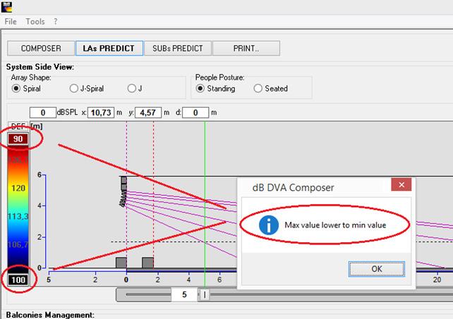
15 DVA Composer 5.0 performs several checks automatically to control if the values are correct. 15
.")
16 d) ADDED SPL CHART CONTROL PANEL With this new feature you can navigate into the spl chart. This allows to have a more accurate analysis of the spl shown. The line that show the coverage is fixed, you can navigate only through the spl bar (vertically). A) Fit the chart B) Shift up the chart C) Shift down the chart D) Zoom In E) Zoom Out 16
 border the requested coverage, but the graph display entire spl values from zero meters to the max coverage requested. In the row Freq.")
17 e) IMPROVED MULTI-FREQUENCY DISPLAY Now, Dva Composer 5.0 have this important feature, it allows to show in the spl chart nine frequencies (third octave) at the same time. In the chart two vertical bars (green and red) border the requested coverage, but the graph display entire spl values from zero meters to the max coverage requested. In the row Freq. we have a flag to enable the frequency, the frequency s value and the hold button to freeze the line plotted on the chart. In the db SPL row is shown, in the first cell, the dbspl values at the frequencies enabled. This value is correspondent at the position of the cursor on the chart. When the hold button is enabled, under this button it will show the value of the curve frozen to compare with the actual curve at the same frequency. N.B. it s possible to enable only one hold button at the same time. At the end of the db SPL row is shown the position in meters of the cursor into the coverage range. 17
18 f) IMPROVED THE SUBWOOFER SPL CALCULATION In DVA Composer 5.0 it s been inserted the real frequency response curve of every subwoofers. g) SUBWOOFER DELAY MANAGEMENT As Shown in picture you can choose the delay calculation mode for end fire setup. In fact, if your system is equipped of an external processor, the DVA Composer give you the possibility to set the delay mode on EXT PROC. (Priority will be given to the attenuation frequency and to the distance between the subwoofers). In ON BOARD mode the delay will be calculated according to step allowed by the internal processor of our subwoofers 18

![ADVANCED SETTINGS Clicking on Line array setting checkbox [1.3] you can modify the gap between the two line array systems and the gap between the eventual Left\Right subwoofers clusters.](/docs-images/87/95397919/images/19-2.jpg "In Stage setting it s possible to set the stage dimensions: height, width and depth of the stage [1.4]. Enabling Framework setting you can choose between truss-layers or horizontal-truss [1.5].")
19 4. COMPOSER SECTION STANDARD SETTINGS In Standard settings section you can quickly set up your scenario. You just have to insert: the height of your system as flybar vertical position [1.1] venue settings: start coverage and end coverage positions [1.2] If you don t need any special settings you can skip to Section LINE MODULES. ADVANCED SETTINGS Clicking on Line array setting checkbox [1.3] you can modify the gap between the two line array systems and the gap between the eventual Left\Right subwoofers clusters. In Stage setting it s possible to set the stage dimensions: height, width and depth of the stage [1.4]. Enabling Framework setting you can choose between truss-layers or horizontal-truss [1.5]. If you change something you can click on UPDATE Current System [1.6] to apply the changes. 19


20 SYSTEM MODELS In the System Models column on the right you can find the complete list of DVA products, in terms of: flybars, line array speakers, subwoofers. Before adding the modules you have to choose between one of the two available flybars, DRK10 [1.7] or DRK20 [1.8]. At this point you can add the modules by just double-clicking on the relevant box or inputting the total number of modules you have and then pressing Enter button. Instantly the chosen modules will appear on the right graph window. TESTED CONFIGURATIONS In the drop-down box at the top you can choose from a set of tried and tested configurations of T4 and T12 [1.9] Time after time dbtechnologies will release more tested configurations to help users having the best results they can reach with their systems. ALARMS If the configuration is a good one, the Configuration check alarm will be green, otherwise this label will be yellow and Configuration not recommended will appear. 20

21 5. LINE ARRAY SECTION Now click on LAs PREDICT button. PREDICT VIEW On the first graph you can see the actual prediction of your system, based on the data you entered on the previous page. You can modify the angle of the ground [2.1], or add up to three balconies and modify them in terms of dimensions and inclination [2.2]. The software will update all the data in real time. If you prefer a different coverage, you can either go back to the first page and modify the coverage section, or simply move the cursors under the graph. You can choose among three different shape modes [2.3]: Spiral: the shape will be rounded like a spiral J: the first modules will be in straight position to cover longer distances. J-Spiral: a hybrid solution, including spiral and J shapes. This configuration works for every situation. Also, it s possible to choose between standing or seated audience [2.4]. Clicking on SPL button [2.5] (after having set the evaluation frequency) the sound pressure level field will appear on the graph. With the mouse you can go around the graph and the SPL label [2.6] will show the RMS power at that point. And also, clicking on the graph you could use a ruler to measure the distances [2.7]. 21


22 MANUAL MODE This feature allows you to change the angles between each module and the inclination of the flybar. You can change them just selecting the line coming out from a single module [2.8] By clicking and holding it, the software will display every available trajectory for the module [2.9], and with a simple drag you can change the box inclination [2.10]. Note that the software applies the changes in real time, and you can instantly check mechanical safety and frequency response of the system. At the time you enter in manual mode, the configuration check alarm turns yellow [2.11], and EQs of all modules are frozen to the last configuration provided by the software (Spiral, J, or J-Spiral shape). As manual mode is set, you can manually change EQs presets just in the line array datas, from there you can choose between some different appropriate EQ presets, according to the total number of cabinets of the array [2.12]. 22

, for each module in terms of: Mechanical angle to be used [2.")
23 LINE ARRAY SPL VIEW On the section shown in the picture you can see the power of your system depending on the distance and the chosen frequency. That s the fastest way to understand how the SPL coverage works at ear-height, without clicking on SPL button on the graph above. You can hold one of the curves and compare it with new ones given from different setups or different frequencies. SYSTEM DATA In the right window you can see all the information relating to the system (Picture 6), for each module in terms of: Mechanical angle to be used [2.14] Eq preset to be set up with the rotary encoder on the amplifier module [2.15] (you can modify EQ Presets only in Manual Mode ) Speakerbox model [2.16] Speakerbox sector affiliation: straight or curved [2.17] Weight of the module [2.18] Delay of the module [2.19] 23
![FLYBAR VIEW In this window you can find flybar information (Picture 7): Angle of flybar [2.20]. Holes where pivot has to be attached [2.21]. Pivot position [2.](/docs-images/87/95397919/images/24-0.jpg "21]: please note that dbtechnologies DRK20 pivot is asymmetrical; this for doubing the number of available suspension points for a more precise aiming of the system.")

24 FLYBAR VIEW In this window you can find flybar information (Picture 7): Angle of flybar [2.20]. Holes where pivot has to be attached [2.21]. Pivot position [2.21]: please note that dbtechnologies DRK20 pivot is asymmetrical; this for doubing the number of available suspension points for a more precise aiming of the system. Thus it s important to know the right position of the vertical side of this item. The options are two: vertical side to front or vertical side to back. Capacity of the flybar [2.22]: that s the maximum weight which flybar can support. Total weight of the current speaker boxes system [2.22]. Total weight of the current system, including flybar weight [2.22]. If the total weight of the boxes exceeds flybar capacity, the Mechanical safety alarm, will turn to red, in order to indicate this fact [2.20]. If the shape of the array is rot reachable with the available pinpoints of the flybar, the alarm will turn again to red [2.19]. The obvious aim to rig up a system in safety condition, is to have a green alarm [2.18]; however, the simulation software can work even if the weight exceeds the maximum recommended one, but in this case the safety is compromised. 24

25 6. SUBWOOFER SECTION On Subwoofer section you can manage your subwoofers setup SUBWOOFERS CONFIGURATIONS VIEW First of all you can choose between six available configurations: Left-Right [3.1]: the subwoofers will be placed under the two line array columns. Center [3.2]: the subwoofers will be placed at the center between the two line array columns. In this case the central audio channel from the mixer is needed. Left-Center-Right [3.3]: The subwoofers will be distributed between left-right and central positions. In this case, the central audio channel from the mixer is required in addition to left and right signals. Line [3.4]: the subs will be placed along a line, with different distances, to give the more powerful SPL response on the front/back and to attenuate the SPL on the sides. For this configuration, the central audio channel from the mixer is required; you can also connect the left ones to the left channel and the right ones to the right channel, but the results will be not the same as using the central signal. Cardioid [3.5]: the subs will be positioned in cardioid configuration to preserve the maximum power on the front and to attenuate the SPL on the back. If there is just one column, the central audio channel is required (L+R sum), but if there is an even number of columns, leftright channels can be used for central-left / central-right columns. The results in coherence of the low frequency dispersion wouldn t be of course the same as using a central audio channel, but the system will still work. End Fire [3.6]: the subwoofers will be placed in end-fire configuration and gaps/delays will be indicated in the lists on the right. As for Cardioid configuration, it s better to feed this cluster with a mono audio channel (L+R sum), even if the system can work (for even subs numbers) with left-right channels connected to left-right subwoofers. 25
26 For every configuration you can choose among different dispositions, for both left-right and central channel [3.11]. Please note that the first number means the number of columns and the second one (the one in brackets) is the number of subs in each column (example: 4(2) means a disposition in 4 columns of 2 sub each. Total: 8 subs). If you have two different models of subwoofers, you can also modify the positioning moving one model from central to left-right position and vice versa, just clicking on Invert [3.12]. SYSTEM FRONTLINE VIEW if you need the line array to be moved forwards or backwards from its starting position you can use the cursors on Line Array section below [3.7]. You can also write the position and press Enter to get the same result. The same goes for the position of the subwoofers [3.8]: you just have to move them with the L-R channels and C-channel. You can also link the channels and move them all together. Attenuation Frequency [3.8] is available for Cardioid and End-Fire configurations. Opening Angle [3.9] is available only for Line setups. Here you can choose among some opening angles to set the proper line configuration with the number of subwoofers you have. X-over frequency can be set up by drop-down menus [3.10]. Note that moving frontlines involves changing in delays for tops and subs phase alignment. Please always check delay check alarm on the top of the screen in order to have information about this issue. 26
![SUBWOOFERS SPL VIEW The graph below (Picture 9) shows the sound pressure level field for the chosen configurations. You just have to choose the evaluation frequency [3.14] and press the SPL button [3.](/docs-images/87/95397919/images/27-0.jpg "15]. With the cursor you can go around the graph and the SPL label will show the peak power at that point [3.16].")
![Also here a ruler is available just clicking over the graph and moving the mouse around the power field [3.17].](/docs-images/87/95397919/images/27-2.jpg "The Polar Pattern box is available only when DVA S2585N Cardioid Subwoofers are selected.")
27 SUBWOOFERS SPL VIEW The graph below (Picture 9) shows the sound pressure level field for the chosen configurations. You just have to choose the evaluation frequency [3.14] and press the SPL button [3.15]. With the cursor you can go around the graph and the SPL label will show the peak power at that point [3.16]. Also here a ruler is available just clicking over the graph and moving the mouse around the power field [3.17]. The Polar Pattern box is available only when DVA S2585N Cardioid Subwoofers are selected. This dropdown menu let you choose polar pattern of the DVA S2585N subwoofers among Cardioid, Supercardioid and Hypercardioid. [3.18]. SUBWOOFERS DATA On the left of this chart, there is the complete list of the subwoofers set, with all data for the chosen configuration. X-over frequency [3.19] Delay of each sub [3.20] (if the subs are placed so that the delays have to be set on the line arrays, the Delay checkbox will change from green to yellow and Delays to line array will appear in it). Phase [3.21]: phase of each sub: 0 or 180 for phasereverse. Verse of the subwoofer [3.22]: indicates the position of the front side of each subwoofer; it means that if the subwoofer has to be physically rotated by 180, BACK will appear on this column, otherwise it will say FRONT. Subwoofer model [3.23]. Position of the subs frontline [3.24] (in case of endfire configuration. it shows the position of the back subwoofers frontline) measured from the reference frontline (normally that s the stage frontline). Gap between the subwoofers frontlines [3.25] in case of end-fire configuration. This measure is taken considering the gap front-to-front of the two subs frontlines. 27


28 7. PRINTOUT SECTION On Printout section you can print your setup. PROJECT INFO Before printing the project, you can add some info about your event and you can also write down some notes about your setup. After pressing Print Preview button the software will calculate all data you inserted and it will show a preview of your printout. PRINT PREVIEW In Print preview you can see the three pages created by the DVA Composer, clicking on the buttons on the top of the window [4.6]. Then you can select your printer [4.4] or your PDF creator software and at the end click on Printout button [4.5] to get the printout of the setup. 28
29 USER SHOULD NEVER APPLY A LOAD THAT EXCEEDS THE WORKING LOAD LIMITS OF ANY RIGGING COMPONENTS OR EQUIPMENT HERE PRESENTED. DESIGN, CALCULATION, INSTALLATION, TESTING AND MAINTAINANCE OF SUSPENSION AND STACK SYSTEMS FOR AUDIO EQUIPMENT MUST BE PERFORMED ONLY BY QUALIFIED AND AUTHORIZED PERSONNEL. AEB INDUSTRIALE S.R.L. DENIES ANY AND ALL RESPONSIBILITY FOR IMPROPER INSTALLATIONS, IN THE ABSENCE OF SAFETY REQUIREMENTS. 29

30 Features, specification and appearance of products are subject to change without notice. dbtechnologies reserves the right to make changes or improvements in design or manufacturing without assuming any obligation to change or improve products previously manufactured. A.E.B. Industriale Srl Via Brodolini, 8 Località Crespellano VALSAMOGGIA BOLOGNA (ITALIA) Tel Fax info@dbtechnologies-aeb.com 30
dbtechnologies QUICK REFERENCE
 dbtechnologies QUICK REFERENCE 1 DVA Composer Ver3.1 dbtechnologies What s new in version 3.1 COMPOSER WINDOW - DVA T8 line array module now available in the System Models window. - Adding modules in the
Con o t n e t n e t n s t
 Contents Page Item 3 Safety Warnings 4 Glossary 5 Attachment and Removal of Caster Frames 6 Line Array Element Attachment 7 Angle Selection 8 Rigging Frame (Bumper) 9 Electrical connection 10 System Mounting
SR-D8-M, SR-D8-S. (Ver ) SOFTWARE INSTRUCTIONS
 SOFTWARE INSTRUCTIONS") SOFTWARE INSTRUCTIONS active l ine array speak er SYStems SR-D8-M, SR-D8-S (Ver. 1.1.1) Thank you for purchasing TOA's Active Line Array Speaker Systems. Please carefully follow the instructions in this
SOFTWARE INSTRUCTIONS active l ine array speak er SYStems SR-D8-M, SR-D8-S (Ver. 1.1.1) Thank you for purchasing TOA's Active Line Array Speaker Systems. Please carefully follow the instructions in this
D-901 PC SOFTWARE Version 3
 INSTRUCTION MANUAL D-901 PC SOFTWARE Version 3 Please follow the instructions in this manual to obtain the optimum results from this unit. We also recommend that you keep this manual handy for future reference.
MAD A-Series...Flat Panel Surface Planar Arrays
 HPV TECHNOLOGIES, Inc. 17752 Fitch Irvine, California 92614 MAD A-Series...Flat Panel Surface Planar Arrays...Concert Sound at it s Finest! Flat Panel Surface Planar Arrays describe a new speaker technology
LIVERPOOL TLX43. Custom-Engineered Drivers
 Compact 2 way line array element for portable and fixed installation application 15 Watts continuous, 6 Watts peak power Ideal for FOH, center cluster, offstage fill, stereo in-fill or distributed fill
REMOTE SOFTWARE USER GUIDE V1.0
 REMOTE SOFTWARE USER GUIDE V1.0 TRAINING MANUAL version 1.0 Table of Contents 1. Prerequisites...1 2. Network...1 2. Kontrol operation...2 2.1 First time run Network selection...2 3. Show Setup...3 3.1
POSITIONING SUBWOOFERS
 POSITIONING SUBWOOFERS PRINCIPLE CONSIDERATIONS Lynx Pro Audio / Technical documents When you arrive to a venue and see the Front of House you can find different ways how subwoofers are placed. Sometimes
Operating Instructions
 Operating Instructions HAEFELY TEST AG KIT Measurement Software Version 1.0 KIT / En Date Version Responsable Changes / Reasons February 2015 1.0 Initial version WARNING Introduction i Before operating
VTX V25-II Preset Guide
 VTX V25-II Preset Guide General Information: VTX V25-II Preset Guide Version: 1.1 Distribution Date: 10 / 11 / 2016 Copyright 2016 by Harman International; all rights reserved. JBL Professional 8500 Balboa
TI 385 (4.0 EN) d&b Line array design, ArrayCalc V7.x
 d&b Line array design, ArrayCalc V7.x") TI 385 (4.0 EN) d&b Line array design, ArrayCalc V7.x Contents 1. Introduction...3 2. The J-Series line array...3 2.1 Number of cabinets required...3 2.2 J-SUB subwoofer setup...3 2.2.1 J-SUB ground stacks...4
TI 385 (4.0 EN) d&b Line array design, ArrayCalc V7.x Contents 1. Introduction...3 2. The J-Series line array...3 2.1 Number of cabinets required...3 2.2 J-SUB subwoofer setup...3 2.2.1 J-SUB ground stacks...4
USER MANUAL FOR DDT 2D. Introduction. Installation. Getting Started. Danley Design Tool 2d. Welcome to the Danley Design Tool 2D program.
 USER MANUAL FOR DDT 2D ( VERSION 1.8) Welcome to the Danley Design Tool 2D program. Introduction DDT2D is a very powerful tool that lets the user visualize how sound propagates from loudspeakers, including
ivw-fd133 Video Wall Controller MODEL: ivw-fd133 Video Wall Controller Supports 3 x 3 and 2 x 2 Video Wall Array User Manual Page i Rev. 1.
 MODEL: ivw-fd133 Video Wall Controller Supports 3 x 3 and 2 x 2 Video Wall Array User Manual Rev. 1.01 Page i Copyright COPYRIGHT NOTICE The information in this document is subject to change without prior
MaxView Cinema Kit Quick Install Guide
 SYSTEM SETUP The MaxView will work at any of the following display settings: INSTALLATION MaxView Cinema Kit Quick Install Guide Step 1 - Turn off your computer. Disconnect your monitor s VGA cable from
Portable Speakers. 2,500 Watt 2 Way 8" Powered Loudspeaker with KLARK TEKNIK DSP Technology, Speaker Modelling and ULTRANET Networking
 2 way full range loudspeaker for portable PA and installation applications 2,5 Watt power featuring KLARK TEKNIK Class-D technology KLARK TEKNIK Digital Signal Processing for total system control Speaker
AT450SAW Programmable Selective Amplifier
 AT450SAW Programmable Selective Amplifier LEMELETTRONICA srl Via Grezze 38 25015 Desenzano del Garda (BS) ITALY Tel. +39 030-9120006 Fax +39 030-9123035 www.lemelettronica.it Technical Specifications
Portable Speakers. 2,500 Watt 2 Way 15" Full Range Powered Loudspeaker with KLARK TEKNIK DSP Technology and ULTRANET Networking
 2 way full range powered loudspeaker for portable PA applications 2,5 Watt power featuring KLARK TEKNIK Class-D technology KLARK TEKNIK Digital Signal Processing for total system control ULTRANET digital
ivw-fd122 Video Wall Controller MODEL: ivw-fd122 Video Wall Controller Supports 2 x 2 Video Wall Array User Manual Page i Rev. 1.
 MODEL: ivw-fd122 Video Wall Controller Supports 2 x 2 Video Wall Array User Manual Rev. 1.01 Page i Copyright COPYRIGHT NOTICE The information in this document is subject to change without prior notice
SiS 2.0 User guide. Rev. 2.2
 SiS 2.0 User guide Rev. 2.2 COPYRIGHT INFORMATION The information in this user s guide and in the PC programme attached is subject to royalties, being these rights represented by FTE Maximal firm (hereafter
LavryBlack Series Model DA10 Digital to Analog Converter
 LavryBlack Series Model DA10 Digital to Analog Converter Lavry Engineering, Inc. P.O. Box 4602 Rolling Bay, WA 98061 http://lavryengineering.com email: techsupport@lavryengineering.com January 14, 2008
Quick Start Guide. Soundcraft Si Series Quick Start Guide Issue 1010
 Quick Start Guide Soundcraft Si Series Quick Start Guide Issue 1010 Page 1 INTRODUCTION IMPORTANT Please read this manual carefully before using your mixer for the first time. Firstly, thanks for choosing
NuQ102-AN-WH. Portable Speakers. 600 Watt 2 Way 10" Full Range Powered Loudspeaker with KLARK TEKNIK DSP Technology and ULTRANET Networking (White)
") 2 way full range powered loudspeaker for portable PA and installation applications 6 Watt power featuring KLARK TEKNIK Class-D technology KLARK TEKNIK Digital Signal Processing for total system control
2 way full range powered loudspeaker for portable PA and installation applications 6 Watt power featuring KLARK TEKNIK Class-D technology KLARK TEKNIK Digital Signal Processing for total system control
Linkage 3.6. User s Guide
 Linkage 3.6 User s Guide David Rector Friday, December 01, 2017 Table of Contents Table of Contents... 2 Release Notes (Recently New and Changed Stuff)... 3 Installation... 3 Running the Linkage Program...
ARIS EXPLORER 1200 GETTING STARTED
 ARIS EXPLORER 1200 GETTING STARTED Table of Contents 1 INTRODUCTION 2 WHAT S IN THE BOX 3 HOOKING UP THE SONAR 4 ARIScope SOFTWARE 5 CAPTURING QUALITY IMAGES 6 COMPUTER REQUIREMENTS 7 WARRANTY INFORMATION
THE FROG SERIES OPERATING MANUAL
 THE FROG SERIES OPERATING MANUAL THE FROG SERIES OPERATING MANUAL If a portable or temporary three phase mains supply is used to power this desk, we recommend that the desk mains plug is removed before
HD ENCODULATOR TM, SD ENCODULATOR TM LUMANTEK
 Revision Number: 1.0.0 Distribution Date: June 2017 Copyrights Notice Copyright : 2006-2017 LUMANTEK Co., Ltd. All Rights Reserved. This document contains information that is proprietary to LUMANTEK. CO.,
Warranty and Registration. Warranty: One Year. Registration: Please register your product at Port, or. or Windows.
 7 7 Port, or or Windows Port Warranty and Registration Warranty: One Year Registration: Please register your product at www.aitech.com 2007 AITech International. All rights reserved. WEB CABLE PLUS PC-TO-TV
Field Test 2. Installation and operation manual OPDAQ Installation and operation manual
 Field Test 2 Installation and operation manual OPDAQ 17.08.25 Installation and operation manual January 2016 How to get copies of OpDAQ technical publications: 53, St-Germain Ouest Rimouski, Québec Canada
Xpedition Layout for Package Design. Student Workbook
 Student Workbook 2017 Mentor Graphics Corporation All rights reserved. This document contains information that is trade secret and proprietary to Mentor Graphics Corporation or its licensors and is subject
Wireless Studio. User s Guide Version 5.1x Before using this software, please read this manual thoroughly and retain it for future reference.
 4-743-161-12 (1) Wireless Studio User s Guide Version 5.1x Before using this software, please read this manual thoroughly and retain it for future reference. DWR-R01D/R02D/R02DN/R03D 2018 Sony Corporation
with the Field-IQ Crop Input Control System
 with the Field-IQ Crop Input Control System Quick Reference Card CONNECTING THE SYSTEM Ag25 GNSS antenna (P/N 68040-OOS) TNC/TNC right-angle cable (P/N 50449) Cable assembly, display to Field-IQ (P/N 50449)
OPERATION MANUAL. FA-9600 LUT-Converter. Version Higher
 OPERATION MANUAL FA-9600 LUT-Converter Version 1.0.0 - Higher Software License Agreement This Software License Agreement is a legally binding agreement between you ( User ) and FOR-A Company Limited (
feno before light and beyond
 User Manual Multi 4 Control Version 2.0 feno GmbH, Kolpingring 22, 82041 Oberhaching, Germany P +49 89 613725 30, F +49 89 613725 50 email@feno.com, www.feno.com This manual and the associated software
Using the BHM binaural head microphone
 11/17 Using the binaural head microphone Introduction 1 Recording with a binaural head microphone 2 Equalization of a recording 2 Individual equalization curves 5 Using the equalization curves 5 Post-processing
AT47SAW Programmable Selective Amplifier
 AT47SAW Programmable Selective Amplifier LEMELETTRONICA srl Via Grezze 38 25015 Desenzano del Garda (BS) ITALY Tel. +39 030-9120006 Fax +39 030-9123035 www.lemelettronica.it Technical Specifications N
Crescent Walls User Manual
 HDMI-8x8 Crescent Walls User Manual COPYRIGHT and TRADEMARK All rights reserved by APANTA LCC, Porland, Oregon, USA. No part of this document may be reproduced in any form or by any means without written
for the Epson Stylus Pro 4000 User s Guide
 for the Epson Stylus Pro 4000 User s Guide All rights reserved. No part of this publication may be reproduced, stored in a retrieval system, or transmitted in any form or by any means, electronic, mechanical,
NOTICE. The information contained in this document is subject to change without notice.
 NOTICE The information contained in this document is subject to change without notice. Toontrack Music AB makes no warranty of any kind with regard to this material, including, but not limited to, the
V4.7 Software Quick Start Guide
 V4.7 Software Quick Start Guide INTRODUCTION TO V4.7 The 4.7 software update for the Vi Series includes a major update to the functionality of the Vi4 console in particular, bringing a new level of power
USB Mini Spectrum Analyzer User s Guide TSA5G35
 USB Mini Spectrum Analyzer User s Guide TSA5G35 Triarchy Technologies, Corp. Page 1 of 21 USB Mini Spectrum Analyzer User s Guide Copyright Notice Copyright 2011 Triarchy Technologies, Corp. All rights
NuQ152-AN ## ## Portable Watt 2 Way 15" Full Range Powered Loudspeaker with KLARK TEKNIK DSP Technology and ULTRANET Networking
 Product Information Document 2 way full range powered loudspeaker for portable PA and installation applications 2,5 Watt power featuring KLARK TEKNIK Class-D technology KLARK TEKNIK Digital Signal Processing
PSP Master Comp. Stereo Mastering Compressor
 PSP Master Comp Stereo Mastering Compressor By using this software you agree to the terms of any license agreement accompanying it. PSP, the PSP logo, PSP MasterComp, and It s the sound that counts! are
Liquid Mix Plug-in. User Guide FA
 Liquid Mix Plug-in User Guide FA0000-01 1 1. COMPRESSOR SECTION... 3 INPUT LEVEL...3 COMPRESSOR EMULATION SELECT...3 COMPRESSOR ON...3 THRESHOLD...3 RATIO...4 COMPRESSOR GRAPH...4 GAIN REDUCTION METER...5
iq15 Portable 2500 Watt 2 Way 15" Powered Loudspeaker with KLARK TEKNIK DSP Technology, Speaker Modelling and ULTRANET Networking
 2 way full range loudspeaker for portable PA and installation applications 2,5 Watt power featuring KLARK TEKNIK Class-D technology KLARK TEKNIK Digital Signal Processing for total system control Speaker
DM1624, DM1612, DM812
 Installation Guide Hardware and Software DM Series Digital Processors models DM1624, DM1612, DM812 LECTROSONICS, INC. 1 Installation Specific Information Only This guide covers only installation related
2013, 2014 Hewlett-Packard Development Company, L.P.
 User Guide 2013, 2014 Hewlett-Packard Development Company, L.P. The only warranties for HP products and services are set forth in the express warranty statements accompanying such products and services.
Mackie Control and Cubase SX/SL
 Mackie Control and Cubase SX/SL - 1 - The information in this document is subject to change without notice and does not represent a commitment on the part of Steinberg Media Technologies AG. The software
TOMELLERI ENGINEERING MEASURING SYSTEMS. TUBO Version 7.2 Software Manual rev.0
 TOMELLERI ENGINEERING MEASURING SYSTEMS TUBO Version 7.2 Software Manual rev.0 Index 1. Overview... 3 2. Basic information... 4 2.1. Main window / Diagnosis... 5 2.2. Settings Window... 6 2.3. Serial transmission
VENUS X1PRO-E Quick Start
 VENUS X1PRO-E Quick Start 4K input support in DP, HDMI and Dual Link DVI Support 8K x 1K, 4K x 2K Seamless Splicing EDID management Modular 2K input: Three slots for 2K input options 2K-2K and/or 4K-2K
ASSEMBLY AND CALIBRATION
 CineMax Kit ASSEMBLY AND CALIBRATION www.cineversum.com Ref: T9003000 Rev: 01 Part. No.: R599766 Changes CineVERSUM provides this manual as is without warranty of any kind, either expressed or implied,
System Requirements SA0314 Spectrum analyzer:
 System Requirements SA0314 Spectrum analyzer: System requirements Windows XP, 7, Vista or 8: 1 GHz or faster 32-bit or 64-bit processor 1 GB RAM 10 MB hard disk space \ 1. Getting Started Insert DVD into
SAT IF distribution system
 7. Technical specifications Type cs43 RF input frequency range pr. 50-350 MHz inputs number 4 level pr. 55...88 dbµv 60...93 dbµv symbol rate 3 45 Ms/s return loss/impedance > 0 db/75 Ω LNB powering/control
TI 385 d&b Line array design 10.1 en
 385 TI 385 d&b Line array design 10.1 en General information TI 385 d&b Line array design Version: 10.1 en, 06/2018, D5385.EN.10 Copyright 2018 by d&b audiotechnik GmbH; all rights reserved. d&b audiotechnik
Immersive. 6.5HD Line Arrays. Description: Features: Applications:
 Immersive HD 6.5HD Line Arrays Description: Utilizing our Model 6.5HD module as the building block for customized Immersive Array s. Systems can be designed for any fixed application or venue with up to
ATS50SAW Programmable Selective Amplifier
 ATS50SAW Programmable Selective Amplifier Technical Specifications N Input BI/BII (40 108 MHz) 1 N Input BIII/DAB (170 320 MHz) 1 N AUX input (40 860 MHz) 1 N Programmable Input UHF (470 790 MHz) 4 N IF-SAT
OPERATING GUIDE. HIGHlite 660 series. High Brightness Digital Video Projector 16:9 widescreen display. Rev A June A
 OPERATING GUIDE HIGHlite 660 series High Brightness Digital Video Projector 16:9 widescreen display 111-9714A Digital Projection HIGHlite 660 series CONTENTS Operating Guide CONTENTS About this Guide...
FOUR CHANNEL USB RECORDER PCRU01. User manual. Table of Contents
 FOUR CHANNEL USB RECORDER PCRU01 User manual Table of Contents Features 2 Specifications 2 hardware 2 software: 2 system requirements 2 Software installation 2 SAFETY and WARNINGS 3 Warranty 3 Connections
Element 78 MPE-200. by Summit Audio. Guide To Operations. for software version 1.23
 Element 78 MPE-200 by Summit Audio Guide To Operations for software version 1.23 TABLE OF CONTENTS IMPORTANT SAFETY AND GROUNDING INSTRUCTIONS COVER 1. UNPACKING AND CONNECTING...3 AUDIO CONNECTIONS...4
USER MANUEL. SNIPE 2 Ref R13
 USER MANUEL SNIPE 2 Ref. 0141317R13 Contents 1. General Information 1-1. Introduction 1-2. Proper use and operation 1-3. Safety notes......... 2 3 3 2. Contents 2-1. Accessory included 2-2. Name of parts......
SPL Analog Code Plug-ins Manual Classic & Dual-Band De-Essers
 SPL Analog Code Plug-ins Manual Classic & Dual-Band De-Essers Sibilance Removal Manual Classic &Dual-Band De-Essers, Analog Code Plug-ins Model # 1230 Manual version 1.0 3/2012 This user s guide contains
Features/Specifications
 Introduction Thank you for purchasing the DD Audio DSI-1(Digital Signal Integrator). The DSI-1 is a feature rich audio signal processor that will allow you to precisely tune the acoustics of your car audio
VocALign Project 3 (AAX) For Pro Tools 11 & 12. User s Manual. Manual Version 3.3. Compatible with Apple Macintosh and Microsoft Windows systems
 For Pro Tools 11 & 12. User s Manual. Manual Version 3.3. Compatible with Apple Macintosh and Microsoft Windows systems") VocALign Project 3 (AAX) For Pro Tools 11 & 12 Compatible with Apple Macintosh and Microsoft Windows systems User s Manual Manual Version 3.3 VocALign_Project_3_AAX_Manual_33.doc 1 Synchro Arts Limited
VocALign Project 3 (AAX) For Pro Tools 11 & 12 Compatible with Apple Macintosh and Microsoft Windows systems User s Manual Manual Version 3.3 VocALign_Project_3_AAX_Manual_33.doc 1 Synchro Arts Limited
X-Sign 2.0 User Manual
 X-Sign 2.0 User Manual Copyright Copyright 2018 by BenQ Corporation. All rights reserved. No part of this publication may be reproduced, transmitted, transcribed, stored in a retrieval system or translated
Show Designer 3. Software Revision 1.15
 Show Designer 3 Software Revision 1.15 OVERVIEW... 1 REAR PANEL CONNECTIONS... 1 TOP PANEL... 2 MENU AND SETUP FUNCTIONS... 3 CHOOSE FIXTURES... 3 PATCH FIXTURES... 3 PATCH CONVENTIONAL DIMMERS... 4 COPY
DIGITAL SPEAKER MANAGEMENT UK
 DSM2-6mkII DIGITAL SPEAKER MANAGEMENT 170.659UK Features 96kHz sampling frequency, 32-bit A/D and D/A converter, 24-bit DSP processor Input channel: 6-band parametric EQ, Delay, Polarity Output channel:
A-ATF (1) PictureGear Pocket. Operating Instructions Version 2.0
 PictureGear Pocket. Operating Instructions Version 2.0") A-ATF-200-11(1) PictureGear Pocket Operating Instructions Version 2.0 Introduction PictureGear Pocket What is PictureGear Pocket? What is PictureGear Pocket? PictureGear Pocket is a picture album application
A-ATF-200-11(1) PictureGear Pocket Operating Instructions Version 2.0 Introduction PictureGear Pocket What is PictureGear Pocket? What is PictureGear Pocket? PictureGear Pocket is a picture album application
The BAT WAVE ANALYZER project
 The BAT WAVE ANALYZER project Conditions of Use The Bat Wave Analyzer program is free for personal use and can be redistributed provided it is not changed in any way, and no fee is requested. The Bat Wave
ADS Basic Automation solutions for the lighting industry
 ADS Basic Automation solutions for the lighting industry Rethinking productivity means continuously making full use of all opportunities. The increasing intensity of the competition, saturated markets,
Panaray MSA12X. Modular Steerable Array Loudspeaker. Design Guide
 Panaray MSA12X Modular Steerable Array Loudspeaker Design Guide Table of Contents Selecting Loudspeaker Models, Modules and Beam Patterns Is the MSA12X the Right Choice for the Application?... 4 Choosing
Instant 802.3af Gigabit Outdoor PoE Converter. Model: INS-3AF-O-G. Quick Start Guide
 Instant 802.3af Gigabit Outdoor PoE Converter Model: INS-3AF-O-G Quick Start Guide QUICK START GUIDE Introduction Thank you for purchasing the Ubiquiti Networks Instant 802.3af Gigabit Outdoor PoE Converter.
PCIe: EYE DIAGRAM ANALYSIS IN HYPERLYNX
 PCIe: EYE DIAGRAM ANALYSIS IN HYPERLYNX w w w. m e n t o r. c o m PCIe: Eye Diagram Analysis in HyperLynx PCI Express Tutorial This PCI Express tutorial will walk you through time-domain eye diagram analysis
ZYLIA Studio PRO reference manual v1.0.0
 1 ZYLIA Studio PRO reference manual v1.0.0 2 Copyright 2017 Zylia sp. z o.o. All rights reserved. Made in Poland. This manual, as well as the software described in it, is furnished under license and may
LM/TM-30xx, 31xx Series LCD Monitor User s Manual Rev. A0
 LM/TM-30xx, 31xx Series LCD Monitor User s Manual Rev. A0 FCC NOTICE This equipment generates, uses, and can radiate radio frequency energy and, if not installed and used in accordance with the instructions
PicoScope 2000 Series PC Oscilloscopes
 PicoScope 2000 Series PC Oscilloscopes User guide I PicoScope 2000 Series User Guide Table of Contents 1 Introduction...2...2 1 Overview...2 2 Safety symbols...3 3 Safety warning...3 4 FCC notice 5 CE
Data Loggers SL699, 703, 704 & 705. Impact Test Equipment Ltd & User Guide. User Guide
 Data Loggers SL699, 703, 704 & 705 Impact Test Equipment Ltd www.impact-test.co.uk & www.impact-test.com User Guide User Guide Impact Test Equipment Ltd. Building 21 Stevenston Ind. Est. Stevenston Ayrshire
Supplement to the Operating Instructions. PRemote V 1.2.x. Dallmeier electronic GmbH. DK GB / Rev /
 Supplement to the Operating Instructions PRemote V 1.2.x 1 DK 180.000.000 GB / Rev. 1.2.3 / 030416 PRemote V 1.2.x Copyright All rights reserved. This document may not be copied, photocopied, reproduced,
1. SAFETY & WARRANTY 2 2. WHAT IS CGM 3 3. SYSTEM SETUP (LINKING) Master to Group(s) Group to Channel(s) 3 4. CONNECT THE POWER 4
 Master to Group(s) Group to Channel(s) 3 4. CONNECT THE POWER 4") CGM CREATIVE MIXER 1. SAFETY & WARRANTY 2 2. WHAT IS CGM 3 3. SYSTEM SETUP (LINKING) 3 3.1. Master to Group(s) 3 3.2. Group to Channel(s) 3 4. CONNECT THE POWER 4 4.1. Which channel module should be powered
CGM CREATIVE MIXER 1. SAFETY & WARRANTY 2 2. WHAT IS CGM 3 3. SYSTEM SETUP (LINKING) 3 3.1. Master to Group(s) 3 3.2. Group to Channel(s) 3 4. CONNECT THE POWER 4 4.1. Which channel module should be powered
An AAX Plug-in. Version 1.05 December 7, 2013 LTD East 5th Street Superior, WI USA tel: fax:
 An AAX Plug-in OPERATOR'S MANUAL Version 1.05 December 7, 2013 LTD. 2117 East 5th Street Superior, WI 54880 USA tel: 715-398-3627 fax: 715-398-3279 www.cranesong.com 2013 Crane Song, LTD. Subject to change
Normal View JBL SRX800 Series
 Normal View JBL Series Normal View: SRX812P, SRX815P, and SRX835P Normal View: SRX818P and SRX828P The Normal Factory Panel is the default panel configuration. From here you will be able to quickly and
Manual Version Ver 1.0
 The BG-3 & The BG-7 Multiple Test Pattern Generator with Field Programmable ID Option Manual Version Ver 1.0 BURST ELECTRONICS INC CORRALES, NM 87048 USA (505) 898-1455 VOICE (505) 890-8926 Tech Support
DRM212 DRM215 DRM315 SPECIFICATIONS
 DRM212 DRM215 DRM315 DRM Series Professional Powered Loudspeakers deliver class-leading power via ultra-efficient Class-D amplifiers with next-gen protection and Power Factor Correction technology for
MIE 402: WORKSHOP ON DATA ACQUISITION AND SIGNAL PROCESSING Spring 2003
 MIE 402: WORKSHOP ON DATA ACQUISITION AND SIGNAL PROCESSING Spring 2003 OBJECTIVE To become familiar with state-of-the-art digital data acquisition hardware and software. To explore common data acquisition
VocALign Project LE For the Digidesign Pro Tools System
 VocALign Project LE For the Digidesign Pro Tools System Compatible with Apple Macintosh and Microsoft Windows systems User s Manual Manual Version 2.9 LE 1 Synchro Arts Limited 1995-2003 VocALign is a
With Latency Killer TM Technology. Model LK-Solo. HP Amp 2x2 Loop Thru Mixer
 With Latency Killer TM Technology Model LK-Solo HP Amp 2x2 Loop Thru Mixer Lavry Engineering, Inc. P.O. Box 4602 Rolling Bay, WA 98061 www.lavryengineering.com November 20, 2014 Rev 2.0 2 Table of Contents
SIDRA INTERSECTION 8.0 UPDATE HISTORY
 Akcelik & Associates Pty Ltd PO Box 1075G, Greythorn, Vic 3104 AUSTRALIA ABN 79 088 889 687 For all technical support, sales support and general enquiries: support.sidrasolutions.com SIDRA INTERSECTION
Statement SmartLCT User s Manual Welcome to use the product from Xi an NovaStar Tech Co., Ltd. (hereinafter referred to as NovaStar ). It is our great
. It is our great") LED Display Configuration Software SmartLCT User s Manual Software Version: V3.0 Rev3.0.0 NS110100239 Statement SmartLCT User s Manual Welcome to use the product from Xi an NovaStar Tech Co., Ltd. (hereinafter
LED Display Configuration Software SmartLCT User s Manual Software Version: V3.0 Rev3.0.0 NS110100239 Statement SmartLCT User s Manual Welcome to use the product from Xi an NovaStar Tech Co., Ltd. (hereinafter
PS User Guide Series Seismic-Data Display
 PS User Guide Series 2015 Seismic-Data Display Prepared By Choon B. Park, Ph.D. January 2015 Table of Contents Page 1. File 2 2. Data 2 2.1 Resample 3 3. Edit 4 3.1 Export Data 4 3.2 Cut/Append Records
VTAPE. The Analog Tape Suite. Operation manual. VirSyn Software Synthesizer Harry Gohs
 VTAPE The Analog Tape Suite Operation manual VirSyn Software Synthesizer Harry Gohs Copyright 2007 VirSyn Software Synthesizer. All rights reserved. The information in this document is subject to change
USER MANUAL. Vidifox Document Camera DV 480
 Vidifox Document Camera DV 480 USER MANUAL Please read this User Manual thoroughly before you use the document camera. Keep the CD-ROM in a convenient place so you can use it quickly if you need to. Please
Portable Speakers. 3,000 Watt 18" Powered Subwoofer with KLARK TEKNIK DSP Technology, Speaker Modelling and ULTRANET Networking
 Front loaded powered subwoofer for portable PA and installation applications power featuring KLARK TEKNIK Class-D technology KLARK TEKNIK Digital Signal Processing for total system control Speaker modelling
PLUGIN MANUAL. museq
 PLUGIN MANUAL museq Welcome! introduction SYSTEM REQUIREMENTS Please check all information on this topic here: https://plugin-alliance.com/en/systemrequirements.html ACTIVATION Details about the activation
Xsub v5.0 cardioid and supercardioid ground-stack array settings
 Cardioid subwoofer array settings Cardioid subwoofer arrays can be used to direct the output of an array of subwoofers in order to limit excessive amounts of bass in undesired locations. Cardioid arrays
DVISm. DVISm - Mini Digital Video Insertion System. Quick Start Guide. Patent Pending
 DVISm Patent Pending DVISm - Mini Digital Video Insertion System Quick Start Guide Although every effort has been taken to ensure the accuracy of this document it may be necessary, without notice, to make
XviewerEYE Video and Waveform Viewer Feature
 User s Manual 701992 XviewerEYE Video and Waveform Viewer Feature 3rd Edition Thank you for purchasing the XviewerEYE Video and Waveform Viewer Software. This manual, focused on Windows XP, explains features
USER MANUAL. 27" 2K QHD LED Monitor L27HAS2K
 USER MANUAL 27" 2K QHD LED Monitor L27HAS2K TABLE OF CONTENTS 1 Getting Started 2 Control Panel/ Back Panel 3 On Screen Display 4 Technical Specs 5 Troubleshooting 6 Safety Info & FCC warning 1 GETTING
install applications.
 Arrayable 2 way full range loudspeaker for installation applications Rotatable Dendritic waveguide with 9 H x V dispersion 2,5 Watt power featuring KLARK TEKNIK Class-D technology KLARK TEKNIK Digital
User Manual CC DC 24 V 5A. Universal Control Unit UC-1-E. General Information SET. Universal Control Unit UC-1 Of Central Lubrication PAUSE CONTACT
 Universal Control Unit UC-1-E User Manual General Information Universal Control Unit UC-1 Of Central Lubrication CC DC 24 V 5A / M 15 SL /MK 31 M Z 30 General Information Contents Universal Control Unit
Fully ly Automaticti. Motorised Satellite t TV System. User s manual REV
 REV. 1.0 Fully ly Automaticti Motorised Satellite t TV System User s manual Customer Help Line: 1300 139 255 Support Email: support@satkingpromax.com.au Website: www.satkingpromax.com.au www.satkingpromax.com.au
VocALign Project For the Digidesign Pro Tools System
 VocALign Project For the Digidesign Pro Tools System Compatible with Apple Macintosh and Microsoft Windows systems User s Manual Manual Version 2.9.1 1 Synchro Arts Limited 1995-2006 VocALign is a registered
ATHENS TCS122/96-AN. Install Speakers
 Product Information Document ATHENS TCS122/96-AN Arrayable 2 way full range loudspeaker for installation applications Rotatable Dendritic waveguide with H x V dispersion 2,5 Watt power featuring KLARK