VeriLUM 5.1. Color and Grayscale Video Display Calibration, Conformance Tracking, Acceptance Testing
|
|
|
- Marlene Fields
- 5 years ago
- Views:
Transcription
1 VeriLUM 5.1 Color and Grayscale Video Display Calibration, Conformance Tracking, Acceptance Testing IMAGE Smiths, Inc C Amaranth Drive, Germantown, MD Voice: Fax: Web: Technical Support : Neil@image-smiths.com
2 This User Guide describes installation and operation of VeriLUM Version 5.1. Revision Date: June, 2004 Copyright 1999 by IMAGE Smiths, Inc. All rights reserved. Copyright permission granted for display of the SMPTE Test Pattern Rev. 10/ 6/83 by the Society of Motion Picture and Television Engineers and for the CIE 1931 Chromaticity Diagram by Joe Kane Productions, Inc. Trademarks, service marks, and other registered names are hereby acknowledged to be the property of their owners: Adobe Systems, Inc.; DICOM; Gretag MacBeth, Inc.; Image Systems, Inc.; Matrox Electronic Systems, LTD; Microsoft Corporation; National Electrical Manufacturers Association; nvidia Corporation; Real Vision, Inc.; Sencore Electronics; Sequel Imaging Corporation; WIDE Corporation. Companies and organizations should be contacted for complete information regarding trademarks and other registrations. VeriLUM is compliant with year 2000 standards and will not be affected by dates occurring before, during, or after the year
3 Table of Contents Preface 1.0 Getting Started 1.1 System Requirements 1.2 Installing VeriLUM 1.3 Running VeriLUM 1.4 Uninstalling VeriLUM 2.0 Operating VeriLUM 2.1 Using VeriLUM for Acceptance Testing 2.2 Using VeriLUM for Calibration to a Luminance Response Model 2.3 Using VeriLUM for Conformance Tracking 2.4 Adjusting Color Temperature 2.5 Plotting Results 3.0 Technical Notes 3.1 White Level and Black Level Settings 3.2 Luminance Measuring Device Specifications 3.3 Number of Luminance Measurements 3.4 Data File Format for User Defined Luminance Response Model 3.5 Registry Entries and Downloadable Gamma Ramps 3.6 CIE Chromaticity Coordinates 3.7 Color Temperature 3.8 Using VeriLUM with Multiple Color Displays on a Desktop 4.0 Calibration Scenarios 4.1 One or More Grayscale Video Displays and Downloadable Gamma Ramp Video Card 4.2 One or More Color Video Displays and Downloadable Gamma Ramp Video Card 5.0 Creating User-Defined LCD Correction Factors 6.0 Using VeriLUM OptiGrayscale Characteristic Curve Files 3
4 Preface VeriLUM 5.1 is a tool for ensuring consistent color and grayscale video display performance. In the past this function has been the province of the video card vendors and the video display manufacturers. More recently the responsibility for assuring the quality of soft copy display has been placed exactly where hard copy quality assurance resides: in the hands of the end user. This means the end user must be able to make reproducible measurements of the video display performance and interpret and act on the results. Our goal is to make it easy and efficient to judge when a video display system is continuing to function normally or needs adjustment or replacement. NOTE: This version of VeriLUM is compatible with prior versions and works with the VeriLUM Color Dual Mode and VeriLUM Grayscale photometers. In addition, VeriLUM supports some photometers labeled with the name and/or logo of other companies. For example, some Sencore Electronics ColorPro III and ColorPro IV photometers are supported as are pods labeled by WIDE Corporation. If you have one of these supported pods, then all references herein to the VeriLUM pod also apply to the other pods. VeriLUM supports the whole range of Microsoft Windows operating systems and can be configured to work with the more complex desktop designs of Windows 2000 and Windows XP. When the VeriLUM Color Dual Mode pod is used, both CRT displays and LCD displays can be measured as well as both color and grayscale displays. Thus VeriLUM is applicable to a wider array of displays and is easier to use. VeriLUM also can use an auxiliary file to achieve a faster and more accurate DICOM Part 14 calibration on display devices which use a true color video card. The files are produced by IMAGE Smiths, Inc. and are named VeriLUM OptiGrayscale Characteristic Curve files. Each such file is specific to a particular display device and, when available, can be obtained from the Downloads page of IMAGE Smiths, Inc. website ( The file is unzipped and placed in the install folder for VeriLUM and then is available for use in calibrating that display device. This results in 256 distinct luminance values for the 256 driving levels and luminance response model chosen. This is accomplished by utilizing a sub-pixel modulation technique. Please see Section 6.0 for more detailed information on using this option. The current major issue is whether or not a particular video board is supported. That is, does VeriLUM properly address the gamma ramps on the video board. It is possible that changes to video cards, drivers, or display panels will invalidate the functioning of VeriLUM. In an attempt to avoid that situation, we have formed technology partnerships with several video controller manufacturers and will certify that VeriLUM works with their video cards, firmware, and drivers. Currently those partners include: Matrox Electronic Systems, Inc.; Image Systems Corporation; and Real Vision, Inc. A less formal arrangement exists with nvidia Corporation: we use the nvidia API to address the gamma ramps on most nvidia boards. VeriLUM works with other video cards but we are not able to certify that we are up-to-date on their latest firmware and drivers. If you have questions about a particular video card and display, please contact IMAGE Smiths, Inc. (Neil@image-smiths.com). Also note that we provide an unconditional 30-day money back guarantee to protect you against the possibility that VeriLUM does not work with your display and video card combination. 4
5 One use of VeriLUM is acceptance testing of a video display system prior to signing off on procurement paperwork. VeriLUM provides a quick visual check for the user. A SMPTE test pattern and a VeriLUM test pattern can be displayed on each video display that is part of the desktop. If the grayscale range and stability is adequate for each display, if the geometry and focus are acceptable, and if all of the displays have essentially the same lookand-feel, then the video system is ready for use. If one or more of the video displays is in need of adjustment then maintenance can be requested. For the quality assurance specialist interested in tracking consistent performance over time, a rapid set of measurements of the display luminance is made and an index is computed for each video display. These measurements take about 45 seconds per display and the history chart can be printed when hardcopy documentation is required. The computed index indicates how well the video system matches a specific luminance response model. Even if the natural gamma of the display is used, it is still possible to track the computed index, the white level, and the black level, over time. In addition, for color displays, the correlated color temperature and chromaticity coordinates of the white level and the luminance values for the red, green, and blue primaries are tracked. VeriLUM can be used to perform gamma correction in conformance with the DICOM Part 14 Grayscale Standard Display Function or a user specified gamma model or any other user-defined luminance response model. Loading a lookup table at system startup time is possible if a video board is used that has the facility for on-board gamma correction. When VeriLUM 5.1 is used with the Dual Mode pod, all CRTs and LCDs are supported when they are driven by video cards that VeriLUM supports. When VeriLUM 5.1 is used with the VeriLUM Grayscale or Color pod, then VeriLUM performs gamma correction on all CRTs but only on some LCD displays. For those specific displays, luminance measurements have been taken with a spotmeter and correction factors implemented in the VeriLUM software to account for the difference in luminance when the display is measured with a non-dual Mode VeriLUM photometer. A list of LCDs for which we have measured correction factors is included in the menu screen entitled VeriLUM Display Device. From this menu, you can choose the appropriate LCD display correction factors. Changes to the list of LCDs supported by VeriLUM are made when necessary. The current list and the most recent version of VeriLUM is always available on our website For color displays a technique is provided for adjusting the color temperature when the operating system and video card support downloadable gamma ramps. VeriLUM calculates adjustments for the red, green, and blue (RGB) relative gains in order to achieve a user-specified color temperature. A VeriLUM luminance pod must be connected to the PC each time the software is run. There are two different VeriLUM pods: wide-ranging grayscale, and color dual mode ; and there are two connector types: serial port (COM) and Universal Serial Bus (USB). The same software package works with both pod types and connector types. The grayscale pod can be used on color displays, but the chromaticity measurement features will not be available. The color dual mode pod provides chromaticity and luminance measurements on color and grayscale displays. The USB is not supported on systems using the Windows NT operating system. 5
6 Please note that, unlike most PC software packages, VeriLUM software can be installed on as many workstations as desired; no additional licenses are required. This allows a VeriLUM pod to be taken from workstation to workstation to perform measurements. The VeriLUM COM port pod attaches to a serial communications port on the PC and thus a simple extension cable from the serial port to the front of the PC can be used to minimize the aggravation of hunting around behind the PC for the proper connector. In summary, VeriLUM provides a simple, effective tool for performing calibration, conformance tracking, acceptance testing, and visual verification of a color or grayscale video display system. 6
7 1.0 Getting Started 1.1 System Requirements VeriLUM requires a personal computer (PC) running a Microsoft Windows NT 4.0, 2000, or XP Operating System; and a video card capable of at least 1024 X 768 pixels with a minimum of 256 colors (24- or 32-bit true color is highly recommended) or a grayscale video board with downloadable gamma ramps. Administrator privileges are required to install VeriLUM. 1.2 Installing VeriLUM VeriLUM software is shipped on a CD-ROM but may also be downloaded from our website. Double-click the VeriLUM51_Install.exe icon with the left mouse button. The installation script will verify the minimum system requirements, create the necessary folders and icons, install the program files and ancillary files, and update the registry. The install process uses the Microsoft Installer Technology. If the Installer Engine is not already on the PC, it will be included in the install process and it may be necessary to restart the PC during and/or after the install procedure. This User Guide is included on the CD in both Microsoft Word format and in Adobe Acrobat PDF format. Please print as many copies as you need. In addition, this User Guide is copied to the folder in which VeriLUM is installed so it is available on each PC where VeriLUM is used. The most recent revision of the VeriLUM software can always be downloaded from the IMAGE Smiths, Inc. website: Running VeriLUM [ Note: VeriLUM uses the left mouse button exclusively. Thus all references to clicking imply left mouse button clicks. ] After installing the VeriLUM software, connect a VeriLUM pod (grayscale or color dual-mode) to the PC. Auto-detection of the COM port is performed. If the pod has a USB connector, then Plug and Play should automatically detect and load the driver. If this does not occur, then point Windows to the install folder for VeriLUM (default: C:\Program Files\VeriLUM) and select the ChromaB.inf file. Click on Start/Programs/VeriLUM. Normally the VeriLUM main dialog box appears as shown in Figure 1 However, the first time VeriLUM is run, a configuration dialog box appears (see Figure 2). 7
8 The Configuration dialog box has two buttons in the upper right-hand corner that are used to select the display device being used and specify the desktop display configuration. See Figure 2A for the input required when a VeriLUM Color Dual Mode photometer is used. Essentially, it is sufficient to specify whether your display is a CRT or an LCD and whether it is grayscale or color. The Projector option is treated like an LCD. Figure 2B shows the choices available when you are using the wide-ranging grayscale pod or the older color pod. Here you must specify whether you are using a CRT or LCD display and, if an LCD, the correction factors to use based on the manufacturer and model of the LCD display. Also you must specify whether the CRT or LCD is grayscale or color. If you have an LCD flat panel display that matches one on the VeriLUM Display Device menu list, then select that device. Other flat panel vendors and models will be added in the future. You can also indicate that you have an LCD panel but do not want to use correction factors. If you measure your own correction factors (see Section 5.0) then you can choose to use them. In Windows 2000 and Windows XP, a more complex desktop is permitted. In addition to the rectangular array used in Windows NT, it is now possible to have a mix of color and grayscale displays, non-uniform rows and columns, and portrait and landscape modes. Using the Monitor Configuration options to configure the calibration choices may require some experimentation. Many video card vendors have a Windows 2000 or XP driver option to mimic the rectangular single handle to the desktop mode of Windows NT. If such an option is used then it must be noted in the VeriLUM Monitor Configuration Dialog (see Figure 2C). If using Windows NT, specify the number of video displays to be calibrated that comprise the desktop. This ensures that the video measurements are made in the center of each display and not the center of the desktop. For Windows 2000 and Windows XP it is not necessary to specify the number of displays. You can indicate how the minimum and maximum luminance values enter into the gamma correction scheme. The measured values can be used; a set of target values can be specified; or you can use the measured maximum and specify a target value for the contrast ratio (i.e. the ratio of maximum to minimum luminance). For CRTs, a percent surround value can be specified. This value is used to define the surround for all luminance measurements; in particular, all luminance measurements used in determining the DICOM Part 14 gamma correction lookup table. The default value is 20%. LCDs do not have a veiling glare component to the luminance and thus the percent surround value is set to zero for LCDs. This speeds up the luminance measuring process. When you click the OK button the VeriLUM application will exit to complete the initialization and the VeriLUMOnOff application will be launched. VeriLUMOnOff is a task bar application that provides easy access to enabling and disabling the gamma correction. In addition, there is a button for running VeriLUM without the pod being attached. Note that when the gamma model has been chosen as the luminance response model for calibration VeriLUMOnOff permits a user 8
9 to specify a different gamma to be used and the choice takes effect without re-measuring the characteristic curve of the display. The EXIT button returns control to the desktop. All other buttons are described in Section 2, Operating VeriLUM. 1.4 Uninstalling VeriLUM To remove VeriLUM, use the Control Panel Add/Remove Programs function. All files and icons and registry entries created as a part of the install process will be removed. Files created during the operation of the VeriLUM software will not be removed. In particular, the VeriLUM.Pref file will remain in the install folder. Manually deleting these files is recommended. If it is desired to re-define the desktop it is not necessary to un-install and re-install VeriLUM. You can delete the VeriLUM.Pref file from the VeriLUM install folder and then create it again by running VeriLUM and answering the questions in the Configuration Screen. 9

10 FIGURE 1. VeriLUM Main Dialog Box 10
11 FIGURE 2. VeriLUM Configuration Screen 11
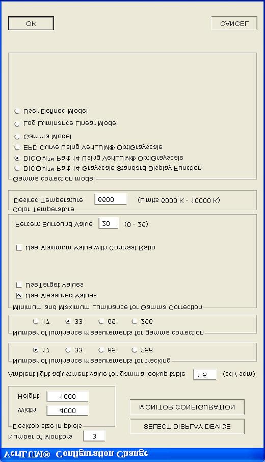
12 12

13 Figure 2A. VeriLUM Display Device Screen when using Dual Mode Pod 13

14 Figure 2B. VeriLUM Display Device Screen when using Grayscale or Older Color Pod 14

15 Figure 2C. VeriLUM Monitor Configuration Screen 15
16 2.0 Operating VeriLUM VeriLUM addresses three major operational requirements for video display quality assurance: Acceptance Testing; Calibration to a Luminance Response Model; Conformance Tracking. 2.1 Using VeriLUM for Acceptance Testing DISPLAY SMPTE PATTERN The SMPTE pattern serves a multitude of purposes. For acceptance testing it is useful to help determine whether there is video stability and general geometric and luminance fidelity. Gross distortions such as wavy lines, rectangular areas where square areas are expected, flicker, smearing and so forth should all be rectified before further testing is performed. If problems are observed which are not correctable with information supplied by the video card vendor, video display vendor, or system integrator, then a repair call is warranted. Click the CONTINUE button to return to the VeriLUM main dialog box DISPLAY VeriLUM PATTERN The VeriLUM pattern also has many uses. For acceptance testing it is used to assess geometric linearity and focus. Measure the horizontal and vertical diameters of the large circle centered in the display. Adjust the geometry to equalize these diameters. The diameters of the smaller circles in the four corners and the center can also be measured to ensure that the circles do not appear strongly elliptical. There are five objects used to determine whether the focus is adequate. Each object consists of four squares and each square has alternating white and black lines in a horizontal or vertical direction. The focus objects are in the four corners of the display and in the center. Each object should be inspected to determine whether the video display system is capable of resolving one on; one off objects. If the lines are indistinguishable, or wavy, or smeared, then the focus or astigmatism may need to be adjusted. This usually requires trained maintenance personnel with specialized equipment. Click the CONTINUE button to return to the VeriLUM main dialog box. 16
17 2.1.3 MEASURE BLACK LEVEL and MEASURE WHITE LEVEL These measurements provide an indication of the minimum and maximum luminance at which the video display system is operating. If a specification for these levels has been defined by the workstation vendor, then this is a quick way to see whether the video setup was accomplished. If there are multiple displays on a workstation and the black and white levels are quite different among the displays, then it will be very difficult to display an image on the different displays and achieve the same look-and-feel. Use these functions to ensure that the black and white levels are set at about the same value for all the displays. Many display vendors provide a digital interface and methodology (software and/or hardware) for setting the black level and the white level. If the vendor provides guidelines or if other specifications exist, use them. Otherwise, here are some rules-ofthumb and a suggested procedure Setting Black Level and White Level Using Brightness and Contrast Controls Setting the Black Level Set the room lighting for reading images from the workstation. In particular, ensure that there are no direct reflections from other objects in the room (e.g. specular reflections from lights, doorways, the desktop, keyboard, etc.). Control the ambient light to minimize diffuse reflections from the display surface. Click MEASURE BLACK LEVEL button. Using the display brightness control, turn the brightness down and then slowly raise it until a slight gray appears at the screen edges or across the whole screen. Then turn the brightness down until the gray goes away. Use this as the black level and note the measured value of the black level. In most cases the black level should be between 0.1 cd/sqm and 1.0 cd/sqm. When using a color pod, in addition to the luminance value (Y) the 1931 CIE x- and y-chromaticity values are displayed as well as the 1976 CIE u - and v -chromaticity values Setting the White Level Click MEASURE WHITE LEVEL button and adjust the display contrast control to give a desired white level. In the absence of vendor suggestions, try these: - Color Display: 85 cd/sqm (range: 70 to 120) - High Brightness Display: 140 cd/sqm (range: 120 to 180) 17
18 - P45 Grayscale Display: 250 cd/sqm (range: 200 to 300) - P104 Grayscale Display: 343 cd/sqm (range: 300 to 800) If a VeriLUM color dual mode pod (or older color pod) is being used, other values are displayed in addition to the luminance. Specifically, the CIE x and y chromaticity coordinates of the white point are displayed as well as the correlated color temperature of the white point. See Sections 3.6 and 3.7 for a discussion of these parameters. When using a color pod, in addition to the luminance value (Y) the 1931 CIE x- and y-chromaticity values are displayed as well as the 1976 CIE u - and v -chromaticity values MEASURE LUMINANCE UNIFORMITY This function measures the white level in the center and four corners of the display and indicates the percentage deviation of the corner luminance value from the center luminance value. In the absence of some other specification, the percentage deviation should not exceed plus or minus 15%. If a VeriLUM color dual mode pod is being used, then the correlated color temperature of the white patches is displayed as well MEASURE LUMINANCE A general luminance measurement function is provided. Place the VeriLUM pod where you want to measure the luminance. Measurements are made and displayed in one second intervals. Hit the Space Bar on the Keyboard to capture the luminance reading. The reading will be written into a date-time-stamped file, and stored in the folder where VeriLUM was installed. This is especially useful when VeriLUM is being run on a laptop computer and a measurement of the luminance of some external self-luminous light source is desired (for example, a film viewbox). If correction factors are being used for the display device on the system where VeriLUM is installed, then you are asked whether you want to use these correction factors for the luminance measurement of the external source. For a film viewbox you should answer NO. When using a color pod, in addition to the luminance value (Y) the 1931 CIE x- and y- chromaticity values are displayed as well as the 1976 CIE u - and v -chromaticity values. 18
19 2.2 Using VeriLUM for Calibration to a Luminance Response Model Click MEASURE LUMINANCE RESPONSE FOR GAMMA CORRECTION button and follow the onscreen instructions for placing the luminance pod and measuring the characteristic luminance response function of the video display system. When the measurements are completed a gamma correction table is written to a file in the folder to which VeriLUM was installed. This gamma correction conforms to the model specified in the Configuration Screen dialog box. Luminance measurements are written to a file named LumVals_nc.dat. The model choices are: DICOM Part 14 Grayscale Standard Display Function; DICOM Part 14 with VeriLUM OptiGrayscale (see Section 6.0); EPD Curve using VeriLUMOptiGrayscale; a Gamma Model with specified gamma value; or a User Defined Model specified by a data file. Use a gamma value of 0 to indicate that you want to calibrate and perform conformance checking to the natural gamma of the display. Note: See section 3.4 for a description of the data file format for specifying a User Defined Model. If the video board has an on-board gamma correction capability then the correction table is loaded onto the video board after the table is calculated. If the video board does not have an on-board gamma correction capability that is accessible via the operating system, then no gamma correction table is loaded. The gamma correction file is available to other software packages to use in writing pixel values to the video display (see Section 3.5). With gamma correction on-board the effect of perceptual linearization (DICOM Part 14) can be seen immediately by clicking DISPLAY SMPTE PATTERN button. You should be able to see clearly the 5% square in the 0% surround and the 95% square in the 100% surround. The perceived luminance in the other percentage squares should increase linearly as your eye moves from the 0% square around to the 100% square in a clockwise direction. Do not be confused by the optical illusion at the two 50% squares. The luminance appears to be different only because there is a 40% square to the left of one of the 50% squares and there is a 60% square to the right of the other 50% square. Press the SPACEBAR to toggle the gamma correction on and off. This is a way to visually demonstrate the effect of the gamma correction. 19
20 You can also click DISPLAY VERILUM PATTERN button. When DICOM Part 14 perceptual linearization has been applied you can see clearly the complete content of this pattern. There are squares of increasing luminance arrayed left to right across the display. There are also smaller squares within these squares and the pixel values of these smaller squares are obtained by adding and subtracting from the pixel value of the surrounding square an amount equal to one percent of the grayscale range. Again, press the SPACEBAR to toggle the gamma correction on and off. The purpose of the VeriLUM pattern is to see whether a one percent change in driving level is visible across the whole range of pixel values in an image. You can judge visually whether the DICOM Part 14 objective has been met. That is, whether equal changes in driving level produce equal changes in perceived luminance over the whole range of driving levels. When a model other than the DICOM Part 14 Grayscale Standard Display Function is used, the features of the VeriLUM and SMPTE patterns that are visualized are model dependent. If the perceptual linearization effect is not as strong visually as you expected it to be or is too strong (as judged by the visibility of the 5% square in the 0% surround of the SMPTE pattern), then click on the CHANGE CONFIGURATION button and enter a different value for the Ambient Light Adjustment Value. The default value is 1.5 cd/sqm. Increase this value if the workstation is located in a room with brighter ambient light (adjustment values as high as 5.0 cd/sqm are sometimes needed). Decrease this value if the workstation is located in a room with very low ambient light. Calibration must be performed after a change is made in the Ambient Light Adjustment Value. Click DISPLAY USER PATTERNS button to see the effect of the gamma correction on your favorite bitmap patterns. Use the SPACEBAR to toggle on and off the gamma correction lookup table. You can also display DICOM files by selecting the file type as DCM. In VeriLUM, click ENABLE GAMMA CORRECTION button to have the gamma correction table loaded then and at system startup and when each user logs onto the system. Click DISABLE GAMMA CORRECTION button to have a linear ramp loaded into the gamma correction table then and at system startup. This means that the natural gamma of the display will be operable instead of a luminance response model gamma correction. 20
21 2.3 Using VeriLUM for Conformance Tracking Click MEASURE LUMINANCE RESPONSE FOR TRACKING button and follow the on-screen instructions to perform luminance measurements and compute and display the VeriLUM Display Index, Effective Ambient Offset, White Level, and Black Level of the video display. If the VeriLUM color dual mode pod is being used, then the Correlated Color Temperature is displayed and the luminance and chromaticity values for the Red, Green, and Blue primaries are displayed. (See Figure 3B.) In addition, for color displays, you are given an opportunity to determine how well your system matches the 24 targets on the Gretag MacBeth ColorChecker chart. The comparison is done for 6500 K color temperature and a gamma model with gamma of 2.2. If a DICOM Part 14 model or some other luminance response model is used then the color match will not be as good. The 24 color target pattern may be displayed by clicking on DISPLAY USER PATTERNS and choosing the file Gretag_6500K.BMP. A display window presents the current and prior values of these parameters (See Figure 3A). Click PRINT button to print the results on the default Windows printer. Click HISTORY PLOT button to display all of the tracking results since the last calibration. An example is shown in Figure 3D. Click JND PLOT button to display a graph of the JNDs per luminance interval calculated from the tracking luminance measurements (See Figure 3C). A judgment is made as to how well the individual values of the JNDs per luminance interval correlate with the expected JNDs per luminance interval. A rating of Excellent, Good, Fair, or Poor is assigned. Click OK button to return to the VeriLUM main dialog box. 21

22 FIGURE 3A. Tracking Measurement History Report 22

23 Figure 3B. Tracking Luminance Response Report 23

24 Figure 3C. JND Conformance Test Results Plot 24

25 Figure 3D. Tracking History Plot 25
26 The VeriLUM Display Index and the Effective Ambient Light parameter have the following interpretations: The Display Index is between 01 and 10. The closer the Display Index is to 01 the closer the video display system is to matching the luminance model specified in the Configuration Screen. The Effective Ambient Light indicates the offset that gave the best estimate of the Display Index. In all cases the Display Index, Effective Ambient Light, White Level, and Black Level are tracked over time and significant change in any one of these parameters serves as a warning flag that something has changed in the video display system and investigation is warranted. For example, if the Display Index varies by 02 or more index points over time then some significant change has occurred. Of course the cause may be simply that some user has altered the brightness or contrast settings for the display. Before calling for repair of the display a new calibration should be performed, including setting the black level and the white level, and the SMPTE and VeriLUM patterns should be displayed and visually inspected. 2.4 Adjusting Color Temperature If a VeriLUM color dual mode pod is used, then color adjustments can be made to achieve a desired color temperature. In the Configuration Screen a Desired Color Temperature can be specified. The default value is 6500 K. This value provides good color reproduction capabilities. See Section 3.7 for a discussion of color temperature and some standard settings. Click ADJUST COLOR TEMPERATURE and follow the measurement instructions. When the measurements are completed, relative gain adjustments for red, green, and blue are calculated and downloaded to the video card downloadable gamma ramps. These gain adjustments are used to achieve the desired color temperature. The colors achievable by the video card are plotted as shown in Figure 4 and Figure 5. 26

27 FIGURE 4. VeriLUM 1931 CIE Chromaticity Diagram 27

28 FIGURE 5. VeriLUM 1976 CIE Chromaticity Diagram 28
29 To turn off this adjustment click RESET COLOR TEMPERATURE. An example of this color adjustment scenario is given in Section Plotting Results Click PLOT RESULTS and select one of the plot options as in Figure 6. Examples of these plots are shown in Figure 7, Figure 8, and Figure 9. 29

30 FIGURE 6. Select Plot Screen 30
31 FIGURE 7. Gamma Correction Table Plot 31

32 FIGURE 8. Calibration Luminance Response Plot 32
33 FIGURE 9. Tracking Luminance Response Plot 33
34 3 Technical Notes 3.1 White Level and Black Level Settings When the MEASURE WHITE LEVEL button is clicked, the highest driving level is used for the center square. The driving level used for the surround is experimentally determined by taking measurements until the driving level is found that gives a luminance value equal to a desired percentage of the maximum luminance. The maximum luminance is the value with a surround also at the highest driving level. The desired percentage is specified in the configuration screen. When the MEASURE BLACK LEVEL button is clicked, a luminance measurement is made in a square having a zero driving level and a surround with a driving level that gives a luminance that is equal to a desired percentage of the maximum luminance. The maximum luminance is the value with a surround also at the highest driving level. The desired percentage is specified in the configuration screen. It is important to note that the black level in VeriLUM includes veiling glare from the surround (unless 0 has been specified as the desired percent surround). However, using a VeriLUM pod pressed on the display faceplate occludes the majority of the diffuse ambient light and, therefore, the black level in VeriLUM does not include the effect of ambient light. 3.2 Luminance Measuring Device Specifications The VeriLUM Grayscale and VeriLUM Color Dual Mode pods are auto-detected. The USB pod is a low power class device. The VeriLUM photometers are manufactured and calibrated by Sequel Imaging, Inc., Londonderry, NH, and are quality control checked by IMAGE Smiths, Inc. Calibration: Traceable to a National Institute of Standards and Technology (NIST) source. Accuracy: VeriLUM Color Dual Mode Pod: Luminance +/- 2%; Chroma: +/ VeriLUM Grayscale Pod: Luminance +/- 4% Repeatability: VeriLUM Color Dual Mode Pod: Luminance +/- 1%; Chroma +/ VeriLUM Grayscale Pod: Luminance +/- 0.5% Luminance Range: VeriLUM Color Dual Mode Pod: cd/m^2 VeriLUM Grayscale Pod: cd/m^2 34
35 3.3 Number of Luminance Measurements The CHANGE CONFIGURATION dialog box in VeriLUM permits specification of the number of luminance measurements for each of tracking and gamma correction. The choices are 17, 33, 65, and 256. Cubic spline interpolation is used to produce values for the other driving levels when necessary. 3.4 User Defined Luminance Response Model Data File Format The User Defined Model data file consists of an ASCII text file with the number N of data points indicated on line 1. The next N lines contain X and Y data values separated by a comma. The X and Y values are normalized and both are between 0.0 and 1.0. Two sample files are included to illustrate the format. The file GAMMA_195.MOD contains 65 data points representing a normalized model for the luminance response Y = X**1.95. The X value ranges from 0.0 to 1.0 in increments of 1/64. The Y values are computed at the 65 X values and range from 0.0 to 1.0. The model is used by multiplying Y by the difference between the maximum and minimum luminance measurements and then adding the minimum luminance level. The file EXPONENTIAL_250.MOD contains 65 data points representing a normalized model for luminance response given by Y = (exp(2.5x) 1.0) / (exp(2.5) 1.0). 3.5 Registry Entries and Downloadable Gamma Ramps When VeruLUM is installed two entries are written to the registry in HKEY_LOCAL_MACHINE\SOFTWARE\VeriLUM. The first entry is a key named InstallDirectory and the value of this key is a null-terminated string containing the fully qualified path name of the folder into which VeriLUM was installed. Other applications can use this InstallDirectory to determine where the file called GCTn.dat is located (where n = 0, 1,, 9 denote displays on the desktop). The second registry entry is a key named LoadInd (an abbreviation for load indicator) and the value of this key is a two character null terminated string. Each of these two characters can contain the letter N or the letter Y. The right-most character indicates whether the video card supports downloadable gamma ramps. The left-most character indicates whether the user of VeriLUM has said to use a gamma correction or not. 35
36 If the LoadInd key has the value YY then a downloadable gamma ramp has been written to the video board and will be written there whenever the system is restarted. Nothing additional needs to be done by any other application software in order to use the calibration to the desired luminance response function. If the LoadInd key has the value NY then the video board is capable of handling downloadable gamma ramps, but the user of VeriLUM has said do not use the VeriLUM calibration look-uptable. Nothing additional needs to be done by other application software. If the LoadInd key has the value NN, then the video board is not capable of handling downloadable gamma ramps and the user of VeriLUM has said do not use the VeriLUM calibration lookup table. Nothing additional needs to be done by other application software. If the LoadInd key has the value YN, then the video board is not capable of handling downloadable gamma ramps, but the user of VeriLUM wants to use the results of the calibration. Other application software can then find files named GCTn.dat in the Install Directory for VeriLUM (n = 0, 1,, 9). In this case the file contains 256 unsigned short words. This is the lookup table to be applied to the 256 driving levels of image output data. These words contain values between 0 and To obtain the output of the LUT for driving level n, divide the value of the nth word by CIE Chromaticity Coordinates In 1931 the Commission Internationale de l Eclairage (CIE) devised a methodology that permits any color that can be seen by the average human eye to be denoted by a pair <x,y> of real numbers each of which is between 0 and 1. This pair of numbers is termed the chroma of the color and the graphical representation is called the 1931 CIE Chromaticity Diagram (see Figure 10 ). In 1976 a modification of this diagram was promulgated by CIE and the chroma is specified by a pair <u,v > Color Temperature A black body radiator is an object which when heated sufficiently produces a light emission whose color is directly related to the temperature. When the temperature versus the chromaticity of the emitted color is plotted on the 1931 CIE Chromaticity Diagram, the graph is referred to as the Planckian locus or black body locus and points on the locus are referred to by their color temperatures (see annotated curve in Figure 10). Two standard values of color temperature of the white point of a video display are important for medical imaging applications. One is 9300 Kelvin with <x,y> coordinates <0.285, 0.292> and the other is 6500 Kelvin with <x,y> coordinates of <0.313, 0.329>. 36
37 Many color displays for the home or office personal computer have been set up to approximate a 9300 Kelvin white point. This white level is decidedly bluish-white. Radiologists often prefer this representation for grayscale images. The 6500 Kelvin white point is also bluish-white but is more like a daylight fluorescent light. Colors for pathology specimens often look more realistic and are more reproducible when a video display system has the white point set at 6500 Kelvin. The initial desired color temperature in the VeriLUM configuration screen is set to 6500 K. When 6500 Kelvin is used and the luminance response model is specified as Gamma 2.2, then a conformance check can be performed using the Gretag MacBeth ColorChecker 24-color target pattern. This pattern is included in the install folder of VeriLUM and can be displayed using the DISPLAY USER PATTERNS button. When a white point is a mixture of colors and has an <x,y> coordinate which does not fall on the Planckian locus, but is near it, the term correlated color temperature is used instead. This is meant to indicate that the point lies on an iso-temperature line that intersects the Planckian locus at the indicated color temperature. Unless a correction can be made to have the white point lie very near to the Planckian locus, one should be wary of relying on the correlated color temperature. Slight deviations from the locus can give annoying tints to the image content and yet the white points have the same correlated color temperature. For example, consider blood on a pathology specimen that has been photographed with a digital camera and displayed on a video display system. If the blood is red when the display has a white point of 6500 Kelvin on the locus, then a correlated color temperature of 6500 Kelvin from a white point just slightly above the locus will have a greenish tint, while a white point just slightly below the locus will impart a purplish tint. The best objective is to correct to a white point on the Planckian locus. This is what VeriLUM attempts to do in the ADJUST COLOR TEMPERATURE function. 3.8 Using VeriLUM with Multiple Color Displays on a Desktop After luminance measurements are made for the gamma correction calculation, a verification measurement is performed to ensure that the gamma correction LUTs can be correctly downloaded to the video card. If there is a problem a message is displayed to indicate that gamma correction is not valid for a particular display. The reason for this verification step is that some video cards are called dual-display cards but in fact do not have multiple gamma ramps on the video card. If this problem arises, a reasonably cost effective solution is to use two PCI video cards in the PC. Each card will drive one display and each card has a downloadable gamma ramp. Then both displays can be calibrated. 37

38 FIGURE CIE Chromaticity Diagram (Courtesy of Joe Kane Productions, Inc.) 38
39 4 Calibration Scenarios 4.1 One or More Grayscale Video Displays and Downloadable Gamma Ramp Video Card Step 1. Click CHANGE CONFIGURATION and select the luminance response model to which the calibration is to conform. Step 2. Enter a value to be used for ambient light adjustment on the configuration screen. Click OK. Step 3. Set the black level by following the procedure specified in Section Set the black level on all the displays at one time. Step 4. Set the white level to the desired luminance. Use the same target value for all the displays. Step 5. If there is some difficulty setting the same black level and the same white level on all displays, then take the maximum value of the black levels and the minimum value of the white levels and enter those values for the minimum luminance and the maximum luminance in the configuration screen under the option to use target values. Otherwise, choose the option to use the measured luminance values. Step 6. Click MEASURE LUMINANCE RESPONSE FOR CALIBRATION to perform the calibration to the luminance response model you have specified. Step 7. Click MEASURE LUMINANCE RESPONSE FOR TRACKING to record results as a baseline for tracking. 39
40 4.2 One or More Color Video Displays and Downloadable Gamma Ramp Video Card Step 1. Click CHANGE CONFIGURATION and set the desired color temperature (see Section 3.7 for suggested color temperatures); select the luminance response model to which the calibration is to conform; enter a value to be used for the Ambient Light Adjustment; click OK. Step 2. Click the RESET COLOR TEMPERATURE button. Step 3. Set the black level by following the procedure specified in Section Step 4. Set the white level to the desired luminance (but be sure that the contrast control does not exceed 90%.) Step 5. Click ADJUST COLOR TEMPERATURE. Step 6. Again, use the display contrast control to set the white level to the desired luminance. Step 7. Click MEASURE LUMINANCE RESPONSE FOR CALIBRATION to perform the calibration to the luminance response model you have specified. Step 8. Click MEASURE LUMINANCE RESPONSE FOR TRACKING to record results as a baseline for tracking.. 40
41 5.0 Creating User-Defined LCD Correction Factors VeriLUM allows for the creation of correction factors for luminance values associated with LCD flat panel displays. This is only necessary when using the VeriLUM Grayscale and VeriLUM Color pods. Correction factors are not necessary when using the VeriLUM Color Dual Mode pod. Luminance measurements are taken with both a spotmeter and a VeriLUM pod, and the resultant correction factors are applied to VeriLUM luminance readings. Once the file of VeriLUM and spotmeter readings has been created, it can be sent to IMAGE Smiths, Inc. for inclusion of the LCD flat panel model description in the VeriLUM device display menu. The process for creating the correction factors using VeriLUM 5.1 is as follows: Step 1. Step 2. Step 3. Step 4. Step 5. On the Select Display Screen of the Change Configuration Screen choose the radio button LCD NO CORRECTION FACTORS. Click OK. You will be returned to the main VeriLUM menu. Click on the GENERATE LCD CORRECTION FACTORS button. Enter the desired number of readings (either 17 or 33). Be sure to control the ambient light effect (eliminate spectral ambient reflections and minimize diffuse ambient reflections). This is because you most likely will be using a spotmeter as the comparison measurement device. Begin by using the VeriLUM pod for the first measurement. [Note: Always place the VeriLUM pod on the display with the words VeriLUM Grayscale or VeriLUM Color parallel to the top bezel and the bottom bezel of the display. This will yield consistency in measurements which is important because of the angular dependence issue in LCD displays.] When asked to enter the user measurement, take a luminance measurement with a spotmeter and type in that result. Then use the VeriLUM pod for the second measurement, and the spot meter for a second measurement. Repeat the process for the specified number of measurements. To use the resulting user-defined correction files go to Select Display Device from the Change Configuration Screen and choose USER CORRECTION FACTORS. You can send us the generated file and we will add the make and model of the flat panel to our menu. The file can be found in the VeriLUM folder in Program Files. It is named UserCorrectionFactors.dat. 41
42 6.0 Using VeriLUM OptiGrayscale Characteristic Curve Files Some displays have been measured using VeriLUM OptiGrayscale and a special file has been generated and is available to aid in faster and more accurate calibration. Some of these files are available on the IMAGE Smiths, Inc. website and others are distributed by the display vendor. The files are named VeriLUM_OptiGrayscale_CharCurve_nnn.ZIP. In this filename nnn indicates a numerical designation to distinguish one auxiliary file from another. It is important that a file be used only if your display matches the display for which this file was produced. When the ZIP file is unzipped two files are created: VeriLUM_OptiGrayscale.TXT and VeriLUM_OptiGrayscale.DAT. The text file describes the display with which this file is associated. Copy these two files into the VeriLUM install folder. When you run VeriLUM V5.1 you can specify that this file is to be used to aid in the gamma correction process. On the Configuration Screen choose the option to DICOM Part 14 Using VeriLUM OptiGrayscale. When you click the button MEASURE LUMINANCE RESPONSE FOR GAMMA CORRECTION it will only take about 15 seconds to perform the calibration measurements. The number of distinct luminance values will be reported back as well as the Mean JNDs per Luminance Interval and the standard error of this mean value (i.e. the root mean squared deviation from the mean divided by the mean). You can perform Conformance Checking as usual by clicking on the MEASURE LUMINANCE RESPONSE FOR TRACKING button. 42
VeriLUM 5.2. Video Display Calibration And Conformance Tracking. IMAGE Smiths, Inc. P.O. Box 30928, Bethesda, MD USA
 VeriLUM 5.2 Video Display Calibration And Conformance Tracking IMAGE Smiths, Inc. P.O. Box 30928, Bethesda, MD 20824 USA Voice: 240-395-1600 Fax: 240-395-1601 Web: www.image-smiths.com Technical Support
ivw-ud322 / ivw-ud322f
 ivw-ud322 / ivw-ud322f Video Wall Controller Supports 2 x 2, 2 x 1, 3 x 1, 1 x 3, 4 x 1 & 1 x 4 Video Wall Array User Manual Rev. 1.01 i Notice Thank you for choosing inds products! This user manual provides
Calibrating and Profiling Your Monitor
 Calibrating and Profiling Your Monitor For this module, you will need: Eye-One measurement device Counterweight (used for LCD screens only) New, modern displays are better First, you need to use a good
3/2/2016. Medical Display Performance and Evaluation. Objectives. Outline
 Medical Display Performance and Evaluation Mike Silosky, MS University of Colorado, School of Medicine Dept. of Radiology 1 Objectives Review display function, QA metrics, procedures, and guidance provided
Monitor QA Management i model
 Monitor QA Management i model 1/10 Monitor QA Management i model Table of Contents 1. Preface ------------------------------------------------------------------------------------------------------- 3 2.
Achieve Accurate Critical Display Performance With Professional and Consumer Level Displays
 Achieve Accurate Critical Display Performance With Professional and Consumer Level Displays Display Accuracy to Industry Standards Reference quality monitors are able to very accurately reproduce video,
Table of content. Table of content Introduction Concepts Hardware setup...4
 Table of content Table of content... 1 Introduction... 2 1. Concepts...3 2. Hardware setup...4 2.1. ArtNet, Nodes and Switches...4 2.2. e:cue butlers...5 2.3. Computer...5 3. Installation...6 4. LED Mapper
MediCal Pro. Installation & User Manual
 MediCal Pro Installation & User Manual B4100132-02 July 2004 www.barco.com Contents Contents 3 Introduction 10 About this manual 10 About MediCal Pro 10 About QA tasks 11 The main window at start-up 12
Display Quality Assurance: Considerations When Establishing a Display QA Program. Mike Silosky, M.S. 8/3/2017
 Display Quality Assurance: Considerations When Establishing a Display QA Program Mike Silosky, M.S. 8/3/2017 Objectives and Outline Why, Who, What, When, Where? Discuss the resources that may be needed
ivw-fd122 Video Wall Controller MODEL: ivw-fd122 Video Wall Controller Supports 2 x 2 Video Wall Array User Manual Page i Rev. 1.
 MODEL: ivw-fd122 Video Wall Controller Supports 2 x 2 Video Wall Array User Manual Rev. 1.01 Page i Copyright COPYRIGHT NOTICE The information in this document is subject to change without prior notice
SXGA096 DESIGN REFERENCE BOARD
 SXGA096 DESIGN REFERENCE BOARD For Use with all emagin SXGA096 OLED Microdisplays USER S MANUAL VERSION 1.0 TABLE OF CONTENTS D01-501152-01 SXGA096 Design Reference Board User s Manual i 1. INTRODUCTION...
SpectraView Profiler 4.0
 Content 1. Preface... 6 2. Installation and licensing... 8 2.1. Minimum system requirements...8 2.2. Installation...10 2.3. Product registration and licensing...12 3. Quick start... 17 3.1 The user interface...17
Remote Director and NEC LCD3090WQXi on GRACoL Coated #1
 Off-Press Proof Application Data Sheet Remote Director and NEC LCD3090WQXi on GRACoL Coated #1 The IDEAlliance Print Properties Working Group has established a certification process for off-press proofs
MaxView Cinema Kit Quick Install Guide
 SYSTEM SETUP The MaxView will work at any of the following display settings: INSTALLATION MaxView Cinema Kit Quick Install Guide Step 1 - Turn off your computer. Disconnect your monitor s VGA cable from
The Extron MGP 464 is a powerful, highly effective tool for advanced A/V communications and presentations. It has the
 MGP 464: How to Get the Most from the MGP 464 for Successful Presentations The Extron MGP 464 is a powerful, highly effective tool for advanced A/V communications and presentations. It has the ability
ivw-fd133 Video Wall Controller MODEL: ivw-fd133 Video Wall Controller Supports 3 x 3 and 2 x 2 Video Wall Array User Manual Page i Rev. 1.
 MODEL: ivw-fd133 Video Wall Controller Supports 3 x 3 and 2 x 2 Video Wall Array User Manual Rev. 1.01 Page i Copyright COPYRIGHT NOTICE The information in this document is subject to change without prior
NEC MultiSync PA Series with SpectraView II
 Professional Desktop NEC MultiSync PA Series with Color calibration solution ideal for color-critical applications Thoughtfully designed and individually factory calibrated to deliver reliable, accurate
TechNote: MuraTool CA: 1 2/9/00. Figure 1: High contrast fringe ring mura on a microdisplay
 Mura: The Japanese word for blemish has been widely adopted by the display industry to describe almost all irregular luminosity variation defects in liquid crystal displays. Mura defects are caused by
CIE CIE
 U S E R M A N U A L Table of Contents Welcome to ColorFacts... 4 Installing ColorFacts... 5 Checking for ColorFacts Updates... 5 ColorFacts Registration... 6 ColorFacts Dongle... 6 Uninstalling ColorFacts...
TL-2900 AMMONIA & NITRATE ANALYZER DUAL CHANNEL
 TL-2900 AMMONIA & NITRATE ANALYZER DUAL CHANNEL DATA ACQUISITION SYSTEM V.15.4 INSTRUCTION MANUAL Timberline Instruments, LLC 1880 S. Flatiron Ct., Unit I Boulder, Colorado 80301 Ph: (303) 440-8779 Fx:
Before attempting to connect or operate this product, please read these instructions carefully and save this manual for future use.
 Operating Instructions Additional Business Intelligence Kit Model No. WJ-NVF20 WJ-NVF20E Before attempting to connect or operate this product, please read these instructions carefully and save this manual
White Paper. Uniform Luminance Technology. What s inside? What is non-uniformity and noise in LCDs? Why is it a problem? How is it solved?
 White Paper Uniform Luminance Technology What s inside? What is non-uniformity and noise in LCDs? Why is it a problem? How is it solved? Tom Kimpe Manager Technology & Innovation Group Barco Medical Imaging
Manual Version Ver 1.0
 The BG-3 & The BG-7 Multiple Test Pattern Generator with Field Programmable ID Option Manual Version Ver 1.0 BURST ELECTRONICS INC CORRALES, NM 87048 USA (505) 898-1455 VOICE (505) 890-8926 Tech Support
INSTALATION PROCEDURE
 INSTALLATION PROCEDURE Overview The most difficult part of an installation is in knowing where to start and the most important part is starting in the proper start. There are a few very important items
LCD Colour Analyser, PM 5639/06, handheld LCD Colour Analyser, PM 5639/26, industrial LCD Colour Sensor, PM 5639/94
 LCD Colour Analyser, PM 5639/06, handheld LCD Colour Analyser, PM 5639/26, industrial LCD Colour Sensor, PM 5639/94 Colour balance alignment of LCD/EL displays Optical system for spot measurements High
Yellow Frog. Manual Version 1.1
 Yellow Frog Manual Version 1.1 1 YellowFrog Contents PC Requirements...... 2 YellowFrog Power Meter Measurement.... 3 YellowFrog PC Software..... 3 Main Screen....... 4 Input Overload....... 5 Battery
Setup Guide. CalMAN Client for SCRATCH. Rev. 1.1
 Setup Guide CalMAN Client for SCRATCH Rev. 1.1 Introduction CalMAN Required Software Version: CalMAN Display Calibration Software interfaces directly with ASSIMILATE SCRATCH software through the CalMAN
NEC MultiSync PA243W. Wide Gamut color critical accurate desktop display
 NEC MultiSync PA243W Wide Gamut color critical accurate desktop display Trusted color accuracy The 24 MultiSync PA243W delivers in applications where precise color is essential. The wide-gamut W-LED backlight
Table of Contents. 2 Select camera-lens configuration Select camera and lens type Listbox: Select source image... 8
 Table of Contents 1 Starting the program 3 1.1 Installation of the program.......................... 3 1.2 Starting the program.............................. 3 1.3 Control button: Load source image......................
Pablo II. The Picasso IV video-encoder. Manual. 18 August Copyright c 1997 Village Tronic Marketing GmbH Mühlenstraße Sarstedt Germany
 Pablo II The Picasso IV video-encoder Manual 18 August 1997 Copyright c 1997 Village Tronic Marketing GmbH Mühlenstraße 2 31157 Sarstedt Germany Technical Hotline: Tel. +49 (0)5066 / 7013-10 FAX: Tel.
LG Electronics Monitor Proofing System with LG W2420R Display and Adobe Acrobat 8 Professional for GRACoL Coated #1
 Off-Press Proof Application Data Sheet LG Electronics Monitor Proofing System with LG W2420R Display and Adobe Acrobat 8 Professional for GRACoL Coated #1 The IDEAlliance Print Properties Working Group
Operating Instructions
 Operating Instructions HAEFELY TEST AG KIT Measurement Software Version 1.0 KIT / En Date Version Responsable Changes / Reasons February 2015 1.0 Initial version WARNING Introduction i Before operating
DCI Memorandum Regarding Direct View Displays
 1. Introduction DCI Memorandum Regarding Direct View Displays Approved 27 June 2018 Digital Cinema Initiatives, LLC, Member Representatives Committee Direct view displays provide the potential for an improved
IHE. Display Consistency Test Plan for Image Displays HIMMS and RSNA. Integrating the Healthcare Enterprise
 HIMMS and RSNA IHE Integrating the Healthcare Enterprise Display Consistency Test Plan for Displays 2001-05-01 Marco Eichelberg 1, Klaus Kleber 2, Jörg Riesmeier 1, Adapted for IHE Year 3 by David Maffitt
KRAMER ELECTRONICS LTD. USER MANUAL
 KRAMER ELECTRONICS LTD. USER MANUAL MODEL: Projection Curved Screen Blend Guide How to blend projection images on a curved screen using the Warp Generator version K-1.4 Introduction The guide describes
Quadro Plex D2. Mosaic Mode for windows XP Reference Guide
 Quadro Plex D2 Mosaic Mode for windows XP Reference Guide PNY Technologies, Inc. 299 Webro Rd. Parsippany, NJ 07054-0218 Tel: 408.567.5500 Fax: 408.855.0680 Features and specifications subject to change
Ultra 4K Tool Box. Version Release Note
 Ultra 4K Tool Box Version 2.1.43.0 Release Note This document summarises the enhancements introduced in Version 2.1 of the software for the Omnitek Ultra 4K Tool Box and related products. It also details
ICAC User Manual. ICAC - ( Intelligent Connection for Alignment & Calibration ) Setup Calibration Measurement USO RESTRITO. Version 14.2.
 Setup Calibration Measurement USO RESTRITO. Version 14.2.") ICAC User Manual ICAC - ( Intelligent Connection for Alignment & Calibration ) Setup Calibration Measurement Version 14.2.1 INDEX 1- Introduction ----------------------------------- 3 2- Structure -------------------------------------
ICAC User Manual ICAC - ( Intelligent Connection for Alignment & Calibration ) Setup Calibration Measurement Version 14.2.1 INDEX 1- Introduction ----------------------------------- 3 2- Structure -------------------------------------
Display Quality Assurance: Recommendations from AAPM TG270 for Tests, Tools, Patterns, and Performance Criteria
 Display Quality Assurance: Recommendations from AAPM TG270 for Tests, Tools, Patterns, and Performance Criteria Nicholas B. Bevins, Ph.D. TG270 Co-chair Display Check 2 1 TG270 Goals Provide an update
Display Quality Assurance: Recommendations from AAPM TG270 for Tests, Tools, Patterns, and Performance Criteria
 Display Quality Assurance: Recommendations from AAPM TG270 for Tests, Tools, Patterns, and Performance Criteria Nicholas B. Bevins, Ph.D. TG270 Co-chair Display Check 2 TG270 Goals Provide an update to
PYROPTIX TM IMAGE PROCESSING SOFTWARE
 Innovative Technologies for Maximum Efficiency PYROPTIX TM IMAGE PROCESSING SOFTWARE V1.0 SOFTWARE GUIDE 2017 Enertechnix Inc. PyrOptix Image Processing Software v1.0 Section Index 1. Software Overview...
User s Guide. Version
 User s Guide Version 1.3.40 2 NEC MULTIPROFILER - USER S GUIDE Software Updates Occasionally updates and enhancements to the MultiProfiler software will be made available. Visit the MultiProfiler section
Setup Guide. EIZO Monitors. Rev. 1.4
 Setup Guide EIZO Monitors Rev. 1.4 Introduction CalMAN Display Calibration Software can automatically create optimized calibration 1D or 3D LUTs for EIZO monitors equipped with a self-calibration sensor.
D-Lab & D-Lab Control Plan. Measure. Analyse. User Manual
 D-Lab & D-Lab Control Plan. Measure. Analyse User Manual Valid for D-Lab Versions 2.0 and 2.1 September 2011 Contents Contents 1 Initial Steps... 6 1.1 Scope of Supply... 6 1.1.1 Optional Upgrades... 6
Field Test 2. Installation and operation manual OPDAQ Installation and operation manual
 Field Test 2 Installation and operation manual OPDAQ 17.08.25 Installation and operation manual January 2016 How to get copies of OpDAQ technical publications: 53, St-Germain Ouest Rimouski, Québec Canada
Selected Problems of Display and Projection Color Measurement
 Application Note 27 JETI Technische Instrumente GmbH Tatzendpromenade 2 D - 07745 Jena Germany Tel. : +49 3641 225 680 Fax : +49 3641 225 681 e-mail : sales@jeti.com Internet : www.jeti.com Selected Problems
DVB-T USB SET-TOP BOX
 DVB-T USB SET-TOP BOX User Manual Version: 1.0 (February 2005) TRANSYSTEM INC. No.1-2 Li-Hsin Rd.I Science-Based Industrial Park, Hsinchu, Taiwan Tel:+886-3-5780393 Fax:+886-3-5784111 e-mail: sales@transystem.com.tw
ELSA WINNER Series M a n u a l
 Manual Series 2002 Neue ELSA GmbH, Aachen (Germany) While the information in this manual has been compiled with great care, it may not be deemed an assurance of product characteristics. Neue ELSA GmbH
DATA PROJECTOR XJ-S30/XJ-S35
 E DATA PROJECTOR XJ-S30/XJ-S35 User s Guide Be sure to read the precautions in the separate User s Guide (Basic Operation). For details about setting up the projector and lamp replacement, see the User
Colour Matching Technology
 Colour Matching Technology For BVM-L Master Monitors www.sonybiz.net/monitors Colour Matching Technology BVM-L420/BVM-L230 LCD Master Monitors LCD Displays have come a long way from when they were first
LaCie 321 LCD Monitor
 SWOP Application Data Sheet Remote Director Monitor Proofing System using the LaCie 321 LCD Monitor The SWOP Review Committee has approved the use of off-press proofs as input material to publications.
Common assumptions in color characterization of projectors
 Common assumptions in color characterization of projectors Arne Magnus Bakke 1, Jean-Baptiste Thomas 12, and Jérémie Gerhardt 3 1 Gjøvik university College, The Norwegian color research laboratory, Gjøvik,
DVB-T Box, USB Monheim/Germany Tel. +49 (0)9091/ Fax +49 (0)9091/ Hama GmbH & Co KG.
9091/ Fax +49 (0)9091/ Hama GmbH & Co KG.") www.hama.de Hama GmbH & Co KG Postfach 80 86651 Monheim/Germany Tel. +49 (0)9091/502-0 Fax +49 (0)9091/502-274 hama@hama.de www.hama.de 00062776-01.05 DVB-T Box, USB 2.0 00062776 L TV USB receiver User
www.hama.de Hama GmbH & Co KG Postfach 80 86651 Monheim/Germany Tel. +49 (0)9091/502-0 Fax +49 (0)9091/502-274 hama@hama.de www.hama.de 00062776-01.05 DVB-T Box, USB 2.0 00062776 L TV USB receiver User
NEC MultiSync PA322UHD-2. Wide Gamut 4K UHD resolution, LED-backlit color accurate desktop display
 NEC MultiSync PA322UHD-2 Wide Gamut 4K UHD resolution, LED-backlit color accurate desktop display Crisp 4K ultra high definition (UHD) resolution and incredible, predictable color accuracy. The 32 MultiSync
AC335A. VGA-Video Ultimate Plus BLACK BOX Back Panel View. Remote Control. Side View MOUSE DC IN OVERLAY
 AC335A BLACK BOX 724-746-5500 VGA-Video Ultimate Plus Position OVERLAY MIX POWER FREEZE ZOOM NTSC/PAL SIZE GENLOCK POWER DC IN MOUSE MIC IN AUDIO OUT VGA IN/OUT (MAC) Remote Control Back Panel View RGB
Company Software Manual version Issued Date Sony Corporation Projector Calibration Pro Version 0.04 Mar 3rd, 2017
 1 A. Equipment Required B. Corresponding projectors / Functions C. Preparation D. Functions E. Note 1. Equipment Required - Software: Projector Calibration Pro - Sony Projector with LAN port
Projector Management Application Version 7.00 Instruction Guide
 Projector Management Application Version 7.00 Instruction Guide Contents 1 INTRODUCTION... 4 1.1 OUTLINE... 4 1.2 SYSTEM... 4 2 INSTALLATION... 5 2.1 SYSTEM REQUIREMENTS... 5 2.2 PROJECTOR MANAGEMENT APPLICATION
7thSense Design Delta Media Server
 7thSense Design Delta Media Server Channel Alignment Guide: Warping and Blending Original by Andy B Adapted by Helen W (November 2015) 1 Trademark Information Delta, Delta Media Server, Delta Nano, Delta
Principles of LCD monitor colors
 56 Principles of LCD monitor colors Close up cross section For Color Monitors Enlarged view of LCD panel screen Ordinary computer monitors (including notebook screens) are systems incorporating transmissive
CLIPSTER. 3D LUT File Generation with the Kodak Display Manager. Supplement
 Supplement: CLIPSTER 3D LUT File Generation with the Kodak Display Manager (Version 1.0) CLIPSTER 3D LUT File Generation with the Kodak Display Manager Supplement Supplement for the CLIPSTER Documentation:
LedSet User s Manual V Official website: 1 /
 LedSet User s Manual V2.6.1 1 / 42 20171123 Contents 1. Interface... 3 1.1. Option Menu... 4 1.1.1. Screen Configuration... 4 1.1.1.1. Instruction to Sender/ Receiver/ Display Connection... 4 1.1.1.2.
Coronis 5MP Mammo. Online User Guide
 Coronis 5MP Mammo Online User Guide (This page intentionally left blank.) 2 Table of contents Table of contents Using the online User Guide...4 Sources of information... 4 User interface... 4 Graphic board
User s Guide. Version
 User s Guide Version 1.3.70 Software Updates Occasionally, updates and enhancements to the MultiProfiler software will be made available. Visit the MultiProfiler section of the NEC DISPLAY SOLUTIONS website
VideoMate U3 Digital Terrestrial USB 2.0 TV Box Start Up Guide
 VideoMate U3 Digital Terrestrial USB 2.0 TV Box Start Up Guide Compro Technology, Inc. www.comprousa.com Copyright 2001-2005. Compro Technology, Inc. No part of this document may be copied or reproduced
Precautions and Disclaimers What You Can Do with Geometry Manager Pro Check Your Computer System requirements...
 Operating Instructions Geometric & Setup Management Software Windows Geometry Manager Pro Ver. 4.0 Thank you for purchasing this Panasonic product. Before using this software, please read the instructions
Real-Time PCR System TC
 Detecting amplifier Real-Time PCR System TC 9443-007 - 46482062-2004 TECHNICAL PASSPORT ЛТОК 170604.00 DNA-Technology research-and-production close corporation Moscow, 2004 Contents 1. General information...
V9A01 Solution Specification V0.1
 V9A01 Solution Specification V0.1 CONTENTS V9A01 Solution Specification Section 1 Document Descriptions... 4 1.1 Version Descriptions... 4 1.2 Nomenclature of this Document... 4 Section 2 Solution Overview...
ME EN 363 ELEMENTARY INSTRUMENTATION Lab: Basic Lab Instruments and Data Acquisition
 ME EN 363 ELEMENTARY INSTRUMENTATION Lab: Basic Lab Instruments and Data Acquisition INTRODUCTION Many sensors produce continuous voltage signals. In this lab, you will learn about some common methods
TelePresence Cisco TelePresence Synch with Edge95MXP - Troubleshooting
 TelePresence Cisco TelePresence Synch with Edge95MXP - Troubleshooting THE SPECIFICATIONS AND INFORMATION REGARDING THE PRODUCTS IN THIS MANUAL ARE SUBJECT TO CHANGE WITHOUT NOTICE. ALL STATEMENTS, INFORMATION,
for the Epson Stylus Pro 4000 User s Guide
 for the Epson Stylus Pro 4000 User s Guide All rights reserved. No part of this publication may be reproduced, stored in a retrieval system, or transmitted in any form or by any means, electronic, mechanical,
Setup Guide. Klein K-10CP Colorimeter. Rev. 1.1
 Setup Guide Klein K-10CP Colorimeter Rev. 1.1 Introduction Klein K-10CP Included Parts The K-10CP (Cinema Pro) is a reference class non-contact optical colorimeter with superb accuracy, the fastest read
LCD and Plasma display technologies are promising solutions for large-format
 Chapter 4 4. LCD and Plasma Display Characterization 4. Overview LCD and Plasma display technologies are promising solutions for large-format color displays. As these devices become more popular, display
User Manual. When Colour is Critical
 When Colour is Critical Table of content 1. Preface... 6 2. Installation and licensing... 8 2.1. Minimum system requirements... 8 2.2. Installation... 10 2.3. Product registration and licensing... 12 3.
E X P E R I M E N T 1
 E X P E R I M E N T 1 Getting to Know Data Studio Produced by the Physics Staff at Collin College Copyright Collin College Physics Department. All Rights Reserved. University Physics, Exp 1: Getting to
DP Tuner 80 Remote Control Software User Manual. Version:08 Issue Date:May 10, 2018
 DP Tuner 80 Remote Control Software User Manual Version:08 Issue Date:May 10, 2018 Copyright Information Copyrights Lumens Digital Optics Inc. All rights reserved. Lumens is a registered trademark of Lumens
AEROTRAK PORTABLE AIRBORNE PARTICLE COUNTER MODEL 9110 QUICK START GUIDE
 AEROTRAK PORTABLE AIRBORNE PARTICLE COUNTER MODEL 9110 QUICK START GUIDE Thank you for purchasing a TSI AeroTrak Model 9110 Portable Airborne Particle Counter (particle counter). This guide will help you
Introduction...2. Features...2 Safety Precautions...2. Installation...4
 PE1900 Contents Introduction...2 Features...2 Safety Precautions...2 Installation...4 Unpacking the Display...4 Locations and Functions of Controls...4 Connections...5 Using Your Display...7 Turning the
111 Highland Drive Putnam, CT USA PHONE (860) FAX (860) SM32Pro SDK
 FAX (860) SM32Pro SDK") SM32Pro SDK Spectrometer Operating -Software Development Kit- USER MANUAL For USB 2.0 Multi-channel User Only Table of Contents Warranty and Liability...3 Location of the SDK source code for USB 2.0...4
SM32Pro SDK Spectrometer Operating -Software Development Kit- USER MANUAL For USB 2.0 Multi-channel User Only Table of Contents Warranty and Liability...3 Location of the SDK source code for USB 2.0...4
Understanding PQR, DMOS, and PSNR Measurements
 Understanding PQR, DMOS, and PSNR Measurements Introduction Compression systems and other video processing devices impact picture quality in various ways. Consumers quality expectations continue to rise
User Manual OVP Raman
 Version 6 User Manual OVP Raman 2006 BRUKER OPTIK GmbH, Rudolf-Plank-Straße 27, D-76275 Ettlingen, www.brukeroptics.com All rights reserved. No part of this manual may be reproduced or transmitted in any
USB Mini Spectrum Analyzer User Manual TSA Program for PC TSA4G1 TSA6G1 TSA8G1
 USB Mini Spectrum Analyzer User Manual TSA Program for PC TSA4G1 TSA6G1 TSA8G1 Triarchy Technologies Corp. Page 1 of 17 USB Mini Spectrum Analyzer User Manual Copyright Notice Copyright 2013 Triarchy Technologies,
2018 Quick Reference Guide
 2018 Quick Reference Guide Introduction This guide designed as a reference to the Sony BRAVIA Workflow, used to calibrate Sony's upper-end Android TVs including Z9D and subsequent LCD and OLED models.
Setting Up the Warp System File: Warp Theater Set-up.doc 25 MAY 04
 Setting Up the Warp System File: Warp Theater Set-up.doc 25 MAY 04 Initial Assumptions: Theater geometry has been calculated and the screens have been marked with fiducial points that represent the limits
Transmitter Interface Program
 Transmitter Interface Program Operational Manual Version 3.0.4 1 Overview The transmitter interface software allows you to adjust configuration settings of your Max solid state transmitters. The following
STB Front Panel User s Guide
 S ET-TOP BOX FRONT PANEL USER S GUIDE 1. Introduction The Set-Top Box (STB) Front Panel has the following demonstration capabilities: Pressing 1 of the 8 capacitive sensing pads lights up that pad s corresponding
PHY221 Lab 1 Discovering Motion: Introduction to Logger Pro and the Motion Detector; Motion with Constant Velocity
 PHY221 Lab 1 Discovering Motion: Introduction to Logger Pro and the Motion Detector; Motion with Constant Velocity Print Your Name Print Your Partners' Names Instructions August 31, 2016 Before lab, read
Setup Guide. Panasonic BT-4LH310. Rev. 1.1
 Setup Guide Panasonic BT-4LH310 Rev. 1.1 Introduction CalMAN Required Software Version CalMAN Display Calibration Software can automatically create an optimized 3D calibration LUT for the Panasonic 4LH310
USB Mini Spectrum Analyzer User s Guide TSA5G35
 USB Mini Spectrum Analyzer User s Guide TSA5G35 Triarchy Technologies, Corp. Page 1 of 21 USB Mini Spectrum Analyzer User s Guide Copyright Notice Copyright 2011 Triarchy Technologies, Corp. All rights
VSP 198CVS Quick Start
 VIEWSIZE THE WORLD VSP 198CVS Quick Start Max 2048 1152@60Hz/2560 1152 50Hz input/output resolution User customize output resolution 3G/HD/SD-SDI input Multiple cascade mapping for super resolution DVI
Neue ELSA GmbH Sonnenweg Aachen Germany
 2002 Neue ELSA GmbH, Aachen (Germany) While the information in this manual has been compiled with great care, it may not be deemed an assurance of product characteristics. Neue ELSA GmbH shall be liable
Setup Guide. Flanders Scientific BoxIO. Rev. 1.1
 Setup Guide Flanders Scientific BoxIO Rev. 1.1 Introduction CalMAN Required Version CalMAN takes advantage of the features of the Flanders Scientific BoxIO advanced color management device to calibrate
What is the history and background of the auto cal feature?
 What is the history and background of the auto cal feature? With the launch of our 2016 OLED products, we started receiving requests from professional content creators who were buying our OLED TVs for
Installer Guide. Follow these instructions to set up the PowerLite Pro Cinema 1080 projector and HQV video processor.
 Installer Guide Follow these instructions to set up the PowerLite Pro Cinema 1080 projector and HQV video processor. For more information, see the manuals that came with these products. Setting Up the
OptoFidelity Video Multimeter User Manual Version 2017Q1.0
 OptoFidelity Video Multimeter User Manual Version 2017Q1.0 OptoFidelity Oy sales@optofidelity.com www.optofidelity.com OptoFidelity 2017 Microsoft and Excel are either registered trademarks or trademarks
Interface Practices Subcommittee SCTE STANDARD SCTE Measurement Procedure for Noise Power Ratio
 Interface Practices Subcommittee SCTE STANDARD SCTE 119 2018 Measurement Procedure for Noise Power Ratio NOTICE The Society of Cable Telecommunications Engineers (SCTE) / International Society of Broadband
NanoGiant Oscilloscope/Function-Generator Program. Getting Started
 Getting Started Page 1 of 17 NanoGiant Oscilloscope/Function-Generator Program Getting Started This NanoGiant Oscilloscope program gives you a small impression of the capabilities of the NanoGiant multi-purpose
Video wall Precautions when moving and handling. Precaution. Please adhere to the warning signs printed on the box.
 Video wall Precaution 4-1. Precautions when moving and handling Please adhere to the warning signs printed on the box. Model: 47WV30MS 47WV30BR 47WV30BS 47WV30-BAAM 47WV30-BAAL 47WV50BR 47WV50MS 47LV35A
User s Guide. Version
 User s Guide Version 1.4.00 Software Updates Occasionally, updates and enhancements to the MultiProfiler software will be made available. Visit the MultiProfiler section of the NEC DISPLAY SOLUTIONS website
Dektak Step by Step Instructions:
 Dektak Step by Step Instructions: Before Using the Equipment SIGN IN THE LOG BOOK Part 1: Setup 1. Turn on the switch at the back of the dektak machine. Then start up the computer. 2. Place the sample
Statement SmartLCT User s Manual Welcome to use the product from Xi an NovaStar Tech Co., Ltd. (hereinafter referred to as NovaStar ). It is our great
. It is our great") LED Display Configuration Software SmartLCT User s Manual Software Version: V3.0 Rev3.0.0 NS110100239 Statement SmartLCT User s Manual Welcome to use the product from Xi an NovaStar Tech Co., Ltd. (hereinafter
LED Display Configuration Software SmartLCT User s Manual Software Version: V3.0 Rev3.0.0 NS110100239 Statement SmartLCT User s Manual Welcome to use the product from Xi an NovaStar Tech Co., Ltd. (hereinafter