Nixie Clock Kit IN-12B color LED backlit Operation Manual Nixie Clock Kit IN-12B V6.0 ( All Right Reserved 2015 )
|
|
|
- Rafe Simmons
- 5 years ago
- Views:
Transcription


1 Nixie Clock Kit IN-B color LED backlit Operation Manual Nixie Clock Kit IN-B V. ( All Right Reserved ) - -

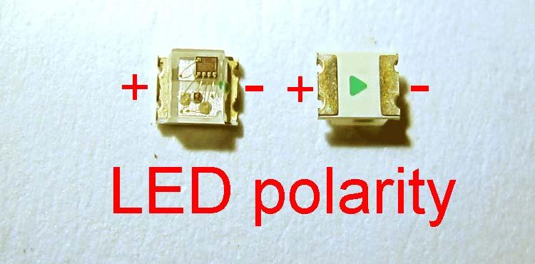
2 Operation Manual IN-B Nixie Clock Power for your Nixie Clock The clock does not include a wall adapter. You should get a universal adapter yourself, these are not very expensive. The preferred voltage is VDC, but often VDC VDC will do nicely too. The middle pin of the plug is the positive. Universal adapters often come with a set of various plugs, choose one that fits. If none them fits, you can use the dc-plug is included with the clock. If the clock does not work, you may have gotten the polarity wrong. Change the polarity and try again. Setting the Nixie Clock Turn on the clock by plugging in the wall adapter. The time will start at :: and blinks. Press and hold the Set button ( Located at the Top side, see photo ), for about - seconds until the first tube ( decimal point ) will turn on and starts blinking. Release the button. Now, with each short press of the button, you can advance the first digit. The format is hours, so the first tube only changes from -- etcetera. After the digit is set correct, press the button again for seconds, and see that the second tube will turn on. Set all the other tubes in the same way. Once you have set all digits, press and hold the button for - seconds, and the clock will resume normal operation. At first, this may seem a bit of a hassle, but after a while you will notice that it is remarkably easy to set the clock. Color LED ON/OFF Switch DC plug.mmv Setup push button - -
3 Calibrating the Nixie Clock Press and hold the set button, for about - seconds. While you hold it, you will first see that the first tube turns on its, and then the second tube will turn on its. Now release the button. There should be digits displayed now. Here you can set a new calibration value for the timing of the clock. First set this value at. After setting this value, press and hold the button for - seconds, to return to normal mode. This value will be stored inside the microcontroller. Turn off the clock, and turn it on again. Now set the clock, using a reliable time reference. Set the clock as described earlier, and wait until your time reference matches the time you have set. Now press and hold the set button for - seconds, and notice that the clock now runs synchronous with your reference, both displaying the same time. Using the standard calibration value of, the clock should run with a better accuracy than +/- seconds per day. Let the clock run for a couple of days, and note the time difference between the nixieclock and the reference clock you have used. Calculate the number of milliseconds per hour the clock runs too fast or too slow. Example: after days, the nixieclock seems seconds too fast. Divide by hours, and multiply by. That s millisecond per hour. The clock needs to run milliseconds per hour slower, so the new calibration value will be - =. Enter the new calibration value, turn off the clock, and turn it on again. Now you can set the clock, and it will be more accurate now. Repeat the procedure if need be. Setting Display Off Time Nixie tubes last very long, but possibly not forever. You may want to use this option, to turn the tubes off during the night. Press and hold the set button, for about seconds. You will first see that the first tube turns on its, and then the second tube will turn on its, and then the third tube turns on its. Now release the button. There should be values displayed now, the two middle tubes are off. These values tell you at what hour the display goes off, and at what hour it turns on again. Adjust the values to your preferences. To save the values, hold the button for - seconds, to return to normal mode. The value will be stored automatically inside the clock. If you don t want to use this option, put both hours at. (or set them at equal values). For your information, rumour tells the tubes last for hours. I have reasons to believe it will be actually longer than that, as the current at which the tubes are driven is very low and well regulated in this design. hours equals to more than years. Lifetime is defined as the time it takes for the nixies to fade to % of their initial brightness. Setting General Options In this option setup you can select fading display of the tubes, and also you can turn off the flashing neon bulbs. Press and hold the set button, for about seconds. You will first see that the first tube turns on its, and then the second tube, the third, and the fourth tube. Now release the button. There should be values displayed now, either or. A means the option is turned on, a means the option is turned off. - -
4 Adjust the values to your preferences:- The st digit sets the fading NO or OFF. The nd digit turns the flashing Neons ON or OFF. The rd option is Not Use ( Reserved ). The th option applies if you have the real time clock option installed, using a DS RTC clock chip. The th option selects / hour format, means hour format, means hour format. This option only affects the time displayed during normal operation; setting the time is always in hour format. The th option is Not Use ( Reserved ). To save the settings, hold the button for - seconds, to return to normal mode. The settings will be stored automatically inside the clock. If you have any further questions, please contact me at patnsh@hkstar.com Have fun with your new NixieClock! - -

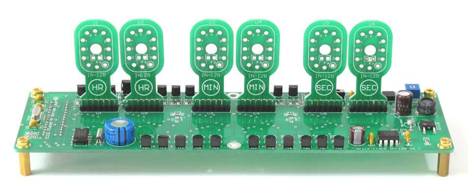
5 Assembly Instructions IN-B NOTE: Before start to soldering the clock PCB board. Please read the following instruction carefully. As this kit is equipped with PCB made Nixie Tubes adapter board to rework the IN-B pins layout to vertical insertion, some job for adapter board will be done before start soldering the clock components. The building of this Nixie Clock consist of portions :- ) The Tubes & Neon bulbs Adapter portion - making with PCB fiber boards. ) The clock portion - Clock control and tubes drive PCB. The kit come with whole set of PCB as shown below. - -
6 Tools for the adapter boards : A small size FLAT file for trimming process pcs. of pins. dual in line header pins are used for connect the Nixie Tube adapter board. Use the Flat file to trim the Neon adapter board & clock control board where with red circle marked. In order to make both parts has good insertion. -- Be careful DON'T TRIM excessive -- Make sure all the insertion parts are fitted into the main board slot as shown as photos - -
7 Assembly Instructions IN-B -- Electronic Section -- Traditional PTH (Plate Through Holes) components are used and make the soldering job and component handling simpler and easier. Also only SMT resistors and diodes are used because of no need to bend and cutoff the resistors and diodes lead before soldering more convenience and comfort. Unless you are very experienced with kit-building, it is highly recommended that you follow the steps below. First read the entire document twice, before starting. First step is to solder the resistors, capacitors, diodes,.. etc. The resistors have color code printed on them can be identified the value from the BOM list and you should not mix them up. When you are in doubt, use a multimeter and simply measure the value. The resistors are numbered in increasing order, using designators like R, R, R etc. Their values can be found in the schematic and/or component list. After you have done all the resistors., you can do the transistors. The orientation of transistors, regulator IC and diodes just follow the patterns printed on the PCB. (Don t mix them up or damaged components will result). Don t overheat the transistors, you should not spend more than a couple of seconds on each pad. Mount the electrolytic capacitors, the square hole indicates the (+) connection. Take care to mount these correctly. A reversed capacitor will certainly fail and your clock won t work. Mount all other parts on the PCB exclusive the x Nixie Tubes. Do not insert the PIC processor yet! Connect the VDC/mA (or better) adapter to the board. Test and measure if you have V on the L regulator. If you don t have V, check the polarity of your DC-adapter, you may need to reverse the +/- and check things again. Proceed if you have a clear +V. Put the screw of the potentiometer in the middle. Connect the DC adapter, but be careful not to touch any parts, after all there is a high voltage converter on the circuit board!!! Although it won t kill you immediately, it can be very uncomfortable. Check the high voltage generator; adjust it for V with a voltmeter. If you don t have V, disconnect the adapter, closely examine the entire board and check the board for shorts. Check if all parts have all their pins soldered. The next step is to insert the PIC processor. Be careful to align the pins, not to bend them as you insert the IC in its socket (the pin socket is placed on the bottom layer ). All pins first should go in about one millimeter, without any brute force needed, then you may press a bit harder until the PIC firmly sits in the socket. Please don t insert the PIC in the wrong way, there is a little notch on one end, that should match the notch on the PCB/Socket itself. Inserting it wrong will damage the PIC for % sure, your clock will never work, and you have to contact me for a replacement. - -

8 If the V is normal, you can adjust the high voltage for the nixie tubes. Later, you can always turn up the brightness adj.(hv) located at bottom side of enclosure if you find the display is too dim. A high voltage tends to show some ghosting effects before it is fixed by the employed anti-ghosting circuitry; you can adjust the brightness to suit your need. Too high voltage will shorten the life of the tubes so beware! V TP HV adjust VR Installing Neon Colon Bulbs to the PCB holder Trim the Bulbs lead to about.mm long insert to the holder and solder on the pad as shown at photo below for next installation - -
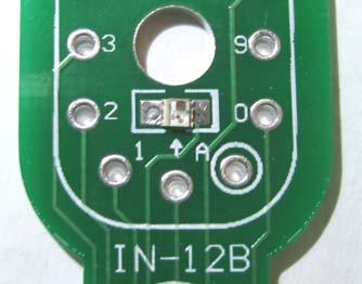
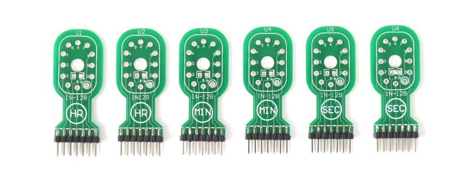
9 Installation Blacklit LED & Tubes adapter Board Header pins As shown at Photos - -


10 Mounting The Nixie Tubes & Neon Bulbs The last step is mounting the Nixie Tubes & Neon Bulbs after finished the components soldering and voltage checked normal. Start with U, the tube for the display of the seconds. After installing this tube, you can now connect the DC adapter. The U tube should display the seconds from -. If this tube does not have a display or if you are missing one or more digits, check the board again, maybe you forgot to solder one or more legs or some transistor or nixie tube wire. It is important to check this with only one tube mounted, because it makes is easier to find a fault if one exists. Mount the other five tubes and Neon colon bulbs, but do this one by one. Check the operation each and every time you add a tube. If a specific tube does not work, check the anode driver for that tube and fix the problem before proceeding further. As Shown as below photos If you got any question about the Nixie Clock just send me an at patnsh@hkstar.com ENJOY! - -
11 A B C D D C B A Title Number Revision Size A Date: -Oct- Sheet of File: D:\Nixie Clock IN-_V..ddb T MMBTA T MMBTA R K R K R K T MMBTA T MMBTA R R K R K R NL NL R K R K T MMBTA R K T MMBTA R K R K R R R K T MMBTA R K R K R K T MMBTA T MMBTA R K R K NL NL T MMBTA R K R R R K T MMBTA T MMBTA R K R K R R R R R R R R R R R R SEL SEL SEL SEL SEL SEL SEL SEL SEL SEL SEL SELSEMICOLON HV SELTUBE ANODE ANODE ANODE ANODE ANODE ANODE CI VCC DRVC SWC TC SWE IPK IC MCA R K R R K C N C P T IRFRB C U/v C u/v D BYV- L uh VDC HV P K T MMBTA T MMBTA T MMBTA T MMBTA T MMBTA T MMBTA T MMBTA T MMBTA T MMBTA T MMBTA T MMBTA T MMBTA -V adjustable REF.V SELTUBE SELTUBE SELTUBE SELTUBE SELTUBE V NIXIE TUBE U IN-B V NIXIE TUBE U IN-B V NIXIE TUBE U IN-B V NIXIE TUBE U IN-B V NIXIE TUBE U IN-B V NIXIE TUBE U IN-B D D D D D D D D D D R R HV
12 A B C D D C B A Title Number Revision Size A Date: -Sep- Sheet of File: D:\Nixie Clock IN-_V..ddb R K R K R K S XT MHZ C P C P I/O X RST BATT X VCC SCLK IC DS XT.KHZ C.F.V C N R K Vin OUT IC M D N J DC JACK C N C N C U/V VDC SEL SEL SELSEMICOLON SEL SEL SEL SEL SELTUBE SELTUBE SELTUBE SELTUBE SELTUBE SELTUBE SEL SEL SEL SEL VCC VCC VCC SEL VCC OSC/CLKIN VSS RA/AN RA/AN/VREF RA/TCKI RA/AN/SS RB/INT RB RB RB RB RB RB RB RC/TOSO/TCKI RC/TOSI/CCP RC/CCP RC/SCK/SCL RC/SDI/SDA RC/SDO RC/TX/CK RC/RX/DT MCLR RA/AN OSC/CLKOUT RA/AN VSS VDD IC PIC F
13 Bill of Material for Nixie Clock IN-B Part Type Color Code Used Designator.F.V C N D K P.K R R R R R R.u/V or.u/v C.K R R R R R R R.MHZ XT K R R R R.KHZ XT (P) C C R R R R R R R R R R R R R R R R R R R R M IC K R R (.u) C C C C u/v C C R R uh L K R R R R R R (P) C K R BYV- D DC JACK J DIODE IN D D D D D D D D D D DS IC IN-B U U U U U U (Depend on Kit Option) IRFRB T MCA IC MPSA (NPN) T T T T T T T T T T T T T T T T T T MPSA (PNP) T T T T T T PIC FA IC SW-PB S DIP SOCKET PINS (.") IC DIP SOCKET PINS IC IC NEON BULBS Metal Studs With M screws x
14
Nixie Tube Clock Type Marsden
 Assembly Instructions And User Guide Nixie Tube Clock Type Marsden Software version: RTC-1.3 PCB Revision: 16 Aug 10-1 - 1. INTRODUCTION 1.1 About the clock Nixie clock type Marsden is a compact design
Nixie Clock Type Frank 2 Z570M
 Assembly Instructions And User Guide Nixie Clock Type Frank 2 Z570M Software version: 7R PCB Revision: 11 April 09-1 - 1. INTRODUCTION 1.1 About the clock Nixie clock type Frank 2 is a compact design with
Nixie Clock Type Frank 3
 Assembly Instructions And User Guide Nixie Clock Type Frank 3 Software version: 7R PCB Version: 11 April 09-1 - 1. INTRODUCTION 1.1 About the clock Nixie clock type Frank 3 is a compact design with all
Nixie Clock Kit V1.08 Assembly and Operation
 Nixie Clock Kit V1.08 Assembly and Operation Hardware Revision 14.05.2005 Software Version 6.0 Revision 19.04.2006 This document is copyrighted. No parts of this documentation may be used commercially.
Assembly Instructions And User Guide. Nixie FunKlock. FunKlock Issue 4 (1 February 2017)
") Assembly Instructions And User Guide Nixie FunKlock - 1 - Issue Number Date REVISION HISTORY 4 1 February 2017 New diode for D2 3 27 December 2013 C7 / C8 error page 15 2 7 November 2013 Errors corrected
Assembly Instructions And User Guide Nixie FunKlock - 1 - Issue Number Date REVISION HISTORY 4 1 February 2017 New diode for D2 3 27 December 2013 C7 / C8 error page 15 2 7 November 2013 Errors corrected
Documentation VFD clock 8 a clock
 Documentation VFD clock 8 a clock This documentation is protected by our copyright. It must not be used for commercial purposes. Congratulations on your purchase of your VFD clock. To guarantee success
Bill of Materials: Super Simple Water Level Control PART NO
 Super Simple Water Level Control PART NO. 2169109 Design a simple water controller in which electrodes are required to sense high and low water levels in a tank. Whenever the water level falls below the
Mal-2 assembly guide v1.0
 Mal-2 assembly guide v.0 SONIC POTIONS Schematic and BOM The BOM can be found on Google Docs Prepare the PCB Separate the PCBs using some pliers. PCB We start with the lower PCB and assemble it beginning
Nixie Clock Type Quattro'
 Assembly Instructions And User Guide Nixie Clock Type Quattro' - 1 - Issue Number Date REVISION HISTORY 2 8 Sept 2012 Errors corrected 1 27 July 2012 New document Reason for Issue - 2 - 1.1 Nixie Quattro
ELECTRONIC GAME KIT ESSENTIAL INFORMATION. Version 2.0 BUILD YOUR OWN MEMORY & REACTIONS
 ESSENTIAL INFORMATION BUILD INSTRUCTIONS CHECKING YOUR PCB & FAULT-FINDING MECHANICAL DETAILS HOW THE KIT WORKS BUILD YOUR OWN MEMORY & REACTIONS ELECTRONIC GAME KIT Version 2.0 Build Instructions Before
SN-Class Nixie Clock Kits
 Assembly Instructions And User Guide SN-Class Nixie Clock Kits - 1 - REVISION HISTORY Issue Date Reason for Issue Number 1 20 November 2017 New document - 2 - 1. INTRODUCTION 1.1 About the How can the
DIY KIT MHZ 8-DIGIT FREQUENCY METER
 This kit is a stand-alone frequency meter capable of measuring repetitive signals up to a frequency of 50MHz. It has two frequency ranges (15 and 50 MHz) as well as two sampling rates (0.1 and 1 second).
Christmas LED Snowflake Project
 Christmas LED Snowflake Project Version 1.1 (01/12/2008) The snowflake is a follow-on from my Christmas star project from a few years ago. This year I decided to make a display using only white LEDs, shaped
Tube Cricket Build Guide
 Tube Cricket Build Guide The Tube Cricket is a small-wattage amp that puts out about 1 watt of audio power. With a 12AU7 tube-preamp and a JRC386 power amp, the Tube Cricket gives you great tone in a compact
Digital Clock. Perry Andrews. A Project By. Based on the PIC16F84A Micro controller. Revision C
 Digital Clock A Project By Perry Andrews Based on the PIC16F84A Micro controller. Revision C 23 rd January 2011 Contents Contents... 2 Introduction... 2 Design and Development... 3 Construction... 7 Conclusion...
ELECTRONIC GAME KIT TEACHING RESOURCES. Version 2.0 BUILD YOUR OWN MEMORY & REACTIONS
 TEACHING RESOURCES SCHEMES OF WORK DEVELOPING A SPECIFICATION COMPONENT FACTSHEETS HOW TO SOLDER GUIDE BUILD YOUR OWN MEMORY & REACTIONS ELECTRONIC GAME KIT Version 2.0 Index of Sheets TEACHING RESOURCES
Multi-Key v2.4 Multi-Function Amplifier Keying Interface
 Multi-Key v2.4 Multi-Function Amplifier Keying Interface ASSEMBLY & OPERATION INSTRUCTIONS INTRODUCTION The Harbach Electronics, LLC Multi-Key is a multi-function external device designed for the safe
8 PIN PIC PROGRAMMABLE BOARD (DEVELOPMENT BOARD & PROJECT BOARD)
") ESSENTIAL INFORMATION BUILD INSTRUCTIONS CHECKING YOUR PCB & FAULT-FINDING MECHANICAL DETAILS HOW THE KIT WORKS LEARN ABOUT PROGRAMMING WITH THIS 8 PIN PIC PROGRAMMABLE BOARD (DEVELOPMENT BOARD & PROJECT
ESSENTIAL INFORMATION BUILD INSTRUCTIONS CHECKING YOUR PCB & FAULT-FINDING MECHANICAL DETAILS HOW THE KIT WORKS LEARN ABOUT PROGRAMMING WITH THIS 8 PIN PIC PROGRAMMABLE BOARD (DEVELOPMENT BOARD & PROJECT
GUIDE TO ASSEMBLY OF ERICA SYNTHS DELAY MODULE
 If you are reading this, most probably, you are about to build Erica Synths DIY DELAY module. The module is 4mm deep, skiff friendly, has solid mechanical construction and doesn t require wiring. Erica
Nixie Clock Type IN-8 & NL840 Nixie'
 Assembly Instructions And User Guide Nixie Clock Type IN-8 & NL840 Nixie' - 1 - REVISION HISTORY Issue Number Date 4 15 December 2016 New diode for D2 3 30 August 2014 Typos 2 25 June 2014 Added NL840
Nixie Clock Type SixNix
 Assembly Instructions And User Guide Nixie Clock Type SixNix - 1 - Issue Number Date REVISION HISTORY Reason for Issue 6 20 March 2014 Removed WWVB Support 5 14 July 2012 New Board Issue - 19 July 12 4
Lab 7: Soldering - Traffic Light Controller ReadMeFirst
 Lab 7: Soldering - Traffic Light Controller ReadMeFirst Lab Summary The two-way traffic light controller provides you with a quick project to learn basic soldering skills. Grading for the project has been
QUIZ BUZZER KIT TEACHING RESOURCES. Version 2.0 WHO ANSWERED FIRST? FIND OUT WITH THIS
 TEACHING RESOURCES SCHEMES OF WORK DEVELOPING A SPECIFICATION COMPONENT FACTSHEETS HOW TO SOLDER GUIDE WHO ANSWERED FIRST? FIND OUT WITH THIS QUIZ BUZZER KIT Version 2.0 Index of Sheets TEACHING RESOURCES
TECHNOLOGY WILL SAVE US: THE LUMIPHONE
 TECHNOLOGY WILL SAVE US: THE LUMIPHONE This is a step-by-step guide to soldering your own Lumiphone. The equipment you should have at your station: goggles, soldering mat, soldering Iron, solder and side
VU Meter Buffer DIY Kit
 VU Meter Buffer DIY Kit Warning This document is distributed for educational purposes only. This equipment operates at potentially lethal voltages. Only trained, qualified personnel should operate, maintain,
Australian Technical Production Services
 Australian Technical Production Services Dual Rail Crowbar Copyright notice. These notes, the design, schematics and diagrams are Copyright Richard Freeman, 2015 While I am happy for the notes to be printed
Total solder points: 117 Difficulty level: beginner advanced. RGB Controller K8088 ILLUSTRATED ASSEMBLY MANUAL
 Total solder points: 117 Difficulty level: beginner 1 2 3 4 5 advanced RGB Controller K8088 Control incandescent bulbs, LEDs, common anode led strips, etc... ILLUSTRATED ASSEMBLY MANUAL H8088IP-1 Features
Lab 7: Soldering - Traffic Light Controller ReadMeFirst
 Lab 7: Soldering - Traffic Light Controller ReadMeFirst Lab Summary The two way traffic light controller provides you with a quick project to learn basic soldering skills. Grading for the project has been
XTAL Bank DDS Version 0.02 Sept Preliminary, highly likely to contain numerous errors
 XTAL Bank DDS Version 002 Sept 7 2012 Preliminary, highly likely to contain numerous errors The photo above shows the fully assembled Xtal Bank DDS with 2 DDS modules installed (The kit is normally only
Nixie Clock Type Frank 3'
 Assembly Instructions And User Guide Nixie Clock Type Frank 3' - 1 - REVISION HISTORY Issue Number Date Reason for Issue 4 16 December 2016 New diode for D2 3 12 November 2012 Improved first clock test
While the parts are already inventoried at the factory, please verify the inventory check as you go:
 Thank you for purchasing the kit for building the WJ9J DTMF controller. After building, you should read the document on operation (WJ9JDTMFControllerV5.pdf) in order to use. This is also in the link in
N3ZI Digital Dial Manual For kit with Serial LCD Rev 3.04 Aug 2012
 N3ZI Digital Dial Manual For kit with Serial LCD Rev 3.04 Aug 2012 Kit properly assembled and configured for Standard Serial LCD (LCD Not yet connected) Kit Components Item Qty Designator Part Color/Marking
Introduction 1. Green status LED, controlled by output signal ST. Sounder, controlled by output signal Q6. Push switch on input D6
 Introduction 1 Welcome to the GENIE microcontroller system! The activity kit allows you to experiment with a wide variety of inputs and outputs... so why not try reading sensors, controlling lights or
Galilean Moons. dual amplitude transmutator. DIY ASSEMBLY MANUAL v1.02
 Galilean Moons dual amplitude transmutator DIY ASSEMBLY MANUAL v1.02 Contents Contents... 2 Introduction... 3 Eurorack Kit Assembly... 4 Resistors... 4 IC Sockets... 5 Ceramic/Film Capacitors... 5 Transistors
DDS VFO CONSTRUCTION MANUAL. DDS VFO Construction Manual Issue 1.1 Page 1
 DDS VFO CONSTRUCTION MANUAL DDS VFO Construction Manual Issue 1.1 Page 1 Important Please read before starting assembly STATIC PRECAUTION The DDS VFO kit contains the following components which can be
N3ZI Digital Dial Manual For kit with Backlit LCD Rev 4.00 Jan 2013 PCB
 N3ZI Digital Dial Manual For kit with Backlit LCD Rev 4.00 Jan 2013 PCB Kit Components Item Qty Designator Part Color/Marking PCB 1 LCD Display 1 LCD 1602 Volt Regulator 1 U1 78L05, Black TO-92 Prescaler
MAKE AN RGB CONTROL KNOB.
 MAKE AN RGB CONTROL KNOB. This is a knob based colour changing controller that uses a custom programmed microcontroller to pack a lot of features into a small affordable kit. The module can drive up to
Nixie Clock Type Nixie QTC Plus
 Assembly Instructions And User Guide Nixie Clock Type Nixie QTC Plus - 1 - REVISION HISTORY Issue Date Number Draft 1 29 August 2018 New document Reason for Issue - 2 - 1. INTRODUCTION 1.1 Nixie QTC Plus
Introduction 1. Green status LED, controlled by output signal ST
 Introduction 1 Welcome to the magical world of GENIE! The project board is ideal when you want to add intelligence to other design or electronics projects. Simply wire up your inputs and outputs and away
Introduction 1. Digital inputs D6 and D7. Battery connects here (red wire to +V, black wire to 0V )
") Introduction 1 Welcome to the magical world of GENIE! The project board is ideal when you want to add intelligence to other design or electronics projects. Simply wire up your inputs and outputs and away
Introduction 1 Welcome to the magical world of GENIE! The project board is ideal when you want to add intelligence to other design or electronics projects. Simply wire up your inputs and outputs and away
Build Your Own Clone Super 8 Kit Instructions
 Build Your Own Clone Super 8 Kit Instructions Warranty: BYOC, Inc. guarantees that your kit will be complete and that all parts and components will arrive as described, functioning and free of defect.
Nixie Clock Type Nixie QTC
 Assembly Instructions And User Guide Nixie Clock Type Nixie QTC - 1 - REVISION HISTORY Issue Number Date Reason for Issue 12 10 September 2015 C6 changed to 33pF 11a 11 December 2014 C5 changed to 10pF.
VU-1 VU Meter Kit Volume Unit Meter
 VU-1 VU Meter Kit Volume Unit Meter Simplicity Counts, Detail Matters. No part of this document may be reproduced, either mechanically or electronically, posted online on the Internet, in whole or in part,
Pixie Construction Notes
 Pixie Construction Notes PCB V2a February 4 th 2015 Please note that this document is still currently under revision and we apologise for any errors or omissions. Readers should feel free to e-mail any
ASSEMBLING. the. ECEbot. Printed Circuit Board: Part Three. Due Date. The Part Three assembly steps must be completed prior to:
 ASSEMBLING the ECEbot Printed Circuit Board: Part Three Due Date The Part Three assembly steps must be completed prior to: Prepared by R.C. Maher September 2008 Copyright 2008 Department of Electrical
Assembly Instructions And User Guide. Elite Nixie. Nixie Tube Clock Elite Issue 2 (07 June 2018)
") Assembly Instructions And User Guide Elite Nixie - 1 - REVISION HISTORY Issue Number Date Reason for Issue 2 07 June 2018 Added more NL840 details 1 04 May 2018 New document - 2 - 1. INTRODUCTION Here
Assembly Instructions And User Guide Elite Nixie - 1 - REVISION HISTORY Issue Number Date Reason for Issue 2 07 June 2018 Added more NL840 details 1 04 May 2018 New document - 2 - 1. INTRODUCTION Here
Total solder points: 123 Difficulty level: beginner 1. advanced AUDIO ANALYZER K8098. audio gea Give your. . high-tech ILLUSTRATED ASSEMBLY MANUAL
 Total solder points: 123 Difficulty level: beginner 1 2 3 4 5 advanced AUDIO ANALYZER K8098 ra audio gea Give your. look high-tech ILLUSTRATED ASSEMBLY MANUAL H8098IP-1 Features & Specifications Features
COLOUR CHANGING USB LAMP KIT
 TEACHING RESOURCES SCHEMES OF WORK DEVELOPING A SPECIFICATION COMPONENT FACTSHEETS HOW TO SOLDER GUIDE SEE AMAZING LIGHTING EFFECTS WITH THIS COLOUR CHANGING USB LAMP KIT Version 2.1 Index of Sheets TEACHING
Build A Video Switcher
 Build A Video Switcher VIDEOSISTEMAS serviciotecnico@videosistemas.com www.videosistemas.com Reprinted with permission from Electronics Now Magazine September 1997 issue Copyright Gernsback Publications,
MONO AMPLIFIER KIT ESSENTIAL INFORMATION. Version 2.2 CREATE YOUR OWN SPEAKER DOCK WITH THIS
 ESSENTIAL INFORMATION BUILD INSTRUCTIONS CHECKING YOUR PCB & FAULT-FINDING MECHANICAL DETAILS HOW THE KIT WORKS CREATE YOUR OWN SPEAKER DOCK WITH THIS MONO AMPLIFIER KIT Version 2.2 Build Instructions
MAIN PCB (The small one) OPEN MAIN BOARD BAG A
 OPEN MAIN BOARD BAG A") THANKS FOR CHOOSING ONE OF OUR KITS! This manual has been written taking into account the common issues that we often find people experience in our workshops. The order in which the components are placed
THANKS FOR CHOOSING ONE OF OUR KITS! This manual has been written taking into account the common issues that we often find people experience in our workshops. The order in which the components are placed
Industrial Monitor Update Kit
 Industrial Monitor Update Kit (Bulletin Number 6157) Installation Instructions 2 Table of Contents Table of Contents Industrial Monitor Update Kit... 3 Overview... 3 Part 1 - Initial Preparation... 5 Part
Installing The PK-AM keyer and. from Jackson Harbor Press Operating: A Morse code keyer chip with pot speed control
 Installing The PK-AM keyer and from Jackson Harbor Press Operating: A Morse code keyer chip with pot speed control The PK-AM keyer is a modification for the PK-AM kit, it changes the AM transmitter to
7 SEGMENT LED DISPLAY KIT
 ESSENTIAL INFORMATION BUILD INSTRUCTIONS CHECKING YOUR PCB & FAULT-FINDING MECHANICAL DETAILS HOW THE KIT WORKS CREATE YOUR OWN SCORE BOARD WITH THIS 7 SEGMENT LED DISPLAY KIT Version 2.0 Which pages of
Main PCB (The small one)
") Thanks for choosing our kits! This manual is written taking with the problems that we usually find in our workshops in mind. Also the order is meant to make assembly as easy as possible. Some steps are
Thanks for choosing our kits! This manual is written taking with the problems that we usually find in our workshops in mind. Also the order is meant to make assembly as easy as possible. Some steps are
TKEY-K16. Touch CW automatic electronic keyer. (No moving parts no contacts) Assembly manual. Last review: March 15, 2018
 Assembly manual. Last review: March 15, 2018") TKEY-K16 Touch CW automatic electronic keyer (No moving parts no contacts) Assembly manual Last review: March 15, 2018 Commands and use manual of the K16 and Updates and news: www.ea3gcy.com Thanks for
TKEY-K16 Touch CW automatic electronic keyer (No moving parts no contacts) Assembly manual Last review: March 15, 2018 Commands and use manual of the K16 and Updates and news: www.ea3gcy.com Thanks for
Color Organ Triple Deluxe II.
 http://wwwinstructablescom/id/color-organ-triple-deluxe-ii/ Food Living Outside Play Technology Workshop Color Organ Triple Deluxe II by ledartist on January 13, 2013 Table of Contents Color Organ Triple
DEM 9ULNACK 3.4 GHz. PHEMT LNA amplifier complete kit assembly guide
 DEM 9ULNACK 3.4 GHz. PHEMT LNA amplifier complete kit assembly guide SPECIFICATIONS Noise Figure: < 0.8 db Gain: > 15 db Frequency Range: 3400-3500 MHz Input Voltage: 7-16 VDC Description: The 9ULNACK
Arduino Modular IN-14 Nixie Clock Rev2 V45 All-In-One Modular Clock Operating Instructions & Construction Manual
 Arduino Modular IN-14 Nixie Clock Rev2 V45 All-In-One Modular Clock Operating Instructions & Construction Manual NixieClockModularInstructionManualRev2V45 Contact Information If you want to get in contact
FSM User Guide Page 1 of 28
 FSM User Guide Page 1 of 28 Field Strength Meter User Guide and Kit Assembly Instructions PCB V1.1 Important: Always use or print this document in colour as there are references to the colours of components.
Arduino IN-14 Nixie Clock v42 All-In-One Clock Operating Instructions & Construction Manual
 Arduino IN-14 Nixie Clock v42 All-In-One Clock Operating Instructions & Construction Manual NixieClockIN14InstructionManualRev2V42 Contact Information If you want to get in contact with us, please email
DIY Guide - Building Franky v1.1, the SEGA Audio and Videocard for MSX
 DIY Guide - Building Franky v1.1, the SEGA Audio and Videocard for MSX 2015 FRS & MSXpró. Translation by FRS and Supersoniqs. Table of Contents Introduction... 3 Materials needed... 3 Audio volume boost...
POINTS POSITION INDICATOR PPI4
 POINTS POSITION INDICATOR PPI4 Monitors the brief positive operating voltage across points motors when they are switched Lights a corresponding led on a control panel to show the last operation of each
ADD AN AUDIO MESSAGE TO YOUR PRODUCT WITH THIS RECORD & PLAYBACK KIT
 ADD AN AUDIO MESSAGE TO YOUR PRODUCT WITH THIS RECORD & PLAYBACK KIT BUILD INSTRUCTIONS Before you start take a look at the Printed Circuit Board (PCB). The components go in the side with the writing on
Reaction Game Kit MitchElectronics 2019
 Reaction Game Kit MitchElectronics 2019 www.mitchelectronics.co.uk CONTENTS Schematic 3 How It Works 4 Materials 6 Construction 8 Important Information 9 Page 2 SCHEMATIC Page 3 SCHEMATIC EXPLANATION The
NewScope-7A Operating Manual
 2016 SIMMCONN Labs, LLC All rights reserved NewScope-7A Operating Manual Preliminary May 13, 2017 NewScope-7A Operating Manual 1 Introduction... 3 1.1 Kit compatibility... 3 2 Initial Inspection... 3 3
Advanced Design of Smart Digital Application Using PIC 16F887A Microcontroller and DS 1307 RTC
 American Journal of Embedded Systems and Applications 2018; 6(1): 30-36 http://www.sciencepublishinggroup.com/j/ajesa doi: 10.11648/j.ajesa.20180601.15 ISSN: 2376-6069 (Print); ISSN: 2376-6085 (Online)
RSH27 Nixie Tube Socket with LED
 Contents: 1. Applications of the socket 2. Solder instructions of the socket 3. Drawing of the assembled socket 4. Section drawing of the socket with IN-8 tube 5. Drawing and technical data of the tube
Building the BX24-AHT
 Building the BX24-AHT file:///f /LASER/build-it.htm (1 of 8) [03/04/2002 5:21:52 PM] file:///f /LASER/build-it.htm (2 of 8) [03/04/2002 5:21:52 PM] Tips & Tricks Use a 25W or smaller soldering iron with
Build Your Own Clone Relay Bypass Board Instructions
 Build Your Own Clone Relay Bypass Board Instructions Parts list for the Relay Bypass Board Resistors: 1-2k2/222 (Red/Red/Black/Brown/Brown) 1-10k/103 (Brown/Black/Black/Red/Brown) Capacitors: 2-100n/.1uF/104
Laboratory 8. Digital Circuits - Counter and LED Display
 Laboratory 8 Digital Circuits - Counter and Display Required Components: 2 1k resistors 1 10M resistor 3 0.1 F capacitor 1 555 timer 1 7490 decade counter 1 7447 BCD to decoder 1 MAN 6910 or LTD-482EC
Fixed Audio Output for the K2 Don Wilhelm (W3FPR) & Tom Hammond (NØSS) v August 2009
 & Tom Hammond (NØSS) v August 2009") Fixed Audio Output for the K2 Don Wilhelm (W3FPR) & Tom Hammond (NØSS) v. 2.1 06 August 2009 I have had several requests to provide a fixed audio output from the K2. After looking at the circuits that
Fixed Audio Output for the K2 Don Wilhelm (W3FPR) & Tom Hammond (NØSS) v. 2.1 06 August 2009 I have had several requests to provide a fixed audio output from the K2. After looking at the circuits that
NCV NIXIE CLOCK
 NCV3.1-16 NIXIE CLOCK Assembling manual & user's guide UG-02-16-REV-E FW-REV-02 This page intentionally left blank 1. Introduction TubeHobby congratulates you on your choice and wishes enjoyable assembling
Analog Style LED Clock
 Analog Style LED Clock Operation and Assembly Manual For use with PCB Rev 2.1 Copyright 2018 All Rights Reserved. Manual version 2.1c, for use with PCB revision 2.1, Software version 2.0.0. The electronic
Laboratory 11. Required Components: Objectives. Introduction. Digital Displays and Logic (modified from lab text by Alciatore)
") Laboratory 11 Digital Displays and Logic (modified from lab text by Alciatore) Required Components: 2x lk resistors 1x 10M resistor 3x 0.1 F capacitor 1x 555 timer 1x 7490 decade counter 1x 7447 BCD to
Laboratory 11 Digital Displays and Logic (modified from lab text by Alciatore) Required Components: 2x lk resistors 1x 10M resistor 3x 0.1 F capacitor 1x 555 timer 1x 7490 decade counter 1x 7447 BCD to
Alice EduPad Board. User s Guide Version /11/2017
 Alice EduPad Board User s Guide Version 1.02 08/11/2017 1 Table OF Contents Chapter 1. Overview... 3 1.1 Welcome... 3 1.2 Launchpad features... 4 1.3 Alice EduPad hardware features... 4 Chapter 2. Software
Mini-Yack Iambic Keyer
 Mini-Yack Iambic Keyer Assembly Instructions Mini-Yack is a "bare bones" Iambic keyer for embedding into QRP and home brew equipment. The keyer has the following features: Keying from 1-50WPM YACK memory
Bill of Materials: Magic Color PART NO
 Magic Color PART NO. 2193838 Magic color is a guessing game. With this game you can surprise your friends and leave them with amazement, how the game guesses what they have in their minds. Only two selections
LED Array Board.
 LED Array Board www.matrixtsl.com EB087 Contents About This Document 2 General Information 3 Board Layout 4 Testing This Product 5 Circuit Description 6 Circuit Diagram 7 About This Document This document
Combo Board.
 Combo Board www.matrixtsl.com EB083 Contents About This Document 2 General Information 3 Board Layout 4 Testing This Product 5 Circuit Diagram 6 Liquid Crystal Display 7 Sensors 9 Circuit Diagram 10 About
Nixie Clock Type Nixie Maestro
 Assembly Instructions and User Guide Nixie Clock Type Nixie Maestro - 1 - Issue Number Date REVISION HISTORY Reason for Issue 4 01 April 2017 New version with neons for AM / PM 3 10 December 2014 Typing
Dust Sensor using GP Y
 Dust Sensor using GP Y Dust sensors detect fine dust ( aerosol ) floating in the air. They are used to determine air quality indoor and outdoor. Limits of the GP2Y10 The GP2Y10 sensor was developed to
[ Photos ] [ Wares ] [ Library ] [ Dave's Web ] [ Matt's Web ] Wares [ SWISH ] [ Simple Search ] [ Trunk Calc ]
![[ Photos ] [ Wares ] [ Library ] [ Dave's Web ] [ Matt's Web ] Wares [ SWISH ] [ Simple Search ] [ Trunk Calc ]](/thumbs/85/91698811.jpg "[ Photos ] [ Wares ] [ Library ] [ Dave's Web ] [ Matt's Web ] Wares [ SWISH ] [ Simple Search ] [ Trunk Calc ]") [ Photos ] [ Wares ] [ Library ] [ Dave's Web ] [ Matt's Web ] Wares [ SWISH ] [ Simple Search ] [ Trunk Calc ] Realistic PRO-2006 Hardware Modifications Note Edited on January 1st, 1970, 00:00 UT. Improper
[ Photos ] [ Wares ] [ Library ] [ Dave's Web ] [ Matt's Web ] Wares [ SWISH ] [ Simple Search ] [ Trunk Calc ] Realistic PRO-2006 Hardware Modifications Note Edited on January 1st, 1970, 00:00 UT. Improper
AXE101 PICAXE-08M2 Cyberpet Kit
 AXE101 PICAXE-08M2 Cyberpet Kit The Cyberpet project uses a PICAXE-08M2 microcontroller with two LEDs as the pets eyes and a piezo sounder as a voice for the pet. The project also uses a switch so that
MOD028 GLOCKENSPIEL TECHNO-MUSIC-OLOGY
 MOD028 GLOCKENSPIEL TECHNO-MUSIC-OLOGY MOD028 - Techno-music-ology Kit Contents Motor Controller PCBs 14 220R (red red brown gold) resistors 2 330R (orange orange brown gold) resistors 16 1N4001 diodes
Step What to do Expected result What to do if test fails Component tested 1 Visual inspection. Board is accurately assembled
 Fox Delta Amateur Radio Projects & Kits AAZ-0914A 50MHZ Antenna Analyzer Testing Guide by Tony / I2TZK SWR Analyzer 4 steps for a quick test Step What to do Expected result What to do if test fails Component
DLP600M 6+1 Relay Module for Heating and Cooling Plants
 Product Sheet TH6.25 Thermostat Type DLP600M DLP600M 6+1 Relay Module for Heating and Cooling Plants The DLP 600 M is a relay module for activation of loads (namely thermal actuators or circulators) in
16 Stage Bi-Directional LED Sequencer
 16 Stage Bi-Directional LED Sequencer The bi-directional sequencer uses a 4 bit binary up/down counter (CD4516) and two "1 of 8 line decoders" (74HC138 or 74HCT138) to generate the popular "Night Rider"
DOGM GRAPHIC SERIES 132x32 DOTS
 DOGM GRAPHIC SERIES 132x32 DOTS 6.2009 flexible display content! EA DOGM132B-5 + EA LED55x31-W TECHNICAL DATA EA DOGM132W-5 + EA LED55x31-A EA DOGM132W-6 + EA LED55x31-W * HIGH-CONTRAST LCD SUPERTWIST
Bas Gialopsos Atari PureVideo Encoder Module 2600VECr5.2
 Bas Gialopsos 2014 Atari PureVideo Encoder Module 2600VECr5.2 Table of Contents Description Disclaimer Technical and Signal Identification Installation Instructions Tools Required Caution Installation
How To Build Megavolt s Small Buffered JTAG v1.2
 How To Build Megavolt s Small Buffered JTAG v1.2 Abstract A JTAG cable should be considered mandatory equipment for any serious tester. It provides a means to backup the information in the receiver and
DRAFT Microprocessors B Lab 3 Spring PIC24 Inter-Integrated Circuit (I 2 C)
") PIC24 Inter-Integrated Circuit (I 2 C) Lab Report Objectives Materials See separate report form located on the course webpage. This form should be completed during the performance of this lab. 1) To utilize
PIC24 Inter-Integrated Circuit (I 2 C) Lab Report Objectives Materials See separate report form located on the course webpage. This form should be completed during the performance of this lab. 1) To utilize
RECORD & PLAYBACK KIT
 TEACHING RESOURCES SCHEMES OF WORK DEVELOPING A SPECIFICATION COMPONENT FACTSHEETS HOW TO SOLDER GUIDE ADD AN AUDIO MESSAGE TO YOUR PRODUCT WITH THIS RECORD & PLAYBACK KIT Version 2.1 Index of Sheets TEACHING
Modellbahn Digital Peter Stärz
 Modellbahn Digital Peter Stärz Dresdener Str. 68 D-02977 Hoyerswerda +49 3571 404027 www.firma-staerz.de info@firma-staerz.de 8-fold Track Occupancy Detector for digital systems with two-wire track (e.g.
SWITCH: Microcontroller Touch-switch Design & Test (Part 2)
") SWITCH: Microcontroller Touch-switch Design & Test (Part 2) 2 nd Year Electronics Lab IMPERIAL COLLEGE LONDON v2.09 Table of Contents Equipment... 2 Aims... 2 Objectives... 2 Recommended Timetable... 2
SWITCH: Microcontroller Touch-switch Design & Test (Part 2) 2 nd Year Electronics Lab IMPERIAL COLLEGE LONDON v2.09 Table of Contents Equipment... 2 Aims... 2 Objectives... 2 Recommended Timetable... 2
DL-1A. RF dummy load - 50Ω 20W. Assembly manual. Last update: May 1, Thank you for constructing the DL-1A dummy load kit
 DL-1A RF dummy load - 50Ω 20W Assembly manual Last update: May 1, 2016 ea3gcy@gmail.com Updates and news at: www.qsl.net/ea3gcy Thank you for constructing the DL-1A dummy load kit Have fun assembling it
STROBOSCOPE LIGHT EFFECT KIT
 STROBOSCOPE LIGHT EFFECT KIT Easy to build stroboscope for general applications Flash frequency: 5 to 15 flashes per second Power supply: 110VAC Power consumption: 13W max. PCB dimensions: 50 x 75mm modifications
MACH3 LaserAce Installation Manual Revision 1. MACH3 LaserAce Installation Manual
 WWW.LASERARCADE.COM MACH3 LaserAce Installation Manual Revision 1 MACH3 LaserAce Installation Manual Table of Contents Introduction...1 Parts supplied with MACH3 FNI...1 Why the MACH3 FNI is required...2
QTI Line Follower AppKit for the Boe-Bot (#28108)
") Web Site: www.parallax.com Forums: forums.parallax.com Sales: sales@parallax.com Technical: support@parallax.com Office: (916) 624-8333 Fax: (916) 624-8003 Sales: (888) 512-1024 Tech Support: (888) 997-8267
Web Site: www.parallax.com Forums: forums.parallax.com Sales: sales@parallax.com Technical: support@parallax.com Office: (916) 624-8333 Fax: (916) 624-8003 Sales: (888) 512-1024 Tech Support: (888) 997-8267
DMC550 Technical Reference
 DMC550 Technical Reference 2002 DSP Development Systems DMC550 Technical Reference 504815-0001 Rev. B September 2002 SPECTRUM DIGITAL, INC. 12502 Exchange Drive, Suite 440 Stafford, TX. 77477 Tel: 281.494.4505