Introduction: CW SRF linac types, requirements and challenges High power RF system architecture
|
|
|
- Elizabeth Fisher
- 5 years ago
- Views:
Transcription
1 RF systems for CW SRF linacs S. Belomestnykh Cornell University Laboratory for Elementary-Particle Physics LINAC08, Victoria, Canada October 1, 2008
2 Outline L band Introduction: CW SRF linac types, requirements and challenges High power RF system architecture RF power generation options: klystron vs IOT vs solid state amplifier Specific projects, operating or under construction: JLab FEL & CEBAF ELBE ALICE Cornell ERL injector UHF band VHF band Future projects and requirements Summary ERL prototype for electron cooling and erhic at BNL SPIRAL-2 October 1, 2008 S. Belomestnykh: RF systems for CW SRF linacs 2
3 Introduction One can distinguish four types of CW SRF linacs: o Low-current high-β linacs: typically L band, low to medium RF power o o o ERLs: L or UHF band, low to medium RF power High-current high-β injectors/drivers: L or UHF band, medium to high RF power Low-β linacs: VHF band, low o medium RF power Requirements/challenges: o o o o o o o Provide stable, reliable source of RF power Maintain stable cavity field (amplitude and phase) - LLRF High efficiency of converting AC power to RF and transferring it to SRF cavities High availability of the RF system Easy maintainability Cost-effective design Compactness, especially for large installations (e.g. CEBAF) In this talk we will consider only medium and high RF power systems October 1, 2008 S. Belomestnykh: RF systems for CW SRF linacs 3
4 High/medium/low RF power RF POWER SOURCES FOR CW SRF LINACS klystrons VHF to UHF frequencies: Coaxial transmission lines, losses increase as f AVERAG GE POWER, KW HIGH POWER MEDIUM POWER VHF BAND Solid state amplifiers UHF BAND L B A N D IOTs UHF and higher: Waveguides, losses increase as ~f^3/2 as in addition to skin depth decrease one has to use smaller and smaller size waveguides LOW POWER FREQUENCY, MHZ October 1, 2008 S. Belomestnykh: RF systems for CW SRF linacs 4
5 CW SRF system architecture All CW SRF linacs use a simple architecture with one RF high power amplifier per cavity. Reasons: flexibility, available RF power sources, requirements to fiels stability, efficiency of RF system,... Drive From RFCM To RFCM 12 GeV CEBAF Upgrade Transition Reflected Coupler Dual Coupler Tuner Waveguide To RFCM Driver Driver PS Klystron Filament PS Detector Load Beam Cryomodule Mod Anode PS Ion Pump Controller Solenoid Power Key Waveguide System To RFCM & HPA Controller Instrumentation HPA 1 of 8 Power Supplies Utilities PSS DC Control AC LCW Instrumentation RF High Power HV DC (15 kv) Power 480/208/120 VAC LCW (cooling) RF Low Power HV DC October 1, 2008 S. Belomestnykh: RF systems for CW SRF linacs 5
6 How RF power spec is set? 1. Calculate beam loading 2. Add margin for regulation 3. Set requirement for RF power available at the cryomodule for each family of cavities 4. Set requirement for power available at the high power amplifier taking into account losses in the transmission line elements SPIRAL-2 25 Beam Loading or cavity loss Linac amplifier power budget mdg 03/09/08 20 Margin power +30% Amplifier and circulator power 15 Net power kw RE EG 1 RE EG 2 RE EG 3 CA1 CA2 CA3 CA4 CA5 CA6 CA7 CA8 CA9 CA10 CA11 CA12 CB1 CB2 CB3 CB4 CB5 CB6 CB7 CB8 CB9 CB10 CB11 CB12 CB13 CB14 October 1, 2008 S. Belomestnykh: RF systems for CW SRF linacs 6


7 RF power generation options Klystron RF power generation at higher frequencies is still dominated by vacuum tubes: klystrons and, with the success in broadcast applications, IOTs At lower frequencies tetrodes were traditionally used, but recent progress in solid state technology will make it the technology of choice in VHF and UHF bands, except when very high power is required. IOT Solid state October 1, 2008 S. Belomestnykh: RF systems for CW SRF linacs 7
8 RF power generation options Choice of RF power source: klystron vs. IOT Injector Klystron Electron bunches are formed by velocity modulation from the cavities translated into density modulation in the drift spaces Several bunching cavities, optional mod anode High gain (> 40 db): low power drive amplifier High efficiency in saturation, which drops rapidly at reduced power Longer, expensive device Can be designed for very high power operation Main linac IOT Density modulation directly from cathode Control grid Low gain (~22 db): high power drive amplifier (expensive) Higher efficiency, which does not drop quickly at reduced power: highly linear device Shorter, less expensive tube Output power is limited though R&D for high power tubes are under way Efficiency [% ] Normalized characteristics of output power (vertical axis) vs. drive power (horizontal axis) for klystrons (blue, saturating) and IOTs (green, not saturating). Efficiency of Klystron and IOT 80 short time operating range in 70 case of microphonic 60 detuning RF Power [kw] range normal operating r IOT Prototyp Klystron VKL7811 optimized Klystron October 1, 2008 S. Belomestnykh: RF systems for CW SRF linacs 8


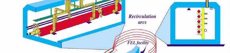

9 JLab SRF linacs CEBAF October 1, 2008 S. Belomestnykh: RF systems for CW SRF linacs 9
10 RF zone configuration 3 control racks 5 racks for klystrons: VKL6811W (CPI) or L491 (L3) Single shared HV power supply 42 systems in CEBAF 3 more in FEL FEL Injector 2 stand-alone alone 100 kw klystrons: VKL7966A (CPI) October 1, 2008 S. Belomestnykh: RF systems for CW SRF linacs 10


11 Klystron configuration 8 klystrons per zone Powered from single HV power supply Circulators, couplers, etc. 4 waveguides per penetration to tunnel After addressing initial failure modes, present average lifetime of the klystrons is 165,000 hours October 1, 2008 S. Belomestnykh: RF systems for CW SRF linacs 11

 38 db gain 4 cavity design Coaxial output")


12 JLab klystrons VLK7811W Purchased through competitive bid Order of 350 units 3 year delivery period Specifications 5 kw CW A 32.4% efficiency (min) 38 db gain 4 cavity design Coaxial output Permanent magnet focusing Potted gun Size limitations L491 Replacement from competitive bid Multi-year order Purchase in lots of 10 or 20 units 119 received VKL7966A 110 kwatts A 1497 MHz -1dB Bandwidth 14 MHz Saturated Gain 55.5 db Efficiency 51 % October 1, 2008 S. Belomestnykh: RF systems for CW SRF linacs 12

13 CEBAF 12-GeV Upgrade October 1, 2008 S. Belomestnykh: RF systems for CW SRF linacs 13


14 RF for 12-GeV Upgrade 10 new zones of RF power for Fast Sl ( <1sec) new accelerating structures: 80 new tubes, 10 HVPS Phase Stability WG network for 80 cavities Operating freq MHz Operating gradients required >17.5 MV/m Operating RF power per cavity 13 kw saturated power (rms) Amplitude (rms) EPICS IOC Slow (>1sec) correlated 0.24º Infinite un-correlated 0.5º 3.0º correlated 2.2x10⁻⁵ NA un-correlated 4.5x10⁻⁴ NA Ethernet High Voltage Power Supply Ethernet RF System Master Oscillator LLRF Controls Klystron 8 Superconducting Cavity October 1, 2008 S. Belomestnykh: RF systems for CW SRF linacs 14


15 RF layout 2007 Conceptual 2008 Design Detail Aisle view Centerline view October 1, 2008 S. Belomestnykh: RF systems for CW SRF linacs 15
16 Waveguide layout Penetrations to Service Bldg. Tunnel Ceiling Level Cryomodule Tunnel Waveguide October 1, 2008 S. Belomestnykh: RF systems for CW SRF linacs 16


17 ELBE is a multi-purpose facility based on a CW Superconducting RF linac ELBE October 1, 2008 S. Belomestnykh: RF systems for CW SRF linacs 17
18 ELBE linac October 1, 2008 S. Belomestnykh: RF systems for CW SRF linacs 18
19 ELBE RF system Recently installed a new 30 kw CW system built by Bruker, based on the CHK51320W IOT (CPI) October 1, 2008 S. Belomestnykh: RF systems for CW SRF linacs 19


20 ALICE Accelerators and Lasers in Combined Experiments(ALICE) is an R&D facility for the development of advanced accelerator systems; from highintensity electron sources, CW SRF linac cryomodules, short pulse FEL undulators and associated optical diagnostics October 1, 2008 S. Belomestnykh: RF systems for CW SRF linacs 20
21 ALICE RF system October 1, 2008 S. Belomestnykh: RF systems for CW SRF linacs 21
22 Example: Cornell ERL klystron xmtrs Parameters max beam current at q = 77 pc beam energy gain ma 5 15 MeV bunch repetition rate 13GHz 1.3 transverse emittance < 1 mm-mrad max. emittance growth <0.1 mm-mrad bunch length 0.6 mm Number of 2-cell SRF cavities 5 WG distribution network buncher IOT xmtr beam dump beam lines cryomodule buncher DC gun October 1, 2008 S. Belomestnykh: RF systems for CW SRF linacs 22
23 Cornell ERL injector RF INJECTOR CRYOMODULE RF SYSTEM Five 2-cell SC cavities, each delivering up to 100 kw of RF power to beam Five identical RF channels RF power is delivered to cavities via twin 50 kwcw input couplers RF power delivery system includes an adjustable short slot hybrid and a motorized 2-stub WG phase tuner 170 kwcw circulators manufactured by the Ferrite Co. Two production input couplers reached maximum RF power level of 61 kw on a coupler test stand Six klystrons K3415LS manufactured by e2v, all tested at the factory and at Cornell Specifications of the ICM RF system Number of cavities 5 Accelerating voltage per cavity 2-cell cavity length R/Q (linac definition) Qext RF power per cavity Maximum useful klystron power Amplitude stability Phase stability 1 3 MV m 222 Ohm kw 120 kw (rms) 0.1 (rms) October 1, 2008 S. Belomestnykh: RF systems for CW SRF linacs 23
24 Cornell ERL injector RF Parameters of the 7-cavity K3415LS klystron (e2v): beam voltage A full power collector max. output power 135 kw efficiency >50% gain >45 db bandwidth >±2 1 db and >±3 3 db ERL injector klystron mezzanine October 1, 2008 S. Belomestnykh: RF systems for CW SRF linacs 24

 push the operational current to ~500mA at 20 nc")

25 Electron cooler for RHIC Prototype ERL Electron cooling is a key component in RHIC II. Cooling gold beams at 100 GeV/nucleon require an electron beam energy of 54MeV and a very high average current of about 200 ma. Future projects such as erhic (electron-ion collider) push the operational current to ~500mA at 20 nc bunch charge or higher. A prototype ERL is a first step towards an ampere class electron cooler. The ERL will consist of a MHz, 2MeV SRF gun as an injector to the five-cell linac cavity which will accelerate the beam to about 20MeV. October 1, 2008 S. Belomestnykh: RF systems for CW SRF linacs 25


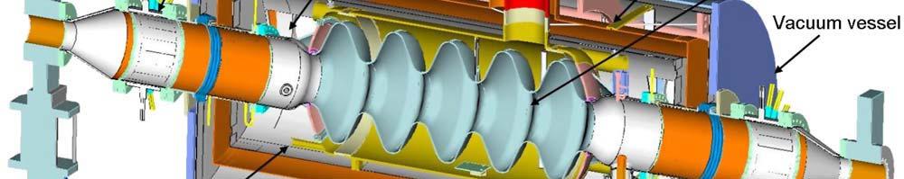
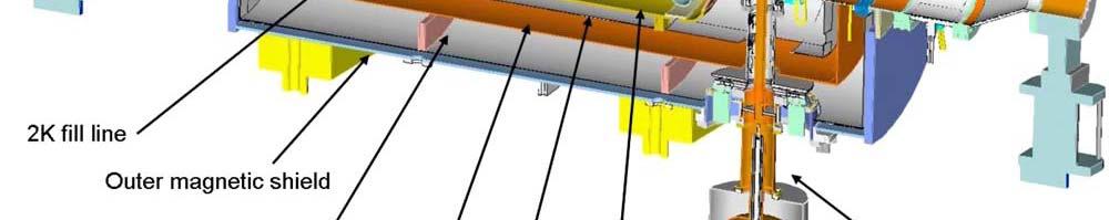
26 Electron cooler for RHIC SRF gun ERL cryomodule October 1, 2008 S. Belomestnykh: RF systems for CW SRF linacs 26


27 1 MW RF for SRF gun Parameters of VKP-7952B klystron (CPI): beam voltage A full power collector max. output power 1000 kw efficiency 65% gain >40 db bandwidth ±0.7 1 db WR1500 waveguide output October 1, 2008 S. Belomestnykh: RF systems for CW SRF linacs 27
28 HVPS IGBT based system that uses a Fast Shut Down Mode (FSDM) instead of a crowbar. Transmitter was manufactured by Continental Electronics. October 1, 2008 S. Belomestnykh: RF systems for CW SRF linacs 28


29 50 kw RF for ERL cavity broadcast transmitter manufactured by Thomson-BM (former Thales-BM) modified version TH793 Thales broadcast IOT October 1, 2008 S. Belomestnykh: RF systems for CW SRF linacs 29
 kw Linac amplifier power budget mdg 03/09/08 25")
30 SPIRAL-2 project Radioactive beam facility Protons: 33 MeV, 5 ma; deutrons: 40 MeV, 5 ma; heavy ions: 14.5 MeV/u, 1 ma 12 β = 0.07 QWR cavities 14 β = 0.12 QWR cavities Independently phased cavities for wide velocity acceptance and output energy optimization for each ion species SPIRAL-2 RF (THP048) kw Linac amplifier power budget mdg 03/09/08 25 Beam Loading or cavity loss Margin power +30% Amplifier and circulator power Net power REG 1 REG 2 REG 3 CA1 CA2 CA3 CA4 CA5 CA6 CA7 CA8 CA9 CA10 CA11 CA12 CB1 CB2 CB3 CB4 CB5 CB6 CB7 CB8 CB9 CB10 CB11 CB12 CB13 CB14 Utilized power equipment developed for FM market 3, 5.5, 10 & 20 kw amplifiers are available 3 1/8 50-Ohm transmission line, air cooled Test bench was designed and operated up to 20 kw The 10 kw prototype has been used at IPN-Orsay for β = 0.12 cryomodule test Class C amplifiers October 1, 2008 S. Belomestnykh: RF systems for CW SRF linacs 30


31 SPIRAL-2 RF system 3W 50 Ώ 50 Ώ 50 Ώ 3 kw 3kW Σ 3 kw 3 kw Σ 50 Ώ Σ 50 Ώ 50 Ώ RF monitors 50 Ω Circulator 10 kw amplifier architecture. t Circulators and dummy load are outside tid the amplifier cabinet, at high power level. Green elements are water cooled. Two 10 kw amplifiers. October 1, 2008 S. Belomestnykh: RF systems for CW SRF linacs 31


 352")


32 SOLEIL solid state HPA Could not resist to mention: 180 kw CW solid state amplifier for SOLEIL storage ring based light source (France) 352 MHz very reliable and stable operation efficiency ~50% October 1, 2008 S. Belomestnykh: RF systems for CW SRF linacs 32
33 Future projects More and more future projects are based on CW superconducting RF technology. Here is a sample list of such projects that utilize L band SRF linacs and will require medium to high power CW RF systems: STARS (BESSY) ERL@CESR (Cornell) KEK ERL 0.5 MW drive linac (TRIUMF) WiFEL (Wisconsin) October 1, 2008 S. Belomestnykh: RF systems for CW SRF linacs 33
34 Summary CW SRF linacs are used for a wide variety of scientific applications form nuclear physics to light source facilities to radio isotopes production. In all machines presented in this talk a simple architecture with one RF high power amplifier per cavity is used. Reasons: flexibility, available RF power sources, requirements to fiels stability, efficiency i of RF system,... Most of high-β linacs operate in L band. UHF band is left for ampere-class machines. IOTs successfully compete with klystrons at medium power levels due to their better efficiency and linearity. Solid state amplifiers are rapidly becoming the technology of choice in VHF band at medium power levels and making way into UHF and L bands (though they are still pricey and not very efficient there.) There are more CW SRF linac based projects under consideration at different laboratories. October 1, 2008 S. Belomestnykh: RF systems for CW SRF linacs 34
35 Acknowledgement I would like to thank people who provided information, slides and pictures for this talk: C. Hovater (Jlab) T. Powers (JLab) H. Buettig (Rossendorf) P. McIntosh (Daresbury) A. Zaltsman (BNL) M. Di Giacomo (GANIL) R. Laxdal (TRIUMF) October 1, 2008 S. Belomestnykh: RF systems for CW SRF linacs 35
36 End of talk October 1, 2008 S. Belomestnykh: RF systems for CW SRF linacs 36
37 Additional slides October 1, 2008 S. Belomestnykh: RF systems for CW SRF linacs 37
38 Precision HV PS (an example) LAMBDA developed a precision 75 kw, 25 kv switching HVPS for a klystron amplifier (reported at PAC 07) October 1, 2008 S. Belomestnykh: RF systems for CW SRF linacs 38

 VSWR 1.")
 25kV 30kV 36kV October 1,")
39 IOT manufacturers: CPI Features: Compact design CW or pulse operation 35kW CW or 80 kw pulse Easy installation Fast tube replacement (down time less than 1 hour) VSWR 1.3:1 efficie ency (%) Po(kW) 25kV 30kV 36kV October 1, 2008 S. Belomestnykh: RF systems for CW SRF linacs 39


40 IOT manufacturers: THALES October 1, 2008 S. Belomestnykh: RF systems for CW SRF linacs 40
41 IOT manufacturers: e2v Lifetime estimate Standard warranty period is 10,000 hrs Average life of 1213 broadcast IOTs is 31,700 hrs (for all e2v tubes that have recorded installation and removal date, tubes still in service are not included) October 1, 2008 S. Belomestnykh: RF systems for CW SRF linacs 41
IOT OPERATIONAL EXPERIENCE ON ALICE AND EMMA AT DARESBURY LABORATORY
 IOT OPERATIONAL EXPERIENCE ON ALICE AND EMMA AT DARESBURY LABORATORY A. Wheelhouse ASTeC, STFC Daresbury Laboratory ESLS XVIII Workshop, ELLETRA 25 th 26 th November 2010 Contents Brief Description ALICE
Experience with the Cornell ERL Injector SRF Cryomodule during High Beam Current Operation
 Experience with the Cornell ERL Injector SRF Cryomodule during High Beam Current Operation Matthias Liepe Assistant Professor of Physics Cornell University Experience with the Cornell ERL Injector SRF
INFN School on Electron Accelerators. RF Power Sources and Distribution
 INFN School on Electron Accelerators 12-14 September 2007, INFN Sezione di Pisa Lecture 7b RF Power Sources and Distribution Carlo Pagani University of Milano INFN Milano-LASA & GDE The ILC Double Tunnel
RF Upgrades & Experience At JLab. Rick Nelson
 RF Upgrades & Experience At JLab Rick Nelson Outline Background: CEBAF / Jefferson Lab History, upgrade requirements & decisions Progress & problems along the way Present status Future directions & concerns
RF plans for ESS. Morten Jensen. ESLS-RF 2013 Berlin
 RF plans for ESS Morten Jensen ESLS-RF 2013 Berlin Overview The European Spallation Source (ESS) will house the most powerful proton linac ever built. The average beam power will be 5 MW which is five
RF Power Klystrons & 20 Year Look. R. Nelson 7/15/15
 RF Power Klystrons & 20 Year Look R. Nelson 7/15/15 RF Power klystrons 8 x 13 kw klystrons Page 2 Why A klystron? Best (only) choice at the time - 1988 Easy to use: Input (drive), output (to CM), power
High Brightness Injector Development and ERL Planning at Cornell. Charlie Sinclair Cornell University Laboratory for Elementary-Particle Physics
 High Brightness Injector Development and ERL Planning at Cornell Charlie Sinclair Cornell University Laboratory for Elementary-Particle Physics June 22, 2006 JLab CASA Seminar 2 Background During 2000-2001,
Operating Experience and Reliability Improvements on the 5 kw CW Klystron at Jefferson Lab
 Operating Experience and Reliability Improvements on the 5 kw CW Klystron at Jefferson Lab Richard Walker & Richard Nelson Jefferson Lab, Newport News VA Jefferson Lab is a $600M Department of Energy facility
Diamond RF Status (RF Activities at Daresbury) Mike Dykes
 Mike Dykes") Diamond RF Status (RF Activities at Daresbury) Mike Dykes ASTeC What is it? What does it do? Diamond Status Linac Booster RF Storage Ring RF Summary Content ASTeC ASTeC was formed in 2001 as a centre of
Diamond RF Status (RF Activities at Daresbury) Mike Dykes ASTeC What is it? What does it do? Diamond Status Linac Booster RF Storage Ring RF Summary Content ASTeC ASTeC was formed in 2001 as a centre of
News from HZB / BESSY Wolfgang Anders at ESLS-RF Meeting September 2010 Trieste
 News from HZB / BESSY Wolfgang Anders at ESLS-RF Meeting September 2010 Trieste Outline Status Klystrons / IOT Modifications of transmitters New LINAC for BESSY II Status BERLinPro HoBiCaT Extension --
2 Work Package and Work Unit descriptions. 2.8 WP8: RF Systems (R. Ruber, Uppsala)
") 2 Work Package and Work Unit descriptions 2.8 WP8: RF Systems (R. Ruber, Uppsala) The RF systems work package (WP) addresses the design and development of the RF power generation, control and distribution
2 Work Package and Work Unit descriptions 2.8 WP8: RF Systems (R. Ruber, Uppsala) The RF systems work package (WP) addresses the design and development of the RF power generation, control and distribution
XFEL High Power RF System Recent Developments
 XFEL High Power RF System Recent Developments for the XFEL RF Group Outline XFEL RF System Requirements Overview Basic Layout RF System Main Components Multibeam Klystrons Modulator RF Waveguide Distribution
RF considerations for SwissFEL
 RF considerations for H. Fitze in behalf of the PSI RF group Workshop on Compact X-Ray Free Electron Lasers 19.-21. July 2010, Shanghai Agenda Introduction RF-Gun Development C-band development Summary
Detailed Design Report
 Detailed Design Report Chapter 4 MAX IV Injector 4.6. Acceleration MAX IV Facility CHAPTER 4.6. ACCELERATION 1(10) 4.6. Acceleration 4.6. Acceleration...2 4.6.1. RF Units... 2 4.6.2. Accelerator Units...
Pulsed Klystrons for Next Generation Neutron Sources Edward L. Eisen - CPI, Inc. Palo Alto, CA, USA
 Pulsed Klystrons for Next Generation Neutron Sources Edward L. Eisen - CPI, Inc. Palo Alto, CA, USA Abstract The U.S. Department of Energy (DOE) Office of Science has funded the construction of a new accelerator-based
Upgrade of CEBAF to 12 GeV
 Upgrade of CEBAF to 12 GeV Leigh Harwood (for 12 GeV Accelerator team) Page 1 Outline Background High-level description Schedule Sub-system descriptions and status Summary Page 2 CEBAF Science Mission
3 cerl. 3-1 cerl Overview. 3-2 High-brightness DC Photocathode Gun and Gun Test Beamline
 3 cerl 3-1 cerl Overview As described before, the aim of the cerl in the R&D program includes the development of critical components for the ERL, as well as the construction of a test accelerator. The
LLRF at SSRF. Yubin Zhao
 LLRF at SSRF Yubin Zhao 2017.10.16 contents SSRF RF operation status Proton therapy LLRF Third harmonic cavity LLRF Three LINAC LLRF Hard X FEL LLRF (future project ) Trip statistics of RF system Trip
RF Power Generation II
 RF Power Generation II Klystrons, Magnetrons and Gyrotrons Professor R.G. Carter Engineering Department, Lancaster University, U.K. and The Cockcroft Institute of Accelerator Science and Technology Scope
4.4 Injector Linear Accelerator
 4.4 Injector Linear Accelerator 100 MeV S-band linear accelerator based on the components already built for the S-Band Linear Collider Test Facility at DESY [1, 2] will be used as an injector for the CANDLE
A HIGH POWER LONG PULSE HIGH EFFICIENCY MULTI BEAM KLYSTRON
 A HIGH POWER LONG PULSE HIGH EFFICIENCY MULTI BEAM KLYSTRON A.Beunas and G. Faillon Thales Electron Devices, Vélizy, France S. Choroba DESY, Hamburg, Germany Abstract THALES ELECTRON DEVICES has developed
RF Power Upgrade at Jefferson Lab
 RF Power Upgrade at Jefferson Lab Rick Nelson*, Andrew Kimber *nelson@jlab.org * Notice: Authored by Jefferson Science Associates, LLC under U.S. DOE Contract No. DE- AC05-06OR23177. The U.S. Government
RUNNING EXPERIENCE OF FZD SRF PHOTOINJECTOR
 RUNNING EXPERIENCE OF FZD SRF PHOTOINJECTOR Rong Xiang On behalf of the BESSY-DESY-FZD-MBI collaboration and the ELBE team FEL 2009, Liverpool, United Kingdom, August 23 ~ 28, 2009 Outline Introduction
!"!3
 Abstract A single-mode 500 MHz superconducting cavity cryomodule has been developed at Cornell for the electronpositron collider/synchrotron light source CESR. The Cornell B-cell cavity belongs to the
Status of BESSY II and berlinpro. Wolfgang Anders. Helmholtz-Zentrum Berlin for Materials and Energy (HZB) 20th ESLS-RF Meeting
 20th ESLS-RF Meeting") Status of BESSY II and berlinpro Wolfgang Anders Helmholtz-Zentrum Berlin for Materials and Energy (HZB) 20th ESLS-RF Meeting 16.-17.11.2016 at PSI Outline BESSY II Problems with circulators Landau cavity
Status of BESSY II and berlinpro Wolfgang Anders Helmholtz-Zentrum Berlin for Materials and Energy (HZB) 20th ESLS-RF Meeting 16.-17.11.2016 at PSI Outline BESSY II Problems with circulators Landau cavity
TITLE PAGE. Title of paper: PUSH-PULL FEL, A NEW ERL CONCEPT Author: Andrew Hutton. Author Affiliation: Jefferson Lab. Requested Proceedings:
 TITLE PAGE Title of paper: PUSH-PULL FEL, A NEW ERL CONCEPT Author: Andrew Hutton Author Affiliation: Jefferson Lab Requested Proceedings: Unique Session ID: Classification Codes: Keywords: Energy Recovery,
SRS and ERLP developments. Andrew moss
 SRS and ERLP developments Andrew moss Contents SRS Status Latest news Major faults Status Energy Recovery Linac Prototype Latest news Status of the RF system Status of the cryogenic system SRS Status Machine
IOT RF Power Sources for Pulsed and CW Linacs
 LINAC 2004 Lübeck, August 16 20, 2004 IOT RF Power Sources H. Bohlen, Y. Li, Bob Tornoe Communications & Power Industries Eimac Division, San Carlos, CA, USA Linac RF source property requirements (not
Current status of XFEL/SPring-8 project and SCSS test accelerator
 Current status of XFEL/SPring-8 project and SCSS test accelerator Takahiro Inagaki for XFEL project in SPring-8 inagaki@spring8.or.jp Outline (1) Introduction (2) Key technology for compactness (3) Key
ILC-LNF TECHNICAL NOTE
 IL-LNF EHNIAL NOE Divisione Acceleratori Frascati, July 4, 2006 Note: IL-LNF-001 RF SYSEM FOR HE IL DAMPING RINGS R. Boni, INFN-LNF, Frascati, Italy G. avallari, ERN, Geneva, Switzerland Introduction For
The ESS Accelerator. For Norwegian Industry and Research. Oslo, 24 Sept Håkan Danared Deputy Head Accelerator Division Group Leader Beam Physics
 The ESS Accelerator For Norwegian Industry and Research Oslo, 24 Sept 2013 Håkan Danared Deputy Head Accelerator Division Group Leader Beam Physics The Hadron Intensity Frontier Courtesy of M. Seidel (PSI)
NSLS-II RF Systems James Rose, Radio Frequency Group Leader PAC 2011
 NSLS-II RF Systems James Rose, Radio Frequency Group Leader PAC 2011 1 BROOKHAVEN SCIENCE ASSOCIATES Introduction Linac RF cavities and klystrons Booster Cavity-Transmitter Storage Ring 500 MHz SRF cavity
RF Solutions for Science.
 RF Solutions for Science www.thalesgroup.com State-of-the-art RF sources for your scientific needs High-power klystrons HIGH KLYSTRONS WITH RF LONG PULSE above 50 μs Thales has been one of the leading
The Elettra Storage Ring and Top-Up Operation
 The Elettra Storage Ring and Top-Up Operation Emanuel Karantzoulis Past and Present Configurations 1994-2007 From 2008 5000 hours /year to the users 2010: Operations transition year Decay mode, 2 GeV (340mA)
DESIGN AND PERFORMANCE OF L-BAND AND S-BAND MULTI BEAM KLYSTRONS
 DESIGN AND PERFORMANCE OF L-BAND AND S-BAND MULTI BEAM KLYSTRONS Y. H. Chin, KEK, Tsukuba, Japan. Abstract Recently, there has been a rising international interest in multi-beam klystrons (MBK) in the
Electron linac photo-fission driver for rare isotope program at TRIUMF
 Canada s national laboratory for particle and nuclear physics Laboratoire national canadien pour la recherche en physique nucléaire et en physique des particules Electron linac photo-fission driver for
STATUS AND COMMISSIONING RESULTS OF THE R&D ERL AT BNL*
 STATUS AND COMMISSIONING RESULTS OF THE R&D ERL AT BNL* D. Kayran #,1,2, Z. Altinbas 1, D. Beavis 1, S. Belomestnykh 1,2, I. Ben-Zvi 1,2, S. Deonarine 1, D.M. Gassner 1, R. C. Gupta 1, H. Hahn 1,L.R. Hammons
The PEFP 20-MeV Proton Linear Accelerator
 Journal of the Korean Physical Society, Vol. 52, No. 3, March 2008, pp. 721726 Review Articles The PEFP 20-MeV Proton Linear Accelerator Y. S. Cho, H. J. Kwon, J. H. Jang, H. S. Kim, K. T. Seol, D. I.
Welcome and FRIB Project Status. FRIB Highlights and Plan Ahead
 Welcome and FRIB Project Status Thomas Glasmacher Project Manager This material is based upon work supported by the U.S. Department of Energy Office of Science under Cooperative Agreement DE-SC0000661.
High Rep Rate Guns: FZD Superconducting RF Photogun
 High Rep Rate Guns: FZD Superconducting RF Photogun J. Teichert, A. Arnold, H. Büttig, D. Janssen, M. Justus, U. Lehnert, P. Michel, K. Moeller, P. Murcek, Ch. Schneider, R. Schurig, G. Staats, F. Staufenbiel,
Upgrading LHC Luminosity
 1 Upgrading LHC Luminosity 2 Luminosity (cm -2 s -1 ) Present (2011) ~2 x10 33 Beam intensity @ injection (*) Nominal (2015?) 1 x 10 34 1.1 x10 11 Upgraded (2021?) ~5 x10 34 ~2.4 x10 11 (*) protons per
L-Band RF R&D. SLAC DOE Review June 15 th, Chris Adolphsen SLAC
 L-Band RF R&D SLAC DOE Review June 15 th, 2005 Chris Adolphsen SLAC International Linear Collider (ILC) RF Unit (TESLA TDR Layout) Gradient = 23.4 MV/m Bunch Spacing = 337 ns Fill Time = 420 µs Train Length
Status of RF Power and Acceleration of the MAX IV - LINAC
 Status of RF Power and Acceleration of the MAX IV - LINAC Dionis Kumbaro ESLS RF Workshop 2015 MAX IV Laboratory A National Laboratory for synchrotron radiation at Lunds University 1981 MAX-lab is formed
Proton Engineering Frontier Project
 Proton Engineering Frontier Project OECD Nuclear Energy Agency Fifth International Workshop on the Utilisation and Reliability of High Power Proton Accelerators (HPPA5) (6-9 May 2007, Mol, Belgium) Yong-Sub
9th ESLS RF Meeting September ALBA RF System. F. Perez. RF System 1/20
 ALBA RF System F. Perez RF System 1/20 ALBA Synchrotron Light Source in Barcelona (Spain) 3 GeV accelerator 30 beamlines (7 on day one) 50-50 Spanish Government Catalan Government First beam for users
KEKB INJECTOR LINAC AND UPGRADE FOR SUPERKEKB
 KEKB INJECTOR LINAC AND UPGRADE FOR SUPERKEKB S. Michizono for the KEK electron/positron Injector Linac and the Linac Commissioning Group KEK KEKB injector linac Brief history of the KEK electron linac
Present Status and Future Upgrade of KEKB Injector Linac
 Present Status and Future Upgrade of KEKB Injector Linac Kazuro Furukawa, for e /e + Linac Group Present Status Upgrade in the Near Future R&D towards SuperKEKB 1 Machine Features Present Status and Future
Design Studies For The LCLS 120 Hz RF Gun Injector
 BNL-67922 Informal Report LCLS-TN-01-3 Design Studies For The LCLS 120 Hz RF Gun Injector X.J. Wang, M. Babzien, I. Ben-Zvi, X.Y. Chang, S. Pjerov, and M. Woodle National Synchrotron Light Source Brookhaven
Technology Challenges for SRF Guns as ERL Sources in View of Rossendorf work
 Technology Challenges for SRF Guns as ERL Sources in View of Rossendorf work, Hartmut Buettig, Pavel Evtushenko, Ulf Lehnert, Peter Michel, Karsten Moeller, Petr Murcek, Christof Schneider, Rico Schurig,
Digital BPMs and Orbit Feedback Systems
 Digital BPMs and Orbit Feedback Systems, M. Böge, M. Dehler, B. Keil, P. Pollet, V. Schlott Outline stability requirements at SLS storage ring digital beam position monitors (DBPM) SLS global fast orbit
The TESLA RF System. S. Choroba. for the TESLA Collaboration. DESY Notkestr. 85, D Hamburg, Germany
 The TESLA RF System S. Choroba for the TESLA Collaboration DESY Notkestr. 85, D-22603 Hamburg, Germany Abstract. The TESLA project proposed by the TESLA collaboration in 2001 is a 500 to 800GeV e+/e- linear
Towards an X-Band Power Source at CERN and a European Structure Test Facility
 Towards an X-Band Power Source at CERN and a European Structure Test Facility Erk Jensen and Gerry McMomagle CERN The X-Band Accelerating Structure Design and Test-Program Workshop Day 2: Structure Testing
LCLS RF Reference and Control R. Akre Last Update Sector 0 RF and Timing Systems
 LCLS RF Reference and Control R. Akre Last Update 5-19-04 Sector 0 RF and Timing Systems The reference system for the RF and timing starts at the 476MHz Master Oscillator, figure 1. Figure 1. Front end
Jefferson Lab Experience with Beam Halo, Beam Loss, etc.
 Jefferson Lab Experience with Beam Halo, Beam Loss, etc. Pavel Evtushenko with a lot of input from many experienced colleagues Steve Benson, Dave Douglas, Kevin Jordan, Carlos Hernandez-Garcia, Dan Sexton,
IOT Charakterization at BESSY ( HZB)
") IOT Charakterization at BESSY ( HZB) Agenda: Wolfgang Anders, Hans Georg Hoberg, Andreas Heugel BESSY, Berlin ESLS-RF Workshop 1.-2.10.2008 Diamond BESSY + HMI HZB MLS in Operation Bessy Transmitter IOT
IOT Charakterization at BESSY ( HZB) Agenda: Wolfgang Anders, Hans Georg Hoberg, Andreas Heugel BESSY, Berlin ESLS-RF Workshop 1.-2.10.2008 Diamond BESSY + HMI HZB MLS in Operation Bessy Transmitter IOT
Low Level RF for PIP-II. Jonathan Edelen LLRF 2017 Workshop (Barcelona) 16 Oct 2017
 16 Oct 2017") Low Level RF for PIP-II Jonathan Edelen LLRF 2017 Workshop (Barcelona) 16 Oct 2017 PIP-II LLRF Team Fermilab Brian Chase, Edward Cullerton, Joshua Einstein, Jeremiah Holzbauer, Dan Klepec, Yuriy Pischalnikov,
Low Level RF for PIP-II Jonathan Edelen LLRF 2017 Workshop (Barcelona) 16 Oct 2017 PIP-II LLRF Team Fermilab Brian Chase, Edward Cullerton, Joshua Einstein, Jeremiah Holzbauer, Dan Klepec, Yuriy Pischalnikov,
Evaluation of Performance, Reliability, and Risk for High Peak Power RF Sources from S-band through X-band for Advanced Accelerator Applications
 Evaluation of Performance, Reliability, and Risk for High Peak Power RF Sources from S-band through X-band for Advanced Accelerator Applications Michael V. Fazio C. Adolphsen, A. Jensen, C. Pearson, D.
18 GHz, 2.2 kw KLYSTRON GENERATOR GKP 24KP 18GHz WR62 3x400V
 18 GHz, 2.2 kw KLYSTRON GENERATOR GKP 24KP 18GHz WR62 3x400V With its characteristics of power stability whatever the load, very fast response time when pulsed (via external modulated signal), low ripple,
Status of SOLARIS. Paweł Borowiec On behalf of Solaris Team
 Status of SOLARIS Paweł Borowiec On behalf of Solaris Team e-mail: pawel.borowiec@uj.edu.pl XX ESLS-RF Meeting, Villingen 16-17.11.2016 Outline 1. Timeline 2. Injector 3. Storage ring 16-17.11.2016 XX
PoS(EPS-HEP2015)525. The RF system for FCC-ee. A. Butterworth CERN 1211 Geneva 23, Switzerland
525. The RF system for FCC-ee. A. Butterworth CERN 1211 Geneva 23, Switzerland") CERN 1211 Geneva 23, Switzerland E-mail: andrew.butterworth@cern.ch O. Brunner CERN 1211 Geneva 23, Switzerland E-mail: olivier.brunner@cern.ch R. Calaga CERN 1211 Geneva 23, Switzerland E-mail: rama.calaga@cern.ch
CERN 1211 Geneva 23, Switzerland E-mail: andrew.butterworth@cern.ch O. Brunner CERN 1211 Geneva 23, Switzerland E-mail: olivier.brunner@cern.ch R. Calaga CERN 1211 Geneva 23, Switzerland E-mail: rama.calaga@cern.ch
KARA and FLUTE RF Overview/status
 KARA and FLUTE RF Overview/status Nigel Smale on behalf of IBPT and LAS teams Laboratory for Applications of Synchrotron radiation (LAS) Institute for Beam Physics and Technology (IBPT) KARA KIT The Research
CLIC Feasibility Demonstration at CTF3
 CLIC Feasibility Demonstration at CTF3 Roger Ruber Uppsala University, Sweden, for the CLIC/CTF3 Collaboration http://cern.ch/clic-study LINAC 10 MO303 13 Sep 2010 The Key to CLIC Efficiency NC Linac for
Solid State Modulators for X-Band Accelerators
 Solid State Modulators for X-Band Accelerators John Kinross-Wright Diversified Technologies, Inc. Bedford, Massachusetts DTI X-Band Experience Developed and built two completely different NLC-class modulator
THE NEXT LINEAR COLLIDER TEST ACCELERATOR: STATUS AND RESULTS * Abstract
 SLAC PUB 7246 June 996 THE NEXT LINEAR COLLIDER TEST ACCELERATOR: STATUS AND RESULTS * Ronald D. Ruth, SLAC, Stanford, CA, USA Abstract At SLAC, we are pursuing the design of a Next Linear Collider (NLC)
STATUS OF THE SWISSFEL C-BAND LINEAR ACCELERATOR
 Proceedings of FEL213, New York, NY, USA STATUS OF THE SWISSFEL C-BAND LINEAR ACCELERATOR F. Loehl, J. Alex, H. Blumer, M. Bopp, H. Braun, A. Citterio, U. Ellenberger, H. Fitze, H. Joehri, T. Kleeb, L.
The FAIR plinac RF Systems
 The FAIR plinac RF Systems Libera Workshop Sep. 2011 Gerald Schreiber Gerald Schreiber, GSI RF Department 2 (1) Overview GSI / FAIR (2) FAIR Proton Linear Accelerator "plinac" (3) plinac RF Systems (4)
Design and Simulation of High Power RF Modulated Triode Electron Gun. A. Poursaleh
 Design and Simulation of High Power RF Modulated Triode Electron Gun A. Poursaleh National Academy of Sciences of Armenia, Institute of Radio Physics & Electronics, Yerevan, Armenia poursaleh83@yahoo.com
The basic parameters of the pre-injector are listed in the Table below. 100 MeV
 3.3 The Pre-injector The high design brightness of the SLS requires very high phase space density of the stored electrons, leading to a comparatively short lifetime of the beam in the storage ring. This,
PEP II Design Outline
 PEP II Design Outline Balša Terzić Jefferson Lab Collider Review Retreat, February 24, 2010 Outline General Information Parameter list (and evolution), initial design, upgrades Collider Ring Layout, insertions,
A New 4MW LHCD System for EAST
 1 EXW/P7-29 A New 4MW LHCD System for EAST Jiafang SHAN 1), Yong YANG 1), Fukun LIU 1), Lianmin ZHAO 1) and LHCD Team 1) 1) Institute of Plasma Physics, Chinese Academy of Sciences, Hefei, China E-mail
Design of the linear accelerator for the MYRRHA project
 MYRRHA Multipurpose hybrid Research Reactor for High-tech Applications Design of the linear accelerator for the MYRRHA project Roberto Salemme ADT - Outline What is MYRRHA? MYRRHA accelerator: requirements
14 GHz, 2.2 kw KLYSTRON GENERATOR GKP 22KP 14GHz WR62 3x400V
 14 GHz, 2.2 kw KLYSTRON GENERATOR GKP 22KP 14GHz WR62 3x400V With its characteristics of power stability independent of the load, very fast response time when pulsed (via external modulated signal), low
ANKA RF System - Upgrade Strategies
 ANKA RF System - Upgrade Strategies Vitali Judin ANKA Synchrotron Radiation Facility 2014-09 - 17 KIT University of the State Baden-Wuerttemberg and National Laboratory of the Helmholtz Association www.kit.edu
Pulses inside the pulse mode of operation at RF Gun
 Pulses inside the pulse mode of operation at RF Gun V. Vogel, V. Ayvazyan, K. Floettmann, D. Lipka, P. Morozov, H. Schlarb, S. Schreiber FLASH Seminar, DESY March 29, 2011 Contents Why we need a PiPmode
Spear3 RF System Sam Park 11/06/2003. Spear3 RF System. High Power Components Operation and Control. RF Requirement.
 Spear3 RF System RF Requirement Overall System High Power Components Operation and Control SPEAR 3 History 1996 Low emittance lattices explored 1996 SPEAR 3 proposed 11/97 SPEAR 3 design study team formed
45 MW, 22.8 GHz Second-Harmonic Multiplier for High-Gradient Tests*
 US High Gradient Research Collaboration Workshop. SLAC, May 23-25, 2007 45 MW, 22.8 GHz Second-Harmonic Multiplier for High-Gradient Tests* V.P. Yakovlev 1, S.Yu. Kazakov 1,2, and J.L. Hirshfield 1,3 1
TECHNICAL SPECIFICATION Multi-beam S-band Klystron type BT267
 TECHNICAL SPECIFICATION Multi-beam S-band Klystron type BT267 The company was created for the development and manufacture of precision microwave vacuum-electron-tube devices (VETD). The main product areas
SRF-gun Development Overview. J. Sekutowicz 17 th September, 2015 SRF15, Whistler, Canada
 SRF-gun Development Overview J. Sekutowicz 17 th September, 2015 SRF15, Whistler, Canada Acknowledgment Many thanks to: A. Arnold, J. Hao, E. Kako, T. Konomi, D. Kostin, J. Lorkiewicz, A. Neumann, J. Teichert
5 Project Costs and Schedule
 93 5 Project Costs and Schedule 5.1 Overview The cost evaluation for the integrated version of the XFEL with 30 experiments and 35 GeV beam energy as described in the TDR-2001 yielded 673 million EUR for
Technology Challenges for SRF Guns as ERL Source in View of BNL Work
 Technology Challenges for SRF Guns as ERL Source in View of BNL Work Work being performed and supported by the Collider Accelerator Division of Brookhaven National Labs as well as the Office of Naval Research
DELIVERY RECORD. Location: Ibaraki, Japan
 DELIVERY RECORD Client: Japan Atomic Energy Agency (JAEA) High Energy Accelerator Research Organization (KEK) Facility: J-PARC (Japan Proton Accelerator Research Complex) Location: Ibaraki, Japan 1 October
Commissioning of Accelerators. Dr. Marc Munoz (with the help of R. Miyamoto, C. Plostinar and M. Eshraqi)
") Commissioning of Accelerators Dr. Marc Munoz (with the help of R. Miyamoto, C. Plostinar and M. Eshraqi) www.europeanspallationsource.se 6 July, 2017 Contents General points Definition of Commissioning
Commissioning of Accelerators Dr. Marc Munoz (with the help of R. Miyamoto, C. Plostinar and M. Eshraqi) www.europeanspallationsource.se 6 July, 2017 Contents General points Definition of Commissioning
Dark current and multipacting trajectories simulations for the RF Photo Gun at PITZ
 Dark current and multipacting trajectories simulations for the RF Photo Gun at PITZ Introduction The PITZ RF Photo Gun Field simulations Dark current simulations Multipacting simulations Summary Igor Isaev
WG2 Group Summary. Chris Adolphsen Terry Garvey Hitoshi Hayano
 WG2 Group Summary Chris Adolphsen Terry Garvey Hitoshi Hayano Linac Options Fest On Thursday afternoon, various experts summarized the linac baseline options. Although hard choices have yet to be made,
Next Linear Collider. The 8-Pack Project. 8-Pack Project. Four 50 MW XL4 X-band klystrons installed on the 8-Pack
 The Four 50 MW XL4 X-band klystrons installed on the 8-Pack The Demonstrate an NLC power source Two Phases: 8-Pack Phase-1 (current): Multi-moded SLED II power compression Produce NLC baseline power: 475
Linac upgrade plan using a C-band system for SuperKEKB
 Linac upgrade plan using a C-band system for SuperKEKB S. Fukuda, M. Akemono, M. Ikeda, T. Oogoe, T. Ohsawa, Y. Ogawa, K. Kakihara, H. Katagiri, T. Kamitani, M. Sato, T. Shidara, A. Shirakawa, T. Sugimura,
The LEP Superconducting RF System
 The LEP Superconducting RF System K. Hübner* for the LEP RF Group CERN The basic components and the layout of the LEP rf system for the year 2000 are presented. The superconducting system consisted of
Status of CTF3. G.Geschonke CERN, AB
 Status of CTF3 G.Geschonke CERN, AB CTF3 layout CTF3 - Test of Drive Beam Generation, Acceleration & RF Multiplication by a factor 10 Drive Beam Injector ~ 50 m 3.5 A - 2100 b of 2.33 nc 150 MeV - 1.4
650MHz/800kW Klystron Development at IHEP
 650MHz/800kW Klystron Development at IHEP Shilun Pei, IHEP On behalf of HERSC (High Efficiency RF Source R&D Collaboration) in China Presentation at the IAS Program on High Energy Physics January 22, 2018,
DEVELOPMENT OF A 10 MW SHEET BEAM KLYSTRON FOR THE ILC*
 DEVELOPMENT OF A 10 MW SHEET BEAM KLYSTRON FOR THE ILC* D. Sprehn, E. Jongewaard, A. Haase, A. Jensen, D. Martin, SLAC National Accelerator Laboratory, Menlo Park, CA 94020, U.S.A. A. Burke, SAIC, San
Jae-Young Choi On behalf of PLS-II Linac team
 PLS-II Linac 2015. 4. 8. Jae-Young Choi On behalf of PLS-II Linac team Accelerators in Pohang Accelerator Laboratory XFEL (under construction) 400 M$ Machines under installation PLS-II PAL : Chronology
Performance of a DC GaAs photocathode gun for the Jefferson lab FEL
 Nuclear Instruments and Methods in Physics Research A 475 (2001) 549 553 Performance of a DC GaAs photocathode gun for the Jefferson lab FEL T. Siggins a, *, C. Sinclair a, C. Bohn b, D. Bullard a, D.
SUMMARY OF THE ILC R&D AND DESIGN
 SUMMARY OF THE ILC R&D AND DESIGN B. C. Barish, California Institute of Technology, USA Abstract The International Linear Collider (ILC) is a linear electron-positron collider based on 1.3 GHz superconducting
ESS Linac WP8 Radio Frequency Systems and Test Facilities
 ESS Linac WP8 Radio Frequency Systems and Test Facilities ESS TAC Lund, 8 July 2010 Roger Ruber (Uppsala University) for the ESS Linac RF Team Outline Work Package description Objectives Organization Technical
DESIGN OF 1.2-GEV SCL AS NEW INJECTOR FOR THE BNL AGS*
 DESIGN OF 1.2-GEV SCL AS NEW INJECTOR FOR THE BNL AGS* A. G. Ruggiero, J. Alessi, M. Harrison, M. Iarocci, T. Nehring, D. Raparia, T. Roser, J. Tuozzolo, W. Weng. Brookhaven National Laboratory, PO Box
Development of Multiple Beam Guns for High Power RF Sources for Accelerators and Colliders
 SLAC-PUB-10704 Development of Multiple Beam Guns for High Power RF Sources for Accelerators and Colliders R. Lawrence Ives*, George Miram*, Anatoly Krasnykh @, Valentin Ivanov @, David Marsden*, Max Mizuhara*,
ESS: The Machine. Bucharest, 24 April Håkan Danared Deputy Head Accelerator Division. H. Danared Industry & Partner Days Bucharest Page 1
 ESS: The Machine Bucharest, 24 April 2014 Håkan Danared Deputy Head Accelerator Division H. Danared Industry & Partner Days Bucharest Page 1 2025 ESS construction complete 2009 Decision: ESS will be built
The ALS RF systems, upgrades and ALS-U plans
 The ALS RF systems, upgrades and ALS-U plans M. Betz*, K. Baptiste, Q. Du, M. Vinco, S. Virostek 06/27/2018, CWRF2018, Hsinchu, Taiwan * mbetz@lbl.gov Outline Structure of this talk RF systems in the Advanced
CEBAF Accelerator Update. Michael Tiefenback CASA Accelerator Physics Experimental Liaison June 14, 2017
 CEBAF Accelerator Update Michael Tiefenback CASA Accelerator Physics Experimental Liaison June 14, 2017 CLAS12 Collaboration Meeting, June 13-16, 2017 1 Accelerator Division Leadership On April 30 Andrew
ESS Linac WP8 Radio Frequency Systems and Test Facilities
 ESS Linac WP8 Radio Frequency Systems and Test Facilities ESS/SPL Collaboration Meeting Lund, 29 June 2010 Roger Ruber (Uppsala University) for the ESS Linac RF Team ESS Linac WP8: RF Systems Outline Work