A Proof of Concept - Challenges of testing high-speed interface on wafer at lower cost
|
|
|
- Griffin Knight
- 5 years ago
- Views:
Transcription
1 A Proof of Concept - Challenges of testing high-speed interface on wafer at lower cost How to expand the bandwidth of the cantilever probe card Sony LSI Design Inc.
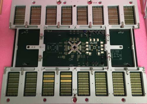
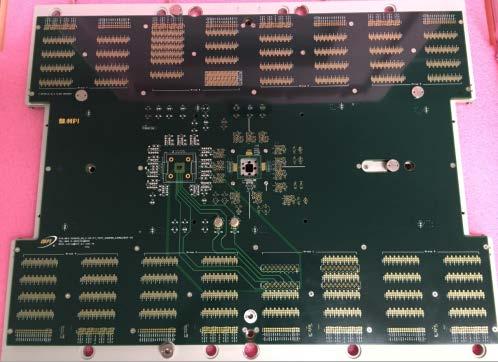


2 Introduction Design & Simulation PCB Fabrication Probe Assembly Whole probe card does not always have expected bandwidth!! 2


3 This presentation is based on User's point of view Software Hardware Measurement Expand Bandwidth at low-cost 3
4 Outline Background Overview Use case study Discussion of Results Conclusion 4
5 Outline Background Overview Use case study Discussion of Results Conclusion 5
6 Background wearable/mobile market with higher CAGR conducts has Higher data rate, Lower power, Smaller die size Lower cost Under the cost pressure deliver innovative devices with leading-edge features deliver into the market keeping a timely manner Need taking a balance of quality and cost test strategy with saving NRE cost judge at early phase with either "design assurance" or "testing assurance 6
7 Outline Background Overview Use case study Discussion of Results Conclusion 7
8 Overview What have we developed? Cantilever-type Probe card for Direct- Probe Methodology of expanding the bandwidth What is the point? Adapt both high speed and low cost Measurement and Mathematics 8

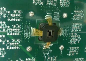
9 What is Direct-Probe? ATE Legacy Probe system ATE Direct-Probe system Tester Head mother board Pogo Tower Probe Card Prober Not having Pogo tower To minimize the number of interconnects 9
10 Outline Background Overview Use case study Discussion of Results Conclusion 10
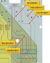
11 Use case study Case1(ideal) Case2(un-friendly) Probe Probe PCB PCB GSSG pad layout GSSS pad layout 11

12 Case1(ideal) Use case study GSSG pad layout GSSG pad layout Measurement environment Calibration method S-parameter measurement Eye diagram Expand bandwidth 12
13 Measurement environment Overview Top side Measurement setup Stiffener fixture Microscope Manipulator Micro positioner Network Analyzer Bottom side 13


14 Calibration method Typical case Actual Case DUT side VNA Cable RF prob e VNA Cable RF prob e Tester side Due to different pitches, We cannot use calibration board!! Reference plane Reference plane 14

15 Calibration method Actual Case DUT side Tester side different pitches 1xx um 1250 um VNA Cable RF prob e De-embedding using RF-probe s S-parameter Reference plane 15

) db(s(2,1)) -20-30 db(s(1,1)) db(s(2,1)) -20-30 -40-40")


16 Measurement result Simulation result PCB measurement Probe card measurement 0 Forward Transmission, db 0 Forward Transmission, db 0 Forward Transmission, db db(s(1,1)) db(s(2,1)) db(s(1,1)) db(s(2,1)) db(s(1,1)) db(s(2,1)) freq, GHz S21=6.81GHz@-3dB S11=8.10GHz@-10dB freq, GHz S21= 5.35GHz@-3dB S11=15.19GHz@-10dB freq, GHz S21=4.84GHz@-3dB S11=9.61GHz@-10dB Enough bandwidth as targeted 16
17 Eye-diagram result Ideal case (GSSG) 2Gbps,PRBS 5Gbps,PRBS 10Gbps,PRBS measured Input DUT Probe card Output Tester We see Eye-opening at 10Gbps, but it might cause a low-yield in case of production. 17

 Even at 10Gbps, Functional Test is")
18 Expand bandwidth Ideal case (GSSG) 2Gbps,PRBS 5Gbps,PRBS 10Gbps,PRBS Before Input Output After Probe DUT Tester card Applying cancel out Cancel out Using measured S-para (mathematics) Even at 10Gbps, Functional Test is OK!! 18
19 How can we cancel out? Same as SI simulation methodology Mathematically put-in the transmission line Measured Simulated A B FFT Transmission line (S-parameter) IFFT 19
20 How can we cancel out? Moving observation point methodology Mathematically cancel out Similar to oscilloscope function Simulated Measured A B IFFT Transmission line (S-parameter) FFT 20

21 GSSS pad layout Use case study Case2(un-friendly) Measurement environment S-parameter measurement Eye diagram Expand bandwidth GSSS pad layout 21


22 GSSS Measurement environment Overview Top side Measurement setup Stiffener fixture Microscope Manipulator Micro positioner Network Analyzer Bottom side 22


23 GSSS Measurement setup Single x2, Single x2 Single x2, Dual x1 RF-probe to via Calibration VNA Cable RF-probe on probe RF prob e RF-probe to via RF-probe on probe Reference plane De-embedding using RF-probe s S-parameter 23


24 GSSS Measurement result Single x2, Single x2 Single x2, Dual x1 S21= S11= S21= S11= Case1(GSSG) result S21=4.84GHz S11=9.61GHz Dual-type is better 24
25 GSSS Eye-diagram result Un-friendly case (GSSS) 2Gbps,PRBS 5Gbps,PRBS 10Gbps,PRBS measured Input DUT Probe card Output Tester We see eye-opening at 10Gbps, but it might cause a low-yield in case of production. 25
")


26 GSSS Expand bandwidth Un-friendly case (GSSS) 2Gbps,PRBS 5Gbps,PRBS 10Gbps,PRBS Before Input Cancel out Output After DUT Probe card Tester Apply worse S-parameter we cannot cancel out 26
")


27 GSSS Expand bandwidth Un-friendly case (GSSS) 2Gbps,PRBS 5Gbps,PRBS 10Gbps,PRBS Before Input DUT Cancel out Probe card Output Tester After Apply better S-parameter we can cancel out 27
28 Outline Introduction Background Overview Development Use case study Discussion of Results Conclusion 28


29 Discussion of GSSS-Results what makes the results so different? STUB STUB 29
30 Outline Introduction Background Overview Development Use case study Discussion of Results Conclusion 30
31 Conclusion We have developed a cantilever-type probe card saving much NRE cost. Measuring S-parameters should carefully be done in case of un-friendly pad layout. By applying cancel out methodology, we can test even at 10Gbps in Production. 31


32 Thank you!! Q&A 32
DUT ATE Test Fixture S-Parameters Estimation using 1x-Reflect Methodology
 DUT ATE Test Fixture S-Parameters Estimation using 1x-Reflect Methodology Jose Moreira, Advantest Ching-Chao Huang, AtaiTec Derek Lee, Nvidia Conference Ready mm/dd/2014 BiTS China Workshop Shanghai September
Verification of HBM through Direct Probing on MicroBumps
 Verification of HBM through Direct Probing on MicroBumps FormFactor Sung Wook Moon SK hynix Outline HBM market HBM test flow Device structure overview Key test challenges addressed Signal delivery and
PCB Probing for Signal-Integrity Measurements
 TITLE PCB Probing for Signal-Integrity Measurements Richard Zai, PacketMicro Image PCB Probing for Signal-Integrity Measurements Richard Zai, PacketMicro Richard Zai, Ph.D. CTO, PacketMicro rzai@packetmicro.com
GT Dual-Row Nano Vertical Thru-Hole High Speed Characterization Report For Differential Data Applications
 GT-16-97 Dual-Row Nano Vertical Thru-Hole For Differential Data Applications 891-007-15S Vertical Thru-Hole PCB 891-001-15P Cable Mount Revision History Rev Date Approved Description A 8/31/2016 R. Ghiselli/G.
RF Characterization Report
 CJT Series Circular RF Twinax Jack CJT-T-P-HH-ST-TH1 CJT-T-P-HH-RA-BH1 Mated With C28S-XX.XX-SPS8-SPS8 Description: Fully Mated Circular RF Shielded Twisted Pair Twinax Cable Assembly Samtec Inc. WWW.SAMTEC.COM
De-embedding Techniques For Passive Components Implemented on a 0.25 µm Digital CMOS Process
 PIERS ONLINE, VOL. 3, NO. 2, 27 184 De-embedding Techniques For Passive Components Implemented on a.25 µm Digital CMOS Process Marc D. Rosales, Honee Lyn Tan, Louis P. Alarcon, and Delfin Jay Sabido IX
GT Dual-Row Nano Vertical SMT High Speed Characterization Report For Differential Data Applications
 GT-16-95 Dual-Row Nano Vertical SMT For Differential Data Applications 891-011-15S Vertical SMT PCB 891-001-15P Cable Mount Revision History Rev Date Approved Description A 6/3/2016 R. Ghiselli/D. Armani
30 GHz Attenuator Performance and De-Embedment
 30GHz De-Embedment Application Note - Page 1 of 6 Theory of De-Embedment. Due to the need for smaller packages and higher signal integrity a vast majority of todays RF and Microwave components are utilizing
In-situ Port Cal for Dual Carriages Tuner
 In-situ Port Cal for Dual Carriages Tuner In-Situ port cal method is the calibration technique mainly for cascaded tuners or multi-carriage tuner. Unlike in-situ system cal which requires 2 VNA calibrations
SCSI Cable Characterization Methodology and Systems from GigaTest Labs
 lide - 1 CI Cable Characterization Methodology and ystems from GigaTest Labs 134. Wolfe Rd unnyvale, CA 94086 408-524-2700 www.gigatest.com lide - 2 Overview Methodology summary Fixturing Instrumentation
Senior Project Manager / AEO
 Kenny Liao 2018.12.18&20 Senior Project Manager / AEO Measurement Demo Prepare instrument for measurement Calibration Fixture removal Conclusion What next? Future trends Resources Acquire channel data
Designing High Performance Interposers with 3-port and 6-port S-parameters
 DesignCon 2015 Designing High Performance Interposers with 3-port and 6-port S-parameters Joseph Socha, Nexus Technology joe.socha@nexustechnology.com Jonathan Dandy, Tektronix jonathan.s.dandy@tektronix.com
RF (Wireless) Fundamentals 1- Day Seminar
 Fundamentals 1- Day Seminar") RF (Wireless) Fundamentals 1- Day Seminar In addition to testing Digital, Mixed Signal, and Memory circuitry many Test and Product Engineers are now faced with additional challenges: RF, Microwave and
RF (Wireless) Fundamentals 1- Day Seminar In addition to testing Digital, Mixed Signal, and Memory circuitry many Test and Product Engineers are now faced with additional challenges: RF, Microwave and
RF Characterization Report
 BNC7T-J-P-xx-ST-EMI BNC7T-J-P-xx-RD-BH1 BNC7T-J-P-xx-ST-TH1 BNC7T-J-P-xx-ST-TH2D BNC7T-J-P-xx-RA-BH2D Mated with: RF179-79SP1-74BJ1-0300 Description: 75 Ohm BNC Board Mount Jacks Samtec, Inc. 2005 All
Microwave Interconnect Testing For 12G SDI Applications
 TITLE Microwave Interconnect Testing For 12G SDI Applications Jim Nadolny, Samtec Image Corey Kimble, Craig Rapp - Samtec OJ Danzy, Mike Resso - Keysight Boris Nevelev - Imagine Communications Microwave
Agilent Validating Transceiver FPGAs Using Advanced Calibration Techniques. White Paper
 Agilent Validating Transceiver FPGAs Using Advanced Calibration Techniques White Paper Contents Overview...2 Introduction...3 FPGA Applications Overview...4 Typical FPGA architecture...4 FPGA applications...5
De-embedding Gigaprobes Using Time Domain Gating with the LeCroy SPARQ
 De-embedding Gigaprobes Using Time Domain Gating with the LeCroy SPARQ Dr. Alan Blankman, Product Manager Summary Differential S-parameters can be measured using the Gigaprobe DVT30-1mm differential TDR
RF Characterization Report
 HDBNC Series RF Connector HDBNC-J-P-GN-ST-EM1 HDBNC-J-P-GN-ST-BH1 HDBNC-J-P-GN-ST-TH1 Description: 75 Ohm True 75 TM High Density BNC Straight Jack, Edge Mount or Through-hole Samtec Inc. WWW.SAMTEC.COM
EMI/EMC diagnostic and debugging
 EMI/EMC diagnostic and debugging 1 Introduction to EMI The impact of Electromagnetism Even on a simple PCB circuit, Magnetic & Electric Field are generated as long as current passes through the conducting
Performance at the DUT: Techniques for Evaluating the Performance of an ATE System at the Device Under Test Socket
 DesignCon 2008 Performance at the DUT: Techniques for Evaluating the Performance of an ATE System at the Device Under Test Socket Heidi Barnes, Verigy, heidi.barnes@verigy.com Jose Moreira, Verigy, jose.moreira@verigy.com
DesignCon Tips and Advanced Techniques for Characterizing a 28 Gb/s Transceiver
 DesignCon 2013 Tips and Advanced Techniques for Characterizing a 28 Gb/s Transceiver Jack Carrel, Robert Sleigh, Agilent Technologies Heidi Barnes, Agilent Technologies Hoss Hakimi, Mike Resso, Agilent
Why Engineers Ignore Cable Loss
 Why Engineers Ignore Cable Loss By Brig Asay, Agilent Technologies Companies spend large amounts of money on test and measurement equipment. One of the largest purchases for high speed designers is a real
Switching Solutions for Multi-Channel High Speed Serial Port Testing
 Switching Solutions for Multi-Channel High Speed Serial Port Testing Application Note by Robert Waldeck VP Business Development, ASCOR Switching The instruments used in High Speed Serial Port testing are
Using Allegro PCB SI GXL to Make Your Multi-GHz Serial Link Work Right Out of the Box
 Using Allegro PCB SI GXL to Make Your Multi-GHz Serial Link Work Right Out of the Box Session 8.11 - Hamid Kharrati - A2e Technologies Agenda About the Project Modeling the System Frequency Domain Analysis
Worst Case Alien-Near-End-Crosstalk Measurements and Analysis for IEEE 802.3bp
 Ethernet-Technology for automotive application Worst Case Alien-Near-End-Crosstalk Measurements and Analysis for data-bus-technology transmission channel UTP camera systems physical layer topology Elektronik
Microwave Interconnect Testing For 12G-SDI Applications
 DesignCon 2016 Microwave Interconnect Testing For 12G-SDI Applications Jim Nadolny, Samtec jim.nadolny@samtec.com Corey Kimble, Craig Rapp Samtec OJ Danzy, Mike Resso Keysight Boris Nevelev Imagine Communications
Tektronix Inc. DisplayPort Standard
 DisplayPort Standard 06-12-2008 DisplayPort Standard Tektronix MOI for Sink Tests (AWG Jitter Generation using Direct Synthesis and calibration using Real Time DPO measurements for Sink Devices) DisplayPort
Electrical Sampling Modules Datasheet 80E11 80E11X1 80E10B 80E09B 80E08B 80E07B 80E04 80E03 80E03-NV
 Electrical Sampling Modules Datasheet 80E11 80E11X1 80E10B 80E09B 80E08B 80E07B 80E04 80E03 80E03-NV The DSA8300 Series Sampling Oscilloscope, when configured with one or more electrical sampling modules,
March 15-18, 2015 Hilton Phoenix / Mesa Hotel Mesa, Arizona Archive Session 6
 Proceedings March 15-18, 2015 Hilton Phoenix / Mesa Hotel Mesa, Arizona Archive Session 6 2015 BiTS Workshop Image: BCFC/iStock Session 6 Marc Mössinger Session Chair BiTS Workshop 2015 Schedule Performance
3D IC Test through Power Line Methodology. Alberto Pagani
 3D IC Test through Power Line Methodology Alberto Pagani Outline 2 Power Line Communication (PLC) approach 2D Test architecture through PLC Advantages Methodology Feasibility Study Rx test chip for digital
Basic Verification of Power Loadpull Systems
 MAURY MICROWAVE 1 Oct 2004 C O R P O R A T I O N Basic Verification of Power Loadpull Systems Author: John Sevic, MSEE Automated Tuner System Technical Manager, Maury Microwave Corporation What is Loadpull
Analyze Frequency Response (Bode Plots) with R&S Oscilloscopes Application Note
 with R&S Oscilloscopes Application Note") Analyze Frequency Response (Bode Plots) with R&S Oscilloscopes Application Note Products: R&S RTO2002 R&S RTO2004 R&S RTO2012 R&S RTO2014 R&S RTO2022 R&S RTO2024 R&S RTO2044 R&S RTO2064 This application
Analyze Frequency Response (Bode Plots) with R&S Oscilloscopes Application Note Products: R&S RTO2002 R&S RTO2004 R&S RTO2012 R&S RTO2014 R&S RTO2022 R&S RTO2024 R&S RTO2044 R&S RTO2064 This application
Practical De-embedding for Gigabit fixture. Ben Chia Senior Signal Integrity Consultant 5/17/2011
 Practical De-embedding for Gigabit fixture Ben Chia Senior Signal Integrity Consultant 5/17/2011 Topics Why De-Embedding/Embedding? De-embedding in Time Domain De-embedding in Frequency Domain De-embedding
9 rue Alfred Kastler - BP Nantes Cedex 3 - France Phone : +33 (0) website :
 website :") 9 rue Alfred Kastler - BP 10748-44307 Nantes Cedex 3 - France Phone : +33 (0) 240 180 916 - email : info@systemplus.fr - website : www.systemplus.fr January 2012 Written by: Maher SAHMIMI DISCLAIMER :
9 rue Alfred Kastler - BP 10748-44307 Nantes Cedex 3 - France Phone : +33 (0) 240 180 916 - email : info@systemplus.fr - website : www.systemplus.fr January 2012 Written by: Maher SAHMIMI DISCLAIMER :
Calibrate, Characterize and Emulate Systems Using RFXpress in AWG Series
 Calibrate, Characterize and Emulate Systems Using RFXpress in AWG Series Introduction System designers and device manufacturers so long have been using one set of instruments for creating digitally modulated
Typical Performance 1
 Device Features Internally matched to 50 ohms Operated at 3.0V and 5.0V 37.5 dbm Output IP3 at 0dBm/tone at 700MHz 22.5dB Gain at 700MHz 21.1dBm P1dB at 700 MHz 0.40 db NF at 700MHz on evaluation board
Overcoming challenges of high multi-site, high multi-port RF wafer sort testing
 June 7-10, 2009 San Diego, CA Overcoming challenges of high multi-site, high multi-port RF wafer sort testing Daniel Watson Mechanical Engineer Teradyne, nc. Worldwide RF Semiconductor Market Trends: Strong
Typical Performance 1
 Device Features Internally matched to 50 ohms Operated at 3.0V and 5.0V 36.2 dbm Output IP3 at 0dBm/tone at 1850 MHz 18.5dB Gain at 1850MHz 19.6dBm P1dB at 1850MHz 0.65 db NF at 1850MHz on evaluation board
Zen and the Art of On-Wafer Probing A Personal Perspective
 Zen and the Art of On-Wafer Probing A Personal Perspective Rob Sloan School E&EE, University of Manchester - after Robert Pirsig Device or Circuit Measurement at Microwave/ Millimetre-wave/ THz frequencies
Optimizing BNC PCB Footprint Designs for Digital Video Equipment
 Optimizing BNC PCB Footprint Designs for Digital Video Equipment By Tsun-kit Chin Applications Engineer, Member of Technical Staff National Semiconductor Corp. Introduction An increasing number of video
MILLIMETER WAVE VNA MODULE BROCHURE
 MILLIMETER WAVE VNA MODULE BROCHURE General Information OML, founded in 1991, is an expert at millimeter wave (mm-wave) measurements. Our successful foundation is built on mm-wave S-parameter measurements,
Benchtop Portability with ATE Performance
 Benchtop Portability with ATE Performance Features: Configurable for simultaneous test of multiple connectivity standard Air cooled, 100 W power consumption 4 RF source and receive ports supporting up
New Techniques for Designing and Analyzing Multi-GigaHertz Serial Links
 New Techniques for Designing and Analyzing Multi-GigaHertz Serial Links Min Wang, Intel Henri Maramis, Intel Donald Telian, Cadence Kevin Chung, Cadence 1 Agenda 1. Wide Eyes and More Bits 2. Interconnect
Procedures to Characterize Maury s Automatic Tuner Using ATS Software Version 5.1 or above
 Procedures to Characterize Maury s Automatic Tuner Using ATS Software Version 5.1 or above Things to check before tuner characterization Make sure tuner is power up and USB cable is connected to the computer
RF amplifier testing from wafer to design-in
 RF amplifier testing from wafer to design-in We help you reach your target: Improve efficiency Ensure RF performance Increase throughput Turn your signals into success. Benefit from 85 years of experience
Limitations of a Load Pull System
 Limitations of a Load Pull System General Rule: The Critical Sections in a Load Pull measurement setup are the sections between the RF Probe of the tuners and the DUT. The Reflection and Insertion Loss
Agilent 8510XF Vector Network Analyzer Single-Connection, Single-Sweep Systems Product Overview
 Agilent 8510XF Vector Network Analyzer Single-Connection, Single-Sweep Systems Product Overview Discontinued Product Information For Support Reference Only Information herein, may refer to products/services
Keysight Technologies
 Keysight Technologies A Simple, Powerful Method to Characterize Differential Interconnects Application Note Abstract The Automatic Fixture Removal (AFR) process is a new technique to extract accurate,
SignalCorrect Software and TCS70902 Calibration Source Option SC SignalCorrect software
 SignalCorrect Software and TCS70902 Calibration Source Option SC SignalCorrect software Eye of signal after de-embed using SignalCorrect Features and benefits Measurement and de-embed: Characterize cables
Analog Devices Welcomes Hittite Microwave Corporation NO CONTENT ON THE ATTACHED DOCUMENT HAS CHANGED
 Analog Devices Welcomes Hittite Microwave Corporation NO CONTENT ON THE ATTACHED DOCUMENT HAS CHANGED www.analog.com www.hittite.com THIS PAGE INTENTIONALLY LEFT BLANK v1.55 Typical Applications The is
STMicroelectronics L2G2IS 2-Axis Gyroscope for OIS
 STMicroelectronics L2G2IS 2-Axis Gyroscope for OIS MEMS report by Romain Fraux October 2016 21 rue la Noue Bras de Fer 44200 NANTES - FRANCE +33 2 40 18 09 16 info@systemplus.fr www.systemplus.fr 2016
Keysight Method of Implementation (MOI) for VESA DisplayPort (DP) Standard Version 1.3 Cable-Connector Compliance Tests Using E5071C ENA Option TDR
 for VESA DisplayPort (DP) Standard Version 1.3 Cable-Connector Compliance Tests Using E5071C ENA Option TDR") Revision 1.00 February 27, 2015 Keysight Method of Implementation (MOI) for VESA DisplayPort (DP) Standard Version 1.3 Cable-Connector Compliance Tests Using E5071C ENA Option TDR 1 Table of Contents 1.
Revision 1.00 February 27, 2015 Keysight Method of Implementation (MOI) for VESA DisplayPort (DP) Standard Version 1.3 Cable-Connector Compliance Tests Using E5071C ENA Option TDR 1 Table of Contents 1.
MM-wave Partial Information De-embedding: Errors and Sensitivities. J. Martens
 MM-wave Partial Information De-embedding: Errors and Sensitivities J. Martens MM-wave Partial Information De-embedding: Errors and Sensitivities J. Martens Anritsu Company, Morgan Hill CA US Abstract De-embedding
How to overcome/avoid High Frequency Effects on Debug Interfaces Trace Port Design Guidelines
 How to overcome/avoid High Frequency Effects on Debug Interfaces Trace Port Design Guidelines An On-Chip Debugger/Analyzer (OCD) like isystem s ic5000 (Figure 1) acts as a link to the target hardware by
Agilent MOI for HDMI 1.4b Cable Assembly Test Revision Jul 2012
 Revision 1.11 19-Jul 2012 Agilent Method of Implementation (MOI) for HDMI 1.4b Cable Assembly Test Using Agilent E5071C ENA Network Analyzer Option TDR 1 Table of Contents 1. Modification Record... 4 2.
Features OBSOLETE. = +25 C, As a Function of LO Drive. LO = +10 dbm. IF = 70 MHz
 v1.112 HMC27AS8 / 27AS8E BALANCED MIXER,.7-2. GHz Typical Applications The HMC27AS8 / HMC27AS8E is ideal for: Base Stations Cable Modems Portable Wireless Functional Diagram Features Conversion Loss: 9
Preliminary Datasheet
 Device Features Operated at 3.0V and 5.0V 35.5 dbm Output IP3 at 0dBm/tone at 3500MHz 16.4 db Gain at 3500 MHz 20.1 dbm P1dB at 3500MHz 0.67 db NF at 3500MHz Fast shut down to support TDD systems Lead-free/Green/RoHS
Electrical Sampling Modules
 Electrical Sampling Modules 80E11 80E11X1 80E10B 80E09B 80E08B 80E07B 80E04 80E03 80E03-NV Datasheet Applications Impedance Characterization and S-parameter Measurements for Serial Data Applications Advanced
Application Note AN39
 AN39 9380 Carroll Park Drive San Diego, CA 92121, USA Tel: 858-731-9400 Fax: 858-731-9499 www.psemi.com Vector De-embedding of the PE42542 and PE42543 SP4T RF Switches Introduction Obtaining accurate measurement
PCIe: EYE DIAGRAM ANALYSIS IN HYPERLYNX
 PCIe: EYE DIAGRAM ANALYSIS IN HYPERLYNX w w w. m e n t o r. c o m PCIe: Eye Diagram Analysis in HyperLynx PCI Express Tutorial This PCI Express tutorial will walk you through time-domain eye diagram analysis
Basic RF Amplifier Measurements using the R&S ZNB Vector Network Analyzer and SMARTerCal. Application Note
 Basic RF Amplifier Measurements using a R&S ZNB Analyzer and SMARTerCal Mark Bailey 2013-03-05, 1ES, Version 1.0 Basic RF Amplifier Measurements using the R&S ZNB Vector Network Analyzer and SMARTerCal.
MPI Cable Selection Guide
 MPI Cable Selection Guide MPI engineers focus to provide on optimal cable solutions taking into account a number of requirements specific for wafer-level measurement systems: optimal cable length, cable
Features. = +25 C, IF = 1 GHz, LO = +13 dbm*
 v.5 HMC56LM3 SMT MIXER, 24-4 GHz Typical Applications Features The HMC56LM3 is ideal for: Test Equipment & Sensors Point-to-Point Radios Point-to-Multi-Point Radios Military & Space Functional Diagram
A Simple, Yet Powerful Method to Characterize Differential Interconnects
 A Simple, Yet Powerful Method to Characterize Differential Interconnects Overview Measurements in perspective The automatic fixture removal (AFR) technique for symmetric fixtures Automatic Fixture Removal
New Headloading Mechanism HLM-2011 and High Data Rate Cartridge PAC-2011
 New Headloading Mechanism HLM-2011 and High Data Rate Cartridge PAC-2011 NEW CARTRIDGE HLM-2011 PAC-2011 Headamplifier on a cartridge for improved and Read channel performance closely emulates the HDD
= +25 C, IF= 100 MHz, LO = +15 dbm*
 v4.514 HMC62LC4 Typical Applications The HMC62LC4 is ideal for: Point-to-Point Point-to-Multi-Point Radio WiMAX & Fixed Wireless VSAT Functional Diagram Features General Description Electrical Specifications,
#P46. Time Domain Reflectometry. Q: What is TDR and how does it work?
 #P46 Time Domain Reflectometry is a technique used to determine the signal s distance from source to load. The delay found inherent in the environment can be compensated for through automatic calibration,
Keysight Technologies High-Power Measurements Using the E5072A ENA Series Network Analyzer. Application Note
 Keysight Technologies High-Power Measurements Using the E5072A ENA Series Network Analyzer Application Note Table of Contents Coniguration 1 Standard 2-port coniguration... 3 Coniguration 2 Measurements
Features OBSOLETE. = +25 C, As a Function of LO Drive. LO = +13 dbm IF = 70 MHz
 Typical Applications Functional Diagram The HMC28AMS8 / HMC28AMS8E is ideal for: Base Stations PCMCIA Transceivers Cable Modems Portable Wireless Features Ultra Small Package: MSOP8 Conversion Loss: db
= +25 C, IF= 100 MHz, LO = +15 dbm*
 v3.514 Typical Applications Features The is ideal for: Point-to-Point and Point-to-Multi-Point Radio Digital Radio VSAT Functional Diagram Wide IF Bandwidth: DC - 3.5 GHz Image Rejection: 35 db LO to RF
Typical Performance 1. 1 Device performance _ measured on a BeRex evaluation board at 25 C, 50 Ω system.
 Device Features NF = 0.91 db @ 900MHz at RF connectors of Demo board Gain = 22.0 db @ 900 MHz OIP3 = 36.0 dbm @ 1900MHz, 38.0 dbm @ 2450MHz Output P1 db = 20.5 dbm @ 900/1900/2140 MHz 5V/75mA, MTTF > 100
CMD GHz Fundamental Mixer
 Features Low conversion loss High isolation Wide IF bandwidth Passive double balanced topology Small die size Functional Block Diagram LO RF 1 2 Description The CMD177 is a general purpose double balanced
Spring Probes and Probe Cards for Wafer-Level Test. Jim Brandes Multitest. A Comparison of Probe Solutions for an RF WLCSP Product
 Session 6 AND, AT THE WAFER LEVEL For many in the industry, performing final test at the wafer level is still a novel idea. While providing some much needed solutions, it also comes with its own set of
Typical Performance 1. 1 Device performance _ measured on a BeRex evaluation board at 25 C, 50 Ω system.
 Device Features OIP3 = 28 dbm @ 1900 MHz Gain = 16 db @ 1900 MHz Output P1 db = 15.5 dbm @ 1900 MHz 50 Ω Cascadable Patented temperature compensation Lead-free/RoHS-compliant SOT-89 SMT package Product
Parameter Min Typ Max Units Frequency Range, RF
 Features Low conversion loss High isolation Ultra wide IF bandwidth Passive double balanced topology Small die size Description The is a general purpose double balanced mixer die with ultra wide IF bandwidth
= +25 C, IF= 100 MHz, LO = +15 dbm*
 v3.514 HMC52LC4 6-1 GHz Typical Applications Features The HMC52LC4 is ideal for: Point-to-Point and Point-to-Multi-Point Radio Digital Radio VSAT Functional Diagram Wide IF Bandwidth: DC - 3.5 GHz Image
Typical Performance 1. 1 Device performance _ measured on a BeRex evaluation board at 25 C, 50 Ω system.
 Device Features 3 ~ 3.2V supply No Dropping Resistor Required No matching circuit needed Lead-free/Green/RoHS compliant SOT-363 package Application: Driver Amplifier, Cellular, PCS, GSM, UMTS, WCDMA, Wireless
= +25 C, IF= 100 MHz, LO = +17 dbm*
 v3.514 Typical Applications Features The is ideal for: Point-to-Point Radios Point-to-Multi-Point Radios & VSAT Test Equipment & Sensors Military End-Use Functional Diagram Wide IF Bandwidth: DC - 3.5
Typical Performance 1. 2 OIP3 _ measured with two tones at an output of 7 dbm per tone separated by 1 MHz. Absolute Maximum Ratings
 Device Features OIP3 = 32 dbm @ 1900 MHz Gain = 21.5 db @ 1900 MHz Output P1 db = 19 dbm @ 1900 MHz 50 Ω Cascadable Patented temperature compensation Lead-free/RoHS-compliant SOT-89 SMT package Product
TGL2210-SM_EVB GHz 100 Watt VPIN Limiter. Product Overview. Key Features. Applications. Functional Block Diagram. Ordering Information
 .5 6 GHz Watt VPIN Limiter Product Overview The Qorvo is a high-power receive protection circuit (limiter) operating from.5-6ghz. Capable of withstanding up to W incident power levels, the allows < dbm
A. Chatterjee, Georgia Tech
 VALIDATION, TESTING AND TUNING OF MIXED-SIGNAL/RF CIRCUITS AND SYSTEMS: A MACHINE LEARNING ASSISTED APPROACH A. Chatterjee, Georgia Tech GRAs: S. Deyati, B. Muldrey, S.Akbay, V. Natarajan, R. Senguttuvan,
Typical Performance 1. 1 Device performance _ measured on a BeRex evaluation board at 25 C, 50 Ω system.
 Device Features Single Fixed 3V supply No Dropping Resistor Required No matching circuit needed Lead-free/Green/RoHS compliant SOT-363 package Application: Driver Amplifier, Cellular, PCS, GSM, UMTS, WCDMA,
Typical Performance 1. 1 Device performance _ measured on a BeRex evaluation board at 25 C, 50 Ω system.
 Device Features OIP3 = 30 dbm @ 1900 MHz Gain = 16.4 db @ 1900 MHz Output P1 db = 17 dbm @ 1900 MHz 50 Ω Cascadable Patented temperature compensation Lead-free/RoHS-compliant SOT-89 SMT package Product
ENGINEERING COMMITTEE
 ENGINEERING COMMITTEE Interface Practices Subcommittee SCTE STANDARD SCTE 45 2017 Test Method for Group Delay NOTICE The Society of Cable Telecommunications Engineers (SCTE) Standards and Operational Practices
CDMA2000 1xRTT / 1xEV-DO Measurement of time relationship between CDMA RF signal and PP2S clock
 Products: CMU200 CDMA2000 1xRTT / 1xEV-DO Measurement of time relationship between CDMA RF signal and PP2S clock This application explains the setup and procedure to measure the exact time relationship
Standard Operating Procedure of nanoir2-s
 Standard Operating Procedure of nanoir2-s The Anasys nanoir2 system is the AFM-based nanoscale infrared (IR) spectrometer, which has a patented technique based on photothermal induced resonance (PTIR),
2 OIP3 _ measured on two tones with a output power 8 dbm/ tone, F2 F1 = 1 MHz. Absolute Maximum Ratings
 Device Features OIP3 = 41 dbm @ 14 MHz Gain = 2. db @ 14 MHz Output P1 db = 2. dbm @ 14 MHz NF = 2.7 @ 14MHz at Demo Board Ω Cascadable Lead-free/RoHS-compliant SOT-89 SMT package Typical Performance 1
Parameter Min. Typ. Max. Min. Typ. Max. Units
 v1.214 HMC163LP3E Typical Applications The HMC163LP3E is ideal for: Point-to-Point and Point-to-Multi-Point Radio Military Radar, EW & ELINT Satellite Communications Sensors Functional Diagram Features
MP5000 Wireless Test Station
 Features 1. Support testing on 802.11ac, 802.11/a/b/g/n standards 2. Support 120MHz VSA measurement B/W (16-bit 160MSPS ADC) 3. Support automated mass-production turnkey software 4. Easy-to-use GUI application
Cable Calibration Function for the 2400B/C and 2500A/B Series Microwave Signal Generators. Technical Brief
 Cable Calibration Function for the 2400B/C and 2500A/B Series Microwave Signal Generators Technical Brief Quickly and easily apply a level correction table to compensate for external losses or power variations
Typical Performance 1. 1 Device performance _ measured on a BeRex evaluation board at 25 C, 50 Ω system.
 Device Features Single Fixed 3V supply No Dropping Resistor Required No matching circuit needed Lead-free/Green/RoHS compliant SOT-363 package Application: Driver Amplifier, Cellular, PCS, GSM, UMTS, WCDMA,
Combating Closed Eyes Design & Measurement of Pre-Emphasis and Equalization for Lossy Channels
 Combating Closed Eyes Design & Measurement of Pre-Emphasis and Equalization for Lossy Channels Why Test the Receiver? Serial Data communications standards have always specified both the transmitter and
Combating Closed Eyes Design & Measurement of Pre-Emphasis and Equalization for Lossy Channels
 Combating Closed Eyes Design & Measurement of Pre-Emphasis and Equalization for Lossy Channels Why Test the Receiver? Serial Data communications standards have always specified both the transmitter and
Lecture 17: Introduction to Design For Testability (DFT) & Manufacturing Test
 & Manufacturing Test") Lecture 17: Introduction to Design For Testability (DFT) & Manufacturing Test Mark McDermott Electrical and Computer Engineering The University of Texas at Austin Agenda Introduction to testing Logical
Lecture 17: Introduction to Design For Testability (DFT) & Manufacturing Test Mark McDermott Electrical and Computer Engineering The University of Texas at Austin Agenda Introduction to testing Logical
Typical Performance 1. 1 Device performance _ measured on a BeRex evaluation board at 25 C, 50 Ω system.
 Device Features Single Fixed 3V supply No Dropping Resistor Required No matching circuit needed Lead-free/Green/RoHS compliant SOT-363 package Application: Driver Amplifier, Cellular, PCS, GSM, UMTS, WCDMA,
Intel PCB Transmission Line Loss Characterization Metrology
 Report to IPC D24D: Intel PCB Transmission Line Loss Characterization Metrology Xiaoning Ye, Key Contributors: Jimmy Hsu, Kai Xiao, et al. 1 Background Current IPC test methods under TM-650 are not adequate
Parameter Input Output Min Typ Max Diode Option (GHz) (GHz) Input drive level (dbm)
 (GHz) Input drive level (dbm)") MMD3HSM The MMD3HSM is a passive double balanced MMIC doubler covering to 3 GHz on the output. It features excellent conversion loss, superior isolations and harmonic suppressions across a broad bandwidth,
MMD3HSM The MMD3HSM is a passive double balanced MMIC doubler covering to 3 GHz on the output. It features excellent conversion loss, superior isolations and harmonic suppressions across a broad bandwidth,
Typical Performance 1. 1 Device performance _ measured on a BeRex evaluation board at 25 C, 50 Ω system.
 Device Features OIP3 = 44.0 dbm @ 70 MHz Gain = 20.3 db @ 70 MHz Output P1 db = 23.5 dbm @ 70 MHz 50 Ω Cascadable Patented over voltage protection Lead-free/RoHS-compliant SOT-89 SMT package Product Description
Typical Performance 1. 2 OIP3 _ measured on two tones with a output power 8 dbm/ tone, F2 F1 = 1 MHz. +5V. RFout. Absolute Maximum Ratings
 Device Features OIP3 = 41.5 dbm @ 500 MHz Gain = 27 db @ 140 MHz Output P1 db = 21 dbm @ 140 MHz NF = 2.7 @ 70MHz at Demo Board Product Description BeRex s BIG8 is a high performance InGaP/ GaAs HBT MMIC
Vesper VM1000 Piezoelectric MEMS Microphone
 Vesper VM1000 Piezoelectric MEMS Microphone MEMS report by Sylvain Hallereau February 2017 21 rue la Noue Bras de Fer 44200 NANTES - FRANCE +33 2 40 18 09 16 info@systemplus.fr www.systemplus.fr 2017 System