EMI Steering Group Report
|
|
|
- Allyson Floyd
- 5 years ago
- Views:
Transcription
1 TTF EMI/EMC Working Group Meeting 29/05/2006 H. Kapitza (FLA) EMI Steering Group Report 1. Epcos EMC Filter Seminar: On May 4, 2006 there was an EMC Filter Seminar held in the Novotel HH-Schnelsen, organized by the Epcos company, the former passive components branch of Siemens. The event was surprisingly neutral, with some very nice talks and good documentation. Is there a problem to join such events? 2. Next meeting: Monday 10/07/06 at 11:00 here. Focus: Progress on today s topics.
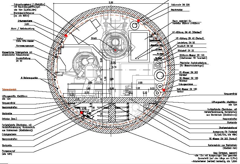
2 TTF EMI/EMC Working Group Meeting 29/05/2006 H. Kapitza (FLA) XFEL Tunnel Grounding (2) Topics: 1. Cross Section Update 2. Floor Inclusion 3. Mockup Tunnel 4. Next Steps
3 XFEL Facility Ground Due to its length >> λ(2 MHz)/10 = 15 m the XFEL facility needs a hybrid ground system where many local single-point grounding areas are connected to a common facility ground. In order to push its impedance as low as possible, the common facility ground (plane) should include as much through-going metal structure as possible (tubes, pipes, cable trays, remesh,...). Since these components will not really form a plane, aim at a mesh size λ(2 MHz)/50 = 3 m.
4

5 Röntgenlaser XFEL Tunnelquerschnitt Modulstrecke Bauliche Planung
6 Vorschlag fuer XTL Bodenplatten T. Hott, 22 Mai 06 Fahrweg Installationsseite Gitter (alle m) - 3t belastbar Kantenschutz Gewindeloch - M6 oder M8
7 XFEL Mockup Tunnel On May 3, 2006 there was a meeting of all parties interested in an XFEL mockup tunnel. Originally I expressed interest in operating a klystron there, fired by a stretched out pulse cable. During the meeting the following became clear: Most parties are interested in logistics checks, with access as freely as possible. Klystron operation will hinder this substantially. The mockup will be rather small, like 30 m long or so. For usage and cost reasons that makes sense. But this is not the place to test stretched out pulse cables. There are better test scenarios for the pulse cables. Currently no EMC use of XFEL mockup tunnel.
8 Next Steps For the following points some understanding and some numbers are still missing. They will be presented next time: 1. Energy radiated from the pulse cables and its absorption by the tunnel mesh. 2. Pulse cable cutoff frequencies and consequences for the cable trays.
9 Umbau TTF2 Injector Rack Area A third hut for the synchronisation laser will be set up (end of July). The rack area will be partly rearranged and enclosed. At the same time an adequate ground plane will be prepared. Its current state is desolate. The power supply situation must be inspected and probably revised (power from two HVen). Meeting with J.Schäfer (MKK) on At the same time remove old TTF1 ground system relics.
10
11

12 EMI shielding for the new Injectorlaser

13 EMI shielding for the new Injectorlaser Right now no special shielding agains EMI, all cable connections are routed through two holes in the wall.


14 EMI shielding for the new Injectorlaser Also the cable connections in the laser hut are not routed ideal to minimize crosstalk


15 Current problems- from outside 230V Mains Current on compresse air

16 Current problems- from outside 230V Mains Current on network cable
17 Current problems- from outside Laser oscillator during maintenance day Laser oscillator during normal run Suspect: Modulator/Klystron
18 Current problems- from inside Pockelscell driver Kabel tray
 are visible -")
19 Current problems- from inside PTO direct from photodiode via RG58 Output from ontable LEMO cable, not connected to the photodiode The pockelscell outpus pulses (~4 kv) are visible - crosstalk


20 Shielding - floor Old hut New hut

21 Shielding walls, roof

22 Cable connections routing through wall
23 Cable connections Ethernet Old scheme: Standard twisped pair connection from the switch in the injector area to every device New proposal: One fiber link from the old control room in the laser, a switch "satellite" in the laser hut. But the satellite offers 24 ports, overkill? contact person: Thorsten Witt, Is it possible to use this satellite for both huts? Alternative: Media converters to get fiber links from the Injctor area. Timing Old: New proposal: Fiber optic connection into the hut, timing distribution in the laser hut. RF Old scheme: RF-Cables from the master into the laser hut. New proposal: RF-Cables decoupled by a DC-block into the hut. BIS (temperatures, (door-)interlocks Old scheme: Cables from the devices to the BIS-box in the hut New proposal:
24 Cable connections Motor-Control Old scheme: CAN-Bus controller in the injector area, cables to each motor. New proposal: Beckhoff controller box in the laser-hut. Connected via ethernet. Problems with different hardware in old/new laser? Distance measurement Old scheme: Pick-up connected by cable to the measurement transceiver in the injector area. New proposals: Not urgend needed, to be planned but not connected. Is there a possibility to put a filter in the cable connection? Mains Old scheme: Standard connection New proposal: Use a line filter or transformer. BIC Old scheme: Ground free differential signal, opto coupled inputs New proposal: -


25 Does this effort make sense? The hut is not designed as EMI shield
26 Some links Company for cable connections (Hamburg): Some considerations can be found in the logbook:
27 EMI Sources and Noise in the Laser Hut Efforts in the injector rack area must be coordinated with efforts in the nearby laser hut. Just as the injector rack area, the laser hut has a complete safety ground system but no low impedance high frequency instrumentation ground system. Significant EMI currents were measured on interconnecting 27 MHz reference cables. Add a low impedance instrumentation ground system to this area: Lay down a cm wide, 0.4 mm thick copper conductor under the racks and under the optical table which are then low impedance connected to it. Signal cables should be routed close to this ground plane (which includes the table). The same is true for existing safety ground conductors which should/must be kept.
28 Near the power entrance to the hut the instrumentation ground should connect to an external reference, e.g. the injector rack area ground plane. Cables exiting the hut or connecting to other ground systems or longer than λ/10 should be fitted with DC blocks. Some power supply considerations: If possible use the same main power source for the injector racks and the laser hut with a common safety ground point. Separate power for EMI sources, e.g. flash lamp drivers, and instrumentation racks. Provide rack power filters as proposed for the injector rack area.
Detailed Design Report
 Detailed Design Report Chapter 4 MAX IV Injector 4.6. Acceleration MAX IV Facility CHAPTER 4.6. ACCELERATION 1(10) 4.6. Acceleration 4.6. Acceleration...2 4.6.1. RF Units... 2 4.6.2. Accelerator Units...
XFEL High Power RF System Recent Developments
 XFEL High Power RF System Recent Developments for the XFEL RF Group Outline XFEL RF System Requirements Overview Basic Layout RF System Main Components Multibeam Klystrons Modulator RF Waveguide Distribution
OPERATOR MANUAL OSD390 SERIES 4 CHANNEL VIDEO/AUDIO/DATA FIBER OPTIC TRANSMISSION SYSTEM
 PTY. LTD A.B.N. 83 003 020 504 OPERATOR MANUAL OSD390 SERIES 4 CHANNEL VIDEO/AUDIO/DATA FIBER OPTIC TRANSMISSION SYSTEM OSD390 SERIES 4 CHANNEL VIDEO/AUDIO/DATA FIBER OPTIC TRANSMISSION SYSTEM Document
Open Rack Specification 2.1 Update
 Rack and Power Open Rack Specification 2.1 Update Steve Mills Technical Lead Facebook Busbar Thickness Tolerance Reduction Reduce Rack Frame Tolerance Agenda Add Appendix D: Optional Rack-level EMI test
SINAMICS G130. dv/dt filter plus Voltage Peak Limiter. Operating Instructions 03/2013 SINAMICS
 SINAMICS G130 Operating Instructions 03/2013 SINAMICS s dv/dt filter plus Voltage Peak Limiter Safety information 1 General 2 SINAMICS SINAMICS G130 Operating Instructions Mechanical installation 3 Electrical
Vocia VI-6. Operation Manual
 Vocia VI-6 Operation Manual Biamp Systems 9300 S.W. Gemini Drive, Beaverton, Oregon 97008 U.S.A. (503) 641-7287 www.biamp.com table of contents vocia INPUT 6 (vi-6) features..............................................................
3 cerl. 3-1 cerl Overview. 3-2 High-brightness DC Photocathode Gun and Gun Test Beamline
 3 cerl 3-1 cerl Overview As described before, the aim of the cerl in the R&D program includes the development of critical components for the ERL, as well as the construction of a test accelerator. The
SECTION 7 -- CROSS-CONNECT SYSTEMS
 DETAIL ENGINEERING REQUIREMENTS AT&T March, 2016 Section 7, ATT-TP-76400 Revised NA SECTION 7 -- CROSS-CONNECT SYSTEMS CONTENTS PAGE 1. GENERAL... 7-2 1.1. Introduction... 7-2 1.2. Cable Holes... 7-2 1.3.
5 Project Costs and Schedule
 93 5 Project Costs and Schedule 5.1 Overview The cost evaluation for the integrated version of the XFEL with 30 experiments and 35 GeV beam energy as described in the TDR-2001 yielded 673 million EUR for
The FLASH objective: SASE between 60 and 13 nm
 Injector beam control studies winter 2006/07 talk from E. Vogel on work performed by W. Cichalewski, C. Gerth, W. Jalmuzna,W. Koprek, F. Löhl, D. Noelle, P. Pucyk, H. Schlarb, T. Traber, E. Vogel, FLASH
Effective earthing of screened cables
 NOVEMBER 2006 Effective earthing of screened cables All metallic containment items, other extraneous metalwork and the screens of telecommunications cables in an information technology environment must
UNIVERSITY of NORTH DAKOTA LOW VOLTAGE COMMUNICATIONS STANDARDS FOR CABLING, PATHWAYS, AND SPACE
 UNIVERSITY of NORTH DAKOTA LOW VOLTAGE COMMUNICATIONS STANDARDS FOR CABLING, PATHWAYS, AND SPACE Prepared in cooperation and approval from BICSI Building Industry Consulting Services International and
14 GHz, 2.2 kw KLYSTRON GENERATOR GKP 22KP 14GHz WR62 3x400V
 14 GHz, 2.2 kw KLYSTRON GENERATOR GKP 22KP 14GHz WR62 3x400V With its characteristics of power stability independent of the load, very fast response time when pulsed (via external modulated signal), low
PEP-II Overview & Ramp Down Plan. J. Seeman DOE PEP-II Ramp Down-D&D Review August 6-7, 2007
 PEP-II Overview & Ramp Down Plan J. Seeman DOE PEP-II Ramp Down-D&D Review August 6-7, 2007 Topics Overview of the PEP-II Collider PEP-II turns off September 30, 2008. General list of components and buildings
LCLS RF Reference and Control R. Akre Last Update Sector 0 RF and Timing Systems
 LCLS RF Reference and Control R. Akre Last Update 5-19-04 Sector 0 RF and Timing Systems The reference system for the RF and timing starts at the 476MHz Master Oscillator, figure 1. Figure 1. Front end
Emcore SITU2831 Externally Modulated RF Amplified Fiber Optic Transmitter and SIRU3000 Fiber Optic Receiver
 PRELIMINARY Applications RF and microwave antenna signal distribution EW Systems Broadband delay-line and signal processing systems Frequency distribution systems Radar system calibration Phased array
INSTALLATION MANUAL. CT-DUC-DDC Digital Off-Air Up Converter and Down Converter
 INSTALLATION MANUAL CT-DUC-DDC Digital Off-Air Up Converter and Down Converter 1 PACKAGE CONTENTS This package contains: One CT-DUC Digital Off-Air Up Converter One CT-DDC Digital Off-Air Down Converter
DPD80 Visible Datasheet
 Data Sheet v1.3 Datasheet Resolved Inc. www.resolvedinstruments.com info@resolvedinstruments.com 217 Resolved Inc. All rights reserved. General Description The DPD8 is a low noise digital photodetector
Installation. SAPTF33xx-1xx in the Network. Standard Configuration
 SAPTF33xx-1xx in the Network Standard Configuration One Unit A device (SAPTF33xx-100) and one device () are required for the standard configuration. The Unit A device is connected to the while the device
OPTICA TECHNOLOGIES INCORPORATED and the OPTICA TECHNOLOGIES INCORPORATED logo are trademarks of Optica Technologies Incorporated.
 Optica Technologies Incorporated 34600 FXBT Converter Quick Start Guide Product Warranty Safety Warnings 34600/070208 Trademarks OPTICA TECHNOLOGIES INCORPORATED and the OPTICA TECHNOLOGIES INCORPORATED
National Park Service Photo. Utah 400 Series 1. Digital Routing Switcher.
 National Park Service Photo Utah 400 Series 1 Digital Routing Switcher Utah Scientific has been involved in the design and manufacture of routing switchers for audio and video signals for over thirty years.
E3/DS3 Fibre Extender
 User Manual E3/DS3 Fibre Extender Black Box Network Services 464 Basingstoke Road, Reading, Berkshire, RG2 0BG Tech: 0118 965 6000 www.blackbox.co.uk CONTENTS 1 Introduction 1 1.1 About the products 1
SignalOn Series. L-Band Power Inserter Module INSTALLATION & OPERATION MANUAL. 1.2 GHz. D3.
 SignalOn Series D3.1/CCAP Compliant 1.2 GHz L-Band Power Inserter Module INSTALLATION & OPERATION MANUAL www.atxnetworks.com www.atxnetworks.com Although every effort has been taken to ensure the accuracy
DPD80 Infrared Datasheet
 Data Sheet v1.4 DPD8 Infrared DPD8 Infrared Datasheet Resolved Inc. www.resolvedinstruments.com info@resolvedinstruments.com 217 Resolved Inc. All rights reserved. DPD8 Infrared General Description The
Application Note AN-LD09 Rev. B Troubleshooting Low Noise Systems. April, 2015 Page 1 NOISE MEASUREMENT SYSTEM BASELINES INTRODUCTION
 Troubleshooting Low Noise Systems April, 2015 Page 1 INTRODUCTION The exceedingly low level of electronic noise produced by the QCL family of drivers makes narrower linewidths and stable center wavelengths
ACTIVE IF SPLITTER/COMBINER UHP-IFS
 ACTIVE IF SPLITTER/COMBINER UHP-IFS GENERAL DESCRIPTION AND INSTALLATION GUIDE DOCUMENT RELEASE 2 [UHP.IFS.2.EN] JUNE 2016 CONTENT Acronyms and Abbreviations... 4 Introduction... 5 Required level of qualification...
Digital Video Engineering Professional Certification Competencies
 Digital Video Engineering Professional Certification Competencies I. Engineering Management and Professionalism A. Demonstrate effective problem solving techniques B. Describe processes for ensuring realistic
LONWORKS Fibre Optic Converter
 LONWORKS Fiber Optic Converter LRW-102 and LRW-102/PP LONWORKS to fibre optic link, multidrop and redundant ring applications The LRW-102 is a fibre optic modem designed for multidrop and redundant ring
Fiber Optic Splice Closure GPJ Instruction Manual
 Fiber Optic Splice Closure GPJ09-9401 Instruction Manual 1. Brief Introduction GPJ09-9401 type of Fiber Optic Splice Closure is a member in dome series, the main function is to provice direct pass, branch
LONWORKS Fibre Optic Router
 LONWORKS Fiber Optic Router LRW-112 and LRW-112/PP LONWORKS to fibre optic link, multidrop and redundant ring applications The LRW-112 router offers an easy way to extend the distance between LONWORKS
Effects of the cryogenics operational conditions on the mechanical stability of the FLASH linac modules
 Effects of the cryogenics operational conditions on the mechanical stability of the FLASH linac modules Ramila Amirikas, Alessandro Bertolini, Jürgen Eschke, Mark Lomperski XFEL Module Meeting, January
18 GHz, 2.2 kw KLYSTRON GENERATOR GKP 24KP 18GHz WR62 3x400V
 18 GHz, 2.2 kw KLYSTRON GENERATOR GKP 24KP 18GHz WR62 3x400V With its characteristics of power stability whatever the load, very fast response time when pulsed (via external modulated signal), low ripple,
ELECTRICAL SAFETY INSPECTION REPORT. MTM Garments Ltd.
 ELECTRICAL SAFETY INSPECTION REPORT MTM Garments Ltd. 15934/16004, Chanpara, Medical Road, Uttarkhan, Dhaka, Bangladesh. Factory List MTM Garments Ltd. Inspected by: Hemlal Dahal Report Generated by: Hemlal
DVBus and Multiplexer and demultiplexer assemblies for video channels, with bidirectional audio and data USER MANUAL
 DVBus 8350-16 and 8350-4 Multiplexer and demultiplexer assemblies for 16-4 video channels, with bidirectional audio and data USER MANUAL 1. Description. Indicators and system connections DVBus 8350 systems
Current status of XFEL/SPring-8 project and SCSS test accelerator
 Current status of XFEL/SPring-8 project and SCSS test accelerator Takahiro Inagaki for XFEL project in SPring-8 inagaki@spring8.or.jp Outline (1) Introduction (2) Key technology for compactness (3) Key
Introduction to Fiber Optic Cable Technology Jerry Bednarczyk, PE Course Content
 Introduction to Fiber Optic Cable Technology Jerry Bednarczyk, PE Course Content Page 1 of 10 GENERAL A fiber optic cable system is very similar to a copper wire system in that it is used to transmit data
TTF / VUV-FEL. Schedule 2005 and Project Management Issues. Schedule 2005 Project Organisation Budget & Controlling
 TTF / VUV-FEL Schedule 200 and Project Management Issues Schedule 200 Project Organisation Budget & Controlling Hans Weise / DESY DESY MAC Meeting November 9th, 2004 TTF Linac Start-up After Final Installation
Ethernet Media Converters
 Allied Telesyn AT-MC13, AT-MC14, AT-MC15 and AT-MC16 Media Converters Seite 1 von 5 AT-MC13 Media Converter UTP to Fiber "ST" AT-MC14 Media Converter UTP to Fiber "SC" AT-MC15 Media Converter UTP to BNC
DA MHz Series of Narrowband or Wideband Distribution Amplifiers
 DA1-100-10-10MHz Series of Narrowband or Wideband Distribution Amplifiers Key Features 1-10 MHz wideband Operation. Other band frequencies from 100 khz to 200 MHz are available AGC Level Controlled. Output
ANKA RF System - Upgrade Strategies
 ANKA RF System - Upgrade Strategies Vitali Judin ANKA Synchrotron Radiation Facility 2014-09 - 17 KIT University of the State Baden-Wuerttemberg and National Laboratory of the Helmholtz Association www.kit.edu
Building + Mounting Learn Rooftop Basics
 Building + Mounting Learn Rooftop Basics A Build-It-Ourselves Guide to Wireless Mesh Networks 1 Introduction This module provides helpful tips for installing wireless equipment on rooftops. It should be
opengear OPG-1L 50 MHz-2.3 GHz
 MODEL opengear OPG-1L 50 MHz-2.3 GHz RF FIBER OPTIC LINK EMCORE s opengear OPG-1L s are optimized to perform in the 50 MHz to 2.3 GHz frequency range providing transparent signal transport for satellite
DA : Series of Narrowband or Wideband Distribution Amplifiers
 DA1-100-10: Series of Narrowband or Wideband Distribution Amplifiers Key Features 1-100 MHz wideband Operation. Other band frequencies from 100 khz to 200 MHz are available AGC Level Controlled. Output
LLRF at SSRF. Yubin Zhao
 LLRF at SSRF Yubin Zhao 2017.10.16 contents SSRF RF operation status Proton therapy LLRF Third harmonic cavity LLRF Three LINAC LLRF Hard X FEL LLRF (future project ) Trip statistics of RF system Trip
Fibre optic router for TP/FT-10 LRW-112PP
 Fibre optic router for TP/FT-10 LRW-112PP Lo n Wo r k s to fibre optic link, point-to-point applications The LRW-112PP router offers an easy way to extend the distance between LONWORKS 78 kbit/s TP/FT
Next Linear Collider. The 8-Pack Project. 8-Pack Project. Four 50 MW XL4 X-band klystrons installed on the 8-Pack
 The Four 50 MW XL4 X-band klystrons installed on the 8-Pack The Demonstrate an NLC power source Two Phases: 8-Pack Phase-1 (current): Multi-moded SLED II power compression Produce NLC baseline power: 475
HDMI Technology. HDMI Over Category 6 HDBaseT Signal Extenders
 Product Bulletin PB 494 Belden HDMI Connectivity Solutions Belden now offers a complete solution for sending HDMI signals over long distances without a reduction in signal quality. Whether using Category
AN-990 Radiated Emissions and CRT Displays
 AN-990 Radiated Emissions and CRT Displays Literature Number: SNOA347 Radiated Emissions and CRT Displays INTRODUCTION Electromagnetic compatibility (EMC) is a vital concern for anyone who produces or
Minimum qualifications for the Telecommunications Engineer are: A. Texas Licensed Profession Engineer (PE)
") PART 1: GENERAL 1.01 Telecommunications Engineer Minimum qualifications for the Telecommunications Engineer are: A. Texas Licensed Profession Engineer (PE) B. Registered Communications Distribution Designer
PART 1: GENERAL 1.01 Telecommunications Engineer Minimum qualifications for the Telecommunications Engineer are: A. Texas Licensed Profession Engineer (PE) B. Registered Communications Distribution Designer
Preventing Fieldbus Physical Layer Problems
 Preventing Fieldbus Physical Layer Problems 1 Introduction Foundation Fieldbus is highly reliable when correctly installed and maintained. The key is in knowing what must be done to start with and to maintain
Siemens Industry Online Support
 SINAMICS G120 (CU240x DP): What are the possible causes of F0070 at G120, and how do I avoid them? CU240S DP, CU240D DP FAQ November/2013 Siemens Industry Online Support Answers for industry. Table of
Spec Sheet. InterReach Fusion Wideband 2.5 GHz WiMAX. In-Building Wireless Networking System. Product Highlights
 In-Building Wireless Networking System InterReach Fusion is the latest addition to ADC s portfolio of Distributed Antenna Systems. It offers the same superior performance as Unison in an easy-to-install,
Bravo AV s Structured or Whole-House Wiring Approach
 Custom Audio & Video Systems: Design and Installation Bravo AV s Structured or Whole-House Wiring Approach THE QUALITY OF THE CABLE YOU USE IS CRITICALLY IMPORT TO THE PERFORMANCE OF YOUR SYSTEM Introduction
5100 Series IF Fiber Optic Links
 The 51Series fiberoptic interfacility links (IFLs) are a high performance, costeffective alternative to coaxial cable for 1 MHz to 2 MHz IF \satellite communications applications. Emcore s fiberoptic IFLs,
INSTALLATION MANUAL. CTMS-516RKPS Rack Mount Satellite Multiswitch
 INSTALLATION MANUAL CTMS-516RKPS Rack Mount Satellite Multiswitch 1 PACKAGE CONTENTS This package contains: One CTMS-516RKPS Rack Mount Satellite Multiswitch One CTMS-516RKPS Installation Manual PRODUCT
Summary of recent photocathode studies
 Summary of recent photocathode studies S. Lederer, S. Schreiber DESY L. Monaco, D. Sertore INFN Milano LASA FLASH seminar November 17 th, 2009 Outlook Cs 2 Te photocathodes Pulsed QE measurements laser
Traditional RF Splitter/Combiner and Directional Coupler User Manual
 Traditional RF Splitter/Combiner and Directional Coupler User Manual Content Page INTRODUCTION... 1 Revision History... 2 Trademark Information... 2 Admonishments... 2 General Safety Precaution... 2 1
Digital BPMs and Orbit Feedback Systems
 Digital BPMs and Orbit Feedback Systems, M. Böge, M. Dehler, B. Keil, P. Pollet, V. Schlott Outline stability requirements at SLS storage ring digital beam position monitors (DBPM) SLS global fast orbit
Traditional RF Splitter/Combiner and Directional Coupler User Manual
 Traditional RF Splitter/Combiner and Directional Coupler User Manual Content Page INTRODUCTION... 1 Revision History... 2 Trademark Information... 2 Admonishments... 2 General Safety Precaution... 2 1
Installation Overview
 Installation Overview Overview This chapter presents cable preparation and installation procedures for coaxial cables. Many connectors and special-purpose installation tools required for these cables are
EPON ONU Triplexer Transceiver
 EPON ONU Triplexer Transceiver Features Single Fiber Triplexer 1.25Gbps data upstream and downstream /45~1000MHz CATV analog signal downstream Burst mode transmission with 1310nm FP laser Continuous mode
PHOTOTUBE SCANNING SETUP AT THE UNIVERSITY OF MARYLAND. Doug Roberts U of Maryland, College Park
 PHOTOTUBE SCANNING SETUP AT THE UNIVERSITY OF MARYLAND Doug Roberts U of Maryland, College Park Overview We have developed a system for measuring and scanning phototubes for the FDIRC Based primarily on
w w w. e m c t e s t. i t
 GTEM EMC 1000 - INOX Frequency Range: 100KHz to 20GHz Max. Power-Input: 1000 W Input Connector Type: N (Female) Nominal Impedance: 50 Ω Typical VSWR: 1:1.2 Power Line Filter: 2x 230V AC/DC 16A RF Coax
AT&T January, 2012 Revised December, 2018 TABLE OF CONTENTS SECTION 1--INTRODUCTION...1-1
 SECTION 1--INTRODUCTION...1-1 1. General...1-1 1.1. Introduction...1-1 1.2. Purpose...1-2 1.3. Application...1-2 1.4. Definitions...1-3 1.5. General Requirements...1-3 1.6. Proprietary Information...1-5
Gigabit Multi-mode SX to Single Mode LX Converter. User s Manual NGF-728 Series. Warning COPYRIGHT
 COPYRIGHT Gigabit Multi-mode SX to Single Mode LX Converter User s Manual NGF-728 Series All rights reserved. No part of this publication may be reproduced, stored in a retrieval system, or transmitted
INSTRUCTION MANUAL. FiberSaver Series, FS-6000, FS-12000, FS-18000
 INSTRUCTION MANUAL FiberSaver Series, FS-6000, FS-12000, FS-18000 SERIAL DIGITAL FIBER OPTIC TRANSPORT and DISTRIBUTION SYSTEM FOR SMPTE 259, 292, 424, DVB-ASI and other protocols 110 Newton Place Hauppauge,
Low-Energy Electron Linacs and Their Applications in Cargo Inspection
 Low-Energy Electron Linacs and Their Applications in Cargo Inspection Yawei Yang on behalf of Huaibi Chen *,1, Chuanxiang Tang 1 Yaohong Liu 2 *chenhb@tsinghua.edu.cn 1 Department of Engineering Physics,
L-Band Block Upconverter MKT-74 Rev B JULY 2017 Page 1 of 7
 Communications & Power Industries Product Description L-Band Block Upconverter (BUC) Introduction The basic architecture of a conventional satcom terminal is derived from the historical desire to keep
Product Operation Manual
 Product Operation Manual VL-FTX FORWARD TRANSMITTER MODULE Ver 1.1(Doc#01-02-008) VALE SYSTEMS INC. 10400 Overland Road #408 Boise, ID 83709-1449,USA Tel: 208.935.6317Fax: 208.935.6234 All rights reserved
PITZ Introduction to the Video System
 PITZ Introduction to the Video System Stefan Weiße DESY Zeuthen June 10, 2003 Agenda 1. Introduction to PITZ 2. Why a video system? 3. Schematic structure 4. Client/Server architecture 5. Hardware 6. Software
INFN School on Electron Accelerators. RF Power Sources and Distribution
 INFN School on Electron Accelerators 12-14 September 2007, INFN Sezione di Pisa Lecture 7b RF Power Sources and Distribution Carlo Pagani University of Milano INFN Milano-LASA & GDE The ILC Double Tunnel
Siemens Industry Online Support
 MICROMASTER (MM4): What are the possible causes of F0070 on MICROMASTER 4, and how do I avoid them? FAQ November 2013 Siemens Industry Online Support Answers for industry. Table of contents Table of contents
2 Work Package and Work Unit descriptions. 2.8 WP8: RF Systems (R. Ruber, Uppsala)
") 2 Work Package and Work Unit descriptions 2.8 WP8: RF Systems (R. Ruber, Uppsala) The RF systems work package (WP) addresses the design and development of the RF power generation, control and distribution
2 Work Package and Work Unit descriptions 2.8 WP8: RF Systems (R. Ruber, Uppsala) The RF systems work package (WP) addresses the design and development of the RF power generation, control and distribution
32 Channel CPCI Board User Manual
 0 Sections Page 1.0 Introduction 1 2.0 Unpacking and Inspection 1 3.0 Hardware Configuration 1 4.0 Board Installation 5 5.0 I/O Connections and the Front Panel 5 5.1 Front Panel Layout 5 5.2 Input and
Operating Manual (Edition 04/2004) sinamics. Line Reactors SINAMICS G130
 sinamics. Line Reactors SINAMICS G130") Operating Manual (Edition 04/2004) sinamics Line Reactors SINAMICS G130 Contents 1. Safety Information 2 2. General 5 3. Mechanical Installation 6 4. Electrical Installation 8 5. Technical Specifications
Operating Manual (Edition 04/2004) sinamics Line Reactors SINAMICS G130 Contents 1. Safety Information 2 2. General 5 3. Mechanical Installation 6 4. Electrical Installation 8 5. Technical Specifications
Full IEFC workshop Feb.
 How to keep the Injectors running for another 25 years S Baird (on behalf of EN/MEF/ABA) LHC Performance workshop Chamonix How does one keep a 50 51 year old running for another 25 years? accelerator How
Cellular Signal Booster
 Drive G-M Cellular Signal Booster THE ALUMINUM CASING OF YOUR SIGNAL BOOSTER!! WILL ADJUST TO THE TEMPERATURE OF ITS ENVIRONMENT, BUT IS DESIGNED TO PROTECT THE SIGNAL BOOSTER TECHNOLOGY. FOR EXAMPLE,
DEVELOPMENT OF WDM OPTICAL TRANSMISSION SYSTEM OVER GI-POF PAIR CABLE FOR TELEVISION RF, GIGABIT-ETHERNET, AND HDMI/DVI
 Proceedings of 23rd International Conference on Plastic Optical Fibers (ICPOF2014, Yokohama, Japan Oct.8-10,2014) DEVELOPMENT OF WDM OPTICAL TRANSMISSION SYSTEM OVER GI-POF PAIR CABLE FOR TELEVISION RF,
L-BAND FREQUENCY CONVERTER
 SPACE L-BAND FREQUENCY CONVERTER Satellite communications, earth observation, navigation and positioning and control stations indracompany.com L-BAND CONVERTER L-BAND FREQUENCY CONVERTER This high performance
High-end bi-directional aspect ratio converter with digital and analog outputs COPYRIGHT 2008 AXON DIGITAL DESIGN BV ALL RIGHTS RESERVED
 High-end bi-directional aspect ratio converter with digital and analog outputs A Synapse product COPYRIGHT 2008 AXON DIGITAL DESIGN BV ALL RIGHTS RESERVED NO PART OF THIS DOCUMENT MAY BE REPRODUCED IN
Linac 4 Instrumentation K.Hanke CERN
 Linac 4 Instrumentation K.Hanke CERN CERN Linac 4 PS2 (2016?) SPL (2015?) Linac4 (2012) Linac4 will first inject into the PSB and then can be the first element of a new LHC injector chain. It will increase
Review of Diamond SR RF Operation and Upgrades
 Review of Diamond SR RF Operation and Upgrades Morten Jensen on behalf of Diamond Storage Ring RF Group Agenda Stats X-ray and LN2 pressure results Cavity Failure Conditioning in the RFTF Cavity Simulations
O-to-E and E-to-O Converters
 O-to-E and E-to-O Converters Our line of Optical-to-Electrical and Electrical-to- Optical converters is ideal for bench research applications where low-cost, high-speed interface for a scope is desired.
More Precision. scancontrol // 2D/3D laser scanner (laser profile sensors)
") More Precision scancontrol // 2D/D laser scanner (laser profile sensors) 12 scancontrol 29x gapcontrol 29x1 Technical details and versions - z-axis measuring range up to 265mm - x-axis measuring range
More Precision scancontrol // 2D/D laser scanner (laser profile sensors) 12 scancontrol 29x gapcontrol 29x1 Technical details and versions - z-axis measuring range up to 265mm - x-axis measuring range
Operating instructions
 108183 2017-05-17 Page 1 0359 Operating instructions TPPL-EX series Hazardous environments luminaires Please read the instructions carefully before starting any works! Content: 1. Safety instructions 2.
MICROSENS. Fast Ethernet Switch Modul 4x 10/100Base-TX, 1x 100Base-FX. Description. Features
 Fast Ethernet Switch Modul 4x 10/100Base-TX, 1x 100Base-FX Description This Ethernet Switch Module has been designed with 4x10/100Base-TX ports and 1x100Base-FX fiber optic port for the interconnection
Front End Electronics
 CLAS12 Ring Imaging Cherenkov (RICH) Detector Mid-term Review Front End Electronics INFN - Ferrara Matteo Turisini 2015 October 13 th Overview Readout requirements Hardware design Electronics boards Integration
Status of the X-ray FEL control system at SPring-8
 Status of the X-ray FEL control system at SPring-8 T.Fukui 1, T.Hirono 2, N.Hosoda 1, M.Ishii 2, M.Kitamura 1 H.Maesaka 1,T.Masuda 2, T.Matsushita 2, T.Ohata 2, Y.Otake 1, K.Shirasawa 1,M.Takeuchi 2, R.Tanaka
THE EFFECT OF LOOSE CONNECTORS ON SHIELDING EFFECTIVENESS
 THE EFFECT OF LOOSE CONNECTORS ON SHIELDING EFFECTIVENESS Asheridge Communications (A Teleste PLC Company) has undertaken a study to further understand the issues of RFI (Radio Frequency Interference)
P P S - M W S C A N 1 H
 µ-controller-systems / HARD- & SOFTWARE-DESIGN POWER-SUPPLIES FROM MILLIWATTS TO KILOWATTS Device: PPS-MWS-3000-4500-CAN1H 06 / 2017 Page 1 / 6 S w i t c h i n g M o d e P o w e r S u p p l y f o r M a
INSTALLATION MANUAL FT-FOTR-1VDE-ST-S
 INSTALLATION MANUAL FT-FOTR-1VDE-ST-S 1-Channel Digital Duplex Baseband Video Transmitter and Receiver With Reverse Data Transmission & Ethernet Transmission v1.0 4/5/11 1 PACKAGE CONTENTS This package
ANSI C63.4 and CISPR 22-Harmony
 ANSI C63.4 and CISPR 22-Harmony at Last? Donald N. Heirman Lucent Technologies, Bell Laboratories Innovations Holmdel, New Jersey 07738 USA Abstract: This paper compares the most prevalent emission measurement
Photoinjector Laser Operation and Cathode Performance
 Photoinjector Laser Operation and Cathode Performance Daniele Sertore, INFN Milano LASA Siegfried Schreiber, DESY Laser operational experience Laser beam properties Cathode performances Outlook TTF and
NZQA unit standard version 3 Page 1 of 7. Demonstrate knowledge of telecommunications cable systems
 Page 1 of 7 Title Demonstrate knowledge of telecommunications cable systems Level 4 Credits 20 Purpose This unit standard covers underpinning knowledge necessary for technicians employed in installation
SPECIAL SPECIFICATION :1 Video (De) Mux with Data Channel
 Mux with Data Channel") 1993 Specifications CSJ 0924-06-223 SPECIAL SPECIFICATION 1160 8:1 Video (De) Mux with Data Channel 1. Description. This Item shall govern for furnishing and installing an 8 channel digital multiplexed
1993 Specifications CSJ 0924-06-223 SPECIAL SPECIFICATION 1160 8:1 Video (De) Mux with Data Channel 1. Description. This Item shall govern for furnishing and installing an 8 channel digital multiplexed
US-ILC Waveguide Industrialization Study. Marc Ross, Chris Nantista and Chris Adolphsen
 US-ILC Waveguide Industrialization Study Marc Ross, Chris Nantista and Chris Adolphsen ILC Local Power Distribution System (LPDS) variable power divider, pressurizable, 0-100%, phase stable pressure window
Drop Passives: Splitters, Couplers and Power Inserters
 ENGINEERING COMMITTEE Interface Practices Subcommittee AMERICAN NATIONAL STANDARD ANSI/SCTE 153 2016 Drop Passives: Splitters, Couplers and Power Inserters NOTICE The Society of Cable Telecommunications
XCOM1002JE (8602JE) Optical Receiver Manual
 Optical Receiver Manual") XCOM1002JE (8602JE) Optical Receiver Manual - 2 - 1. Product Summary XCOM1002JE (8602JE) outdoor optical receiver is our latest 1GHz optical receiver. With wide range receiving optical power, high output
XCOM1002JE (8602JE) Optical Receiver Manual - 2 - 1. Product Summary XCOM1002JE (8602JE) outdoor optical receiver is our latest 1GHz optical receiver. With wide range receiving optical power, high output
I/A Series Hardware Fiber Optic LAN Converter
 I/A Series Hardware PSS 21H-7F3 B4 The provides bidirectional conversion between coaxial and fiber optic media. The converter is compatible with existing I/A Series system hardware, utilizes industry standard
SRS and ERLP developments. Andrew moss
 SRS and ERLP developments Andrew moss Contents SRS Status Latest news Major faults Status Energy Recovery Linac Prototype Latest news Status of the RF system Status of the cryogenic system SRS Status Machine