CoLinkEx JTAG/SWD adapter USER MANUAL
|
|
|
- Suzan Murphy
- 6 years ago
- Views:
Transcription

1 CoLinkEx JTAG/SWD adapter USER MANUAL rev. A Website:
2 Contents Introduction Features of CoLinkEX adapter: Elements of CoLinkEx programmer LEDs description JTAG interface SW interface JTAG connector pins numbers CoLinkEX schematic How to supply target board from CoLinkEx Installation of CoLinkEx Install the Driver of CoLinkEx Connect CoLinkEx to PC Update the firmware Use CoLinkEX How to use CoLinkEx in CoIDE How to use CoLinkEx in CoFlash How to use CoLinkEx in MDK


 and Keil RealView MDK (with plugin) USB-B connector Support firmware upgrade via USB")

3 Introduction CoLinkEx is a hardware-debugging adapter, which supports SW debugging and supports ARM Cortex M devices, it supports debugging in CooCox software and Keil RealView MDK. Main features of LPC1343-HB module. In addition, ColinkEx can supply target board with 3.3V or 5V via JTAG connector 1. Features of CoLinkEX adapter: Support JTAG and SW interfaces for Cortex-M microcontrollers Supported in Coocox IDE (COIDE) and Keil RealView MDK (with plugin) USB-B connector Support firmware upgrade via USB Standard 20-pin JTAG connector Can supply target board with 3.3V or 5V via JTAG connector 4 LEDs for status of programmer Compact size 55х55х18mm 2. Elements of CoLinkEx programmer BUSY LED USB bootloader jumper, JP1 3V3 jumper for supply target board Connect LED ERROR LED USB connector PWR LED 3V3 voltage regulator 3V3 jumper for supply target board 3
4 2.1. LEDs description. CoLinkEx programmer have four LEDs for status indication PWR show status of programmer power supply Connect status of connection to USB BUSY this LED is ON if programmer in debug mode ERROR this LED is ON if any error is occur 3. JTAG interface CoLinkEx have a standard JTAG connector. The JTAG connector is a 20 way Insulation Displacement Connector (IDC) keyed box header (2.54mm male) that mates with IDC sockets mounted on a ribbon cable The following table lists the CoLinkEx JTAG pinout. Pin Signal TYPE Description 1 3V3 OUT Power 3V3 output for supply target board from voltage regulator of CoLinkEx. Voltage on this pin available, if 3V3 jumper is closed 2,3,11,17 NC - This pin is not connected in CoLinkEx JTAG data input of target CPU. It is recommended that this pin is pulled to a 5 TDI output defined state on the target board. Typically connected to TDI of the target CPU. JTAG mode set input of target CPU. This pin 7 TMS output should be pulled up on the target. Typically connected to TMS of the target CPU JTAG clock signal to target CPU. It is recommended that this pin is pulled to a 9 TCK output defined state of the target board. Typically connected to TCK of the target CPU 13 TDO Input JTAG data output from target CPU. Typically connected to TDO of the target CPU. 15 RESET output Target CPU reset signal. Typically connected to the RESET pin of the target CPU, which is typically called "nrst", "nreset" or "RESET". 19 5V OUT Power This pin can be used to supply power to the target hardware. Voltage on this pin available, if 3V3 jumper is closed 4,6,8,10,12,14,16 GND Ground These pins connected to GND in CoLinkEx. They should also be connected to GND in the target system 4

5 4. SW interface CoLinkEx JTAG connector is also compatible to ARM.s Serial Wire Debug (SWD). Pin Signal TYPE Description 1 3V3 OUT Power 3V3 output for supply target board from voltage regulator of CoLinkEx. Voltage on this pin available, if 3V3 jumper is closed 7 SWDIO Input/Output Single bi-directional data pin. A pull-up resistor is required. ARM recommends 100 kohms 9 SWCLK Output Clock signal to target CPU. It is recommended that this pin is pulled to a defined state on the target board. Typically connected to TCK of target CPU. 13 SWO Output Serial Wire Output trace port. (Optional, not required for SWD communication.) These pins connected to GND in CoLinkEx. 4,6,8,10,12,1 GND Ground They should also be connected to GND in the 4,16 target system 5. JTAG connector pins numbers Numbers of JTAG connector pins showed on photo below
6 6. CoLinkEX schematic 6
7 7. How to supply target board from CoLinkEx With CoLinkEx adapter, you can supply target board with 3.3V/400mA or 5V/400mA via JTAG connector. 3V3 jumper 5V jumper 7.1. Power supply with 3.3V For using this function, you must close 3V3 jumper. In this case, 3.3V from on-board voltage regulator will be connected to pin 1 of JTAG connector. On target board 3.3V power supply bus must be connected to pin 1 of JTAG connector Power supply with 5V For using this function, you must close 5V jumper. In this case, 5V from USB will be connected to pin 19 of JTAG connector. On target board, 5V power supply bus must be connected to pin 19 of JTAG connector. 7


8 8. Installation of CoLinkEx 8.1. Install the Driver of CoLinkEx You can download driver from Do the operations shown in the following picture 8
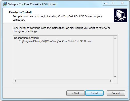
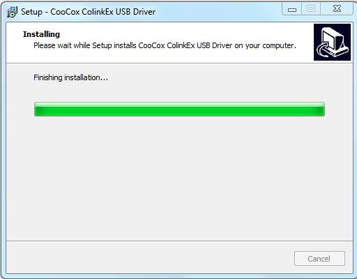
9 9
10 8.2. Connect CoLinkEx to PC When you connect CoLinkEx to PC, it will ask you to install the driver to system for the new detected devices. Then you may need to specify the path for CoLinkEx Driver. After you installed the driver, in the device manager, you will found CooCox(COM x)under Port and CooCox CoLinkEx Debug Interface under USB Controller. If there is a? in front of the two devices, it means that the driver have not been installed to the system or install failed; if there isn t CooCox Port, it means that your CoLinkEx firmware and driver is old version. 9. Update the firmware You can download firmware from How to update the firmware: 9.1. Short-circuit JP1 (activation of USB bootloader) 9.2. Connect CoLinkEx to the PC. Wait for the PC enumerates the removable disk whose label is "CRP2 ENABLD" or "CRP DISABLD". If it does not, you could press the reset button (BP1) for several times or power on again Delete the firmware.bin file in removable disk 9.4. Copy the downloaded firmware: ColinkEx_firmware_v0.4.bin into the removable disk 9.5. Disconnect JP1, power on again, then CoLinkEx will work normally 10
11 10. Use CoLinkEX Now CoLinkEx support CoIDE, CoFlash and CoMDKPlugin. The following is the configuration to use CoLinkEx in this software How to use CoLinkEx in CoIDE After create CoIDE Project, click Debug Configuration button 11


12 In debug configuration page, select CoLinkEx, and set other parameters In Download page, configure the flash algorithm 12

13 After compile the project, click the download button to Download code to Flash Click Debug button to debug the program. 13
, then select CoLinkEx in the adapter; modify the")

14 10.2. How to use CoLinkEx in CoFlash Open CoFlash, select a chip, e.g. (LPC11C14x301 from NXP), then select CoLinkEx in the adapter; modify the Port, Max Clock for the adapter if you need. You can refer to the following picture Switch to Download page to execute Download, Erase, Verify, Blank Check, etc 14


15 10.3. How to use CoLinkEx in MDK Before using CoLinkEx in Keil MDK you must install «CoLinkEx plugin for MDK» from Open MDK Project, Click Target options to configure the project Debug -> Use, open the configuration dialog and selects "CooCox Debugger". 15


16 Click "Settings", and then select the CoLinkEx as the adapter. You can also modify the Port, Max Clock for the adapter, Reset, Cache, Trace or Semihosting Options, etc. Switch to Flash Download to set the flash options and the flash algorithm. 16


17 Then, if you debug your program in flash, you also have to configure "Utilities" by selecting "CooCox Debugger" for Flash Programming Now you can use CoLinkEx to download and debug in MDK 17
Embest Emlink for ARM Cortex-M3. User Manual
 Embest Emlink for ARM Cortex-M3 User Manual (Getting Started) Version: 1.09.7.06 1/8 Emlink for ARM Cortex-M3 --- High Speed USB Adapter work with Keil RealView MDK & IAR EWARM 250KBytes/s Emlink for ARM
ST-LINK/V2 in-circuit debugger/programmer for STM8 and STM32
 User manual ST-LINK/V2 in-circuit debugger/programmer for STM8 and STM32 Introduction The ST-LINK/V2 is an in-circuit debugger/programmer for the STM8 and STM32 microcontroller families. The single wire
Connecting To and Programming the LPC2148 Blue Board. Method 1 ISP (In-System Programming) w/ Flash Magic
 w/ Flash Magic") Connecting To and Programming the LPC2148 Blue Board We have two primary methods of programming the LPC2148 Blue Board. We can use the supplied bootloader with ISP (In-System Programming) or JTAG (better
Connecting To and Programming the LPC2148 Blue Board We have two primary methods of programming the LPC2148 Blue Board. We can use the supplied bootloader with ISP (In-System Programming) or JTAG (better
MSP430 JTAG / BSL connectors
 MSP430 JTAG / BSL connectors (PD010A05 Rev-4: 23-Nov-2007) FAQ: Q: I have a board with the standard TI-JTAG pinhead. Can I use your programmer to flash my MSP430Fxx device? A: Yes. You can use any of our
ARM JTAG Interface Specifications
 ARM JTAG Interface Specifications TRACE32 Online Help TRACE32 Directory TRACE32 Index TRACE32 Documents... ICD In-Circuit Debugger... Processor Architecture Manuals... ARM/CORTEX/XSCALE... ARM Application
JTAGcable II In Circuit Emulator for Atmel AVR microcontrollers. User s Guide REV 1.0. Many ideas one solution
 JTAGcable II In Circuit Emulator for Atmel AVR microcontrollers REV 1.0 User s Guide Evalu ation Board s for 51, AVR, ST, PIC microcontrollers Sta- rter Kits Embedded Web Serve rs Prototyping Boards Minimodules
Memec Spartan-II LC User s Guide
 Memec LC User s Guide July 21, 2003 Version 1.0 1 Table of Contents Overview... 4 LC Development Board... 4 LC Development Board Block Diagram... 6 Device... 6 Clock Generation... 7 User Interfaces...
SAU510-USB ISO PLUS v.2 JTAG Emulator. User s Guide 2013.
 User s Guide 2013. Revision 1.00 JUL 2013 Contents Contents...2 1. Introduction to...4 1.1 Overview of...4 1.2 Key Features of...4 1.3 Key Items of...5 2. Plugging...6 2.1. Equipment required...6 2.2.
DX-10 tm Digital Interface User s Guide
 DX-10 tm Digital Interface User s Guide GPIO Communications Revision B Copyright Component Engineering, All Rights Reserved Table of Contents Foreword... 2 Introduction... 3 What s in the Box... 3 What
Universal ByteBlaster
 Universal ByteBlaster Hardware Manual June 20, 2005 Revision 1.1 Amfeltec Corp. www.amfeltec.com Copyright 2008 Amfeltec Corp. 35 Fifefield dr. Maple, L6A 1J2 Contents Contents 1 About this Document...
SignalTap Plus System Analyzer
 SignalTap Plus System Analyzer June 2000, ver. 1 Data Sheet Features Simultaneous internal programmable logic device (PLD) and external (board-level) logic analysis 32-channel external logic analyzer 166
CHAPTER 3 EXPERIMENTAL SETUP
 CHAPTER 3 EXPERIMENTAL SETUP In this project, the experimental setup comprised of both hardware and software. Hardware components comprised of Altera Education Kit, capacitor and speaker. While software
Document Part Number: Copyright 2010, Corelis Inc.
 CORELIS Low Voltage Adapter Low Voltage Adapter Boundary-Scan Interface User s Manual Document Part Number: 70398 Copyright 2010, Corelis Inc. Corelis, Inc. 12607 Hiddencreek Way Cerritos, CA 90703-2146
Section 24. Programming and Diagnostics
 Section. and Diagnostics HIGHLIGHTS This section of the manual contains the following topics:.1 Introduction... -2.2 In-Circuit Serial... -2.3 Enhanced In-Circuit Serial... -5.4 JTAG Boundary Scan... -6.5
Tools to Debug Dead Boards
 Tools to Debug Dead Boards Hardware Prototype Bring-up Ryan Jones Senior Application Engineer Corelis 1 Boundary-Scan Without Boundaries click to start the show Webinar Outline What is a Dead Board? Prototype
Virtex-II Pro and VxWorks for Embedded Solutions. Systems Engineering Group
 Virtex-II Pro and VxWorks for Embedded Solutions Systems Engineering Group Embedded System Development Embedded Solutions Key components of Embedded systems development Integrated development environment
DSTREAM ARM. System and Interface Design Reference. Version 4.4. Copyright ARM. All rights reserved. ARM DUI 0499E (ID091611)
") ARM DSTREAM Version 4.4 System and Interface Design Reference Copyright 2010-2011 ARM. All rights reserved. ARM DUI 0499E () ARM DSTREAM System and Interface Design Reference Copyright 2010-2011 ARM. All
ARM DSTREAM Version 4.4 System and Interface Design Reference Copyright 2010-2011 ARM. All rights reserved. ARM DUI 0499E () ARM DSTREAM System and Interface Design Reference Copyright 2010-2011 ARM. All
Using the XC9500/XL/XV JTAG Boundary Scan Interface
 Application Note: XC95/XL/XV Family XAPP69 (v3.) December, 22 R Using the XC95/XL/XV JTAG Boundary Scan Interface Summary This application note explains the XC95 /XL/XV Boundary Scan interface and demonstrates
APPLICATION NOTE 4312 Getting Started with DeepCover Secure Microcontroller (MAXQ1850) EV KIT and the CrossWorks Compiler for the MAXQ30
 EV KIT and the CrossWorks Compiler for the MAXQ30") Maxim > Design Support > Technical Documents > Application Notes > Microcontrollers > APP 4312 Keywords: MAXQ1850, MAXQ1103, DS5250, DS5002, microcontroller, secure microcontroller, uc, DES, 3DES, RSA,
Maxim > Design Support > Technical Documents > Application Notes > Microcontrollers > APP 4312 Keywords: MAXQ1850, MAXQ1103, DS5250, DS5002, microcontroller, secure microcontroller, uc, DES, 3DES, RSA,
Debugging IDT S-RIO Gen2 Switches Using RapidFET JTAG
 Titl Debugging IDT S-RIO Gen2 Switches Using RapidFET JTAG Application Note March 29, 2012 About this Document This document discusses common problems that are encountered when debugging with a board that
Using the XSV Board Xchecker Interface
 Using the XSV Board Xchecker Interface May 1, 2001 (Version 1.0) Application Note by D. Vanden Bout Summary This application note shows how to configure the XC9510 CPLD on the XSV Board to enable the programming
Entry Level Tool II. Reference Manual. System Level Solutions, Inc. (USA) Murphy Avenue San Martin, CA (408) Version : 1.0.
 Murphy Avenue San Martin, CA (408) Version : 1.0.") Entry Level Tool II Reference Manual, Inc. (USA) 14100 Murphy Avenue San Martin, CA 95046 (408) 852-0067 http://www.slscorp.com Version : 1.0.3 Date : October 7, 2005 Copyright 2005-2006,, Inc. (SLS) All
Entry Level Tool II Reference Manual, Inc. (USA) 14100 Murphy Avenue San Martin, CA 95046 (408) 852-0067 http://www.slscorp.com Version : 1.0.3 Date : October 7, 2005 Copyright 2005-2006,, Inc. (SLS) All
MSP430-H2618 development board Users Manual
 MSP430-H2618 development board Users Manual All boards produced by Olimex are RoHS compliant Rev. Initial, April 2009 Copyright(c) 2009, OLIMEX Ltd, All rights reserved Page 1 INTRODUCTION: MSP430-H2618
Section 24. Programming and Diagnostics
 Section. Programming and Diagnostics HIGHLIGHTS This section of the manual contains the following topics:.1 Introduction... -2.2 In-Circuit Serial Programming... -3.3 Enhanced In-Circuit Serial Programming...
DMC550 Technical Reference
 DMC550 Technical Reference 2002 DSP Development Systems DMC550 Technical Reference 504815-0001 Rev. B September 2002 SPECTRUM DIGITAL, INC. 12502 Exchange Drive, Suite 440 Stafford, TX. 77477 Tel: 281.494.4505
STB Front Panel User s Guide
 S ET-TOP BOX FRONT PANEL USER S GUIDE 1. Introduction The Set-Top Box (STB) Front Panel has the following demonstration capabilities: Pressing 1 of the 8 capacitive sensing pads lights up that pad s corresponding
Raspberry Pi debugging with JTAG
 Arseny Kurnikov Aalto University December 13, 2013 Outline JTAG JTAG on RPi Linux kernel debugging JTAG Joint Test Action Group is a standard for a generic transport interface for integrated circuits.
Overview of BDM nc. The IEEE JTAG specification is also recommended reading for those unfamiliar with JTAG. 1.2 Overview of BDM Before the intr
 Application Note AN2387/D Rev. 0, 11/2002 MPC8xx Using BDM and JTAG Robert McEwan NCSD Applications East Kilbride, Scotland As the technical complexity of microprocessors has increased, so too has the
The user manual of LED display screen and RH-32G control card.
 The user manual of LED display screen and RH-32G control card. ⅠHardware parameters 1 The maximum number of points P10 solid color:32*768 32*256(2 pieces high and 24 pieces wide;2 pieces high and 8 pieces
Saving time & money with JTAG
 Saving time & money with JTAG AltiumLive 2017: ANNUAL PCB DESIGN SUMMIT Simon Payne CEO, XJTAG Ltd. Saving time and money with JTAG JTAG / IEEE 1149.X Take-away points Get JTAG right from the start Use
A Primer: ARM Trace. Including: ETM, ETB and Serial Wire Viewer, JTAG and SWD V 2.1
 A Primer: ARM Trace Including: ETM, ETB and Serial Wire Viewer, JTAG and SWD V 2.1 Agenda Introduction How we talk to your CPU using JTAG or SWD. Trace. ETM, ETB and SWV. How are they different? Triggers,
Ashling Product Brief APB219 v1.0.3, 12 th October 2018
 Ashling Product Brief APB219 v1.0.3, 12 th October 2018 Using Ultra-XD for Synopsys DesignWare ARC Cores with the MetaWare Debugger Contents 1. Introduction 2 2. Installation and Configuration 3 2.1 Installing
APPLICATION NOTE. Atmel AVR32850: ATSAM4L-EK User Guide. Atmel SAM4L. Features. Introduction
 APPLICATION NOTE Atmel AVR32850: ATSAM4L-EK User Guide Atmel SAM4L Features ATSAM4L-EK kit Board description Using the demonstration firmware Introduction The ATSAM4L-EK is a reference design and development
User Manual for ASSIST Evaluation & Programming Tool EPT002
 Page 1 of 60 User Manual for ASSIST Evaluation & Programming Tool EPT002 Page 2 of 60 CONTENTS 1. Hardware... 3 1.1 Contents... 3 1.2 Interface Board... 4 1.3 Target-Holder... 5 1.4 Targets: codewheels
XDS560R JTAG Emulator Technical Reference
 XDS560R JTAG Emulator Technical Reference 2006 DSP Development Systems XDS560R JTAG Emulator Installation Guide 507355-0001 Rev. B August 2006 SPECTRUM DIGITAL, INC. 120502 Exchange Drive, #440 Stafford,
Booya16 SDR Datasheet
 Booya16 SDR Radio Receiver Description The Booya16 SDR radio receiver samples RF signals at 16MHz with 14 bits and streams the sampled signal into PC memory continuously in real time. The Booya software
MSP430-HG2231 development board Users Manual
 MSP0-HG development board Users Manual All boards produced by Olimex are ROHS compliant Revision Initial, June 0 Copyright(c) 0, OLIMEX Ltd, All rights reserved Page INTRODUCTION: MSP0-HG is header board
How to overcome/avoid High Frequency Effects on Debug Interfaces Trace Port Design Guidelines
 How to overcome/avoid High Frequency Effects on Debug Interfaces Trace Port Design Guidelines An On-Chip Debugger/Analyzer (OCD) like isystem s ic5000 (Figure 1) acts as a link to the target hardware by
Instruction manual Universal Fieldbus-Gateway UNIGATE IC - RS
 Instruction manual niversal Fieldbus-Gateway NIGE IC - S rt.-no.: V3504E Carl-Zeiss-Str. 8 D-65520 Bad Camberg el:+49-(0)6434-9433-0 Hotline: +49-(0)6434-9433-33 Fax: +49-(0)6434-9433-40 Internet: http://www.deutschmann.de
Image generator. Hardware Specification
 Image generator [SVO-03] Rev. NetVision Co., Ltd. Update History Revision Date Note 2018/07/02 New File(Equivalent to Japanese version 1.2) S.Usuba i index 1. Outline... 1 1.1. features and specification
SXGA096 DESIGN REFERENCE BOARD
 SXGA096 DESIGN REFERENCE BOARD For Use with all emagin SXGA096 OLED Microdisplays USER S MANUAL VERSION 1.0 TABLE OF CONTENTS D01-501152-01 SXGA096 Design Reference Board User s Manual i 1. INTRODUCTION...
VNS2200 Amplifier & Controller Installation Guide
 VNS2200 Amplifier & Controller Installation Guide VNS2200 Amplifier & Controller Installation 1. Determine the installation location for the VNS2200 device. Consider the following when determining the
VNS2210 Amplifier & Controller Installation Guide
 VNS2210 Amplifier & Controller Installation Guide VNS2210 Amplifier & Controller Installation 1. Determine the installation location for the VNS2210 device. Consider the following when determining the
IOCard Displays II Manual. Date:08/03/17 Rev.:2.3
 Date:08/03/17 Rev.:2.3 Index: IOCARD DISPLAYS II MANUAL... 1 INDEX:... 2 INTRODUCTION:... 3 DISPLAYS II:... 3 Components and outline:... 3 Connector's description:... 4 INPUTS:... 4 Displays direct to
Manual Version Ver 1.0
 The BG-3 & The BG-7 Multiple Test Pattern Generator with Field Programmable ID Option Manual Version Ver 1.0 BURST ELECTRONICS INC CORRALES, NM 87048 USA (505) 898-1455 VOICE (505) 890-8926 Tech Support
University Program Design Laboratory Package
 University Program Design Laboratory Package November 1999, ver. 1.02 User Guide Introduction The University Program Design Laboratory Package was designed to meet the needs of universities teaching digital
SWITCH: Microcontroller Touch-switch Design & Test (Part 2)
") SWITCH: Microcontroller Touch-switch Design & Test (Part 2) 2 nd Year Electronics Lab IMPERIAL COLLEGE LONDON v2.09 Table of Contents Equipment... 2 Aims... 2 Objectives... 2 Recommended Timetable... 2
SWITCH: Microcontroller Touch-switch Design & Test (Part 2) 2 nd Year Electronics Lab IMPERIAL COLLEGE LONDON v2.09 Table of Contents Equipment... 2 Aims... 2 Objectives... 2 Recommended Timetable... 2
The Haply Development Kit
 The Haply Development Kit Introduction The Haply development kit is a robust and adaptable open-source hardware development platform for haptic applications. Designed to be accessible to novices and experts
XJTAG DFT Assistant for
 XJTAG DFT Assistant for Installation and User Guide Version 1.0 enquiries@xjtag.com Table of Contents SECTION PAGE 1. Introduction...3 2. Installation...3 3. Quick Start Guide...3 4. User Guide...4 4.1.
3. Configuration and Testing
 3. Configuration and Testing C51003-1.4 IEEE Std. 1149.1 (JTAG) Boundary Scan Support All Cyclone devices provide JTAG BST circuitry that complies with the IEEE Std. 1149.1a-1990 specification. JTAG boundary-scan
University Program Design Laboratory Package
 University Program Design Laboratory Package October 2001, ver. 2.0 User Guide Introduction The University Program (UP) Design Laboratory Package was designed to meet the needs of universities teaching
JTAG ICE... User Guide
 JTAG ICE... User Guide Table of Contents Table of Contents Section 1 Introduction... 1-1 1.1 Features...1-1 1.2 JTAG ICE and the OCD Concept...1-2 1.2.4.1 Software Breakpoints...1-3 1.2.4.2 Hardware Breakpoints...1-3
AN1775 APPLICATION NOTE
 AN1775 APPLICATION NOTE STR71x HARDWARE DEVELOPMENT GETTING STARTED INTRODUCTION This application note is intended for system designers who require a hardware implementation overview of the development
Comparing JTAG, SPI, and I2C
 Comparing JTAG, SPI, and I2C Application by Russell Hanabusa 1. Introduction This paper discusses three popular serial buses: JTAG, SPI, and I2C. A typical electronic product today will have one or more
XDS510USB PLUS JTAG Emulator Technical Reference
 XDS510USB PLUS JTAG Emulator Technical Reference 2007 DSP Development Systems XDS510USB PLUS JTAG Emulator Installation Guide 509405-0001 Rev. A January 2007 SPECTRUM DIGITAL, INC. 120502 Exchange Drive,
uresearch GRAVITECH.US GRAVITECH GROUP Copyright 2007 MicroResearch GRAVITECH GROUP
 GRAVITECH.US uresearch GRAVITECH GROUP Description The I2C-7SEG board is a 5-pin CMOS device that provides 4-digit of 7-segment display using I 2 C bus. There are no external components required. Only
XJTAG DFT Assistant for
 XJTAG DFT Assistant for Installation and User Guide Version 2 enquiries@xjtag.com Table of Contents SECTION PAGE 1. Introduction...3 2. Installation...3 3. Quick Start Guide...3 4. User Guide...4 4.1.
University Program Design Laboratory Package
 University Program Design Laboratory Package August 1997, ver. 1 User Guide Introduction The University Program Design Laboratory Package was designed to meet the needs of universities teaching digital
C8188 C8000 1/10. digital audio modular processing system. 4 Channel AES/EBU I/O. features. block diagram. 4 balanced AES inputs
 features 4 balanced AES inputs Input Sample Rate Converters (SRC) 4 balanced AES outputs Relay bypass for pairs of I/Os Relay wait time after power up Master mode (clock master for the frame) 25pin Sub-D,
University of Arizona January 18, 2000 Joel Steinberg Rev. 1.6
 I/O Specification for Serial Receiver Daughter Board (PCB-0140-RCV) (Revised January 18, 2000) 1.0 Introduction The Serial Receiver Daughter Board accepts an 8b/10b encoded serial data stream, operating
Vorne Industries. 87/719 Analog Input Module User's Manual Industrial Drive Itasca, IL (630) Telefax (630)
 Telefax (630)") Vorne Industries 87/719 Analog Input Module User's Manual 1445 Industrial Drive Itasca, IL 60143-1849 (630) 875-3600 Telefax (630) 875-3609 . 3 Chapter 1 Introduction... 1.1 Accessing Wiring Connections
Vorne Industries 87/719 Analog Input Module User's Manual 1445 Industrial Drive Itasca, IL 60143-1849 (630) 875-3600 Telefax (630) 875-3609 . 3 Chapter 1 Introduction... 1.1 Accessing Wiring Connections
X-LINE Testing Device STB 01X. Manual.
 X-LINE Testing Device STB 01X. Manual. B-HB-040DE Manual X-LINE Testing Device STB 01X V 1.0 1 B-HB-040DE Manual X-LINE Testing Device STB 01X V 1.0 2 Table of Contents 1 General...4 2 Display and Key
USER'S MANUAL. Getting started with ALEXAN ATMEL AT89C2051/AT89C4051 Training Module - 1
 USER'S MANUAL Getting started with ALEXAN ATMEL AT89C05/AT89C405 Training Module - Version.0 Copyright 006 Ace Electronic Technology Inc. All Rights Reserved Alexan 05/405 TM- v..0 Page of 7 About This
EZCOM-1. PLC - to - AMS MESSAGE DISPLAY INTERFACE INSTALLATION AND OPERATING INSTRUCTIONS. Rev March, 2001
 EZCOM-1 PLC - to - AMS MESSAGE DISPLAY INTERFACE INSTALLATION AND OPERATING INSTRUCTIONS Rev 1.3 - March, 2001 CONTENTS Page INTRODUCTION 1 SPECIFICATIONS 1 LIST OF SUPPLIED ITEMS 1 INSTALLATION & TESTING
XJTAG DFT Assistant for
 XJTAG DFT Assistant for Installation and User Guide Version 2 enquiries@xjtag.com Table of Contents SECTION PAGE 1. Introduction...3 2. Installation...3 3. Quick Start Guide...3 4. User Guide...4 4.1.
Ten-Tec (865) Service Department:(865)
 Service Department:(865)") Ten-Tec (865) 453-7172 Service Department:(865) 428-0364 Installation Instructions for Ten-Tec Jupiter AT538K Tuner Kit The installation of the AT538K is divided into two steps. The first step is to reprogram
Ten-Tec (865) 453-7172 Service Department:(865) 428-0364 Installation Instructions for Ten-Tec Jupiter AT538K Tuner Kit The installation of the AT538K is divided into two steps. The first step is to reprogram
ATF15xx-DK3 Development Kit... User Guide
 ATF15xx-DK3 Development Kit... User Guide Table of Contents Section 1 Introduction... 1-1 1.1 CPLD Development/ Programmer Kit...1-1 1.2 Kit Contents...1-1 1.3 Kit Features...1-1 1.3.1 CPLD Development/Programmer
2070 PROFINET MODULE
 Kokkedal Industripark 4 DK-2980 Kokkedal Denmark info@eilersen.com Tel +45 49 180 100 Fax +45 49 180 200 2070 PROFINET MODULE Status and weight transfer using PROFINET Applies for: Software: CONCTR_4.160530.1v0
VHDL Upgrading of a TNT2 card
 VHDL Upgrading of a TNT2 card 1) Get some JTAG programming device... 1 2) Download the software to program Xilinx Component : IMPACT... 2 3) Virtex s 3 EEPROM s upgrade... 2 4) Spartan s EEPROM upgrade...
STEVAL-IFN003V1. DC PMSM FOC motor drive. Description. Features
 STEAL-IFN00 DC PMSM FOC motor drive Data brief Features STEAL-IFN00 Input range: 8 up to (up to 80 W) STMicroelectronic's AM TM Cortex-M corebased STMF0CBT microcontroller DMOS fully integrated three-phase
MIDI2DMX PRO. solid state MIDI to DMX converter. wwww.midi2dmx.eu
 MIDI2DM PRO solid state MIDI to DM converter wwww.midi2dmx.eu May 2011 From the authors Artistic and stage activity is like others aspects of our life - competition on the market is everywhere. On the
STEVAL-ICB004V1. Advanced resistive touchscreen controller demonstration board based on the STMPE811. Features. Description
 Advanced resistive touchscreen controller demonstration board based on the STMPE811 Data brief Features Four-wire resistive touch-sensing demonstration GUI Configurable touch-sensing parameters STMPE811
MACH3 LaserAce Installation Manual Revision 1. MACH3 LaserAce Installation Manual
 WWW.LASERARCADE.COM MACH3 LaserAce Installation Manual Revision 1 MACH3 LaserAce Installation Manual Table of Contents Introduction...1 Parts supplied with MACH3 FNI...1 Why the MACH3 FNI is required...2
Alice EduPad for Tiva or MSP432 TI ARM Launchpad. User s Guide Version /23/2017
 Alice EduPad for Tiva or MSP432 TI ARM Launchpad User s Guide Version 1.02 08/23/2017 1 Table OF Contents Chapter 1. Overview... 3 1.1 Welcome... 3 1.2 Tiva Launchpad features... 4 1.3 Alice EduPad hardware
MXS Strada USER GUIDE
 MXS Strada USER GUIDE AiM TECH Srl. Via Cavalcanti, 8 20063 Cernusco S/N (MI) Italia Tel. (+39) 02.9290571 Made in Italy www.aim-sportline.com MXS Strada 01. INTRODUCTION 02. WHAT IS IN THE KIT 03. LAYOUT
I N S T R U C T I O N D A T A
 I N S T R U C T I O N D A T A RFL (C37.94) Fiber Service Unit Single Mode 108015-1 RS-449 108015-2 V.35 108015-3 G.703 108015-4 X.21 108015-5 E1 Multimode 107460-1 RS-449 107460-2 V.35 107460-3 G.703 107460-4
XJTAG DFT Assistant for
 XJTAG DFT Assistant for Installation and User Guide Version 2 enquiries@xjtag.com Table of Contents SECTION PAGE 1. Introduction...3 2. Installation...3 3. Quick Start Guide...4 4. User Guide...4 4.1.
R4 AIS Class B Transponder
 Saab TransponderTech R4 AIS Class B Transponder Configuration Manual GENERAL Page 1 i Copyright The entire contents of this manual and its appendices, including any future updates and modifications, shall
Alice EduPad Board. User s Guide Version /11/2017
 Alice EduPad Board User s Guide Version 1.02 08/11/2017 1 Table OF Contents Chapter 1. Overview... 3 1.1 Welcome... 3 1.2 Launchpad features... 4 1.3 Alice EduPad hardware features... 4 Chapter 2. Software
REMOTE I/O R30 SERIES. PC CONFIGURATOR SOFTWARE Model: R30CFG Ver Users Manual
 REMOTE I/O R30 SERIES PC CONFIGURATOR SOFTWARE Model: R30CFG Ver. 1.13 Users Manual 5-2-55, Minamitsumori, Nishinari-ku, Osaka 557-0063 JAPAN Tel: +81-6-6659-8201 Fax: +81-6-6659-8510 http://www.m-system.co.jp/
Remote Diagnostics and Upgrades
 Remote Diagnostics and Upgrades Tim Pender -Eastman Kodak Company 10/03/03 About this Presentation Motivation for Remote Diagnostics Reduce Field Maintenance costs Product needed to support 100 JTAG chains
Using SignalTap II in the Quartus II Software
 White Paper Using SignalTap II in the Quartus II Software Introduction The SignalTap II embedded logic analyzer, available exclusively in the Altera Quartus II software version 2.1, helps reduce verification
Error connecting to the target: TMS320F28379D. 1 Error message on connecting the target.
 Error connecting to the target: TMS320F28379D 1 Error message on connecting the target. [Start: Texas Instruments XDS100v2 USB Debug Probe] Execute the command: %ccs_base%/common/uscif/dbgjtag -f %boarddatafile%
Configuring FLASHlogic Devices
 Configuring FLASHlogic s April 995, ver. Application Note 45 Introduction The Altera FLASHlogic family of programmable logic devices (PLDs) is based on CMOS technology with SRAM configuration elements.
BTW03 DESIGN CONSIDERATIONS IN USING AS A BACKPLANE TEST BUS International Test Conference. Pete Collins
 2003 International Test Conference DESIGN CONSIDERATIONS IN USING 1149.1 AS A BACKPLANE TEST BUS Pete Collins petec@jtag.co.uk JTAG TECHNOLOGIES BTW03 PURPOSE The purpose of this presentation is to discuss
Technical data. General specifications. Indicators/operating means
 Model Number Single head system Features Sensor head bidirectional and rotatable Function indicators visible from all directions Quick mounting bracket Selectable sound lobe width Programmable Diagrams
LED Array Board.
 LED Array Board www.matrixtsl.com EB087 Contents About This Document 2 General Information 3 Board Layout 4 Testing This Product 5 Circuit Description 6 Circuit Diagram 7 About This Document This document
RF4432 wireless transceiver module
 RF4432 wireless transceiver module 1. Description RF4432 adopts Silicon Lab Si4432 RF chip, which is a highly integrated wireless ISM band transceiver. The features of high sensitivity (-121 dbm), +20
F24X DSK Setup and Tutorial
 F24X DSK Setup and Tutorial 1999 DSP Development Systems F24X DSK Setup and Tutorial 504706-0001 Rev. A July 1999 SPECTRUM DIGITAL, INC. 10853 Rockley Road Houston, TX. 77099 Tel: 281.561.6952 Fax: 281.561.6037
W0EB/W2CTX DSP Audio Filter Operating Manual V1.12
 W0EB/W2CTX DSP Audio Filter Operating Manual V1.12 Manual and photographs Copyright W0EB/W2CTX, March 13, 2019. This document may be freely copied and distributed so long as no changes are made and the
Foreword: The purpose of this document is to describe how to install and configure Neets 4 relay box
 Foreword: The purpose of this document is to describe how to install and configure Neets 4 relay box COPYRIGHT All information contained in this manual is the intellectual property of and copyrighted material
BABAR IFR TDC Board (ITB): system design
: system design") BABAR IFR TDC Board (ITB): system design Version 1.1 12 december 1997 G. Crosetti, S. Minutoli, E. Robutti I.N.F.N. Genova 1. Introduction TDC readout of the IFR will be used during BABAR data taking to
BABAR IFR TDC Board (ITB): system design Version 1.1 12 december 1997 G. Crosetti, S. Minutoli, E. Robutti I.N.F.N. Genova 1. Introduction TDC readout of the IFR will be used during BABAR data taking to
How To Build Megavolt s Small Buffered JTAG v1.2
 How To Build Megavolt s Small Buffered JTAG v1.2 Abstract A JTAG cable should be considered mandatory equipment for any serious tester. It provides a means to backup the information in the receiver and
ARM HOW-TO GUIDE Interfacing Traffic Light with LPC2148
 ARM HOW-TO GUIDE Interfacing Traffic Light with LPC2148 Contents at a Glance ARM7 LPC2148 Primer Board... 3 Traffic Light Control... 3 About the colors of Traffic Light Control... 4 Interfacing Traffic
Spartan-IIE LC Development Board User s Guide
 Spartan-IIE LC Development Board User s Guide Version 1.0 March 2003 PN# DS-MANUAL-2SELC Memec Design Development Kit Owners Certificate Thank you for purchasing your Memec Design development kit. As an
C8000. sync interface. External sync auto format sensing : AES, Word Clock, Video Reference
 features Standard sync module for a frame Internal sync @ 44.1 / 48 / 88.2 / 96kHz External sync auto format sensing : AES, Word Clock, Video Reference Video Reference : Black Burst (NTSC or PAL) Composite
Step What to do Expected result What to do if test fails Component tested 1 Visual inspection. Board is accurately assembled
 Fox Delta Amateur Radio Projects & Kits AAZ-0914A 50MHZ Antenna Analyzer Testing Guide by Tony / I2TZK SWR Analyzer 4 steps for a quick test Step What to do Expected result What to do if test fails Component
Syntor X Flash Memory Module Revision C
 Syntor X Flash Memory Module Revision C The PIEXX SynXFlash memory module, along with the supplied PC software, replaces the original SyntorX code plugs and allows you to easily set modify and update your
RF4432F27 wireless transceiver module
 RF4432F27 wireless transceiver module 1. Description RF4432F27 is 500mW RF module embedded with amplifier and LNA circuit. High quality of component, tightened inspection and long term test make this module
Model 6010 Four Channel 20-Bit Audio ADC Data Pack
 Model 6010 Four Channel 20-Bit Audio ADC Data Pack Revision 3.1 SW v1.0.0 This data pack provides detailed installation, configuration and operation information for the Model 6010 Four Channel 20-bit Audio