CLIC Feasibility Demonstration at CTF3
|
|
|
- Janel Nicholson
- 5 years ago
- Views:
Transcription


1 CLIC Feasibility Demonstration at CTF3 Roger Ruber Uppsala University, Sweden, KVI Groningen 20 Sep 2011
2 The Key to CLIC Efficiency NC Linac for 1.5 TeV/beam accelerating gradient: 100 MV/m RF frequency: 12 GHz Total active length for 1.5 TeV: 15 km individual klystrons not realistic Two-beam acceleration scheme Luminosity of 2x10 34 cm -2 s -1 short pulse (156ns) high rep-rate (50Hz) very small beam size (1x100nm) Main Linac C.M. Energy 3 TeV Peak luminosity 2x10 34 cm -2 s -1 Beam Rep. rate 50 Hz Pulse time duration 156 ns Average gradient 100 MV/m # cavities 2 x 71, MW RF power / accelerating structure of 0.233m active length 275 MW/m Estimated wall power 415 MW at 7% efficiency Roger Ruber (Uppsala University) - CLIC Feasibility Demonstration at CTF3 KVI, 20-Sep
 Main Beam Generation")

3 CLIC Layout Drive Beam Generation Complex Drive Beam Main Beam 3 TeV (CM) Main Beam Generation Complex Roger Ruber (Uppsala University) - CLIC Feasibility Demonstration at CTF3 KVI, 20-Sep
 gap creation, pulse compression & frequency multiplication Combiner Ring (4x) pulse")
 Roger Ruber (Uppsala University) - CLIC Feasibility Demonstration at CTF3 KVI,")
4 CLIC Two-beam Acceleration Scheme Drive Beam Accelerator efficient acceleration in fully loaded linac RF Transverse Deflectors Delay Loop (2x) gap creation, pulse compression & frequency multiplication Combiner Ring (4x) pulse compression & frequency multiplication Combiner Ring (3x) pulse compression & frequency multiplication RF Power Source Drive Beam Decelerator (24 in total) Roger Ruber (Uppsala University) - CLIC Feasibility Demonstration at CTF3 KVI, 20-Sep

")
")
 Delay Loop Combiner Ring CALIFES Probe")
 - CLIC Feasibility")
5 CLIC Test Facility CTF3 Drive beam generation, with appropriate time structure, and fully loaded acceleration Two-beam acceleration, with CLIC prototype (TBTS) accelerating structures power production Di Drive Beam Linac structures (PETS) Deceleration stability (TBL) Photoinjector (PHIN) Delay Loop Combiner Ring CALIFES Probe Beam Linac Two-beam Test Stand Roger Ruber (Uppsala University) - CLIC Feasibility Demonstration at CTF3 KVI, 20-Sep
6 CTF3 Experimental Program Two-beam acceleration conditioning and test PETS and accelerating structures breakdown kicks of beam dark (electron) current accompanied by ions install 1, then 3, two-beam modules Drive beam generation phase feed forward for phase stability increase to 5 Hz repetition rate coherent diffraction radiation experiments Drive beam deceleration extend TBL to 8 then 16 PETS high power production + test stand 12GHz klystron powered test stand power testing structures w/o beam significantly higher repetition rate (50 Hz) TBTS is the only place available to investigate effects of RF breakdown on the beam Roger Ruber (Uppsala University) - CLIC Feasibility Demonstration at CTF3 KVI, 20-Sep


7 The CTF3 Facility as CLIC Test Bench 48.3 km Drive beam Delay loop X4 Combine r ring 12 GHz Stand alone Test-stand Probe beam Test Beam Line 12 GHz Stand-alone Test StandTwo-beam Test Stand Test beam Line 140 m Roger Ruber (Uppsala University) - CLIC Feasibility Demonstration at CTF3 KVI, 20-Sep
 30 15 4 [A] Pulse length (2) 140 240 1100 [ns] DBA frequency 15 1.5 3 3 [GHz] Bunch frequency 12 12 3 [GHz] Repetition rate 0.")
8 CTF3 Drive Beam Several operation modes possible, Tail clipper (TC) after the CR to adjust the pulse length, Upgrade possible to 150 MeV at 5 Hz repetition rate. Mode #1 #2 #3 Energy 120 [MeV] Energy spread 2 [%] Current (1) [A] Pulse length (2) [ns] DBA frequency [GHz] Bunch frequency [GHz] Repetition rate 0.8 [Hz] PETS power [MW] Roger Ruber (Uppsala University) - CLIC Feasibility Demonstration at CTF3 KVI, 20-Sep


 Roger Ruber (Uppsala University) - CLIC")
9 Demonstration Fully Loaded Operation Efficient power transfer Standard situation: small beam loading power at exit lost in load Efficient situation: V ACC 1/2 V unloaded high beam loading no power flows into load 95.3% RF power to beam Pou ut field builds up linearly (and stepwise, for point-like bunches) Roger Ruber (Uppsala University) - CLIC Feasibility Demonstration at CTF3 LINAC'10 (13-Sep-2010) 9

 - CLIC Feasibility Demonstration")
10 Recombination Principle Delay Loop even buckets 4 A 1.2 s 150 Mev DRIVE BEAM LINAC DELAY LOOP odd buckets COMBINER RING 32 A 140 ns 150 Mev RF deflector Combiner Ring 4 th Turn 10 m CLEX CLIC Experimental Area o /4 Roger Ruber (Uppsala University) - CLIC Feasibility Demonstration at CTF3 KVI, 20-Sep


11 Bunch Re-combination DL + CR Streak camera images from CR bunch spacing: 666 ps initial 83 ps final circulation time correction by wiggler adjustment Turn 1 Turn 2 Turn 3 Turn 4 From DL Signal from BPMs from Linac DL 30A CR in DL after DL in CR Roger Ruber (Uppsala University) - CLIC Feasibility Demonstration at CTF3 KVI, 20-Sep

12 Ongoing Work Beam current stabilization CLIC requires stability at 0.075% level ok from linac and DL need improvement in CR Phase stabilization temperature t stabilization ti pulse compressor cavity Transfer line commissioning transport losses from CR to experiment hall LINAC DL CR Variation 0.13% 0.20% 1.01% RF phase stability along pulse klystron off (for different ambient temperatures) Roger Ruber (Uppsala University) - CLIC Feasibility Demonstration at CTF3 KVI, 20-Sep

 A RF network with splitters, phase shifters, attenuator, t circulator and couplers Energy")

13 CALIFES Probe Beam A standing-wave photo-injector Energy 200 MeV 3 travelling-wave structures, the first one used for velocity bunching A single klystron (45 MW 5.55 ms)with pulse compression (120 MW 1.3 ms) A RF network with splitters, phase shifters, attenuator, t circulator and couplers Energy spread Pulse length Bunch frequency Bunch length Bunch charge 1% (FWHM) ns 1.5 GHz 1.4 ps nC 0.6 Intensity - short pulse 1 A - long pulse 0.13 A Repetition rate Hz Roger Ruber (Uppsala University) - CLIC Feasibility Demonstration at CTF3 KVI, 20-Sep


 -")


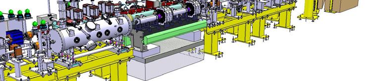
14 Two-beam Test Stand Spectrometers t Experimental area and beam dumps Roger Ruber (Uppsala University) - CLIC Feasibility Demonstration at CTF3 Construction supported by the Swedish Research Council and the Knut and Alice Wallenberg Foundation KVI, 20-Sep

![CLIC] excellent beam diagnostics, long lever arms easy access](/docs-images/85/92596129/images/15-3.jpg "& flexibility for future upgrades Unique test possibilities")

 - CLIC Feasibility Demonstration at CTF3 KVI,")
15 Two-beam Test Stand Prospects Versatile facility two-beam operation 28A drive beam [100A at CLIC] 1A probe beam [like CLIC] excellent beam diagnostics, long lever arms easy access & flexibility for future upgrades Unique test possibilities power production in prototype CLIC PETS two-beam acceleration and full CLIC module studies of beam kick & RF breakdown beam dynamics effects beam-based alignment Roger Ruber (Uppsala University) - CLIC Feasibility Demonstration at CTF3 KVI, 20-Sep


16 TBTS Test Area 1x PETS w/ recirculation 11 March 2010 RR x accelerating structure Roger Ruber (Uppsala University) - Two-beam Test Stand CTF3 Collaboration Meeting (05-16 May-2010)

 4 th X-band Workshop http://indico.cern.")
 CLIC RF struct. dev.")

17 Structures Test Program Drive Beam Area Installed: TBTS PETS, 1m long external RF power recirculation Next test foreseen: PETS On/Off option (active reflector) A. Cappelletti (04-May-2010) 4 th X-band Workshop Probe Beam Area Installed: TD24 = disks, tapered, damped, 24 cells A. Samoshkin (07-Apr-2010) CLIC RF struct. dev. meeting Next test foreseen: TD24 with wakefield monitor Courtesy A. Cappelletti Courtesy A. Samoshkin Roger Ruber (Uppsala University) - Two-beam Test Stand CTF3 Collaboration Meeting (05-17 May-2010)
18 PETS Power Recirculation PETS length 1m, to compensate for lower beam current compared to CLIC External recirculation loop increase PETS power in long pulse, low current mode #3 power recirculation through external feedback loop: electron bunch generates field burst field burst returns after roundtrip time t r = 26ns PETS operates as amplifier (LASER like) phase shifter to adjust phase error in the loop drive beam variable phase shifter PETS input to load variable splitter (coupling: 0 1) PETS output Roger Ruber (Uppsala University) - Two-beam Test Stand CTF3 Collaboration Meeting (05-18 May-2010)
19 Power Reconstruction with Recirculation g = 0.84, φ = -9, c cal = 0.78, c I2E = 0.6 measured = model current model g = , φ = -5, c cal = 0.78, c I2E = 0.6 measured Parameters constant during normal operation predicts PETS output power (CTF3 Note 092, 094, 096) Accurate parameter fit rising slope gives recirculation loop loss factor and phase shift Energy difference (ε) measurement and model indicates pulse shortening breakdown indicator C. Hellenthal, CLIC Note 811 (2009) Roger Ruber (Uppsala University) - Two-beam Test Stand CTF3 Collaboration Meeting (05-19 May-2010)
20 Drive Beam Energy Loss in PETS Energy loss (CTF3 Note 097) spectrometer line (blue) PETS power + BPM intensity (green) BPM intensity (black) Include initial energy variation improves kick measurement (CTF3 Note 098) From E. Adli et al., DIPAC09 MOPD29 Roger Ruber (Uppsala University) - Two-beam Test Stand CTF3 Collaboration Meeting (05-20 May-2010)
21 Two-beam Acceleration Coarse timing drive and probe beam (ns adjustment) assure signals on BPM and RF channels to overlap Calibration of RF system characterize losses in waveguides PETS output RF pulse (shape) == ACS output if no probe beam Demonstrate acceleration by energy gain probe beam scan along PETS 12GHz RF phase (sub-ps timing adjustment, 1 o = 0.23ps): modify laser phase to adjust bunches to PETS phase monitor energy gain Note: acceleration by 15% adjust downstream optics! Roger Ruber (Uppsala University) - Two-beam Test Stand CTF3 Collaboration Meeting (05-21 May-2010)

 Roger Ruber (Uppsala University) - CLIC Feasibility")
22 First Trial Probe Beam Acceleration Fine tuning DB PB timing 3GHz phase scan klystron coherent with 1.5GHz laser timing i signal 19:43 DB ON DB OFF ~6 MeV peak-to-peak p zero crossing: 177 MeV, 205 degr. phase scaling: 5.58 (expect 4x) optimize PB energy spread & bunching klystron pulse compression 20:19 DB ON 20:21 DB OFF coherency klystron and laser low input power (ACS not conditioned) Roger Ruber (Uppsala University) - CLIC Feasibility Demonstration at CTF3 KVI, 20-Sep


 - CLIC")
23 Two-beam Acceleration Probe beam repetition rate is twice the drive beam rep-rate, DB / PB relative timing and phase adjusted to maximize energy and minimize energy spread after ACS, PB pulse length 10 to 100 ns, DB pulse length 100 to 240 ns. Image processing of the spectrum line MTV screen Raw video of the spectrum line MTV screen Roger Ruber (Uppsala University) - CLIC Feasibility Demonstration at CTF3 KVI, 20-Sep

![Gain [Me ev] g Gradient [MV/m]](/docs-images/85/92596129/images/24-3.jpg "Acceleratin ACS in 65 ns ACS out")


 - CLIC Feasibility")
24 Two-beam Acceleration Performance PETS out Ener rgy Gain [Me ev] g Gradient [MV/m] Acceleratin ACS in 65 ns ACS out RF power signals Data logging of energy gain Javier Barranco Tobias Persson ACS accelerating gradient vs. RF Power in Roger Ruber (Uppsala University) - CLIC Feasibility Demonstration at CTF3 KVI, 20-Sep


 - CLIC Feasibility")
25 Conditioning Process Present stable level: PETS + Waveguide Conditioning PETS + recirculation loop ~70 MW peak power, ~200 ns pulse Accelerating structure ~23 MW peak power Accelerating Structure Conditioning Vacuum Activity Roger Ruber (Uppsala University) - CLIC Feasibility Demonstration at CTF3 KVI, 20-Sep


26 Example RF Breakdowns PETS recirculation loop PETS out splitter reflected Accelerating Structure PETS out splitter reflected waveguide waveguide reflected ACS in ACS reflected 3 consecutive pulses ACS through Roger Ruber (Uppsala University) - CLIC Feasibility Demonstration at CTF3 KVI, 20-Sep


27 Breakdown Detection PETS out PETS reflected ACS in 1 ACS reflected 1 ACS in 2 ACS out ACS reflected 2 DB current RF power pannel Alexey Dubrowskiy Photomultiplier and Faraday cup signals during BD Logical analysis of the RF signals allows to attribute breakdown either to the PETS, to the waveguide network or to the ACS PM detection of X-rays and Faraday cup current are typical of ACS breakdowns Flash box will allow to analyze electron and ions current produced during breakdown. Roger Ruber (Uppsala University) - CLIC Feasibility Demonstration at CTF3 KVI, 20-Sep


28 Breakdown Rate ACS breakdown count vs. RF pulse number and repartition law of RF pulse number between BD Breakdown rate vs. accelerating gradient for various periods of time. During a breakdown, in addition to energy default, the beam is likely to receive a transverse kick, It is important for the CLIC design to quantify this effect, BPMs are foreseen for this experiment but are presently affected by noise that limits their resolution, However kicks effects have been recorded using a beam profile monitor. Roger Ruber (Uppsala University) - CLIC Feasibility Demonstration at CTF3 KVI, 20-Sep
29 Beam Kick Measurements M. Johnson, CLIC Note 710 dipole BPM4: x 4 BPM3: x 3 BPM2: x 2 BPM1: x 1 BPM5: x 5 beam kick [θ,δ] 5 BPMs: incoming angle & offset, kick angle dipole + BPM5 for energy measurement Roger Ruber (Uppsala University) - Two-beam Test Stand CTF3 Collaboration Meeting (05-29 May-2010)


 - CLIC Feasibility")
30 Breakdown Kick BP PMs after AC CS BPMs before ACS Volker Ziemann Possible kick recorded during a breakdown Present BPM noise level too high, Measurements with MTV screen instead. Beam without BD Andrea Palaia Beam with BD Kick : 0.2 mrad Roger Ruber (Uppsala University) - CLIC Feasibility Demonstration at CTF3 KVI, 20-Sep

 From E.")
31 Importance of the Drive Beam Kick C08, MOPP002 E. Adli et al., EPAC From E Maximum accepted PETS break down voltage in CLIC transverse voltage required for 1mm offset in drive beam as function of PETS (position) along linac PETS beam kick estimate: (point like bunch, 15GHz) From E. Adli, Thesis (2009) Roger Ruber (Uppsala University) - Two-beam Test Stand CTF3 Collaboration Meeting (05-31 May-2010)


")

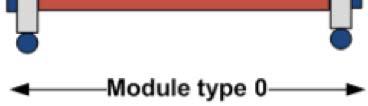
32 TBTS Phase 3: One Test Module Module type 0 double length PETS 8 ACS (4 powered) Roger Ruber (Uppsala University) - Two-beam Test Stand CTF3 Committee Meeting (19-Aug )
33 TBTS Phase 3 Powering Schemes double length PETS at 30 A, barely 65 MW use TBTS PETS for staging Phase (72) MW Klystron + PC (optionally) A RF pulse waveforms 65 10(12) A 108 (81) MW 78 (68.7) MW Existing 1 m PETS with re-circulation Mode 2: no DL, CRx4 max. 15 A, 240 ns A 61 MW 0.5 m PETS 65 MW 65 MW 78 (68.7) MW 7 (10) MW 65 MW Pow wer, MW 65 MW Phase MW Existing 1 m PETS 0.5 m PETS 0.5 m PETS Power, MW CLIC pulse time. ns 1 m PETS power 0.5 PETS priming power Mode 1: DLx2, CRx4 max. 30 A, 140 ns 65 MW 65 MW 17 MW DB current, A Roger Ruber (Uppsala University) - Two-beam Test Stand CTF3 Committee Meeting (19-Aug )
34 Conclusions Reached first milestones: Drive beam generation with appropriate time structure and dfully loaded dacceleration. Two-beam acceleration with CLIC prototype structures. Continued operation: Optimize beam and two-beam acceleration. Investigate RF breakdown effects on beam. Planned enhancements: 12 GHz klystron powered test stand Install full two-beam test modules. Many thanks to all colleagues, their work and their suggestions! Roger Ruber (Uppsala University) - CLIC Feasibility Demonstration at CTF3 KVI, 20-Sep
CLIC Feasibility Demonstration at CTF3
 CLIC Feasibility Demonstration at CTF3 Roger Ruber Uppsala University, Sweden, for the CLIC/CTF3 Collaboration http://cern.ch/clic-study LINAC 10 MO303 13 Sep 2010 The Key to CLIC Efficiency NC Linac for
CLIC FEASIBILITY DEMONSTRATION AT CTF3
 CLIC FEASIBILITY DEMONSTRATION AT CTF3 Abstract The CLIC/CTF3 collaboration is studying the feasibility of a multi-tev electron-positron collider, the so-called CLIC: Compact LInear Collider. The idea
Status of CTF3. G.Geschonke CERN, AB
 Status of CTF3 G.Geschonke CERN, AB CTF3 layout CTF3 - Test of Drive Beam Generation, Acceleration & RF Multiplication by a factor 10 Drive Beam Injector ~ 50 m 3.5 A - 2100 b of 2.33 nc 150 MeV - 1.4
RF considerations for SwissFEL
 RF considerations for H. Fitze in behalf of the PSI RF group Workshop on Compact X-Ray Free Electron Lasers 19.-21. July 2010, Shanghai Agenda Introduction RF-Gun Development C-band development Summary
30 GHz Power Production / Beam Line
 30 GHz Power Production / Beam Line Motivation & Requirements Layout Power mode operation vs. nominal parameters Beam optics Achieved performance Problems Beam phase switch for 30 GHz pulse compression
STATUS AND FUTURE PROSPECTS OF CLIC
 STATUS AND FUTURE PROSPECTS OF CLIC S. Döbert, for the CLIC/CTF3 collaboration, CERN, Geneva, Switzerland Abstract The Compact Linear Collider (CLIC) is studied by a growing international collaboration.
Detailed Design Report
 Detailed Design Report Chapter 4 MAX IV Injector 4.6. Acceleration MAX IV Facility CHAPTER 4.6. ACCELERATION 1(10) 4.6. Acceleration 4.6. Acceleration...2 4.6.1. RF Units... 2 4.6.2. Accelerator Units...
Introduction to CTF3. G.Geschonke CERN / PS
 Introduction to CTF3 G.Geschonke CERN / PS Aim of review: Review the technical solutions are they realistic? Give us technical advice Comment on alternatives Guide our funding bodies: CERN Collaborations
Experience with the Cornell ERL Injector SRF Cryomodule during High Beam Current Operation
 Experience with the Cornell ERL Injector SRF Cryomodule during High Beam Current Operation Matthias Liepe Assistant Professor of Physics Cornell University Experience with the Cornell ERL Injector SRF
Present Status and Future Upgrade of KEKB Injector Linac
 Present Status and Future Upgrade of KEKB Injector Linac Kazuro Furukawa, for e /e + Linac Group Present Status Upgrade in the Near Future R&D towards SuperKEKB 1 Machine Features Present Status and Future
Current status of XFEL/SPring-8 project and SCSS test accelerator
 Current status of XFEL/SPring-8 project and SCSS test accelerator Takahiro Inagaki for XFEL project in SPring-8 inagaki@spring8.or.jp Outline (1) Introduction (2) Key technology for compactness (3) Key
Towards an X-Band Power Source at CERN and a European Structure Test Facility
 Towards an X-Band Power Source at CERN and a European Structure Test Facility Erk Jensen and Gerry McMomagle CERN The X-Band Accelerating Structure Design and Test-Program Workshop Day 2: Structure Testing
LCLS RF Reference and Control R. Akre Last Update Sector 0 RF and Timing Systems
 LCLS RF Reference and Control R. Akre Last Update 5-19-04 Sector 0 RF and Timing Systems The reference system for the RF and timing starts at the 476MHz Master Oscillator, figure 1. Figure 1. Front end
CLEX (CLIC Experimental Area)
") CLEX (CLIC Experimental Area) Status and plans G.Geschonke for Hans Braun CERN CT3 coll meetg 2005 CLEX 1 CT3 objectives R1.1 CLIC accelerating structure, R1.2 rive beam scheme with a fully loaded linac
CLEX (CLIC Experimental Area) Status and plans G.Geschonke for Hans Braun CERN CT3 coll meetg 2005 CLEX 1 CT3 objectives R1.1 CLIC accelerating structure, R1.2 rive beam scheme with a fully loaded linac
4.4 Injector Linear Accelerator
 4.4 Injector Linear Accelerator 100 MeV S-band linear accelerator based on the components already built for the S-Band Linear Collider Test Facility at DESY [1, 2] will be used as an injector for the CANDLE
Photoinjector Laser Operation and Cathode Performance
 Photoinjector Laser Operation and Cathode Performance Daniele Sertore, INFN Milano LASA Siegfried Schreiber, DESY Laser operational experience Laser beam properties Cathode performances Outlook TTF and
STATUS OF THE SWISSFEL C-BAND LINEAR ACCELERATOR
 Proceedings of FEL213, New York, NY, USA STATUS OF THE SWISSFEL C-BAND LINEAR ACCELERATOR F. Loehl, J. Alex, H. Blumer, M. Bopp, H. Braun, A. Citterio, U. Ellenberger, H. Fitze, H. Joehri, T. Kleeb, L.
The basic parameters of the pre-injector are listed in the Table below. 100 MeV
 3.3 The Pre-injector The high design brightness of the SLS requires very high phase space density of the stored electrons, leading to a comparatively short lifetime of the beam in the storage ring. This,
3 cerl. 3-1 cerl Overview. 3-2 High-brightness DC Photocathode Gun and Gun Test Beamline
 3 cerl 3-1 cerl Overview As described before, the aim of the cerl in the R&D program includes the development of critical components for the ERL, as well as the construction of a test accelerator. The
Precision measurements of beam current, position and phase for an e+e- linear collider
 Precision measurements of beam current, position and phase for an e+e- linear collider R. Corsini on behalf of H. Braun, M. Gasior, S. Livesley, P. Odier, J. Sladen, L. Soby INTRODUCTION Commissioning
2 Work Package and Work Unit descriptions. 2.8 WP8: RF Systems (R. Ruber, Uppsala)
") 2 Work Package and Work Unit descriptions 2.8 WP8: RF Systems (R. Ruber, Uppsala) The RF systems work package (WP) addresses the design and development of the RF power generation, control and distribution
2 Work Package and Work Unit descriptions 2.8 WP8: RF Systems (R. Ruber, Uppsala) The RF systems work package (WP) addresses the design and development of the RF power generation, control and distribution
Upgrading LHC Luminosity
 1 Upgrading LHC Luminosity 2 Luminosity (cm -2 s -1 ) Present (2011) ~2 x10 33 Beam intensity @ injection (*) Nominal (2015?) 1 x 10 34 1.1 x10 11 Upgraded (2021?) ~5 x10 34 ~2.4 x10 11 (*) protons per
THE NEXT LINEAR COLLIDER TEST ACCELERATOR: STATUS AND RESULTS * Abstract
 SLAC PUB 7246 June 996 THE NEXT LINEAR COLLIDER TEST ACCELERATOR: STATUS AND RESULTS * Ronald D. Ruth, SLAC, Stanford, CA, USA Abstract At SLAC, we are pursuing the design of a Next Linear Collider (NLC)
The FLASH objective: SASE between 60 and 13 nm
 Injector beam control studies winter 2006/07 talk from E. Vogel on work performed by W. Cichalewski, C. Gerth, W. Jalmuzna,W. Koprek, F. Löhl, D. Noelle, P. Pucyk, H. Schlarb, T. Traber, E. Vogel, FLASH
Photo cathode RF gun -
 Photo cathode RF gun - *),,, ( 05 Nov. 2004 Spring8 UTNL Linac & Mg Photocathode RF Gun Mg photocathode NERL, 18 MeV Linac and the RF gun Electron Beam Mg photocathode Mg photocathode RF gun of SPring8
Digital BPMs and Orbit Feedback Systems
 Digital BPMs and Orbit Feedback Systems, M. Böge, M. Dehler, B. Keil, P. Pollet, V. Schlott Outline stability requirements at SLS storage ring digital beam position monitors (DBPM) SLS global fast orbit
Diamond RF Status (RF Activities at Daresbury) Mike Dykes
 Mike Dykes") Diamond RF Status (RF Activities at Daresbury) Mike Dykes ASTeC What is it? What does it do? Diamond Status Linac Booster RF Storage Ring RF Summary Content ASTeC ASTeC was formed in 2001 as a centre of
Diamond RF Status (RF Activities at Daresbury) Mike Dykes ASTeC What is it? What does it do? Diamond Status Linac Booster RF Storage Ring RF Summary Content ASTeC ASTeC was formed in 2001 as a centre of
RUNNING EXPERIENCE OF FZD SRF PHOTOINJECTOR
 RUNNING EXPERIENCE OF FZD SRF PHOTOINJECTOR Rong Xiang On behalf of the BESSY-DESY-FZD-MBI collaboration and the ELBE team FEL 2009, Liverpool, United Kingdom, August 23 ~ 28, 2009 Outline Introduction
Summary of the 1 st Beam Line Review Meeting Injector ( )
") Summary of the 1 st Beam Line Review Meeting Injector (23.10.2006) 15.11.2006 Review the status of: beam dynamics understanding and simulations completeness of beam line description conceptual design of
Summary of the 1 st Beam Line Review Meeting Injector (23.10.2006) 15.11.2006 Review the status of: beam dynamics understanding and simulations completeness of beam line description conceptual design of
Activities on FEL Development and Application at Kyoto University
 Activities on FEL Development and Application at Kyoto University China-Korea-Japan Joint Workshop on Electron / Photon Sources and Applications Dec. 2-3, 2010 @ SINAP, Shanghai Kai Masuda Inst. Advanced
J/NLC Progress on R1 and R2 Issues. Chris Adolphsen
 J/NLC Progress on R1 and R2 Issues Chris Adolphsen Charge to the International Linear Collider Technical Review Committee (ILC-TRC) To assess the present technical status of the four LC designs at hand,
Status of RF Power and Acceleration of the MAX IV - LINAC
 Status of RF Power and Acceleration of the MAX IV - LINAC Dionis Kumbaro ESLS RF Workshop 2015 MAX IV Laboratory A National Laboratory for synchrotron radiation at Lunds University 1981 MAX-lab is formed
IOT OPERATIONAL EXPERIENCE ON ALICE AND EMMA AT DARESBURY LABORATORY
 IOT OPERATIONAL EXPERIENCE ON ALICE AND EMMA AT DARESBURY LABORATORY A. Wheelhouse ASTeC, STFC Daresbury Laboratory ESLS XVIII Workshop, ELLETRA 25 th 26 th November 2010 Contents Brief Description ALICE
Beam Instrumentation for CTF3 and CLIC
 Beam Instrumentation for CTF3 and CLIC Beam loss - Beam halo monitoring developments CLIC diagnostic Common developments with other projects Specific requirements for CLIC Beam Loss and Beam Halo measurement
Linac 4 Instrumentation K.Hanke CERN
 Linac 4 Instrumentation K.Hanke CERN CERN Linac 4 PS2 (2016?) SPL (2015?) Linac4 (2012) Linac4 will first inject into the PSB and then can be the first element of a new LHC injector chain. It will increase
TWO BUNCHES WITH NS-SEPARATION WITH LCLS*
 TWO BUNCHES WITH NS-SEPARATION WITH LCLS* F.-J. Decker, S. Gilevich, Z. Huang, H. Loos, A. Marinelli, C.A. Stan, J.L. Turner, Z. van Hoover, S. Vetter, SLAC, Menlo Park, CA 94025, USA Abstract The Linac
Report on the LCLS Injector Technical Review
 Report on the LCLS Injector Technical Review Stanford Linear Accelerator Center November 3&4, 2003 Committee Members Prof. Patrick G. O Shea, Chair, University of Maryland Dr. Eric Colby, Stanford Linear
P. Emma, et al. LCLS Operations Lectures
 P. Emma, et al. LCLS Operations Lectures LCLS 1 LCLS Accelerator Schematic 6 MeV 135 MeV 250 MeV σ z 0.83 mm σ z 0.83 mm σ z 0.19 mm σ δ 0.05 % σ δ 0.10 % σ δ 1.6 % Linac-0 L =6 m rf gun L0-a,b Linac-1
45 MW, 22.8 GHz Second-Harmonic Multiplier for High-Gradient Tests*
 US High Gradient Research Collaboration Workshop. SLAC, May 23-25, 2007 45 MW, 22.8 GHz Second-Harmonic Multiplier for High-Gradient Tests* V.P. Yakovlev 1, S.Yu. Kazakov 1,2, and J.L. Hirshfield 1,3 1
KARA and FLUTE RF Overview/status
 KARA and FLUTE RF Overview/status Nigel Smale on behalf of IBPT and LAS teams Laboratory for Applications of Synchrotron radiation (LAS) Institute for Beam Physics and Technology (IBPT) KARA KIT The Research
The PEFP 20-MeV Proton Linear Accelerator
 Journal of the Korean Physical Society, Vol. 52, No. 3, March 2008, pp. 721726 Review Articles The PEFP 20-MeV Proton Linear Accelerator Y. S. Cho, H. J. Kwon, J. H. Jang, H. S. Kim, K. T. Seol, D. I.
New Filling Pattern for SLS-FEMTO
 SLS-TME-TA-2009-0317 July 14, 2009 New Filling Pattern for SLS-FEMTO Natalia Prado de Abreu, Paul Beaud, Gerhard Ingold and Andreas Streun Paul Scherrer Institut, CH-5232 Villigen PSI, Switzerland A new
Design Studies For The LCLS 120 Hz RF Gun Injector
 BNL-67922 Informal Report LCLS-TN-01-3 Design Studies For The LCLS 120 Hz RF Gun Injector X.J. Wang, M. Babzien, I. Ben-Zvi, X.Y. Chang, S. Pjerov, and M. Woodle National Synchrotron Light Source Brookhaven
STATUS OF THE SwissFEL C-BAND LINAC
 STATUS OF THE SwissFEL C-BAND LINAC F. Loehl, J. Alex, H. Blumer, M. Bopp, H. Braun, A. Citterio, U. Ellenberger, H. Fitze, H. Joehri, T. Kleeb, L. Paly, J.-Y. Raguin, L. Schulz, R. Zennaro, C. Zumbach,
Beam Instrumentation for X-ray FELs
 Beam Instrumentation for X-ray FELs 05/16/2011 1 1 Outline X-ray FEL overview Diagnostics requirements for X-ray FELs Transverse Diagnostics Longitudinal Diagnostics Summary 2 2 X-ray FEL Overview 100
Suggested ILC Beam Parameter Range Rev. 2/28/05 Tor Raubenheimer
 The machine parameters and the luminosity goals of the ILC were discussed at the 1 st ILC Workshop. In particular, Nick Walker noted that the TESLA machine parameters had been chosen to achieve a high
LHC Beam Instrumentation Further Discussion
 LHC Beam Instrumentation Further Discussion LHC Machine Advisory Committee 9 th December 2005 Rhodri Jones (CERN AB/BDI) Possible Discussion Topics Open Questions Tune measurement base band tune & 50Hz
Accelerator Instrumentation RD. Monday, July 14, 2003 Marc Ross
 Monday, Marc Ross Linear Collider RD Most RD funds address the most serious cost driver energy The most serious impact of the late technology choice is the failure to adequately address luminosity RD issues
TESLA FEL-Report
 Determination of the Longitudinal Phase Space Distribution produced with the TTF Photo Injector M. Geitz a,s.schreiber a,g.von Walter b, D. Sertore a;1, M. Bernard c, B. Leblond c a Deutsches Elektronen-Synchrotron,
Studies on an S-band bunching system with hybrid buncher
 Submitted to Chinese Physics C Studies on an S-band bunching system with hybrid buncher PEI Shi-Lun( 裴士伦 ) 1) XIAO Ou-Zheng( 肖欧正 ) Institute of High Energy Physics, Chinese Academy of Sciences, Beijing
Beam Losses During LCLS Injector Phase-1 1 Operation
 Beam Losses During LCLS Injector Phase-1 1 Operation & Paul Emma September 28, 2006 Radiation Safety Committee Review Scope of Phase 1 Operation Request for Three Operating Modes Operating Plan for Phase
Position Resolution of Optical Fibre-Based Beam Loss Monitors using long electron pulses
 Position Resolution of Optical Fibre-Based Beam Loss Monitors using long electron pulses E. Nebot del Busto (1,2, 3), M. J. Boland (4,5), S. Doebert (1), F. S. Domingues (1), E. Effinger (1), W. Farabolini
Next Linear Collider. The 8-Pack Project. 8-Pack Project. Four 50 MW XL4 X-band klystrons installed on the 8-Pack
 The Four 50 MW XL4 X-band klystrons installed on the 8-Pack The Demonstrate an NLC power source Two Phases: 8-Pack Phase-1 (current): Multi-moded SLED II power compression Produce NLC baseline power: 475
SUMMARY OF THE ILC R&D AND DESIGN
 SUMMARY OF THE ILC R&D AND DESIGN B. C. Barish, California Institute of Technology, USA Abstract The International Linear Collider (ILC) is a linear electron-positron collider based on 1.3 GHz superconducting
TITLE PAGE. Title of paper: PUSH-PULL FEL, A NEW ERL CONCEPT Author: Andrew Hutton. Author Affiliation: Jefferson Lab. Requested Proceedings:
 TITLE PAGE Title of paper: PUSH-PULL FEL, A NEW ERL CONCEPT Author: Andrew Hutton Author Affiliation: Jefferson Lab Requested Proceedings: Unique Session ID: Classification Codes: Keywords: Energy Recovery,
Operational experience with the SOLEIL LINAC and Status of the ThomX LINAC project
 Operational experience with the SOLEIL LINAC and Status of the ThomX LINAC project 16/11/2016 20th ELS-RF Workshop Pollina JP 1 and Status of the ThomX LINAC project Operational experience with the SOLEIL
Jefferson Lab Experience with Beam Halo, Beam Loss, etc.
 Jefferson Lab Experience with Beam Halo, Beam Loss, etc. Pavel Evtushenko with a lot of input from many experienced colleagues Steve Benson, Dave Douglas, Kevin Jordan, Carlos Hernandez-Garcia, Dan Sexton,
Commissioning of Accelerators. Dr. Marc Munoz (with the help of R. Miyamoto, C. Plostinar and M. Eshraqi)
") Commissioning of Accelerators Dr. Marc Munoz (with the help of R. Miyamoto, C. Plostinar and M. Eshraqi) www.europeanspallationsource.se 6 July, 2017 Contents General points Definition of Commissioning
Commissioning of Accelerators Dr. Marc Munoz (with the help of R. Miyamoto, C. Plostinar and M. Eshraqi) www.europeanspallationsource.se 6 July, 2017 Contents General points Definition of Commissioning
EPJ Web of Conferences 95,
 EPJ Web of Conferences 95, 04012 (2015) DOI: 10.1051/ epjconf/ 20159504012 C Owned by the authors, published by EDP Sciences, 2015 The ELENA (Extra Low Energy Antiproton) project is a small size (30.4
The FAIR plinac RF Systems
 The FAIR plinac RF Systems Libera Workshop Sep. 2011 Gerald Schreiber Gerald Schreiber, GSI RF Department 2 (1) Overview GSI / FAIR (2) FAIR Proton Linear Accelerator "plinac" (3) plinac RF Systems (4)
Status of BESSY II and berlinpro. Wolfgang Anders. Helmholtz-Zentrum Berlin for Materials and Energy (HZB) 20th ESLS-RF Meeting
 20th ESLS-RF Meeting") Status of BESSY II and berlinpro Wolfgang Anders Helmholtz-Zentrum Berlin for Materials and Energy (HZB) 20th ESLS-RF Meeting 16.-17.11.2016 at PSI Outline BESSY II Problems with circulators Landau cavity
Status of BESSY II and berlinpro Wolfgang Anders Helmholtz-Zentrum Berlin for Materials and Energy (HZB) 20th ESLS-RF Meeting 16.-17.11.2016 at PSI Outline BESSY II Problems with circulators Landau cavity
INFN School on Electron Accelerators. RF Power Sources and Distribution
 INFN School on Electron Accelerators 12-14 September 2007, INFN Sezione di Pisa Lecture 7b RF Power Sources and Distribution Carlo Pagani University of Milano INFN Milano-LASA & GDE The ILC Double Tunnel
STATUS AND COMMISSIONING RESULTS OF THE R&D ERL AT BNL*
 STATUS AND COMMISSIONING RESULTS OF THE R&D ERL AT BNL* D. Kayran #,1,2, Z. Altinbas 1, D. Beavis 1, S. Belomestnykh 1,2, I. Ben-Zvi 1,2, S. Deonarine 1, D.M. Gassner 1, R. C. Gupta 1, H. Hahn 1,L.R. Hammons
Basic rules for the design of RF Controls in High Intensity Proton Linacs. Particularities of proton linacs wrt electron linacs
 Basic rules Basic rules for the design of RF Controls in High Intensity Proton Linacs Particularities of proton linacs wrt electron linacs Non-zero synchronous phase needs reactive beam-loading compensation
High Brightness Injector Development and ERL Planning at Cornell. Charlie Sinclair Cornell University Laboratory for Elementary-Particle Physics
 High Brightness Injector Development and ERL Planning at Cornell Charlie Sinclair Cornell University Laboratory for Elementary-Particle Physics June 22, 2006 JLab CASA Seminar 2 Background During 2000-2001,
PEP II Design Outline
 PEP II Design Outline Balša Terzić Jefferson Lab Collider Review Retreat, February 24, 2010 Outline General Information Parameter list (and evolution), initial design, upgrades Collider Ring Layout, insertions,
An Overview of Beam Diagnostic and Control Systems for AREAL Linac
 An Overview of Beam Diagnostic and Control Systems for AREAL Linac Presenter G. Amatuni Ultrafast Beams and Applications 04-07 July 2017, CANDLE, Armenia Contents: 1. Current status of existing diagnostic
beam dump from P2 losses this morning
 beam dump from P2 losses this morning Some observations on the beam dump from P2 losses this morning 29.10.10 at 01:26:39: - single bunch intensity (average) was ~1.3e11 - significantly higher than previous
First Simultaneous Top-up Operation of Three Different Rings in KEK Injector Linac
 First Simultaneous Top-up Operation of Three Different Rings in KEK Injector Linac Masanori Satoh (Acc. Lab., KEK) for the injector upgrade group 2010/9/16 1 Overview of Linac Beam Operation 2010/9/16
FIRST SIMULTANEOUS TOP-UP OPERATION OF THREE DIFFERENT RINGS IN KEK INJECTOR LINAC
 FIRST SIMULTANEOUS TOP-UP OPERATION OF THREE DIFFERENT RINGS IN KEK INJECTOR LINAC M. Satoh #, for the IUC * Accelerator Laboratory, High Energy Accelerator Research Organization (KEK) 1-1 Oho, Tsukuba,
Suppression of Timing drift between laser and electron beam driven photo-cathode RF gun
 Suppression of Timing drift between laser and electron beam driven photo-cathode RF gun A. Sakumi, M. Uesaka, Y. Muroya, T. Ueda Nuclear Professional School, University of Tokyo J. Urakawa, KEK, Japan
North Damping Ring RF
 North Damping Ring RF North Damping Ring RF Outline Overview High Power RF HVPS Klystron & Klystron EPICS controls Cavities & Cavity Feedback SCP diagnostics & displays FACET-specific LLRF LLRF distribution
NLC - The Next Linear Collider Project NLC R&D. D. L. Burke. DOE Annual Program Review SLAC April 9-11, 2003
 DOE Annual Program Review SLAC April 9-11, 2003 NLC Activities for the Past Year Accelerator Design centered around ILC-TRC studies. Technology R&D focused on the RF R&D. Modulator, klystron, SLED-II,
Commissioning the TAMUTRAP RFQ cooler/buncher. E. Bennett, R. Burch, B. Fenker, M. Mehlman, D. Melconian, and P.D. Shidling
 Commissioning the TAMUTRAP RFQ cooler/buncher E. Bennett, R. Burch, B. Fenker, M. Mehlman, D. Melconian, and P.D. Shidling In order to efficiently load ions into a Penning trap, the ion beam should be
Tutorial: Trak design of an electron injector for a coupled-cavity linear accelerator
 Tutorial: Trak design of an electron injector for a coupled-cavity linear accelerator Stanley Humphries, Copyright 2012 Field Precision PO Box 13595, Albuquerque, NM 87192 U.S.A. Telephone: +1-505-220-3975
High Rep Rate Guns: FZD Superconducting RF Photogun
 High Rep Rate Guns: FZD Superconducting RF Photogun J. Teichert, A. Arnold, H. Büttig, D. Janssen, M. Justus, U. Lehnert, P. Michel, K. Moeller, P. Murcek, Ch. Schneider, R. Schurig, G. Staats, F. Staufenbiel,
PoS(EPS-HEP2015)525. The RF system for FCC-ee. A. Butterworth CERN 1211 Geneva 23, Switzerland
525. The RF system for FCC-ee. A. Butterworth CERN 1211 Geneva 23, Switzerland") CERN 1211 Geneva 23, Switzerland E-mail: andrew.butterworth@cern.ch O. Brunner CERN 1211 Geneva 23, Switzerland E-mail: olivier.brunner@cern.ch R. Calaga CERN 1211 Geneva 23, Switzerland E-mail: rama.calaga@cern.ch
CERN 1211 Geneva 23, Switzerland E-mail: andrew.butterworth@cern.ch O. Brunner CERN 1211 Geneva 23, Switzerland E-mail: olivier.brunner@cern.ch R. Calaga CERN 1211 Geneva 23, Switzerland E-mail: rama.calaga@cern.ch
Simulations on Beam Monitor Systems for Longitudinal Feedback Schemes at FLASH.
 Simulations on Beam Monitor Systems for Longitudinal Feedback Schemes at FLASH. Christopher Behrens for the FLASH team Deutsches Elektronen-Synchrotron (DESY) FLS-2010 Workshop at SLAC, 4. March 2010 C.
The Elettra Storage Ring and Top-Up Operation
 The Elettra Storage Ring and Top-Up Operation Emanuel Karantzoulis Past and Present Configurations 1994-2007 From 2008 5000 hours /year to the users 2010: Operations transition year Decay mode, 2 GeV (340mA)
Dark current and multipacting trajectories simulations for the RF Photo Gun at PITZ
 Dark current and multipacting trajectories simulations for the RF Photo Gun at PITZ Introduction The PITZ RF Photo Gun Field simulations Dark current simulations Multipacting simulations Summary Igor Isaev
XFEL High Power RF System Recent Developments
 XFEL High Power RF System Recent Developments for the XFEL RF Group Outline XFEL RF System Requirements Overview Basic Layout RF System Main Components Multibeam Klystrons Modulator RF Waveguide Distribution
PROJECT DESCRIPTION. Longitudinal phase space monitors for the ILC injectors and bunch compressors
 PROJECT DESCRIPTION Longitudinal phase space monitors for the ILC injectors and bunch compressors Personnel and Institution(s) requesting funding Philippe Piot Northern Illinois University Dept of Physics,
STATUS OF THE INTERNATIONAL LINEAR COLLIDER
 STATUS OF THE INTERNATIONAL LINEAR COLLIDER K. Yokoya, KEK, Tsukuba, Japan Abstract The International Linear Collider (ILC) is the nextgeneration electron-positron collider. Since the publication of the
Low Level RF for PIP-II. Jonathan Edelen LLRF 2017 Workshop (Barcelona) 16 Oct 2017
 16 Oct 2017") Low Level RF for PIP-II Jonathan Edelen LLRF 2017 Workshop (Barcelona) 16 Oct 2017 PIP-II LLRF Team Fermilab Brian Chase, Edward Cullerton, Joshua Einstein, Jeremiah Holzbauer, Dan Klepec, Yuriy Pischalnikov,
Low Level RF for PIP-II Jonathan Edelen LLRF 2017 Workshop (Barcelona) 16 Oct 2017 PIP-II LLRF Team Fermilab Brian Chase, Edward Cullerton, Joshua Einstein, Jeremiah Holzbauer, Dan Klepec, Yuriy Pischalnikov,
Status of KEK X-band Test Facility and its future plans
 Status of KEK X-band Test Facility and its future plans Shuji Matsumoto Accelerator Lab., KEK 5/30/2007 US High Field Gradient Collaboration Workshop, SLAC. 1 Contents The New X-band Test Facility (XTF)
Overview of the X-band R&D Program
 Overview of the X-band R&D Program SLAC-PUB-9442 August 2002 Abstract T.O. Raubenheimer Stanford Linear Accelerator Center, Stanford University, Stanford, California 94309 USA An electron/positron linear
Future Performance of the LCLS
 Future Performance of the LCLS J. Welch for many* SLAC National Accelerator Laboratory FLS 2010, ICFA Beam Dynamics Workshop on Future Light Sources, March 1-5, 2010. SLAC National Accelerator Laboratory,
KEKB INJECTOR LINAC AND UPGRADE FOR SUPERKEKB
 KEKB INJECTOR LINAC AND UPGRADE FOR SUPERKEKB S. Michizono for the KEK electron/positron Injector Linac and the Linac Commissioning Group KEK KEKB injector linac Brief history of the KEK electron linac
Bunch-by-bunch feedback and LLRF at ELSA
 Bunch-by-bunch feedback and LLRF at ELSA Dmitry Teytelman Dimtel, Inc., San Jose, CA, USA February 9, 2010 Outline 1 Feedback Feedback basics Coupled-bunch instabilities and feedback Beam and feedback
Status of SOLARIS. Paweł Borowiec On behalf of Solaris Team
 Status of SOLARIS Paweł Borowiec On behalf of Solaris Team e-mail: pawel.borowiec@uj.edu.pl XX ESLS-RF Meeting, Villingen 16-17.11.2016 Outline 1. Timeline 2. Injector 3. Storage ring 16-17.11.2016 XX
Phase (deg) Phase (deg) Positive feedback, 317 ma. Negative feedback, 330 ma. jan2898/1638: beam pseudospectrum around 770*frev.
 Phase (deg) Positive feedback, 317 ma. Negative feedback, 330 ma. jan2898/1638: beam pseudospectrum around 770*frev.") Commissioning Experience from PEP-II HER Longitudinal Feedback 1 S. Prabhakar, D. Teytelman, J. Fox, A. Young, P. Corredoura, and R. Tighe Stanford Linear Accelerator Center, Stanford University, Stanford,
Commissioning Experience from PEP-II HER Longitudinal Feedback 1 S. Prabhakar, D. Teytelman, J. Fox, A. Young, P. Corredoura, and R. Tighe Stanford Linear Accelerator Center, Stanford University, Stanford,
Screen investigations for low energetic electron beams at PITZ
 1 Screen investigations for low energetic electron beams at PITZ S. Rimjaem, J. Bähr, H.J. Grabosch, M. Groß Contents Review of PITZ setup Screens and beam profile monitors at PITZ Test results Summary
A HIGH-POWER SUPERCONDUCTING H - LINAC (SPL) AT CERN
 AT CERN") A HIGH-POWER SUPERCONDUCTING H - LINAC (SPL) AT CERN E. Chiaveri, CERN, Geneva, Switzerland Abstract The conceptual design of a superconducting H - linear accelerator at CERN for a beam energy of 2.2 GeV
A HIGH-POWER SUPERCONDUCTING H - LINAC (SPL) AT CERN E. Chiaveri, CERN, Geneva, Switzerland Abstract The conceptual design of a superconducting H - linear accelerator at CERN for a beam energy of 2.2 GeV
News from HZB / BESSY Wolfgang Anders at ESLS-RF Meeting September 2010 Trieste
 News from HZB / BESSY Wolfgang Anders at ESLS-RF Meeting September 2010 Trieste Outline Status Klystrons / IOT Modifications of transmitters New LINAC for BESSY II Status BERLinPro HoBiCaT Extension --
Status of the X-ray FEL control system at SPring-8
 Status of the X-ray FEL control system at SPring-8 T.Fukui 1, T.Hirono 2, N.Hosoda 1, M.Ishii 2, M.Kitamura 1 H.Maesaka 1,T.Masuda 2, T.Matsushita 2, T.Ohata 2, Y.Otake 1, K.Shirasawa 1,M.Takeuchi 2, R.Tanaka
Cathode Studies at FLASH: CW and Pulsed QE measurements
 Cathode Studies at FLASH: CW and Pulsed QE measurements L. Monaco, D. Sertore, P. Michelato S. Lederer, S. Schreiber Work supported by the European Community (contract number RII3-CT-2004-506008) 1/27
Development of beam-collision feedback systems for future lepton colliders. John Adams Institute for Accelerator Science, Oxford University
 Development of beam-collision feedback systems for future lepton colliders P.N. Burrows 1 John Adams Institute for Accelerator Science, Oxford University Denys Wilkinson Building, Keble Rd, Oxford, OX1
Linac upgrade plan using a C-band system for SuperKEKB
 Linac upgrade plan using a C-band system for SuperKEKB S. Fukuda, M. Akemono, M. Ikeda, T. Oogoe, T. Ohsawa, Y. Ogawa, K. Kakihara, H. Katagiri, T. Kamitani, M. Sato, T. Shidara, A. Shirakawa, T. Sugimura,
Jae-Young Choi On behalf of PLS-II Linac team
 PLS-II Linac 2015. 4. 8. Jae-Young Choi On behalf of PLS-II Linac team Accelerators in Pohang Accelerator Laboratory XFEL (under construction) 400 M$ Machines under installation PLS-II PAL : Chronology
DELIVERY RECORD. Location: Ibaraki, Japan
 DELIVERY RECORD Client: Japan Atomic Energy Agency (JAEA) High Energy Accelerator Research Organization (KEK) Facility: J-PARC (Japan Proton Accelerator Research Complex) Location: Ibaraki, Japan 1 October