Low-Noise, High-Efficiency and High-Quality Magnetron for Microwave Oven
|
|
|
- Magdalene Atkinson
- 5 years ago
- Views:
Transcription


1 Low-Noise, High-Efficiency and High-Quality Magnetron for Microwave Oven N. Kuwahara 1*, T. Ishii 1, K. Hirayama 2, T. Mitani 2, N. Shinohara 2 1 Panasonic corporation, Noji-higashi, Kusatsu City, Shiga, , Japan 2 Research Institute for Sustainable Humanosphere, Kyoto University Gokasho, Uji, Kyoto, , Japan * Kuwahara.nagisa@jp.panasonic.com Introduction Nowadays, the considerations of energy-efficiency performance in microwave ovens are also required due to environmental concerns. However, stricter restrictions on electromagnetic noise are also promoted all over the world. Therefore, we have been required to develop a magnetron which properly meets the CISPR standard (dictated by the Comité International Spécial des Perturbations Radioélectriques) and yet operates at high efficiency. However, the magnetron s efficiency and noise parameters have a trade-off relation, which makes it difficult to satisfy the condition of low noise and high efficiency r. We solved the problem using Panasonic industrial magnetron technology, and also succeeded in achieving high-quality devices. ExB drift motion. The gyration of the electrons resonates to a number of resonators at the anode. A bunching effect occurs hence the microwave field is amplified by the rotating electron pole, which leads to oscillations. Methodology 1. Theory of magnetron efficiency The magnetron s efficiency η is given by: 2 mv ra + rc ω η = ηc 1 ηc 1 2eV ra rc n eb m ω, (1) where η c is the circuit s efficiency, e, m and v are the electron charge, mass, and velocity, respectively, V is the anode voltage; ra and rc are the anode and cathode radiuses, respectively, ω is the angular frequency, n is the number of resonators, and B is the magnetic field. It is necessary to reduce the electron velocity v in order to raise the magnetron efficiency (1). In this trend, the action space size is narrowed, the magnetic field is intensified, and the number of anode resonators is increased. 2. Noise generation factor of magnetron The magnetron is a cylindrical structure with coaxial cathode and anode (Fig. 1). The electrons perform a rotational motion due to the radial electric field and the axial magnetic field. This rotation is termed the 21 Figure 1: The action space of magnetron The noise generation factors that have been reported in the past are as follows: Noise synchronized with the surrounding electron. Noise by ion plasma vibration. Noise by ion relaxation vibration. Noise by intermodulation. The noise is divided roughly into three bands (Fig. 2): Fundamental wave at 2.45 GHz. Line noise and radiation noise. High harmonic noise. The methods of noise control studied earlier are: Electronic motion control at both axial ends. Axial magnetic field uniformity. Electrical discharge suppression. Oscillation frequency band narrowing. Space charge layer width decrease. The π-1 oscillation mode separation and control (increase the resonance Q value).
, which is a solver module of CST STUDIO SUITE.")
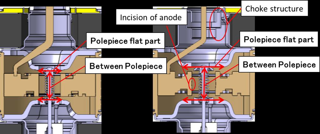
2 Figure 2: Magnetron s noise bands. 3. Approach to high efficiency and low noise We used the theory mentioned above and CAE to achieve both low noise and a high efficiency. The details are described below. We analyzed the magnetron operation using CST Particle Studio (hereafter, CST PS), which is a solver module of CST STUDIO SUITE. This simulator can analyze grain motion in three dimensions by using Maxwell s and motion equations of charged particles (hereafter, particles). We modeled and simulated two magnetron shapes (QV and J versions, for a high-efficiency and low-noise specifications, respectively) for actual microwave ovens. The two models are shown in Figs. 3a, b. First, we simulated each model in a uniformed magnetic field distribution. The particle distributions are shown in Fig. 4, and the output voltage changes in timeline are shown in Fig. 5. Figures 4a, b show that the kinetic energy of the particles reaching the anode in J-version is higher than that of QV-version, and also more particles reach the anode vane. In addition, Fig. 5 shows that the time in which the voltage amplitude increases and stabilizes is shorter in QV-version. Consequently, as shown in Table 1, we succeeded to reproduce the feature that QV-version is more efficient than J-version. However, the difference between the theoretical efficiency value and that calculated was about 2-6%. It causes that the electron efficiency loss is reduced due to the radial component of the velocity of the particles, accelerated in the cavity resonator. This effect is not included in the theoretical efficiency. Figure 6 shows the result of the frequency spectra obtained by applying a Fast Fourier Transform (FFT) to the output voltage time variation. We could not find the spectrum for frequencies below 1 GHz. The reasons are because we could not reproduce the limitation of time resolution in the simulation, and the filament temperature change due to secondary electron emission and back bombardment. The next simulation was carried out using actual magnetic field distribution as shown in Fig. 7. As a result, the calculated efficiency of both QV-version and J-version decreased about 10% in the actual magnetic field compared with a uniform magnetic field as shown in Table 1. We presumed that it was because the particles in the central portion in the axial direction were likely to be pulled out to the anode portion, and because the number of particles entering into the cavity resonator was increased and the kinetic energy increased more than in the case of the uniform magnetic field. Regarding the noise performance, the frequency spectrum other than the fundamental wave (around 2.45 GHz) became higher in the actual magnetic field than in the uniform magnetic field. Thus, in order to achieve high efficiency, while ensuring low noise, it is best to make the actual magnetic field close to the uniform magnetic field, after reducing the electron motion space (the anode inner radius; ra and the cathode outer radius; rc). In order to be close to the uniform magnetic field, we focused on the ratio (hereafter the current ratio ) by separating the anode into three parts at equal intervals in the axial direction, and calculating the anode current of each portion. For that we define three separated parts the anode A side, the anode central part, and the anode K side from the anode vane on the output end side. As a result of obtaining an optimal solution that makes the current ratio as uniform as possible, as shown in Table 2, we successfully established a U-version that improves the efficiency by 5% while the current ratio is equivalent to J- version. 4. Approach to high quality Regarding the factors that cause variations in the production process, we again checked the influence of the frequency spectrum by simulation and some experiments. As shown in Fig. 8, we found that the most adverse effect took place when the coaxial displacement of the electron motion in space occurred, that is, in the active space between the anode inner radius ra and the cathode outer radius rc. 22


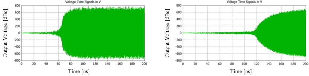

3 Figure 3: Magnetron model Figure 4: Particle distribution Figure 5: Evolution of the output voltage with time 23


 CAE results Uniform")

4 Figure 6: Frequency spectrum from FFT Figure 7: Magnetic field distribution Figure 8: Axial and radial particle distribution (coaxial displacement) Table 1. Comparison of efficiencies Magnetron Type Theory calculation value Equation (1) CAE results Uniform magnetic field CAE results Actual magnetic field Current High-efficiency QV-version Current Low-Noise J-version 77.6% 74.9% 76.4% 68.4% 66.6% 56.9% I 24

.")

5 It was also noticed that the frequency change increased due to altering the distance between the cathode and the anode in the axial direction. Therefore, we also incorporated the technologies of industrial magnetrons and reexamined the dimensions, jigs and equipment, for a stabilized quality design. Results The performance of the newly developed magnetron using a waveguide measurement system is shown in Table 3. The noise performance on a microwave oven is shown in Fig. 10. In addition, the durability test results are shown in Fig. 11, which show that the life time has been longer than 5,000 hours (while the magnetron is still working). Figure 11: Durability test data Magnetron Type Table 2. Comparison of efficiencies QV-version J-version New U-version Total anode current 1.88 A 1.98 A 1.92 A A-side 8.2 % 23.5 % 24.6 % Center 67.0 % 43.7 % 41.3 % K-side 24.8 % 32.8 % 34.1 % CAE results, efficiency 66.6 % 56.9% 62.0 % Magnetron Type Table 3. Comparison of specifications to the present Panasonic magnetrons Current High-efficiency QV-version Current Low-Noise J-version New U-version Efficiency 75 % 72 % 74 % For CISPR11 Not so Good Good Good Stability to load Not so Good Good Good (a) MHz (b) MHz (c) GHz (d) GHz Figure 10: Noise performance in microwave oven 25


6 Discussion The theoretical efficiency is derived assuming an ideal orthogonal electromagnetic field. Therefore, we proved that it was possible to obtain high efficiency and low noise by forming an ideal orthogonal electromagnetic field over the entire axial direction of the active space. Furthermore, by improving the manufacturing precision of the structure and production methods, we also confirmed securing high reliability. Conclusion In this study, we have successfully developed a new magnetron U-version with high efficiency, low noise and high quality by optimizing the part shaping, while utilizing electromagnetic field distribution analysis and electron motion analysis. With this achievement, we were able to add new magnetrons in our product list, which should be possible to be deployed all over the world. For further reading: 1. K. Hirayama, T. Mitani, N. Shinohara, K. Kawata, and N. Kuwahara, "3D Particle-in-cell simulation on efficiency and back-bombardment of an oven magnetron", 17th International Vacuum Electronics Conference (IVEC2016), Monterey, USA, Apr About the Authors Nagisa Kuwahara received the B.E. degrees in electronic engineering from Utsunomiya University, Tochigi, Japan, in She has joined Panasonic Corporation in From 2005, she has been manager of the magnetron design section. She has been engaged in the development and design of magnetrons. She is member of the Japan Society of Electromagnetic-Wave Energy Applications (JEMEA). Takeshi Ishii received the B.E. degrees in electrical and electronic engineering from Ashikaga Institute of Technology, Tochigi, Japan, in He has joined Panasonic Corporation in He has been engaged in the development and design of magnetrons. Keita Hirayama received the B.E. and M.E. degrees in electrical and electronic engineering from Kyoto University, Kyoto, Japan, in 2015 and 2017, respectively. He has contributed to the numerical simulations and analyses of magnetrons via a 3D electromagnetic simulator. Tomohiko Mitani received the B.E. degree in electrical and electronic engineering, M.E. degree in informatics, and Ph.D. degree in electrical engineering from Kyoto University, Kyoto, Japan, in 1999, 2001, and 2006, respectively. In 2003, he was an Assistant Professor with the Radio Science Center for Space and Atmosphere, Kyoto University. Since 2012, he has been an Associate Professor with the Research Institute for Sustainable Humanosphere, Kyoto University. His current research interests include the experimental study of magnetrons, microwave power transfer, and microwave heating applications. Dr. Mitani is a member of the Institute of Electronics, Information and Communication Engineers (IEICE) and the Japan Society of Electromagnetic-Wave Energy Applications (JEMEA). He has been a board member of JEMEA since 2015 and the treasurer of IEEE MTT-S Kansai Chapter since Naoki Shinohara received the B.E. degree in electronic engineering, the M.E. and Ph.D (Eng.) degrees in electrical engineering from Kyoto University, Japan, in 1991, 1993 and 1996, respectively. He was a research associate in Kyoto University from From 2010, he has been a professor in Kyoto University. He has been engaged in research on Solar Power Station/Satellite and Microwave Power Transmission systems. He is the IEEE MTT-S Technical Committee 26 (Wireless Power Transfer and Conversion) vice chair, IEEE MTT-S Kansai Chapter TPC member, IEEE Wireless Power Transfer Conference advisory committee member, URSI Commission D vice chair, international journal of Wireless Power Transfer (Cambridge Press) executive editor, technical committee on IEICE Wireless Power Transfer, communications society member, Japan Society of Electromagnetic-Wave Energy Applications vice president, Space Solar Power Systems Society board member, Wireless Power Transfer Consortium for Practical Applications (WiPoT) chair, and Wireless Power Management Consortium (WPMc) chair. 26
RF Power Generation II
 RF Power Generation II Klystrons, Magnetrons and Gyrotrons Professor R.G. Carter Engineering Department, Lancaster University, U.K. and The Cockcroft Institute of Accelerator Science and Technology Scope
Lecture 17 Microwave Tubes: Part I
 Basic Building Blocks of Microwave Engineering Prof. Amitabha Bhattacharya Department of Electronics and Communication Engineering Indian Institute of Technology, Kharagpur Lecture 17 Microwave Tubes:
Investigation of Radio Frequency Breakdown in Fusion Experiments
 Investigation of Radio Frequency Breakdown in Fusion Experiments T.P. Graves, S.J. Wukitch, I.H. Hutchinson MIT Plasma Science and Fusion Center APS-DPP October 2003 Albuquerque, NM Outline Multipactor
Design, Fabrication and Testing of Gun-Collector Test Module for 6 MW Peak, 24 kw Average Power, S-Band Klystron
 Available online www.ejaet.com European Journal of Advances in Engineering and Technology, 2014, 1(1): 11-15 Research Article ISSN: 2394-658X Design, Fabrication and Testing of Gun-Collector Test Module
Dark current and multipacting trajectories simulations for the RF Photo Gun at PITZ
 Dark current and multipacting trajectories simulations for the RF Photo Gun at PITZ Introduction The PITZ RF Photo Gun Field simulations Dark current simulations Multipacting simulations Summary Igor Isaev
Detailed Design Report
 Detailed Design Report Chapter 4 MAX IV Injector 4.6. Acceleration MAX IV Facility CHAPTER 4.6. ACCELERATION 1(10) 4.6. Acceleration 4.6. Acceleration...2 4.6.1. RF Units... 2 4.6.2. Accelerator Units...
TEST RESULTS OF THE 84 GHZ / 200 KW / CW GYROTRON
 TEST RESULTS OF THE 84 GHZ / 200 KW / CW GYROTRON V.I. Belousov, A.A.Bogdashov, G.G.Denisov, V.I.Kurbatov, V.I.Malygin, S.A.Malygin, V.B.Orlov, L.G.Popov, E.A.Solujanova, E.M.Tai, S.V.Usachov Gycom Ltd,
UNIT-3 Part A. 2. What is radio sonde? [ N/D-16]
![UNIT-3 Part A. 2. What is radio sonde? [ N/D-16]](/thumbs/88/116973079.jpg "UNIT-3 Part A. 2. What is radio sonde? [ N/D-16]") UNIT-3 Part A 1. What is CFAR loss? [ N/D-16] Constant false alarm rate (CFAR) is a property of threshold or gain control devices that maintain an approximately constant rate of false target detections
UNIT-3 Part A 1. What is CFAR loss? [ N/D-16] Constant false alarm rate (CFAR) is a property of threshold or gain control devices that maintain an approximately constant rate of false target detections
DESIGN AND PERFORMANCE OF L-BAND AND S-BAND MULTI BEAM KLYSTRONS
 DESIGN AND PERFORMANCE OF L-BAND AND S-BAND MULTI BEAM KLYSTRONS Y. H. Chin, KEK, Tsukuba, Japan. Abstract Recently, there has been a rising international interest in multi-beam klystrons (MBK) in the
INTERNATIONAL JOURNAL OF ELECTRONICS AND COMMUNICATION ENGINEERING & TECHNOLOGY (IJECET)
") INTERNATIONAL JOURNAL OF ELECTRONICS AND COMMUNICATION ENGINEERING & TECHNOLOGY (IJECET) International Journal of Electronics and Communication Engineering & Technology (IJECET), ISSN 0976 6464(Print)
INTERNATIONAL JOURNAL OF ELECTRONICS AND COMMUNICATION ENGINEERING & TECHNOLOGY (IJECET) International Journal of Electronics and Communication Engineering & Technology (IJECET), ISSN 0976 6464(Print)
Design and Simulation of High Power RF Modulated Triode Electron Gun. A. Poursaleh
 Design and Simulation of High Power RF Modulated Triode Electron Gun A. Poursaleh National Academy of Sciences of Armenia, Institute of Radio Physics & Electronics, Yerevan, Armenia poursaleh83@yahoo.com
Department of Electronics and Communication Engineering Shrinathji Institute of Technology & Engineering, Nathdwara (Raj.)
") Sensitivity and Misalignment Analysis of MIG for 120 GHz, 3MW Gyrotron Manoj Kumar Sharma 1, Mahesh Kumar Porwal 2 1 M Tech-IV Semester, 2 Associate Professor Department of Electronics and Communication
Sensitivity and Misalignment Analysis of MIG for 120 GHz, 3MW Gyrotron Manoj Kumar Sharma 1, Mahesh Kumar Porwal 2 1 M Tech-IV Semester, 2 Associate Professor Department of Electronics and Communication
Pseudospark-sourced Micro-sized Electron Beams for High Frequency klystron Applications
 Pseudospark-sourced Micro-sized Electron Beams for High Frequency klystron Applications H. Yin 1*, D. Bowes 1, A.W. Cross 1, W. He 1, K. Ronald 1, A. D. R. Phelps 1, D. Li 2 and X. Chen 2 1 SUPA, Department
DESIGN AND TECHNOLOGICAL ASPECTS OF KLYSTRON DEVELOPMENT
 DESIGN AND TECHNOLOGICAL ASPECTS OF KLYSTRON DEVELOPMENT Dr. L M Joshi Emeritus Scientist CSIR-CEERI, PILANI lmj1953@gmail.com 22 February 2017 IPR 1 Schemetic Diagram 22 February 2017 IPR 2 Basic Principle
Development of high power gyrotron and EC technologies for ITER
 1 Development of high power gyrotron and EC technologies for ITER K. Sakamoto 1), K.Kajiwara 1), K. Takahashi 1), Y.Oda 1), A. Kasugai 1), N. Kobayashi 1), M.Henderson 2), C.Darbos 2) 1) Japan Atomic Energy
A HIGH POWER LONG PULSE HIGH EFFICIENCY MULTI BEAM KLYSTRON
 A HIGH POWER LONG PULSE HIGH EFFICIENCY MULTI BEAM KLYSTRON A.Beunas and G. Faillon Thales Electron Devices, Vélizy, France S. Choroba DESY, Hamburg, Germany Abstract THALES ELECTRON DEVICES has developed
FIR Center Report. Development of Feedback Control Scheme for the Stabilization of Gyrotron Output Power
 FIR Center Report FIR FU-120 November 2012 Development of Feedback Control Scheme for the Stabilization of Gyrotron Output Power Oleksiy Kuleshov, Nitin Kumar and Toshitaka Idehara Research Center for
M.G.M.'S COLLEGE OF ENGG. NANDED. DEPT OF ECT QUESTION BANK NO:- 1 CLASS:-BE(ECT) SUB:-DVD DATE: / /...
 SUB:-DVD DATE: / /...") M.G.M.'S COLLEGE OF ENGG. NANDED. DEPT OF ECT QUESTION BANK NO:- 1 CLASS:-BE(ECT) SUB:-DVD DATE: / /... 1) Explain historical perspective & issues in digital design. 2) Explain trends in digital design.
M.G.M.'S COLLEGE OF ENGG. NANDED. DEPT OF ECT QUESTION BANK NO:- 1 CLASS:-BE(ECT) SUB:-DVD DATE: / /... 1) Explain historical perspective & issues in digital design. 2) Explain trends in digital design.
Experimental Results of the Coaxial Multipactor Experiment. T.P. Graves, B. LaBombard, S.J. Wukitch, I.H. Hutchinson PSFC-MIT
 Experimental Results of the Coaxial Multipactor Experiment T.P. Graves, B. LaBombard, S.J. Wukitch, I.H. Hutchinson PSFC-MIT Summary A multipactor discharge is a resonant condition for electrons in an
TOSHIBA Industrial Magnetron E3328
 TOSHIBA E3328 is a fixed frequency continuous wave magnetron intended for use in the industrial microwave heating applications. The average output power is 3kW in the frequency range from 2450 to 2470
Development of High Power Vacuum Tubes for Accelerators and Plasma Heating
 Development of High Power Vacuum Tubes for Accelerators and Plasma Heating Vishnu Srivastava Microwave Tubes Division, CSIR-Central Electronics Engineering Research Institute, Pilani-333031, Rajasthan,
Pulsed Klystrons for Next Generation Neutron Sources Edward L. Eisen - CPI, Inc. Palo Alto, CA, USA
 Pulsed Klystrons for Next Generation Neutron Sources Edward L. Eisen - CPI, Inc. Palo Alto, CA, USA Abstract The U.S. Department of Energy (DOE) Office of Science has funded the construction of a new accelerator-based
Particle-in-cell simulation study of PCE-gun for different hollow cathode aperture sizes
 Indian Journal of Pure & Applied Physics Vol. 53, April 2015, pp. 225-229 Particle-in-cell simulation study of PCE-gun for different hollow cathode aperture sizes Udit Narayan Pal a,b*, Jitendra Prajapati
Available online Journal of Scientific and Engineering Research, 2018, 5(5): Research Article
: Research Article") Available online www.jsaer.com, 218, 5(5):247-251 Research Article ISSN: 2394-263 CODEN(USA): JSERBR Optimization of Klystron Cavity Using Dielectric Materials Digima Mustapha 1 *, Ibrahim Mustapha 2,
Available online www.jsaer.com, 218, 5(5):247-251 Research Article ISSN: 2394-263 CODEN(USA): JSERBR Optimization of Klystron Cavity Using Dielectric Materials Digima Mustapha 1 *, Ibrahim Mustapha 2,
RF Solutions for Science.
 RF Solutions for Science www.thalesgroup.com State-of-the-art RF sources for your scientific needs High-power klystrons HIGH KLYSTRONS WITH RF LONG PULSE above 50 μs Thales has been one of the leading
A KIND OF COAXIAL RESONATOR STRUCTURE WITH LOW MULTIPACTOR RISK. Engineering, University of Electronic Science and Technology of China, Sichuan, China
 Progress In Electromagnetics Research Letters, Vol. 39, 127 132, 2013 A KIND OF COAXIAL RESONATOR STRUCTURE WITH LOW MULTIPACTOR RISK Xumin Yu 1, 2, Xiaohong Tang 1, Juan Wang 2, Dan Tang 2, and Xinyang
Optimization of a triode-type cusp electron gun for a W-band gyro-twa
 Optimization of a triode-type cusp electron gun for a W-band gyro-twa Liang Zhang, 1, a) Craig R. Donaldson, 1 and Wenlong He 1 Department of Physics, SUPA, University of Strathclyde, Glasgow, G4 0NG,
NEW METHOD FOR KLYSTRON MODELING
 NEW METHOD FOR KLYSTRON MODELING Y. H. Chin, KEK, 1-1 Oho, Tsukuba-shi, Ibaraki-ken, 35, Japan Abstract We have developed a new method for a realistic and more accurate simulation of klystron using the
CHAPTER 4: HIGH ENERGY X-RAY GENERATORS: LINEAR ACCELERATORS. Jason Matney, MS, PhD
 CHAPTER 4: HIGH ENERGY X-RAY GENERATORS: LINEAR ACCELERATORS Jason Matney, MS, PhD Objectives Medical electron linear accelerators (often shortened to LINAC) The Basics Power Supply Magnetron/Klystron
18 GHz, 2.2 kw KLYSTRON GENERATOR GKP 24KP 18GHz WR62 3x400V
 18 GHz, 2.2 kw KLYSTRON GENERATOR GKP 24KP 18GHz WR62 3x400V With its characteristics of power stability whatever the load, very fast response time when pulsed (via external modulated signal), low ripple,
Low Frequency Gyrotrons for Fusion
 13th Joint Workshop on Electron Cyclotron Emission and Electron Cyclotron Resonance Heating Nizhny Novgorod, Russia May 17-20, 2004 РАН Low Frequency Gyrotrons for Fusion НПП ГИКОМ V.E. Zapevalov, Yu.K.
DEVELOPMENT OF X-BAND KLYSTRON TECHNOLOGY AT SLAC
 DEVELOPMENT OF X-BAND KLYSTRON TECHNOLOGY AT SLAC George Caryotakis, Stanford Linear Accelerator Center P.O. Box 4349 Stanford, CA 94309 Abstract * The SLAC design for a 1-TeV collider (NLC) requires klystrons
Chris Gilmour Studies into the Design of a Higher Efficiency Ku Band ring-loop Travelling Wave Tube SWS using the CST PIC Software.
 Chris Gilmour Studies into the Design of a Higher Efficiency Ku Band ring-loop Travelling Wave Tube SWS using the CST PIC Software.... the power in microwaves! History TMD have been making ring-loop TWTs
SLAC-PUB-2380 August 1979 (A)
") 1979 LINEAR ACCELERATOR CONFERENCE RF SOURCES DEVELOPMENTS* Jean V. Lebacqz Stanford Linear Accelerator Center Stanford University, Stanford, California 94305 SLAC-PUB-2380 August 1979 (A) Abstract The
1979 LINEAR ACCELERATOR CONFERENCE RF SOURCES DEVELOPMENTS* Jean V. Lebacqz Stanford Linear Accelerator Center Stanford University, Stanford, California 94305 SLAC-PUB-2380 August 1979 (A) Abstract The
A New 4MW LHCD System for EAST
 1 EXW/P7-29 A New 4MW LHCD System for EAST Jiafang SHAN 1), Yong YANG 1), Fukun LIU 1), Lianmin ZHAO 1) and LHCD Team 1) 1) Institute of Plasma Physics, Chinese Academy of Sciences, Hefei, China E-mail
Studies on an S-band bunching system with hybrid buncher
 Submitted to Chinese Physics C Studies on an S-band bunching system with hybrid buncher PEI Shi-Lun( 裴士伦 ) 1) XIAO Ou-Zheng( 肖欧正 ) Institute of High Energy Physics, Chinese Academy of Sciences, Beijing
3 cerl. 3-1 cerl Overview. 3-2 High-brightness DC Photocathode Gun and Gun Test Beamline
 3 cerl 3-1 cerl Overview As described before, the aim of the cerl in the R&D program includes the development of critical components for the ERL, as well as the construction of a test accelerator. The
Development of Multiple Beam Guns for High Power RF Sources for Accelerators and Colliders
 SLAC-PUB-10704 Development of Multiple Beam Guns for High Power RF Sources for Accelerators and Colliders R. Lawrence Ives*, George Miram*, Anatoly Krasnykh @, Valentin Ivanov @, David Marsden*, Max Mizuhara*,
R&S ZVA-Zxx Millimeter-Wave Converters Specifications
 ZVA-Zxx_dat-sw_en_5214.2033.22_umschlag.indd 1 Data Sheet 13.00 Test & Measurement R&S ZVA-Zxx Millimeter-Wave Converters Specifications 28.01.2013 15:08:06 CONTENTS General information... 3 Definitions...
INFN School on Electron Accelerators. RF Power Sources and Distribution
 INFN School on Electron Accelerators 12-14 September 2007, INFN Sezione di Pisa Lecture 7b RF Power Sources and Distribution Carlo Pagani University of Milano INFN Milano-LASA & GDE The ILC Double Tunnel
Modeling Microwave Waveguide Components: The Tuned Stub
 Modeling Microwave Waveguide Components: The Tuned Stub Roger W. Pryor, Ph.D. 1 1 Pryor Knowledge Systems *Corresponding author: 4918 Malibu Drive, Bloomfield Hills, MI, 48302-2253, rwpryor@pksez1.com
650MHz/800kW Klystron Development at IHEP
 650MHz/800kW Klystron Development at IHEP Shilun Pei, IHEP On behalf of HERSC (High Efficiency RF Source R&D Collaboration) in China Presentation at the IAS Program on High Energy Physics January 22, 2018,
4.4 Injector Linear Accelerator
 4.4 Injector Linear Accelerator 100 MeV S-band linear accelerator based on the components already built for the S-Band Linear Collider Test Facility at DESY [1, 2] will be used as an injector for the CANDLE
2x1 prototype plasma-electrode Pockels cell (PEPC) for the National Ignition Facility
 for the National Ignition Facility") Y b 2x1 prototype plasma-electrode Pockels cell (PEPC) for the National Ignition Facility M.A. Rhodes, S. Fochs, T. Alger ECEOVED This paper was prepared for submittal to the Solid-state Lasers for Application
Y b 2x1 prototype plasma-electrode Pockels cell (PEPC) for the National Ignition Facility M.A. Rhodes, S. Fochs, T. Alger ECEOVED This paper was prepared for submittal to the Solid-state Lasers for Application
45 MW, 22.8 GHz Second-Harmonic Multiplier for High-Gradient Tests*
 US High Gradient Research Collaboration Workshop. SLAC, May 23-25, 2007 45 MW, 22.8 GHz Second-Harmonic Multiplier for High-Gradient Tests* V.P. Yakovlev 1, S.Yu. Kazakov 1,2, and J.L. Hirshfield 1,3 1
LW10-T600. P10 Led Wall Display
 P10 Led Wall Display PANEL Led Type 3in1 Panel Size (W*H*D) (mm) 960x960x160 Pixel Pitch 10mm Module Size (W*H) (mm) 320x160 Pixel Configuration SMD 3535 Product Weight (Kg/m2) 42 PCB Layer 2 layer Material
This work was supported by FINEP (Research and Projects Financing) under contract
 under contract") MODELING OF A GRIDDED ELECTRON GUN FOR TRAVELING WAVE TUBES C. C. Xavier and C. C. Motta Nuclear & Energetic Research Institute, São Paulo, SP, Brazil University of São Paulo, São Paulo, SP, Brazil Abstract
MODELING OF A GRIDDED ELECTRON GUN FOR TRAVELING WAVE TUBES C. C. Xavier and C. C. Motta Nuclear & Energetic Research Institute, São Paulo, SP, Brazil University of São Paulo, São Paulo, SP, Brazil Abstract
Defense Technical Information Center Compilation Part Notice
 UNCLASSIFIED Defense Technical Information Center Compilation Part Notice ADPO1 1739 TITLE: Modelling of Micromachined Klystrons for Terahertz Operation DISTRIBUTION: Approved for public release, distribution
Physics: Principles with Applications, Updated AP Edition 2009 (Giancoli)
") Prentice Hall Physics: Principles with Applications, Updated AP Edition 2009 (Giancoli) Grades 9-12 C O R R E L A T E D T O Publisher Questionnaire and Florida Course Standards and Access Points for Advanced
Prentice Hall Physics: Principles with Applications, Updated AP Edition 2009 (Giancoli) Grades 9-12 C O R R E L A T E D T O Publisher Questionnaire and Florida Course Standards and Access Points for Advanced
Klystron Tubes. Two forms of such a device, also called linear beam klystron, are given in the following figure.
 Klystron Tubes Go to the klystron index The principle of velocity-variation, first used in Heil oscillators, was also used in other microwave amplifying and oscillating tubes. The application for klystron
R&S ZVA-Zxx Millimeter-Wave Converters Specifications
 R&S ZVA-Zxx Millimeter-Wave Converters Specifications Data Sheet Version 19.00 CONTENTS Definitions... 3 General information... 4 Specifications... 5 Test port... 5 Source input (RF IN)... 5 Local oscillator
The Cathode Ray Tube
 Lesson 2 The Cathode Ray Tube The Cathode Ray Oscilloscope Cathode Ray Oscilloscope Controls Uses of C.R.O. Electric Flux Electric Flux Through a Sphere Gauss s Law The Cathode Ray Tube Example 7 on an
CATHODE-RAY OSCILLOSCOPE (CRO)
") CATHODE-RAY OSCILLOSCOPE (CRO) I N T R O D U C T I O N : The cathode-ray oscilloscope (CRO) is a multipurpose display instrument used for the observation, measurement, and analysis of waveforms by plotting
CATHODE-RAY OSCILLOSCOPE (CRO) I N T R O D U C T I O N : The cathode-ray oscilloscope (CRO) is a multipurpose display instrument used for the observation, measurement, and analysis of waveforms by plotting
A tapered multi-gap multi-aperture pseudospark-sourced electron gun based X-band slow wave oscillator
 A tapered multi-gap multi-aperture pseudospark-sourced electron gun based X-band slow wave oscillator N. Kumar 1, R. P. Lamba 1, A. M. Hossain 1, U. N. Pal 1, A. D. R. Phelps and R. Prakash 1 1 CSIR-CEERI,
14 GHz, 2.2 kw KLYSTRON GENERATOR GKP 22KP 14GHz WR62 3x400V
 14 GHz, 2.2 kw KLYSTRON GENERATOR GKP 22KP 14GHz WR62 3x400V With its characteristics of power stability independent of the load, very fast response time when pulsed (via external modulated signal), low
Optimization and Emulation Analysis on Sampling Model of Servo Burst
 2011 International Conference on Computer Science and Information Technology (ICCSIT 2011) IPCSIT vol. 51 (2012) (2012) IACSIT Press, Singapore DOI: 10.7763/IPCSIT.2012.V51.35 Optimization and Emulation
IOT RF Power Sources for Pulsed and CW Linacs
 LINAC 2004 Lübeck, August 16 20, 2004 IOT RF Power Sources H. Bohlen, Y. Li, Bob Tornoe Communications & Power Industries Eimac Division, San Carlos, CA, USA Linac RF source property requirements (not
2 Work Package and Work Unit descriptions. 2.8 WP8: RF Systems (R. Ruber, Uppsala)
") 2 Work Package and Work Unit descriptions 2.8 WP8: RF Systems (R. Ruber, Uppsala) The RF systems work package (WP) addresses the design and development of the RF power generation, control and distribution
2 Work Package and Work Unit descriptions 2.8 WP8: RF Systems (R. Ruber, Uppsala) The RF systems work package (WP) addresses the design and development of the RF power generation, control and distribution
Practical considerations of accelerometer noise. Endevco technical paper 324
 Practical considerations of accelerometer noise Endevco technical paper 324 Practical considerations of accelerometer noise Noise can be defined as any undesirable signal within the measurement chain.
SECTION I INTRODUCTION
 SECTION I INTRODUCTION This handbook analyzes the operation of EIMAC power grid tubes and provides design and application information to assist the user of these tubes to achieve long tube life, maximum
Basic rules for the design of RF Controls in High Intensity Proton Linacs. Particularities of proton linacs wrt electron linacs
 Basic rules Basic rules for the design of RF Controls in High Intensity Proton Linacs Particularities of proton linacs wrt electron linacs Non-zero synchronous phase needs reactive beam-loading compensation
Measurement of overtone frequencies of a toy piano and perception of its pitch
 Measurement of overtone frequencies of a toy piano and perception of its pitch PACS: 43.75.Mn ABSTRACT Akira Nishimura Department of Media and Cultural Studies, Tokyo University of Information Sciences,
PLASMA DISPLAY PANEL (PDP) DAEWOO D I G I T A L DIGITAL TV DEVISION
 DAEWOO D I G I T A L DIGITAL TV DEVISION") PLASMA DISPLAY PANEL (PDP) DAEWOO D I G I T A L 2002. 5 DAEWOO ELECTRONICS CO., LTD DIGITAL TV DEVISION WHAT IS PLASMA DISPLAY PANEL? 1. PDP refers to plasma display panel. It was named as PDP by the faculty
PLASMA DISPLAY PANEL (PDP) DAEWOO D I G I T A L 2002. 5 DAEWOO ELECTRONICS CO., LTD DIGITAL TV DEVISION WHAT IS PLASMA DISPLAY PANEL? 1. PDP refers to plasma display panel. It was named as PDP by the faculty
Recent ITER-Relevant Gyrotron Tests
 Journal of Physics: Conference Series Recent ITER-Relevant Gyrotron Tests To cite this article: K Felch et al 2005 J. Phys.: Conf. Ser. 25 13 View the article online for updates and enhancements. Related
COMPARED IMPROVEMENT BY TIME, SPACE AND FREQUENCY DATA PROCESSING OF THE PERFORMANCES OF IR CAMERAS. APPLICATION TO ELECTROMAGNETISM
 COMPARED IMPROVEMENT BY TIME, SPACE AND FREQUENCY DATA PROCESSING OF THE PERFORMANCES OF IR CAMERAS. APPLICATION TO ELECTROMAGNETISM P. Levesque 1, P.Brémond 2, J.-L. Lasserre 3, A. Paupert 2, D. L. Balageas
IOT OPERATIONAL EXPERIENCE ON ALICE AND EMMA AT DARESBURY LABORATORY
 IOT OPERATIONAL EXPERIENCE ON ALICE AND EMMA AT DARESBURY LABORATORY A. Wheelhouse ASTeC, STFC Daresbury Laboratory ESLS XVIII Workshop, ELLETRA 25 th 26 th November 2010 Contents Brief Description ALICE
LHC Beam Instrumentation Further Discussion
 LHC Beam Instrumentation Further Discussion LHC Machine Advisory Committee 9 th December 2005 Rhodri Jones (CERN AB/BDI) Possible Discussion Topics Open Questions Tune measurement base band tune & 50Hz
A SHEET-BEAM KLYSTRON PAPER DESIGN
 SLAC-PUB-8967 A SHEET-BEAM KLYSTRON PAPER DESIGN G. Caryotakis Stanford Linear Accelerator Center, Stanford University, Stanford Ca. 94309 Abstract What may be the first detailed cold test and computer
HHH. report from MULCOPIM 08. Frank Zimmermann LCU Meeting, 1 October 2008
 report from HHH MULCOPIM 08 Frank Zimmermann LCU Meeting, 1 October 2008 We acknowledge the support of the European Community-Research Infrastructure Activity under the FP6 "Structuring the European Research
These tests will be repeated for different anode positions. Radiofrequency interaction measurements will be made subsequently. A.
 VI. MICROWAVE ELECTRONICS Prof. L. D. Smullin Prof. L. J. Chu A. Poeltinger Prof. H. A. Haus L. C. Bahiana C. W. Rook, Jr. Prof. A. Bers R. J. Briggs J. J. Uebbing D. Parker A. HIGH-PERVEANCE HOLLOW ELECTRON-BEAM
INSTRUCTION & OPERATION MANUAL. MODEL MMW-05 (5kW) MUROMACHI MICROWAVE FIXATION SYSTEM
 MUROMACHI MICROWAVE FIXATION SYSTEM") INSTRUCTION & OPERATION MANUAL MODEL MMW-05 (5kW) MUROMACHI MICROWAVE FIXATION SYSTEM MUROMACHI KIKAI CO., LTD. TOKYO PRECAUTIONS The Microwave Fixation System is developed to rapidly halt brain chemical
INSTRUCTION & OPERATION MANUAL MODEL MMW-05 (5kW) MUROMACHI MICROWAVE FIXATION SYSTEM MUROMACHI KIKAI CO., LTD. TOKYO PRECAUTIONS The Microwave Fixation System is developed to rapidly halt brain chemical
R&S ZN-Z103 Calibration Unit Specifications. Data Sheet V02.01
 R&S ZN-Z103 Calibration Unit Specifications Data Sheet V02.01 CONTENTS Definitions... 3 Measurement range... 5 Effective system data... 5 General data... 6 Ordering information... 7 2 Rohde & Schwarz R&S
FCC Part 15 Subpart B Test Report. FCC PART 15 Subpart B Class B: 2014
 Shenzhen CTL Electromagnetic Technology Co., Ltd. Tel: +86-755-89486194 Fax: +86-755-26636041 FCC Part 15 Subpart B Test Report FCC PART 15 Subpart B Class B: 2014 Report Reference No...: CTL1408272147-F
Final Report. U.S. Department of Energy Grant Number DE-FG02-04ER83916
 Development of a 200 MHz Multiple Beam Klystron Final Report U.S. Department of Energy Grant Number DE-FG02-04ER83916 July 2004 - March 2005 Calabazas Creek Research, Inc. 20937 Comer Drive Saratoga, CA
Performance Characteristics of Steady-State MPD Thrusters with Permanent Magnets and Multi Hollow Cathodes for Manned Mars Exploration
 Performance Characteristics of Steady-State MPD Thrusters with Permanent Magnets and Multi Hollow Cathodes for Manned Mars Exploration IEPC-2015-197 /ISTS-2015-b-197 Presented at Joint Conference of 30th
High-power klystrons. The benchmark in scientific research. State-of-the-art RF sources for your accelerator
 > High- klystrons The benchmark in scientific research State-of-the-art RF sources for your accelerator Thales has been one of the leading manufacturers of RF and microwave sources for decades, and is
R&S RT-Zxx High-Bandwidth Probes Specifications
 R&S RT-Zxx High-Bandwidth Probes Specifications Test & Measurement Data Sheet 14.00 CONTENTS Definitions... 3 Probe/oscilloscope chart... 4 R&S RT-ZZ80 transmission line probe... 5 R&S RT-ZS10/-ZS10E/-ZS20/-ZS30
Preliminary Study on Radio Frequency Neutralizer for Ion Engine
 Preliminary Study on Radio Frequency Neutralizer for Ion Engine IEPC-2007-226 Presented at the 30 th International Electric Propulsion Conference, Florence, Italy Tomoyuki Hatakeyama *, Masatoshi Irie
CPI Gyrotrons For Fusion EC Heating
 CPI Gyrotrons For Fusion EC Heating H. Jory, M. Blank, P. Borchard, P. Cahalan, S. Cauffman, T. S. Chu, and K. Felch CPI, Microwave Power Products Division 811 Hansen Way, Palo Alto, CA 94303, USA e-mail:
In the tube collection there are several sensors designed for applications in some kinds of physics measurements or detection.
 8.2 Sensors In the tube collection there are several sensors designed for applications in some kinds of physics measurements or detection. 8.2.1 Displacement, vibration sensors Some tubes were devised
Elements of a Television System
 1 Elements of a Television System 1 Elements of a Television System The fundamental aim of a television system is to extend the sense of sight beyond its natural limits, along with the sound associated
Teltron Delection Tube D
 Teltron Delection Tube D 1011119 Overview The electron-beam deflection tube is intended for investigating the deflection of electron beams in electrical and magnetic fields. It can be used to estimate
Effect on Beam Current on varying the parameters of BFE and Control Anode of a TWT Electron Gun
 International Journal of Photonics. ISSN 0974-2212 Volume 7, Number 1 (2015), pp. 1-9 International Research Publication House http://www.irphouse.com Effect on Beam Current on varying the parameters of
USB Mini Spectrum Analyzer User Manual PC program TSA For TSA5G35 TSA4G1 TSA6G1 TSA12G5
 USB Mini Spectrum Analyzer User Manual PC program TSA For TSA5G35 TSA4G1 TSA6G1 TSA12G5 Triarchy Technologies, Corp. Page 1 of 17 USB Mini Spectrum Analyzer User Manual Copyright Notice Copyright 2013
ENGINEERING COMMITTEE
 ENGINEERING COMMITTEE Network Operations Subcommittee SCTE OPERATIONAL PRACTICE SCTE 222 2015 Useful Signal Leakage Formulas Title Table of Contents Page Number NOTICE 3 1. Scope 4 2. References 4 3. Abbreviations
MONITORING AND ANALYSIS OF VIBRATION SIGNAL BASED ON VIRTUAL INSTRUMENTATION
 MONITORING AND ANALYSIS OF VIBRATION SIGNAL BASED ON VIRTUAL INSTRUMENTATION Abstract Sunita Mohanta 1, Umesh Chandra Pati 2 Post Graduate Scholar, NIT Rourkela, India 1 Associate Professor, NIT Rourkela,
DEPARTMENT OF ELECTRONICS AND COMMUNICATION ENGINEERING QUESTION BANK
 DEPARTMENT OF ELECTRONICS AND COMMUNICATION ENGINEERING QUESTION BANK SUBJECT NAME : MICROWAVE ENGINEERING UNIT I BASIC MICROWAVE COMPONENTS 1. State Faraday s rotation law. 2. State the properties of
Cathode Spot Movement in Vacuum Arc Using Silicon Cathode
 Cathode Spot Movement in Vacuum Arc Using Silicon Cathode IEPC-2013-422 Presented at the 33rd International Electric Propulsion Conference, The George Washington University Washington, D.C. USA Joel D.
3500/42E Vibration Monitor
 3500/42E Vibration Monitor Bently Nevada* Asset Condition Monitoring Description The 3500/42E Vibration Monitor is a 4-channel monitor that accepts input from proximity and seismic transducers, conditions
Investigation of Digital Signal Processing of High-speed DACs Signals for Settling Time Testing
 Universal Journal of Electrical and Electronic Engineering 4(2): 67-72, 2016 DOI: 10.13189/ujeee.2016.040204 http://www.hrpub.org Investigation of Digital Signal Processing of High-speed DACs Signals for
ISSN: ISO 9001:2008 Certified International Journal of Engineering Science and Innovative Technology (IJESIT) Volume 2, Issue 4, July 2013
 Volume 2, Issue 4, July 2013") Switch less Bidirectional RF Amplifier for 2.4 GHz Wireless Sensor Networks Hilmi Kayhan Yılmaz and Korkut Yeğin Department of Electrical and Electronics Eng. Yeditepe University, Istanbul, 34755 Turkey
Switch less Bidirectional RF Amplifier for 2.4 GHz Wireless Sensor Networks Hilmi Kayhan Yılmaz and Korkut Yeğin Department of Electrical and Electronics Eng. Yeditepe University, Istanbul, 34755 Turkey
USB Mini Spectrum Analyzer User Manual TSA Program for PC TSA4G1 TSA6G1 TSA8G1
 USB Mini Spectrum Analyzer User Manual TSA Program for PC TSA4G1 TSA6G1 TSA8G1 Triarchy Technologies Corp. Page 1 of 17 USB Mini Spectrum Analyzer User Manual Copyright Notice Copyright 2013 Triarchy Technologies,
Review of Diamond SR RF Operation and Upgrades
 Review of Diamond SR RF Operation and Upgrades Morten Jensen on behalf of Diamond Storage Ring RF Group Agenda Stats X-ray and LN2 pressure results Cavity Failure Conditioning in the RFTF Cavity Simulations
Startscreen ECEDHA, Phoenix, AZ, March 13, 2011
 Startscreen ECEDHA, Phoenix, AZ, March 13, 2011 1 www.cst.com Mar-11 Welcome to the World of CST 2 www.cst.com Mar-11 Our Customers 3 www.cst.com Mar-11 About CST founded in 1992 160 employees world-wide
Organic Electronic Devices
 Organic Electronic Devices Week 5: Organic Light-Emitting Devices and Emerging Technologies Lecture 5.1: Introduction to Organic Light-Emitting Devices Bryan W. Boudouris Chemical Engineering Purdue University
Advanced Techniques for Spurious Measurements with R&S FSW-K50 White Paper
 Advanced Techniques for Spurious Measurements with R&S FSW-K50 White Paper Products: ı ı R&S FSW R&S FSW-K50 Spurious emission search with spectrum analyzers is one of the most demanding measurements in
CATHODE RAY OSCILLOSCOPE (CRO)
") CATHODE RAY OSCILLOSCOPE (CRO) 4.6 (a) Cathode rays CORE Describe the production and detection of cathode rays Describe their deflection in electric fields State that the particles emitted in thermionic
CATHODE RAY OSCILLOSCOPE (CRO) 4.6 (a) Cathode rays CORE Describe the production and detection of cathode rays Describe their deflection in electric fields State that the particles emitted in thermionic
Multipaction Breakdown Prediction of Passive Microwave Devices with CST Particle-Studio
 Multipaction Breakdown Prediction of Passive Microwave Devices with CST Particle-Studio José R. Montejo Garai (1), Carlos A. Leal (1), Jorge A. Ruiz Cruz (2) Jesús M. Rebollar Machaín (1) (1) Dpto. de
Quadrupoles have become the most widely used
 ARTICLES A Novel Tandem Quadrupole Mass Analyzer Zhaohui Du and D. J. Douglas Department of Chemistry, University of British Columbia, Vancouver, B. C., Canada A new tandem mass analyzer is described.
Area-Efficient Decimation Filter with 50/60 Hz Power-Line Noise Suppression for ΔΣ A/D Converters
 SICE Journal of Control, Measurement, and System Integration, Vol. 10, No. 3, pp. 165 169, May 2017 Special Issue on SICE Annual Conference 2016 Area-Efficient Decimation Filter with 50/60 Hz Power-Line