A SHEET-BEAM KLYSTRON PAPER DESIGN
|
|
|
- Heather Garrett
- 5 years ago
- Views:
Transcription
1 SLAC-PUB-8967 A SHEET-BEAM KLYSTRON PAPER DESIGN G. Caryotakis Stanford Linear Accelerator Center, Stanford University, Stanford Ca Abstract What may be the first detailed cold test and computer simulation analysis of a Double Sheet Beam Klystron (DSBK) was performed at SLAC. The device was conceptually designed mechanically, and evaluated electrically for beam formation, gain, stability and efficiency. It is believed that the DSBK can be built at a relatively low cost for a future NLC collider and can produce at least 150 MW at 11.4 GHz with PPM focusing. Voltage and current are 450 kv and 640 A, respectively. The Sheet Beam Klystron (SBK) is a device that has been considered as a microwave source for at least 60 years, but has never been fully designed or constructed. It was first proposed by Kovalenko in Russia in 1938 and revisited repeatedly over the years in the USSR, France and the US. The fact that no serious attempt was ever made to build and test an SBK can probably be attributed to the existence of alternatives and to perceived electrical and mechanical difficulties. The principal electrical difficulties have been the large drift tube and overmoded cavities that the SBK requires. Also, designers have been concerned with the possibility that the sheet beam might be unstable suffering from diocotron break-up, or be difficult to contain laterally at the edges. Mechanical issues centered mostly at the gun, and the thermal design of a large cathode/heater package. Certainly, the construction of sheet-beam guns is beyond the capabilities of most universities and national laboratories. Industry, for the most part, has not taken on the SBK design problem, simply because other klystron types could serve existing requirements, or could be easily developed. The chief virtue of the SBK is that its large lateral dimensions permit high power to be attained with low current densities in the cathode, and low power concentration in the cavities. This is the same advantage that multiple beam klystrons have over single-beam klystrons. The difference is that an SBK can be made with a fraction of the parts an MBK requires, or for that matter, that are normally used in an ordinary klystron. At SLAC, the logistics of the Next Linear Collider (NLC) initially required several thousand 75-MW X-band klystrons for the 500 GeV versions of the machine. Gradually, as these tubes were built, put to use, and accumulated hours, confidence in their performance led to increases in the pulse length and the ratio of pulse compression. Today, the baseline NLC klystron has a pulse length of approximately 3 microseconds and the number of PPM-focused klystrons is approximately Obviously, this is still a large number of fairly complicated tubes. A klystron with twice the output would be very desirable, especially if a 1-TeV NLC were to be considered. However, 150 MW peak and a 50 kw average power at 11.4 GHz is uncomfortably high with a single beam and an output circuit with a one-centimeter bore. This is what motivated us to look very seriously into the SBK. Through a process of parameter trade-offs, the design that has emerged employs two beams, each with an aspect ratio of 10:1 and perveance of 1.1 x 10⁻⁶ (0.11 micropervs per square). These are conservative numbers, and they are, in part, dictated by the necessity to use periodic focusing and to place magnets and polepieces at some distance from the beams in order to simplify the mechanical design and allow water-cooling in the space between the circuit and the magnet stack. 5th Modulator-Klystron Workshop for Future Linear Colliders (MDK-2001) CERN, PS Division, Geneva, April 2001 Work supported by the Department of Energy contract DE-AC03-76SF00515.
 slabs of copper.")

2 As a matter of fact, mechanical considerations formed the basis for the overall design of this DSBK (Double Sheet Beam Klystron). Referring to Figs. 1 and 2, it can be seen that the cavities, drift tunnels and collectors are fabricated on numerically controlled machines out of four (4) slabs of copper. The two klystrons making up the DSBK share the same vacuum plenum at the double gun, but are otherwise separate mechanically and electrically. The two halves of each klystron are separated by a fraction of a millimeter so that cavities and drift tubes can be pumped from vacuum manifolds running along the entire length of the rf sections and the collectors. This is possible because the TM modes in the cavities do not have rf currents crossing the surface where the two halves are separated. (The guns are shown gridded because the picture was drawn for a different version of the DSBK). Fig. 1 Fig. 2

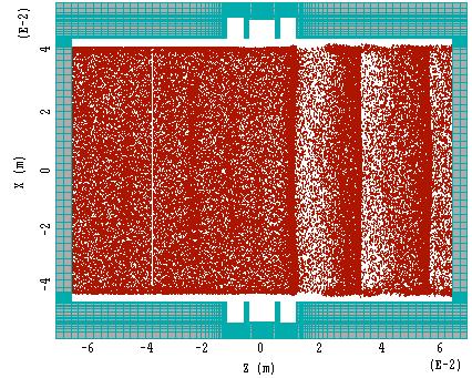
3 These are twin 5-cavity klystrons, with all cavities of the extended type operating in the - mode. The paper design consisted of a number of simulations and some cold testing. We wished to verify the following go, no-go conditions: 1. A gun can be designed with the necessary convergence and a low cathode current density. 2. The beam is well behaved and does not spread excessively laterally. 3. Cavities with sufficiently good R/Q and coupling coefficient can be designed, and provide a reasonably uniform field across the beam. 4. The klystron has good gain and efficiency. 5. The cavities are free of monotron oscillations for TM modes. These were the conditions that had to be satisfied before prototype construction is attempted. Results are shown in the figures that follow. Fig Figure 3 shows a MAGIC 3D simulation of a gun which provides a beam 8-mm thick, 8-cm wide, with a beam current density of 50 A/cm 2, and an area convergence of 10, i.e. a cathode current density of 5 A/cm 2. The cathode surface is elliptical for good optics. 2. Lateral gun electrodes have not been designed as yet, but Fig. 4 shows that a beam artificially injected in the drift tunnel and immersed in a 3000 magnetic field is not spreading in a 10-cm distance and remains evenly distributed along its width. PPM simulations have not been performed as of yet, but PPM focusing is not expected to be a problem. 3. The cavities for the DSBK were at first designed as single cutoff waveguides. This is the method proposed at SLAC more than 15 years ago for providing a flat electric field across the width of the beam. A cold test model was constructed to test this scheme, as well as the isolation between cavities separated by varying lengths of a 1.2 x 9 cm drift tunnel (Fig.5) Cavity isolation was found to be more than 50 db in 5 cm of drift tube. However, GdfidL and MAGIC calculations showed that the coupling coefficient and R/Q were too low for a single cavity of the cutoff waveguide type. Figure 6 shows that the coupling coefficient for a transit angle of about 1 radian was only Using triplet cutoff waveguides coupled capacitively
 are a printer artifact. Fig. 4 4. With two of these cavities and an artificial beam, a MAGIC calculation produced a gain of about 18 db between two triplets spaced about 30 cm apart.")

4 through the drift tube and operating in the mode corrected this. The coupling coefficient increased to 0.36 with an R/Q of 52 ohms. The light spots in the middle of the top view of the beam (Fig. 4) are a printer artifact. Fig With two of these cavities and an artificial beam, a MAGIC calculation produced a gain of about 18 db between two triplets spaced about 30 cm apart. Figure 7 shows the ratio of the rf current induced in the second cavity to the artificial rf current in the beam exciting the first cavity. We have inferred from these simulations the reduced plasma wavelength and beam loading parameters necessary to calculate small-signal gain. Using these in a standard gain vs. frequency calculation, we predict a 68+ db gain for the 5-cavity tube (Fig. 8 is on a separate page). Finally, a large-signal 3D-MAGIC simulation (Fig. 9) was run in which a beam modulated with an I 1 /I 0 of 1 drives a triplet. The figure shows normal debunching, and Figure 10 indicates that this is evenly distributed across the width of the beam. A simulation for a higher value of I 1 /Io will follow. Fig. 5
5 Single Cavity M = Ez 1.5E E E E+00 Ez Ez*Cosine Integral{Ez*dz} Integral{Ez*Cosine*dz} SBK Field Profile 4.5E E E E+00 Integral{Ez.dz} -5.0E E E E Z Triple Cavity M = Ez Ez*Cosine Integral{ Ez *dz} Integral{Ez*Cosine*dz} SBK Field Profile Ez Integral{Ez.dz} Z Fig. 6 Fig. 7. RF current vs. Z.

6 Fig. 9 Fig. 10
7 a b Io 320 f w 0.08 Brillouin field Data Inputs GPSDRV02.MCD Vo Beam Voltage (V) γ a = Beam resistance Plasma Frequency (rad/s) One-half of an 11.4 GHz 150-MW DSBK (Coupling coefficient from GdfidL, beam loading, reduced plasma frequency from MAGIC) Beam Current (A) Center Frequency (GHz) Drift tunnel half-height (meters) Beam half-thickness (meters) Beam width (meters) γ b = Ro = Bbr = Gauss ohms ωp = Vo Ro := Io Gun Microperveance (ua/v^1.5) Beam current dens. A/cm^2 Electron Prop. Constant (rad/m) Radial propagation constant (rad/m) γ = Bunching wave number (rad/m) Gap transit angle 100 No of cavities: Jo = 50 K = 1.06 βe = βq = βe d 1 = N 5 GAIN (DB) vs FREQUENCY PPmax P3 2 γ a S := b b = S = 1.5 R π f ωq = log( P s ) fo s λq = meters λp = meters Power 50% total efficiency: 0.5 Vo Io 10 9 = Cavity Rs/Q External Q and Qo GW Cavity Frequency (GHz) Gain Gap-Gap L (m) PPmax= Db RQ Qe Qo f l RQ Qe Qo f l RQ Qe Qo f l RQ Qe 4 Qo f l RQ Qe Qo f l Data Output Beam loaded Q Gap Distance Coupling Coefficient Drift Length (m) (induced current) (degrees) Qb Zg 1 = 0 M 1 = βql 1 = 0 Qb Zg 2 = 0.1 M 2 = βql 2 = Qb Zg 3 = 0.2 M 3 = βql 3 = Qb Zg 4 = 0.3 M 4 = βql 4 = Qb Zg 5 = 0.4 Fig. 8 M 5 = βql 5 =
8 7 Mode Number for Beam Width N=4, +++ mode "+ + +" "+ 0 -" "+ - +" Frequency [GHz] N "+ + +" "+ 0 -" "+ - +" Fig To test for stability in unloaded triplet cavities, a mode search was conducted using MAGIC (Fig. 11), and several of the TM modes were tested for negative beam loading, using GdfidL and the M 2 minus Mplus 2 criterion, the difference between the squares of the coupling coefficients for the fast and the slow space charge waves. (See Fig. 12). The slight differences in the frequencies between Fig. 12 and mode search and the stability tests in Fig. 12, are due to the fact that the structure used in Fig. 12, was tuned at GHz, instead of GHz.
9 Beam Coupling pi-mode βe. 2 Mminus i i 8. βq Mplus i Vb i mode N=0 and 2, and βe. 2 Mminus i i 8. βq Mplus i Vb i +++ mode N=4, βe. 2 Mminus i i 8. βq Mplus i Vb i Fig. 12 Stability test examples
10 CONCLUSIONS Although additional simulations will be necessary, it is clear the device has an excellent chance to work and should be built. This may take place in 2002.

11 APPENDIX 1 LATE BREAKING RESULTS FROM MRC Some recent results arrived from MRC which were too late to incorporate into the body of the paper, but too important to leave out. The first transmission from Dave Smithe of MRC, who was asked to drive a triplet cavity with a fully pre-bunched beam, is reproduced here without comment except to note that this is the first effort to run the simulation for full power. No attempts have been made to tune or otherwise adjust for maximum power. A.1.1 OUTPUT POWER Geometry: Resistive load filling each of the end cells. Beam voltage = 450 kv, Beam current = 320 amps, I 1 /I 0 = 1.8. Output Power: 62.0 MWatts, Wall Losses: 5.5 MWatts A top view of the cavity geometry is shown in Fig. A There is resistive load in each of the end cells. Fig. A A pre-bunched beam is injected into the cavity, and it is rung up to saturation. Many runs were done to optimize the output power by varying the amount of resistance (cavity Q), and hot-test frequency-shift (+0.01%). The following figure (A.1.1.2) shows the time-history of cavity saturation. The first plot shows the sum of power to the end-cell load plus wall-losses, and the second plot shows just wall-losses. Load + Wall Losses Just Wall Losses Fig. A.1.1.2


12 A view of the particles and current is shown below (Fig. A.1.1.3). The shape of the pre-bunched current is a sine wave, truncated below some value, and re-scaled to give the correct DC current. The particles are injected at a single energy of 450 kv. Fig. A.1.1.3

13 Shown below are views of particle-energy, average-energy-per-particle, and RF-current, down the length of the drift tube (Fig. A.1.1.4). Note that few, if any, particles are turned-around. About 47% of the original beam energy is lost, 43% to the output load, and 4% to copper wall losses. The RF current at the exit is about _ of the original pre-bunched RF current. Particle Energy Average Particle Energy RF Currrent Fig. A.1.1.4


14 A.1.2 TEST OF CAVITY STABILITY This is a final transmission from MRC (Fig. A.1.2.1). The objective here was to completely unbalance the beam to see whether modes might be excited in the cavity that would lead to oscillations. It can be seen from the treatment below that this did not happen. Geometry: Unloaded, copper cavity. Used _ of beam, e.g., missing right and lower halves, with no RF signal, other than the initial transient. The offset beam and the initial transient provide the seed for any unstable modes. The beam current density is the save as for the previous 450 kv, 320 amp runs. Fig. A.1.2.1
15 From previous simulations, it is already known that the system is stable at the operating mode, as the operating mode has been to seen to saturate in a conventional manner during small-signal analysis. The simulation was run for 80 nanoseconds. Any linear instability would exhibit an exponential increase in the electromagnetic energy (U em = _ε E 2 + _µ H 2 ) stored within the cavity, as the instability mode grew in amplitude. No such increase was observed. The offset beam, in both X and Y directions, should couple strongly to virtually all conceivable modes, thus there is little chance that an instability exists, but is undetected, since the instability seed is quite strong. Wall losses of copper have been included. Thus it is still possible that a perfectly conducting cavity might experience an instability, but that the copper wall-loss loaded system is stable. Instead of an exponential rise in EM energy, a very slow, approximately linear, growth in electromagnetic energy was observed (Fig. A.1.2.2). This is typical of all unfiltered relativistic particle-in-cell simulations and is associated with growth of short-wavelength (grid-size) particle noise in a simulation. There is no identifiable cavity mode structure associated with particle noise (Fig. A.1.2.3). EM Energy in Cavity Fig. A There is also no evidence of a coherent RF signal on the particle positions or energy after 80 nanoseconds.


16 Fig. A This result is for a single cavity. Instability associated with power propagation between two or more triple-cavities separated by rectangular drift tube has not been investigated here.
17 ACKNOWLEDGEMENTS Thanks are due to Daryl Sprehn, who developed the gun optics, Mike Neubauer for the GdifdL simulations, David Smithe of MRC who performed the MAGIC simulations, and Randy Fowkes for the cold test work.
5 th Modulator Klystron Workshop MDK2001. Session 1-2 Chairman : G. Caryotakis (SLAC) Klystron Technology
 Klystron Technology") 5 th Modulator Klystron Workshop MDK2001 Session 1-2 Chairman : G. Caryotakis (SLAC) Klystron Technology REVIEW OF SESSION 1.2 KLYSTRON TECHNOLOGY G. Caryotakis (Chairman) SLAC These were 4 completely
5 th Modulator Klystron Workshop MDK2001 Session 1-2 Chairman : G. Caryotakis (SLAC) Klystron Technology REVIEW OF SESSION 1.2 KLYSTRON TECHNOLOGY G. Caryotakis (Chairman) SLAC These were 4 completely
DEVELOPMENT OF X-BAND KLYSTRON TECHNOLOGY AT SLAC
 DEVELOPMENT OF X-BAND KLYSTRON TECHNOLOGY AT SLAC George Caryotakis, Stanford Linear Accelerator Center P.O. Box 4349 Stanford, CA 94309 Abstract * The SLAC design for a 1-TeV collider (NLC) requires klystrons
A HIGH POWER LONG PULSE HIGH EFFICIENCY MULTI BEAM KLYSTRON
 A HIGH POWER LONG PULSE HIGH EFFICIENCY MULTI BEAM KLYSTRON A.Beunas and G. Faillon Thales Electron Devices, Vélizy, France S. Choroba DESY, Hamburg, Germany Abstract THALES ELECTRON DEVICES has developed
Development of Multiple Beam Guns for High Power RF Sources for Accelerators and Colliders
 SLAC-PUB-10704 Development of Multiple Beam Guns for High Power RF Sources for Accelerators and Colliders R. Lawrence Ives*, George Miram*, Anatoly Krasnykh @, Valentin Ivanov @, David Marsden*, Max Mizuhara*,
DEVELOPMENT OF A 10 MW SHEET BEAM KLYSTRON FOR THE ILC*
 DEVELOPMENT OF A 10 MW SHEET BEAM KLYSTRON FOR THE ILC* D. Sprehn, E. Jongewaard, A. Haase, A. Jensen, D. Martin, SLAC National Accelerator Laboratory, Menlo Park, CA 94020, U.S.A. A. Burke, SAIC, San
Detailed Design Report
 Detailed Design Report Chapter 4 MAX IV Injector 4.6. Acceleration MAX IV Facility CHAPTER 4.6. ACCELERATION 1(10) 4.6. Acceleration 4.6. Acceleration...2 4.6.1. RF Units... 2 4.6.2. Accelerator Units...
X-Band Klystron Development at
 X-Band Klystron Development at SLAC Slide 1 The Beginning X-band klystron work began at SLAC in the mid to late 80 s to develop high frequency (4x SLAC s-band), high power RF sources for the linear collider
NEW METHOD FOR KLYSTRON MODELING
 NEW METHOD FOR KLYSTRON MODELING Y. H. Chin, KEK, 1-1 Oho, Tsukuba-shi, Ibaraki-ken, 35, Japan Abstract We have developed a new method for a realistic and more accurate simulation of klystron using the
INFN School on Electron Accelerators. RF Power Sources and Distribution
 INFN School on Electron Accelerators 12-14 September 2007, INFN Sezione di Pisa Lecture 7b RF Power Sources and Distribution Carlo Pagani University of Milano INFN Milano-LASA & GDE The ILC Double Tunnel
RF Power Generation II
 RF Power Generation II Klystrons, Magnetrons and Gyrotrons Professor R.G. Carter Engineering Department, Lancaster University, U.K. and The Cockcroft Institute of Accelerator Science and Technology Scope
DESIGN AND PERFORMANCE OF L-BAND AND S-BAND MULTI BEAM KLYSTRONS
 DESIGN AND PERFORMANCE OF L-BAND AND S-BAND MULTI BEAM KLYSTRONS Y. H. Chin, KEK, Tsukuba, Japan. Abstract Recently, there has been a rising international interest in multi-beam klystrons (MBK) in the
These tests will be repeated for different anode positions. Radiofrequency interaction measurements will be made subsequently. A.
 VI. MICROWAVE ELECTRONICS Prof. L. D. Smullin Prof. L. J. Chu A. Poeltinger Prof. H. A. Haus L. C. Bahiana C. W. Rook, Jr. Prof. A. Bers R. J. Briggs J. J. Uebbing D. Parker A. HIGH-PERVEANCE HOLLOW ELECTRON-BEAM
INTERNATIONAL JOURNAL OF ELECTRONICS AND COMMUNICATION ENGINEERING & TECHNOLOGY (IJECET)
") INTERNATIONAL JOURNAL OF ELECTRONICS AND COMMUNICATION ENGINEERING & TECHNOLOGY (IJECET) International Journal of Electronics and Communication Engineering & Technology (IJECET), ISSN 0976 6464(Print)
INTERNATIONAL JOURNAL OF ELECTRONICS AND COMMUNICATION ENGINEERING & TECHNOLOGY (IJECET) International Journal of Electronics and Communication Engineering & Technology (IJECET), ISSN 0976 6464(Print)
THE NEXT LINEAR COLLIDER TEST ACCELERATOR: STATUS AND RESULTS * Abstract
 SLAC PUB 7246 June 996 THE NEXT LINEAR COLLIDER TEST ACCELERATOR: STATUS AND RESULTS * Ronald D. Ruth, SLAC, Stanford, CA, USA Abstract At SLAC, we are pursuing the design of a Next Linear Collider (NLC)
Development of klystrons with ultimately high - 90% RF power production efficiency
 Development of klystrons with ultimately high - 90% RF power production efficiency A. Baikov (MUFA), I. Syratchev (CERN), C. Lingwood, D. Constable (Lancaster University) Introduction FCC has high power
4.4 Injector Linear Accelerator
 4.4 Injector Linear Accelerator 100 MeV S-band linear accelerator based on the components already built for the S-Band Linear Collider Test Facility at DESY [1, 2] will be used as an injector for the CANDLE
THE X-BAND KLYSTRON PROGRAM AT SLAC'
 SLAC-PUB-7 146 April 1996 THE X-BAND KLYSTRON PROGRAM AT SLAC' George Caryotakis ' Stanford Linear Accelerator Center Stanford University, Stanford, CA 9439 The X-band r f source development at SLAC can
Pulsed Klystrons for Next Generation Neutron Sources Edward L. Eisen - CPI, Inc. Palo Alto, CA, USA
 Pulsed Klystrons for Next Generation Neutron Sources Edward L. Eisen - CPI, Inc. Palo Alto, CA, USA Abstract The U.S. Department of Energy (DOE) Office of Science has funded the construction of a new accelerator-based
45 MW, 22.8 GHz Second-Harmonic Multiplier for High-Gradient Tests*
 US High Gradient Research Collaboration Workshop. SLAC, May 23-25, 2007 45 MW, 22.8 GHz Second-Harmonic Multiplier for High-Gradient Tests* V.P. Yakovlev 1, S.Yu. Kazakov 1,2, and J.L. Hirshfield 1,3 1
KLYSTRON GUN ARCING AND MODULATOR PROTECTION
 SLAC-PUB-10435 KLYSTRON GUN ARCING AND MODULATOR PROTECTION S.L. Gold Stanford Linear Accelerator Center (SLAC), Menlo Park, CA USA Abstract The demand for 500 kv and 265 amperes peak to power an X-Band
Lecture 17 Microwave Tubes: Part I
 Basic Building Blocks of Microwave Engineering Prof. Amitabha Bhattacharya Department of Electronics and Communication Engineering Indian Institute of Technology, Kharagpur Lecture 17 Microwave Tubes:
150-MW S-Band Klystron Program at the Stanford Linear Accelerator Center1
 SLAC Pub 7232 July 1996 4 15-MW S-Band Klystron Program at the Stanford Linear Accelerator Center1 D. SPREHN, G. CARYOTAKS, and R. M. PHLLPS Stanford Linear Accelerator Center Stanford Universiw, Stanford,
Evaluation of Performance, Reliability, and Risk for High Peak Power RF Sources from S-band through X-band for Advanced Accelerator Applications
 Evaluation of Performance, Reliability, and Risk for High Peak Power RF Sources from S-band through X-band for Advanced Accelerator Applications Michael V. Fazio C. Adolphsen, A. Jensen, C. Pearson, D.
PEP-I1 RF Feedback System Simulation
 SLAC-PUB-10378 PEP-I1 RF Feedback System Simulation Richard Tighe SLAC A model containing the fundamental impedance of the PEP- = I1 cavity along with the longitudinal beam dynamics and feedback system
This work was supported by FINEP (Research and Projects Financing) under contract
 under contract") MODELING OF A GRIDDED ELECTRON GUN FOR TRAVELING WAVE TUBES C. C. Xavier and C. C. Motta Nuclear & Energetic Research Institute, São Paulo, SP, Brazil University of São Paulo, São Paulo, SP, Brazil Abstract
MODELING OF A GRIDDED ELECTRON GUN FOR TRAVELING WAVE TUBES C. C. Xavier and C. C. Motta Nuclear & Energetic Research Institute, São Paulo, SP, Brazil University of São Paulo, São Paulo, SP, Brazil Abstract
Tutorial: Trak design of an electron injector for a coupled-cavity linear accelerator
 Tutorial: Trak design of an electron injector for a coupled-cavity linear accelerator Stanley Humphries, Copyright 2012 Field Precision PO Box 13595, Albuquerque, NM 87192 U.S.A. Telephone: +1-505-220-3975
Design and Simulation of High Power RF Modulated Triode Electron Gun. A. Poursaleh
 Design and Simulation of High Power RF Modulated Triode Electron Gun A. Poursaleh National Academy of Sciences of Armenia, Institute of Radio Physics & Electronics, Yerevan, Armenia poursaleh83@yahoo.com
RF POWER GENERATION FOR FUTURE LINEAR COLLIDERS* 1. Introduction
 SLAC-PUB-5282 June 1990 (A) RF POWER GENERATION FOR FUTURE LINEAR COLLIDERS* W. R. Fowkes, M. A. Allen, R. S. Callin, G. Caryotakis, K. R. Eppley, K. S. Fant, Z. D. Farkas, J. Feinstein, K. Ko, R. F. Koontz,
Design of a 50 MW Klystron at X-Band*
 SLAC-PUB-954676 July 1995 Background Eight Next Linear Collider (NLC) prototype klystrons, known as the XC-series Design of a 50 MW Klystron at X-Band* klystrons, have been evaluated at SLAC with a goal
UNIT-3 Part A. 2. What is radio sonde? [ N/D-16]
![UNIT-3 Part A. 2. What is radio sonde? [ N/D-16]](/thumbs/88/116973079.jpg "UNIT-3 Part A. 2. What is radio sonde? [ N/D-16]") UNIT-3 Part A 1. What is CFAR loss? [ N/D-16] Constant false alarm rate (CFAR) is a property of threshold or gain control devices that maintain an approximately constant rate of false target detections
UNIT-3 Part A 1. What is CFAR loss? [ N/D-16] Constant false alarm rate (CFAR) is a property of threshold or gain control devices that maintain an approximately constant rate of false target detections
IOT RF Power Sources for Pulsed and CW Linacs
 LINAC 2004 Lübeck, August 16 20, 2004 IOT RF Power Sources H. Bohlen, Y. Li, Bob Tornoe Communications & Power Industries Eimac Division, San Carlos, CA, USA Linac RF source property requirements (not
LASERTRON SIMULATION WITH A TWO-GAP OUTPUT CAVITY*
 SLAC/AP-41 April 1985 CAP) LASERTRON SMULATON WTH A TWO-GAP OUTPUT CAVTY* W. B. Herrmannsfeldt Stanford Linear Accelerator Center Stanford University, Stanford, California 94305 Abstract: With a two-gap
ADVANCED HIGH-POWER MICROWAVE VACUUM ELECTRON DEVICE DEVELOPMENT
 ADVANCED HIGH-POWER MICROWAVE VACUUM ELECTRON DEVICE DEVELOPMENT H. P. Bohlen, Inc., Palo Alto, CA Abstract The microwave 1 power requirements of particle accelerators have been growing almost exponentially
Design, Fabrication and Testing of Gun-Collector Test Module for 6 MW Peak, 24 kw Average Power, S-Band Klystron
 Available online www.ejaet.com European Journal of Advances in Engineering and Technology, 2014, 1(1): 11-15 Research Article ISSN: 2394-658X Design, Fabrication and Testing of Gun-Collector Test Module
Experience with the Cornell ERL Injector SRF Cryomodule during High Beam Current Operation
 Experience with the Cornell ERL Injector SRF Cryomodule during High Beam Current Operation Matthias Liepe Assistant Professor of Physics Cornell University Experience with the Cornell ERL Injector SRF
* Work supported by Department of Energy contract DE-AC03-76SF RF Pulse Compression. for F'uture Linear Colliders* SLAC-PUB
 SLAC-PUB-95-6755 RF Pulse Compression for F'uture Linear Colliders* PERRY B. WILSON Stanford Linear Accelerator Center Stanford University, Stanford, CA 94309 Presented at the Conference on Pulsed RF Sources
X-Band klystron development at the Stanford Linear Accelerator Center
 SLAC-PUB-8346 March 2000 X-Band klystron development at the Stanford Linear Accelerator Center D. Sprehn, G. Caryotakis, E. Jongewaard, R. M. Phillips, and A. Vlieks Stanford Linear Accelerator Center
The Elettra Storage Ring and Top-Up Operation
 The Elettra Storage Ring and Top-Up Operation Emanuel Karantzoulis Past and Present Configurations 1994-2007 From 2008 5000 hours /year to the users 2010: Operations transition year Decay mode, 2 GeV (340mA)
DESIGN AND TECHNOLOGICAL ASPECTS OF KLYSTRON DEVELOPMENT
 DESIGN AND TECHNOLOGICAL ASPECTS OF KLYSTRON DEVELOPMENT Dr. L M Joshi Emeritus Scientist CSIR-CEERI, PILANI lmj1953@gmail.com 22 February 2017 IPR 1 Schemetic Diagram 22 February 2017 IPR 2 Basic Principle
Final Report. U.S. Department of Energy Grant Number DE-FG02-04ER83916
 Development of a 200 MHz Multiple Beam Klystron Final Report U.S. Department of Energy Grant Number DE-FG02-04ER83916 July 2004 - March 2005 Calabazas Creek Research, Inc. 20937 Comer Drive Saratoga, CA
Klystron Tubes. Two forms of such a device, also called linear beam klystron, are given in the following figure.
 Klystron Tubes Go to the klystron index The principle of velocity-variation, first used in Heil oscillators, was also used in other microwave amplifying and oscillating tubes. The application for klystron
Effect on Beam Current on varying the parameters of BFE and Control Anode of a TWT Electron Gun
 International Journal of Photonics. ISSN 0974-2212 Volume 7, Number 1 (2015), pp. 1-9 International Research Publication House http://www.irphouse.com Effect on Beam Current on varying the parameters of
RF considerations for SwissFEL
 RF considerations for H. Fitze in behalf of the PSI RF group Workshop on Compact X-Ray Free Electron Lasers 19.-21. July 2010, Shanghai Agenda Introduction RF-Gun Development C-band development Summary
Pseudospark-sourced Micro-sized Electron Beams for High Frequency klystron Applications
 Pseudospark-sourced Micro-sized Electron Beams for High Frequency klystron Applications H. Yin 1*, D. Bowes 1, A.W. Cross 1, W. He 1, K. Ronald 1, A. D. R. Phelps 1, D. Li 2 and X. Chen 2 1 SUPA, Department
Design Studies For The LCLS 120 Hz RF Gun Injector
 BNL-67922 Informal Report LCLS-TN-01-3 Design Studies For The LCLS 120 Hz RF Gun Injector X.J. Wang, M. Babzien, I. Ben-Zvi, X.Y. Chang, S. Pjerov, and M. Woodle National Synchrotron Light Source Brookhaven
SLAC-PUB-2380 August 1979 (A)
") 1979 LINEAR ACCELERATOR CONFERENCE RF SOURCES DEVELOPMENTS* Jean V. Lebacqz Stanford Linear Accelerator Center Stanford University, Stanford, California 94305 SLAC-PUB-2380 August 1979 (A) Abstract The
1979 LINEAR ACCELERATOR CONFERENCE RF SOURCES DEVELOPMENTS* Jean V. Lebacqz Stanford Linear Accelerator Center Stanford University, Stanford, California 94305 SLAC-PUB-2380 August 1979 (A) Abstract The
TECHNICAL SPECIFICATION Multi-beam S-band Klystron type BT267
 TECHNICAL SPECIFICATION Multi-beam S-band Klystron type BT267 The company was created for the development and manufacture of precision microwave vacuum-electron-tube devices (VETD). The main product areas
Solid State Modulators for X-Band Accelerators
 Solid State Modulators for X-Band Accelerators John Kinross-Wright Diversified Technologies, Inc. Bedford, Massachusetts DTI X-Band Experience Developed and built two completely different NLC-class modulator
Development of an Abort Gap Monitor for High-Energy Proton Rings *
 Development of an Abort Gap Monitor for High-Energy Proton Rings * J.-F. Beche, J. Byrd, S. De Santis, P. Denes, M. Placidi, W. Turner, M. Zolotorev Lawrence Berkeley National Laboratory, Berkeley, USA
w. B. HERRMANNSFELDT and K. R. EPPLEY
 Particle Accelerators, 199, Vol. 3, pp. 197-29 Reprints available directly from the publisher Photocopying permitted by license only 199 Gordon and Breach, Science Publishers, Inc. Printed in the United
STATUS OF THE SWISSFEL C-BAND LINEAR ACCELERATOR
 Proceedings of FEL213, New York, NY, USA STATUS OF THE SWISSFEL C-BAND LINEAR ACCELERATOR F. Loehl, J. Alex, H. Blumer, M. Bopp, H. Braun, A. Citterio, U. Ellenberger, H. Fitze, H. Joehri, T. Kleeb, L.
650MHz/800kW Klystron Development at IHEP
 650MHz/800kW Klystron Development at IHEP Shilun Pei, IHEP On behalf of HERSC (High Efficiency RF Source R&D Collaboration) in China Presentation at the IAS Program on High Energy Physics January 22, 2018,
Development of High Power Vacuum Tubes for Accelerators and Plasma Heating
 Development of High Power Vacuum Tubes for Accelerators and Plasma Heating Vishnu Srivastava Microwave Tubes Division, CSIR-Central Electronics Engineering Research Institute, Pilani-333031, Rajasthan,
!"!3
 Abstract A single-mode 500 MHz superconducting cavity cryomodule has been developed at Cornell for the electronpositron collider/synchrotron light source CESR. The Cornell B-cell cavity belongs to the
Low Frequency Gyrotrons for Fusion
 13th Joint Workshop on Electron Cyclotron Emission and Electron Cyclotron Resonance Heating Nizhny Novgorod, Russia May 17-20, 2004 РАН Low Frequency Gyrotrons for Fusion НПП ГИКОМ V.E. Zapevalov, Yu.K.
Next Linear Collider. The 8-Pack Project. 8-Pack Project. Four 50 MW XL4 X-band klystrons installed on the 8-Pack
 The Four 50 MW XL4 X-band klystrons installed on the 8-Pack The Demonstrate an NLC power source Two Phases: 8-Pack Phase-1 (current): Multi-moded SLED II power compression Produce NLC baseline power: 475
reported by T. Shintake KEK / RIKEN Japan Summary of C-band R&D for Linear Collider at KEK New soft-x-ray FEL Project at RIKEN/SPring-8
 C-band RF System R&D reported by T. Shintake KEK / RIKEN Japan Summary of C-band R&D for Linear Collider at KEK New soft-x-ray FEL Project at RIKEN/SPring-8 Project was funded in 2001 April Material Science
SLAC R&D Program for a Polarized RF Gun
 ILC @ SLAC R&D Program for a Polarized RF Gun SLAC-PUB-11657 January 2006 (A) J. E. CLENDENIN, A. BRACHMANN, D. H. DOWELL, E. L. GARWIN, K. IOAKEIMIDI, R. E. KIRBY, T. MARUYAMA, R. A. MILLER, C. Y. PRESCOTT,
RF Solutions for Science.
 RF Solutions for Science www.thalesgroup.com State-of-the-art RF sources for your scientific needs High-power klystrons HIGH KLYSTRONS WITH RF LONG PULSE above 50 μs Thales has been one of the leading
CPI Gyrotrons For Fusion EC Heating
 CPI Gyrotrons For Fusion EC Heating H. Jory, M. Blank, P. Borchard, P. Cahalan, S. Cauffman, T. S. Chu, and K. Felch CPI, Microwave Power Products Division 811 Hansen Way, Palo Alto, CA 94303, USA e-mail:
TEST RESULTS OF THE 84 GHZ / 200 KW / CW GYROTRON
 TEST RESULTS OF THE 84 GHZ / 200 KW / CW GYROTRON V.I. Belousov, A.A.Bogdashov, G.G.Denisov, V.I.Kurbatov, V.I.Malygin, S.A.Malygin, V.B.Orlov, L.G.Popov, E.A.Solujanova, E.M.Tai, S.V.Usachov Gycom Ltd,
CERN EUROPEAN ORGANIZATION FOR NUCLEAR RESEARCH. A 50 Hz LOW-POWER SOLID-STATE KLYSTRON-MODULATOR
 CERN EUROPEAN ORGANIZATION FOR NUCLEAR REEARCH CTF3 Note 051(Tech.) (IGCT witch) A 50 Hz LOW-POWER OLID-TATE KLYTRON-MODULATOR P. Pearce, L. ermeus, L. hen Abstract A solid-state klystron-modulator has
North Damping Ring RF
 North Damping Ring RF North Damping Ring RF Outline Overview High Power RF HVPS Klystron & Klystron EPICS controls Cavities & Cavity Feedback SCP diagnostics & displays FACET-specific LLRF LLRF distribution
Recent ITER-Relevant Gyrotron Tests
 Journal of Physics: Conference Series Recent ITER-Relevant Gyrotron Tests To cite this article: K Felch et al 2005 J. Phys.: Conf. Ser. 25 13 View the article online for updates and enhancements. Related
CEPC Klystron Development
 CEPC Klystron Development Zusheng Zhou On behalf of High Efficiency RF Source R&D Collaboration Institute of High Energy Physics Sep. 26, 2018, HKUST, Hong Kong 1 Outline Strategy and plan 650MHz/800kW
J/NLC Progress on R1 and R2 Issues. Chris Adolphsen
 J/NLC Progress on R1 and R2 Issues Chris Adolphsen Charge to the International Linear Collider Technical Review Committee (ILC-TRC) To assess the present technical status of the four LC designs at hand,
Oak Ridge Spallation Neutron Source Proton Power Upgrade Project and Second Target Station Project
 Oak Ridge Spallation Neutron Source Proton Power Upgrade Project and Second Target Station Project Workshop on the future and next generation capabilities of accelerator driven neutron and muon sources
Dark current and multipacting trajectories simulations for the RF Photo Gun at PITZ
 Dark current and multipacting trajectories simulations for the RF Photo Gun at PITZ Introduction The PITZ RF Photo Gun Field simulations Dark current simulations Multipacting simulations Summary Igor Isaev
High Brightness Injector Development and ERL Planning at Cornell. Charlie Sinclair Cornell University Laboratory for Elementary-Particle Physics
 High Brightness Injector Development and ERL Planning at Cornell Charlie Sinclair Cornell University Laboratory for Elementary-Particle Physics June 22, 2006 JLab CASA Seminar 2 Background During 2000-2001,
IOT OPERATIONAL EXPERIENCE ON ALICE AND EMMA AT DARESBURY LABORATORY
 IOT OPERATIONAL EXPERIENCE ON ALICE AND EMMA AT DARESBURY LABORATORY A. Wheelhouse ASTeC, STFC Daresbury Laboratory ESLS XVIII Workshop, ELLETRA 25 th 26 th November 2010 Contents Brief Description ALICE
Activities on FEL Development and Application at Kyoto University
 Activities on FEL Development and Application at Kyoto University China-Korea-Japan Joint Workshop on Electron / Photon Sources and Applications Dec. 2-3, 2010 @ SINAP, Shanghai Kai Masuda Inst. Advanced
RF plans for ESS. Morten Jensen. ESLS-RF 2013 Berlin
 RF plans for ESS Morten Jensen ESLS-RF 2013 Berlin Overview The European Spallation Source (ESS) will house the most powerful proton linac ever built. The average beam power will be 5 MW which is five
Empirical Model For ESS Klystron Cathode Voltage
 Empirical Model For ESS Klystron Cathode Voltage Dave McGinnis 2 March 2012 Introduction There are 176 klystrons in the superconducting portion of ESS linac. The power range required spans a factor of
18 GHz, 2.2 kw KLYSTRON GENERATOR GKP 24KP 18GHz WR62 3x400V
 18 GHz, 2.2 kw KLYSTRON GENERATOR GKP 24KP 18GHz WR62 3x400V With its characteristics of power stability whatever the load, very fast response time when pulsed (via external modulated signal), low ripple,
Current status of XFEL/SPring-8 project and SCSS test accelerator
 Current status of XFEL/SPring-8 project and SCSS test accelerator Takahiro Inagaki for XFEL project in SPring-8 inagaki@spring8.or.jp Outline (1) Introduction (2) Key technology for compactness (3) Key
Towards an X-Band Power Source at CERN and a European Structure Test Facility
 Towards an X-Band Power Source at CERN and a European Structure Test Facility Erk Jensen and Gerry McMomagle CERN The X-Band Accelerating Structure Design and Test-Program Workshop Day 2: Structure Testing
Electrical and Electronic Laboratory Faculty of Engineering Chulalongkorn University. Cathode-Ray Oscilloscope (CRO)
") 2141274 Electrical and Electronic Laboratory Faculty of Engineering Chulalongkorn University Cathode-Ray Oscilloscope (CRO) Objectives You will be able to use an oscilloscope to measure voltage, frequency
2141274 Electrical and Electronic Laboratory Faculty of Engineering Chulalongkorn University Cathode-Ray Oscilloscope (CRO) Objectives You will be able to use an oscilloscope to measure voltage, frequency
ILC-LNF TECHNICAL NOTE
 IL-LNF EHNIAL NOE Divisione Acceleratori Frascati, July 4, 2006 Note: IL-LNF-001 RF SYSEM FOR HE IL DAMPING RINGS R. Boni, INFN-LNF, Frascati, Italy G. avallari, ERN, Geneva, Switzerland Introduction For
3 cerl. 3-1 cerl Overview. 3-2 High-brightness DC Photocathode Gun and Gun Test Beamline
 3 cerl 3-1 cerl Overview As described before, the aim of the cerl in the R&D program includes the development of critical components for the ERL, as well as the construction of a test accelerator. The
Available online Journal of Scientific and Engineering Research, 2018, 5(5): Research Article
: Research Article") Available online www.jsaer.com, 218, 5(5):247-251 Research Article ISSN: 2394-263 CODEN(USA): JSERBR Optimization of Klystron Cavity Using Dielectric Materials Digima Mustapha 1 *, Ibrahim Mustapha 2,
Available online www.jsaer.com, 218, 5(5):247-251 Research Article ISSN: 2394-263 CODEN(USA): JSERBR Optimization of Klystron Cavity Using Dielectric Materials Digima Mustapha 1 *, Ibrahim Mustapha 2,
RECENT PROGRESS IN UPGRADE OF THE HIGH INTENSITY THzzz zz-fel AT OzSAKzA UNIVERSITYzzzz
 RECENT PROGRESS IN UPGRADE OF THE HIGH INTENSITY THzzz zz-fel AT OzSAKzA UNIVERSITYzzzz G. Isoyama#, M. Fujimoto, S. Funakoshi, K. Furukawa, A. Irizawa, R. Kato, K. Kawase, A. Tokuchi, R. Tsutsumi, M.
PEP II Design Outline
 PEP II Design Outline Balša Terzić Jefferson Lab Collider Review Retreat, February 24, 2010 Outline General Information Parameter list (and evolution), initial design, upgrades Collider Ring Layout, insertions,
PULSED POWER FOR FUTURE LINEAR ACCELERATORS
 PULSED POWER FOR FUTURE LINEAR ACCELERATORS Peter D. Pearce High-energy accelerators High-energy accelerators enable us to collide particle beams together and create conditions believed to be similar to
Studies on an S-band bunching system with hybrid buncher
 Submitted to Chinese Physics C Studies on an S-band bunching system with hybrid buncher PEI Shi-Lun( 裴士伦 ) 1) XIAO Ou-Zheng( 肖欧正 ) Institute of High Energy Physics, Chinese Academy of Sciences, Beijing
2 Work Package and Work Unit descriptions. 2.8 WP8: RF Systems (R. Ruber, Uppsala)
") 2 Work Package and Work Unit descriptions 2.8 WP8: RF Systems (R. Ruber, Uppsala) The RF systems work package (WP) addresses the design and development of the RF power generation, control and distribution
2 Work Package and Work Unit descriptions 2.8 WP8: RF Systems (R. Ruber, Uppsala) The RF systems work package (WP) addresses the design and development of the RF power generation, control and distribution
New Results on the Electron Cloud at the Los Alamos PSR
 New Results on the Electron Cloud at the Los Alamos PSR Robert Macek, LANL, 4/15/02 Co-authors: A. Browman, D. Fitzgerald, R. McCrady, T. Spickermann, & T. S. Wang - LANL For more information see the website
Defense Technical Information Center Compilation Part Notice
 UNCLASSIFIED Defense Technical Information Center Compilation Part Notice ADPO1 1739 TITLE: Modelling of Micromachined Klystrons for Terahertz Operation DISTRIBUTION: Approved for public release, distribution
The FLASH objective: SASE between 60 and 13 nm
 Injector beam control studies winter 2006/07 talk from E. Vogel on work performed by W. Cichalewski, C. Gerth, W. Jalmuzna,W. Koprek, F. Löhl, D. Noelle, P. Pucyk, H. Schlarb, T. Traber, E. Vogel, FLASH
Spear3 RF System Sam Park 11/06/2003. Spear3 RF System. High Power Components Operation and Control. RF Requirement.
 Spear3 RF System RF Requirement Overall System High Power Components Operation and Control SPEAR 3 History 1996 Low emittance lattices explored 1996 SPEAR 3 proposed 11/97 SPEAR 3 design study team formed
A New 4MW LHCD System for EAST
 1 EXW/P7-29 A New 4MW LHCD System for EAST Jiafang SHAN 1), Yong YANG 1), Fukun LIU 1), Lianmin ZHAO 1) and LHCD Team 1) 1) Institute of Plasma Physics, Chinese Academy of Sciences, Hefei, China E-mail
Pulses inside the pulse mode of operation at RF Gun
 Pulses inside the pulse mode of operation at RF Gun V. Vogel, V. Ayvazyan, K. Floettmann, D. Lipka, P. Morozov, H. Schlarb, S. Schreiber FLASH Seminar, DESY March 29, 2011 Contents Why we need a PiPmode
Chris Gilmour Studies into the Design of a Higher Efficiency Ku Band ring-loop Travelling Wave Tube SWS using the CST PIC Software.
 Chris Gilmour Studies into the Design of a Higher Efficiency Ku Band ring-loop Travelling Wave Tube SWS using the CST PIC Software.... the power in microwaves! History TMD have been making ring-loop TWTs
RF Design of the LCLS Gun C.Limborg, Z.Li, L.Xiao, J.F. Schmerge, D.Dowell, S.Gierman, E.Bong, S.Gilevich February 9, 2005
 RF Design of the LCLS Gun C.Limborg, Z.Li, L.Xiao, J.F. Schmerge, D.Dowell, S.Gierman, E.Bong, S.Gilevich February 9, 2005 Summary Final dimensions for the LCLS RF gun are described. This gun, referred
KARA and FLUTE RF Overview/status
 KARA and FLUTE RF Overview/status Nigel Smale on behalf of IBPT and LAS teams Laboratory for Applications of Synchrotron radiation (LAS) Institute for Beam Physics and Technology (IBPT) KARA KIT The Research
Low-Noise, High-Efficiency and High-Quality Magnetron for Microwave Oven
 Low-Noise, High-Efficiency and High-Quality Magnetron for Microwave Oven N. Kuwahara 1*, T. Ishii 1, K. Hirayama 2, T. Mitani 2, N. Shinohara 2 1 Panasonic corporation, 2-3-1-3 Noji-higashi, Kusatsu City,
Accelerator Instrumentation RD. Monday, July 14, 2003 Marc Ross
 Monday, Marc Ross Linear Collider RD Most RD funds address the most serious cost driver energy The most serious impact of the late technology choice is the failure to adequately address luminosity RD issues
XFEL High Power RF System Recent Developments
 XFEL High Power RF System Recent Developments for the XFEL RF Group Outline XFEL RF System Requirements Overview Basic Layout RF System Main Components Multibeam Klystrons Modulator RF Waveguide Distribution
14 GHz, 2.2 kw KLYSTRON GENERATOR GKP 22KP 14GHz WR62 3x400V
 14 GHz, 2.2 kw KLYSTRON GENERATOR GKP 22KP 14GHz WR62 3x400V With its characteristics of power stability independent of the load, very fast response time when pulsed (via external modulated signal), low
A tapered multi-gap multi-aperture pseudospark-sourced electron gun based X-band slow wave oscillator
 A tapered multi-gap multi-aperture pseudospark-sourced electron gun based X-band slow wave oscillator N. Kumar 1, R. P. Lamba 1, A. M. Hossain 1, U. N. Pal 1, A. D. R. Phelps and R. Prakash 1 1 CSIR-CEERI,
Experimental Results of the Coaxial Multipactor Experiment. T.P. Graves, B. LaBombard, S.J. Wukitch, I.H. Hutchinson PSFC-MIT
 Experimental Results of the Coaxial Multipactor Experiment T.P. Graves, B. LaBombard, S.J. Wukitch, I.H. Hutchinson PSFC-MIT Summary A multipactor discharge is a resonant condition for electrons in an