Standard disclaimer: You do all these upgrades at your own risk to your car and your factory Audi warranty. Contributing Editor: Lee Hicks (NSX Jr)
|
|
|
- Clementine Holt
- 6 years ago
- Views:
Transcription
1 1a. TeddyBGame RNS-E install: 1)Slight modifications to plug/play adaptor 2)Upgrading the climate control faceplate to the color (optional activity) 3)Building plug/play adaptor for OEM SAT tuner and OEM Phatbox or Ipod IceLINK or Blitzsafe audio interface (optional activity) Please note: A majority of these pictures are applicable to a pre C5 A6/S6/allroad, but can be useful for all C5 A6 s and other Audi models. Enjoy! Standard disclaimer: You do all these upgrades at your own risk to your car and your factory Audi warranty. Contributing Editor: Lee Hicks (NSX Jr)


2 1b. RNS-E Installation (Front view of Head unit) Euro P and US R unit for C5 A6 Euro P unit Audi Part#: 4B P US R unit Audi Part#: 4B R Please note: These pictures were borrowed from a B6/B7 A4/S4.but you get the general idea. Courtesy Ted Basile ( teddybgame@hotmail.com )
 Preparation for conversion")


3 1c. RNS-E Installation (AM/FM and GPS antenna/connectors) Preparation for conversion from Symphony I/II to RNS-E Use for conversion from Symphony I or Concert to RNS-E Standard aftermarket GPS antenna with FAKRA Courtesy of KUFATEC.de Use for conversion from Symphony II to RNS-E
 or - Dietz 1215 (Audio interface) Special Thanks to Avantiex for these pictures")
4 1d. RNS-E Installation (Rearview of Head unit) for C5 A6 Community Connection for: - Dietz 1417 (A/V interface) or - Dietz 1215 (Audio interface) Special Thanks to Avantiex for these pictures
 2) OEM CD Changer or not (if you plan on connecting a trunk mounted CD changer, Phatbox, OEM SAT tuner, IceLink or other audio input device now, or in")
5 1e. RNS-E Installation (The plug/play interface harness) Please note: When you order your plug/play harness from your broker/supplier, you need to specify if your Audi has: 1) Bose or Non-Bose (very important as the wiring is slightly different) 2) OEM CD Changer or not (if you plan on connecting a trunk mounted CD changer, Phatbox, OEM SAT tuner, IceLink or other audio input device now, or in the future; it s best to have your harness pre-made for the changer). 3) Telephone: In my opinion, it couldn t hurt to have your harness pre-wired for this in the event that you want to add an aftermarket or OEM Bluetooth hands-free kit later in the future. Special Thanks to Avantiex for these pictures


6 1f. RNS-E Installation Typical plug/play harness (Preparation for conversion from Symphony I environment) I removed the phone connector and left Mute, Speaker +/ - wires to run just these three wires down to my lower dash area for future Bluetooth hands free kit. GALA/Speed sensor wire - will be cut and a switch will be added here for video-inmotion for use with my Dietz 1417 A/V interface. Note: disabling the speed signal will impact your navigation performance.
 Please note: This is an optional step.")
7 1g. RNS-E Installation (Hardwire Connectors II and III to create more space behind RNS-E in C5 A6) Connector II: 4 male pins/wires mated with factory harness (passive front speakers) Connector III: 4 male pins/wires mated with factory harness (GALA wire, ground, constant battery and K- line/vag/diagnostic) Please note: This is an optional step. In my install, I have a Dietz 1417 A/V interface and this added some additional bulk behind the RNS-E. Therefore, I decided to remove the male pins/wires (using my special wire extraction tool) from these two 8- pin connectors and mate them with the female pins/wires from the factory harness behind my radio. I did not cut any wires from the plug/play connector I used heat shrink tubing to cover the wires.
8 1h. RNS-E Installation Plug/Play harness (items to note for Symphony I and II conversions for the C5 A6) GALA/Speed sensor wire needs to be present here!!! For a Sym II (2002+ C5), you will need to add a female wire/pin to the factory harness (Connector III, pin location #1; Audi part# is: ) for running the GALA/Speed signal from behind the instrument cluster. Connector IV / Phone connector: This is the location of the three wires needed to interface an aftermarket hands-free kit. Courtesy of Ted Basile ( teddybgame@hotmail.com )
9 1i. RNS-E Installation (Removing Symphony I or II head unit using radio removal tools) These tools can be purchased on or via The part number is T10057.
, connectors II and IV may not be present.")
 Connector III 8 Pin (Black) Connector IV 10 Pin (Red)")

10 1j. RNS Installation (Female connectors found behind your Symphony I & II head unit) Please Note: In a Symphony II head unit (MY A6/S6/allroad/RS6), connectors II and IV may not be present. Most with Bose won t have connector II. Connector I 20 Pin Connector II 8 Pin (Brown) Connector III 8 Pin (Black) Connector IV 10 Pin (Red) Alarm Ground (add male spade connector and run wire to D14 in RNS-E harness) AM/FM diversity antenna connections I highly recommend putting some electrical or painters blue tape on the top edge of your climate control unit as you can easily scuff or mark it during installation.

 typically found as one unit: I relocated the pins to the blue/green/yellow version for a modular approach to upgrading to the RNS-E.")
11 1k. RNS-E Installation - (The Female 20 pin connector for Symphony I and II) 20 pin (Connector I) split into three distinct sections: - Blue: 8 pins for OEM CD Changer, PhatBox or Blitzsafe or IceLINK interface etc. - Green: 6 pins for various functions (CAN H, CAN L etc) - Yellow: 6 pins for line-level output to Bose or aftermarket amplifier There are clips on the other side of these holes that allow you to slide these connectors off from each other. 20 pin (Connector I) typically found as one unit: I relocated the pins to the blue/green/yellow version for a modular approach to upgrading to the RNS-E. In connector I, you only need to slide a purple locking bar out a bit to remove/add any female pins. You ll need to remove this yellow locking bar in connectors II, III and IV (use an exacto-knife or razor blade) before removing/adding any female pins.


12 1l. RNS-E Installation 20 Pin connector/pins (Symphony I only) 20 Pin Connector (blue/green/yellow version) and female wire/pin Audi Part#: 4A B (CDC input etc) Audi Part#: 4A A (control for MFSW, cluster etc.) Audi Part#: 4A (line out to amp etc) Add three female pins: #7 = CAN H, #12 = CAN L (both from instrument cluster) Audi Part#: #10 is for CD Changer GND (connect from red 10 pin connector to avoid potential operation issues with CDC, Phatbox etc.) Please note: If you have a Symphony I, you might want to consider moving some pins from the one-piece black 20 pin connector to the multi-colored version (above). This way, you can retain the factory location of the pins in location 7-12 and make room to plug in the CAN H/L wires from the instrument cluster. I used two of these green connectors to keep some of the original pins for the Symphony I; I then tucked it behind the radio so that I can plug it back in place in the event that I want to replace my Symphony I and return it to stock. Courtesy of Ted Basile ( teddybgame@hotmail.com )
")

 Please note: I have")

13 1m. RNS-E Installation - (Audi/VW wire extraction tools - very useful if you don t want to cut any factory wires) Used for removing the female pins from 20 pin Connector I (approx. $125) Used for removing the female pins from 8/10 pin Connector II, III and IV (approx. $125) Please note: I have purchased both of these tools and can lend them to anyone in North America. Feel free to contact me at teddybgame@hotmail.com. Courtesy of Ted Basile ( teddybgame@hotmail.com )
14 1n. RNS-E Installation (custom cluster interface harness) Preparation for conversion from Symphony I environment A second set of CAN H & L wires were spliced into this harness (and left under the lower dash area) for future installation of: OEM SAT (XM or Sirius) tuner and/or OEM BlueTooth cell phone kit and/or Dietz A/V interface or other devices that require an interface in to the CANbus network. CAN H & L wires will be routed to the 20 pin connector behind my RNS-E Routed to the instrument cluster for CAN H & L interface Audi Part#:
15 1o. RNS-E Installation (Removing drivers side lower dash) You ll have to unhook the VAG Interface and two wires from a lower dome light before the lower dash can be removed.very easy. 3 Using an 8MM socket wrench you ll need to unscrew the following screws to be able to remove the lower dash. I recommend following this order..and reinstalling in reverse order. Screw#1 is behind the fuse box panel. Screws #4/#5 are underneath the upper trim plate.


16 1p. RNS-E Installation Preparation for removing the Instrument Cluster (2003 C5 A6 pictured) I highly recommend protecting your steering wheel and column by putting down blue painters tape. The two bottom screws of the instrument cluster can dig into your steering wheel column as you are removing it.

17 1q. RNS-E Installation in C5 A6/S6/allroad/RS6 (Removing the Instrument Cluster) Remove these two philips head screws. FYI - They are on tight, so make sure you have the correct size Phillips head; you don t want to strip that screw head or you ll need to drill them out. Cluster will come out like this. Use a flathead screwdriver to rotate-up the purple tab on the blue connector first. Do same for grey and green connectors, in that order. Install in reverse order. To avoid scratching your steering column make sure to cover it with blue painters tape. Symphony I Symphony II With the cluster out, you should see the blue, grey and green Instrument cluster connectors. With the cluster out, you should see the blue, grey and green Instrument cluster connectors.

18 1r. RNS-E Installation another option for removing the cluster (Rear of C5 A6 Instrument Cluster) The cluster can also be removed by reaching up underneath the lower dash to push it out. In order to do this, the two phillips screws need to be removed and the drivers side lower dash panel needs be removed. This will prevent you from needing to pull on the two black adjustment knobs (clock set, and trip computer set etc.). The cluster is probably about 4 thick, so anyone with small hands should be able to push this out.
.")


19 1s. RNS-E Installation Applicable to pre-2002 C5 A6/allroads Multi-Function Steering Wheel (MFSW) Control Units MFSW from a pre-2002 C5 A6/allroad/S6 and other applicable Audi models with radio controls on the steering wheel (non CAN-based). MFSW from a C5 A6/allroad/S6/RS6 and other applicable Audi models with radio controls on the steering wheel (CAN-based). Please note: These OEM modules control radio and telephone functions via the steering wheel and do not have anything to do with the tiptronic transmission. If you have the MFSW in your pre-2002 C5 A6 and you want to retain those controls to your RNS- E, you will need to do some additional minor rewiring behind the instrument cluster. Please see Lee s excellent documentation for more details: Special thanks to Lee Hicks ( lee@nsxjr.com ) for doing the research and providing these pictures
 (Adding two")

 and #6 (CAN Low) attach Audi")

20 1t. RNS-E Installation ( A6/S6/allroad Symphony I) (Adding two pins/wires to grey connector for CAN H and CAN L) Slide purple piece out towards you and the inner white harness will slide out. Pins #5 (CAN High) and #6 (CAN Low) attach Audi part# Audi Part#: If you make a mistake, you can extract a pin with an exacto- knife or a very small flathead screwdriver
 Disregard these wire taps in this picture The blue 32 pin")


21 1u. RNS-E Installation ( /5 C5 A6/S6/RS6/allroad Symphony II) (Taping into GALA/Speed sensor wire) Disregard these wire taps in this picture The blue 32 pin connector: Add a wire tap to Pin#3 white/blue wire for GALA/speed sensor wire With the cluster out, you should see the blue, grey and green Instrument cluster connectors. In a Symphony II environment, the blue connector is the one you want I used a pair of vise grips to hold back the Plastic shielding while we attached the 3M brand T wire taps.
.")
.")
22 1v. RNS-E Installation (Location of GPS antenna/receiver behind cluster) GPS is located up here using Velcro strips. G G GPS wire: leave yourself 3 feet of slack from here to behind your HU area. Using 2 Velcro strips, I attached my GPS antenna up inside the dash area (above the inst. cluster). You can t see it from this location, but when you have the cluster out, you will notice a little cubby hole area where you can insert the GPS. I put the Velcro strips down first, then wrapped my GPS in Velcro; it s in there pretty tight. Make sure he antenna is laying horizontally (or flat). As for reception, I average 5 or 6 GPS satellites received most of the time (a minimum of 3 is needed). As for the remaining wire, you can also wrap it in Velcro and stuff in that same cubby area. I decided to run the GPS wire in between these metal support pieces (not required for everyone else).


23 1w. RNS-E Installation Location of Reverse wire in C5 A6 (optional: most plug and play harnesses won t have this wire available) Thanks to Lee Hicks NSX Jr for this picture. See also for more details
 Please note: The shipping plate is only")

24 1x. RNS-E Installation: Aided by OEM shipping plate (This is the optimal way to push in the RNS-E without damaging the faceplate) Please note: The shipping plate is only available to those units that are purchased as new from the Audi parts department and not a broker. I was fortunate enough to acquire one. Thanks to Neil M, Eric and Lee Hicks!

25 1y. RNS-E Installation: Finished!


 for a RNS-E upgrade. This is NOT meant to show how to add the US-based navigation option.")
26 1z. US-Based Navigation Components The US-based navigation unit has the same kind of GPS interface (SMB connector). You can a GPS connector cable with a FAKRA connector for the RNS-E and retain your OEM GPS antenna. See for more details. You ll notice the same kind of connectors here that you d see behind a Symphony I or II head unit. Disconnect these if installing an RNS-E. Please note: This picture is meant to describe how someone could use the GPS antenna from their existing navigation system (US-based) for a RNS-E upgrade. This is NOT meant to show how to add the US-based navigation option. To the best of my knowledge, I don t think anyone has performed this particular upgrade. Courtesy of Ted Basile ( teddybgame@hotmail.com )
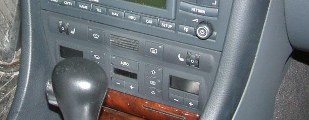
27 2a. Upgrading the climate control faceplate To match the color of the RNS-E (for pre-2002 C5 A6/S6/allroad cars only) Please note: This is optional cosmetic procedure that will not impact the function of your RNS-E. It is best to have your battery disconnected during this upgrade. Standard disclaimer: You do all these upgrades at your own risk to your car and your factory Audi warranty.


28 2b. RNS-E Installation Swapping climate control faceplate (Removing Symphony I head unit using radio removal tools) These tools can be purchased on or via The part number is T10057.
 related post: http://forums.audiworld.")
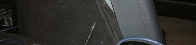
29 2c. RNS-E Removal of C5 Climate Control Unit Please note: Use a 8MM socket to remove these two screws. This can only be done when your Symphony head unit is completely removed. Also, please reference Henry Liu s (BostonDriver s) related post: Thanks to Henry Liu / BostonDriver for this picture
 Please note:")


30 2d. RNS-E Removal of C5 Climate Control Unit (rear clips only when a Symphony I / II is mounted above) Please note: Upon removing the climate control unit, I noticed that both bottom corners were held in by this metal tab. I was able to insert a small screw driver or plastic putty knife below the control unit to bend this metal tab down while removing the unit.
.")
31 2e. RNS-E Installation C5 A6/S6/RS6/allroad climate control faceplates (rear of climate control unit) Please note: Some units require either a Torx (T7) or a precision Phillips head. In either case, I would highly recommend using precision screwdriver (can be found at ). I found that the screws behind a climate control were T7 and were in very tight; the last thing you want to do is strip the torx heads.


32 2f. RNS-E Removal of C5 Climate Control Faceplate Front side Back side


33 2g. RNS-E Installation C5 A6/S6/RS6/allroad climate control faceplates (color differences for pre/post 2002 faceplates) Pre-2002 (gloss black) (matte black/grey) These two climate faceplates also have a different button. With a little extra work, you can swap the OFF button into a your faceplate (I decide not to attempt it and kept the A and arrow in place as it still functions as the off button for my unit. To do this, just push on the rear of the button so that it pops out from the front of the faceplate. Thanks to Lee Hicks for these details. Please note: These pictures do not do an accurate job of distinguishing the color differences between these two versions.
 Without heated")


34 2h. RNS-E Installation C5 A6/S6/RS6/allroad climate control faceplates (from /2005 model years) Without heated seats or cold-weather package With heated seats and cold-weather package Please note: The only downside to the upgraded cluster faceplate is that the black/grey material is prone to flaking and wear marks. Many C5 owners have noted this in some of the other interior plastics that share this same black/grey texture. Of course, your mileage may vary.


35 2i. RNS-E Installation C5 A6/S6/RS6/allroad climate control faceplate (RNS-E and climate control faceplate The Finished Product!!) Before After
36 3a. OEM RNS-E or Symphony II (with SAT button): Plug-and-Play cable to enable audio pass-through for: OEM SAT tuner (Sirius or XM) and: OEM Phatbox MP3 player or OEM trunk CD Changer or IceLink Ipod adaptor (trunk mounted version) or Blitzsafe audio interface (ideal for auxiliary audio input etc) Special Thanks to Lee Hicks ( lee@nsxjr.com ) for discovering all these details and sharing them with the rest of the Audi community. I would also like to thank Todd Snodgrass (todd1010) for building the first plug/play cable for his SAT tuner and Phatbox. Both Lee and Todd are model Audi enthusiasts. Thanks guys!! For further reference, please Lee s excellent documentation on how he installed/integrated the OEM XM SAT tuner and Symphony II head unit in his 2001 A6:
37 3b. Parts list Kenwood Cable (model#: CA-C2EX) source: T8s Connector (Audi part# 3D ; order just one) source: or Function: connection for CAN H/L and audio pass-through Pins/wires for T8s (Audi part# ; order quantity of 4) source: see above T8r Connector (Audi part# 3B ; order just one) source: or Function: connection for power and ground Pins/wires for T8r (Audi part# ; order just one) source: see above Blade-style fuse holder with 3AMP fuse source: any autoparts store (NAPA etc) Miscellaneous parts Black fabric tape and electrical tape AWG butt connectors Shrink tubing 4 different colors (for power, ground, CAN H and L) of 16 gauge stranded wire (15 feet long each) (can be sourced from local car stereo installation shop for a small fee) Bladed fuse holder and 5amp fuse Misc. butt connectors etc Assumption: OEM round 13-pin trunk CD changer cable is already installed in trunk; if not, additional wiring will need take place. Also, some of the parts above might not be needed if your Audi was prewired (2004+) for the SAT tuner. Please note: You can also attempt to create this cable when using the OEM glovebox CD changer (found in B6/B7 A4/S4 and new A3) but will require much more additional wiring between the OEM SAT tuner and where your OEM glovebox changer is located.
 1 5 4 2 You ll have to unhook the VAG Interface and two wires")


38 3c. OEM SAT Tuner Installation (Removing drivers side lower dash for access to power/ground sources) You ll have to unhook the VAG Interface and two wires from a lower dome light before the lower dash can be removed.very easy. 3 Using an 8MM socket wrench you ll need to unscrew the following screws to be able to remove the lower dash. I recommend following this order..and reinstalling in reverse order. Screw#1 is behind the fuse box panel. Screws #4/#5 are underneath the upper trim plate.


.")
39 3d. OEM SAT Tuner Installation An common source for power and ground to power OEM SAT tuner Ignition Power = 75X Constant Battery Power = 30 (the OEM SAT tuner can run off constant power; the CANbus will shut it on/off with the Audi head unit) Common area for ground follow the brown wires Please note: Before you unscrew these terminal connectors, make sure your metal socket wrench does not touch any metal parts of the lower dash area (you could damage other electronic components). I would highly recommend disconnecting the battery just prior to connecting to these power sources
 for future installation of: OEM SAT (XM")


40 3e. OEM SAT Tuner Installation Access to CANbus (High and Low) Option A (pre-2002 C5 A6): make sure you have access to CANbus to control the SAT tuner A second set of CAN H & L wires were spliced into this harness (and left under the lower dash area) for future installation of: OEM SAT (XM or Sirius) tuner and/or OEM BlueTooth cell phone kit and/or Dietz A/V interface or other devices that require an interface in to the CANbus network. CAN H & L wires will be routed to the 20 pin connector behind my RNS-E Routed to the instrument cluster for CAN H & L interface Please note: This is applicable to a pre-2002 C5 A6/allroad. Because you will be taping into the CANbus from behind the instrument cluster. It just makes sense to have an extra set of wires for CAN H/L inside the dash for future OEM upgrades etc that require a connection into the CANbus. Audi Part#:

41 3f. OEM SAT Tuner Installation Access to CANbus (High and Low) Option B (2002+ C5 A6): make sure you have access to CANbus to control the SAT tuner Connector I: Add a wire tap to these wires and run the wires to the drivers side lower dash area. Pin # 7 = CAN H, Pin # 12 = CAN L Please note: This is mostly applicable to a C5 A6/allroad/RS6/S6 that isn t already prewired from the factory for OEM SAT (The 2003 RS6, C5 A6/allroad would have the prewiring for OEM SAT). Courtesy of Ted Basile ( teddybgame@hotmail.com )
. 8 wires for audio input and control are plugged into this blue connector Audi Wiring harness: Audi Part#: 4B0-051-735B www.clairparts.")
42 3g. OEM SAT Tuner Installation OEM CD changer cable (This can support the audio interface from SAT tuner and other device) Ground wire can be connected to red 10 pin OR connected to main ground point in RNS-E plug/play harness (Hint: Look for the thick brown wire). 8 wires for audio input and control are plugged into this blue connector Audi Wiring harness: Audi Part#: 4B B Male side: plugs to: 1) OEM Phatbox cable 2) OEM CD trunk changer 3) Ipod IceLink (trunk version) 4) BlitsSafe trunk adaptor


43 3h. OEM SAT Tuner installation (Running wiring from trunk to dash area) For this exercise, I chose to use Streetwire brand Speedwire (source: autotoys.com) to run the necessary extra wire from the lower dash/fuse box area along the door sills to the trunk. My Speed wire has 9 different colors of 18 gauge wire. For this project I only used 4 of the 9 wires, however, I can use the other 5 wires for a future project (maybe installing the OEM Parktronic components who knows).

44 3i. OEM SAT Tuner installation removal of side trim (Running wiring from trunk to dash area) This process is fairly easy and only requires a flathead and phillips head screw driver and a 2 plastic putty knife to pop the trim out and run the wires to the trunk area.


45 3j. OEM SAT Tuner installation (Running wiring from trunk to dash area)
 Pins/wires (Audi")

46 3k. OEM SAT Tuner Installation (Power/Ground cable) Pins/wires (Audi part#: ) Power and ground wires with a 5amp fuse T8r connector (Audi part#: 3B )
 I labeled all of my wires 1-8")
 T8s connector (Audi part#")
47 3l. OEM SAT Tuner Installation (Plug/Play OEM SAT Tuner cable) I labeled all of my wires 1-8 to simplify the process Pins/wires: (Audi part# ) T8s connector (Audi part# 3D )
 #5: Audio Ground (brown) #6: Left Channel Audio (red) #7: Right Channel Audio (purple) Kenwood CA-C2EX Cable Male side (90 Angle)- plugs into: 1) Phatbox cable 2) OEM CD changer")
 #3: Left Channel Audio (red) #4: Right Channel Audio (purple) #8: Audio Ground (brown) Note: wire size is 22-24awg (tiny).")
48 3m. OEM SAT Tuner Installation Plug/Play audio interface (opening up Kenwood cable and splicing wires) Special connector plug for OEM Phatbox (included with purchase of Audi Phatbox) Connector T8s: (kenwood wires) #5: Audio Ground (brown) #6: Left Channel Audio (red) #7: Right Channel Audio (purple) Kenwood CA-C2EX Cable Male side (90 Angle)- plugs into: 1) Phatbox cable 2) OEM CD changer (trunk) 3) Dension Ipod IceLink (trunk) 4) Blitzsafe adaptor (trunk) Green wire is cut and taped off I recommend using a sharp x-acto knife to pierce the rubber tubing to expose the colored wires. Connector T8s: (kenwood wires) #3: Left Channel Audio (red) #4: Right Channel Audio (purple) #8: Audio Ground (brown) Note: wire size is 22-24awg (tiny). I also used heat shrink tubing over these connections (highly recommended). Female side plugs into Existing CDC cable in trunk from RNS-E, Symphony II or Concert headunits (with SAT capability)


49 3n. OEM SAT Tuner Installation Plug/Play audio interface (taping up the finished cable) Finished Product!! Time to cover everything up with fabric tape and/or heat shrink tubing Connector T8s: #1: CAN L #2: CAN H
50 3o. OEM SAT Tuner Installation Connections at tuner (Both XM and Sirius will look the same) Connector T8s: (audio in/out and CANbus) Connector T8r: (power/ground) Male FAKRA connectors Brown Green (Terrestrial) (Satellite) Part# s for SAT Tuner modules: Sirius: 8E D / 8E D (either part# will work) XM: 8E E / 8E E See also (go to quicklinks) for more details. Please note: The SAT tuner modules for C6 A6, D3 A8 and Q7 have slightly different connectors due to the MOST architecture.


51 3p. OEM SAT Tuner Installation Plug/Play audio interface (Adding OEM Phatbox) Male 13 Pin DIN connector Blue/Green/Yellow 20 pin connector If you have a 2003/2004/2005 A6/allroad/S6/RS6, then you ll need the CD Changer cable to connect your PhatBox to the RNS-E plug/play cable Audi Wiring harness: Audi Part#: 4B B Courtesy of Ted Basile ( teddybgame@hotmail.com )
 Can be used to plug in another audio source (with your OEM")

52 3q. OEM SAT Tuner Installation Plug/Play audio interface (Other Audio input devices to plug in at the trunk via the plug/play interface) Blitzsafe Part#: AUDI/AUX DMX V.1 For connection to your Apple Ipod Female round 13 pin DIN connector (connects to custom plug/play audio interface) Can be used to plug in another audio source (with your OEM SAT tuner) Dension IceLink for Apple Ipod Please note: These are some examples of other audio inputs to your Symphony II or RNS-E via the SAT audio pass-through. Any other devices that do not plug into the trunk mounted CD changer cable will require additional wiring and are not outlined in these pictures. Courtesy of Ted Basile ( teddybgame@hotmail.com )
 Brown Parts List: - Brown FAKRA connector for using aftermarket Sirius or XM antenna (Source: part# FA1-NFSJ-C01-0 Source: www.digikey.com ) - Sirius dual input splitter (source: www.")
53 3r. OEM SAT Tuner Aftermarket Sirius Antenna (Dual lead splitter and single lead aftermarket micro antenna pictured) White Curry Brown FAKRA replaces Curry (see further documentation on ) Brown Parts List: - Brown FAKRA connector for using aftermarket Sirius or XM antenna (Source: part# FA1-NFSJ-C01-0 Source: ) - Sirius dual input splitter (source: - Sirius micro single lead antenna (part# SIR-1SAF)


54 3s. OEM SAT Tuner (Sirius) Connecting everything all together Brown and white FAKRA connectors plug in here Plug/Play cable gets tucked behind the bracket A6/S6/RS6 Avant / allroad CD Changer bracket: Audi Part#: 4B E Please note: My CD changer bracket was previously modified to fit the Phatbox in the lower section. The Sirius tuner will be mounted on top of the Phatbox with a custom mounting bracket. Your mounting location will be slightly different but will probably be located in this part of your trunk.

 to see what works best in your geographic area.")
.")
55 3t. Temporary location of aftermarket SAT antenna (applicable to C5 A6/S6 Avant & allroad) Micro antenna doesn t work well here. Micro antenna works much better here. Please note: The location of your aftermarket Sirius or XM antenna should be the last thing you do. You should test various areas in your car (rear roof, rear deck, front dash etc) to see what works best in your geographic area. Some of the single lead micro antennas do not perform as well as the larger/older dual-lead antennas. You should also keep in mind, that metallic tinting will impact your antenna s performance (if the antenna is mounted inside your car). You can search or for more information and ideas. Special thanks to Lee Hicks for this information / Ted Basile ( teddybgame@hotmail.com )


 Stay tuned for more install pix,")
56 3u. Adding OEM submarine style (applicable to C5 A6/S6 Avant & allroad and those with any OEM roof-mounted antenna) FAKRA connectors: Blue = GPS Red/Pink = GSM/Cellphone/OnStar Telematics etc White = SAT Tuner (Satellite signal) Black = SAT Tuner (Terrestrial signal) Stay tuned for more install pix, part# s and details.
SIR-GM1 GM CLASS-2 BUS COMPATIBLE SIRIUS SATELLITE RADIO TUNER
 SIR-GM1 GM CLASS-2 BUS COMPATIBLE SIRIUS SATELLITE RADIO TUNER Installation Guide Congratulations on your purchase of the SIR-GM1 the GM Compatible SIRIUS Satellite Radio Tuner! Your SIR-GM1 is designed
GENUINE PARTS ! CAUTION
 GENUINE PARTS SATELLITE RADIO INSTALLATION INSTRUCTIONS 1. DESCRIPTION: SATELLITE RADIO SYSTEM 2. PART NUMBERS: XM tuner kit 999U9-NV003 Sirius tuner kit 999U9-NV004 XM antenna kit 999U9-VQ006 Sirius antenna
GENUINE PARTS CAUTION
 GENUINE PARTS SATELLITE RADIO INSTALLATION INSTRUCTIONS 1. DESCRIPTION: SATELLITE RADIO SYSTEM 2. PART NUMBERS: XM tuner kit 999U9-NV003 XM antenna kit 999U9-VR000 Sirius tuner kit 999U9-NV004 Sirius antenna
ELECTRONICS CORP. VOD1021/VOD1022 Drop Down Video TV/Monitor with DVD. Installation Guide
 ELECTRONICS CORP. VOD1021/VOD1022 Drop Down Video TV/Monitor with DVD Installation Guide Important Notice An LCD panel and/or video monitor may be installed in a motor vehicle and visible to the driver
Installation instructions, accessories. Subwoofer. Volvo Car Corporation Gothenburg, Sweden. Page 1 / 29
 Installation instructions, accessories Instruction No 30752136 Version 1.1 Part. No. 30752135 Subwoofer Volvo Car Corporation Subwoofer- 30752136 - V1.1 Page 1 / 29 Equipment A0000162 A0000161 A0801178
ELECTRONICS CORP. VOD715 Drop Down Video Monitor with DVD FM SELECT PAUSE L R. Installation Guide
 IR VIDEO INPUT AUDIO L R ELECTRONICS CORP. VOD715 Drop Down Video Monitor with DVD PAUSE REV FWD SOURCE ON OFF AUTO VOLUME FM SELECT S HEADPHONES Installation Guide Important Notice It is unlawful in most
1- Disconnect your Car battery by disconnecting the negative ground terminal from the battery, to prevent shock, or damage to you car.
 DIY: How to install MFD into Passat with Double-Din (DD) Radio -------------------------------------------------------------------------------- NOTE: This installation is for all Passats (Sedan or Avant)
GENUINE PARTS. SIRIUS Under Glass Antenna Kit
 GENUINE PARTS SATELLITE RADIO INSTALLATION INSTRUCTIONS 1. DESCRIPTION: Satellite Radio System 2. APPLICATION: Pathfinder (2006-2007) 3. PART NUMBERS: XM Tuner Kit 999U9-AS005 SIRIUS Tuner Kit 999U9-AS006
DVB-E65-TV. Compatible with BMW E65 Professional navigation systems with 8.8 monitor
 dvblogic DVB-T Tuner Compatible with BMW E65 Professional navigation systems with 8.8 monitor Vehicles with factory TV-tuner port (Factory TV-tuner must be uninstalled) Product features Full plug and play
Warning and Safety Information. FCC Information
 Installation Manual Warning and Safety Information FCC Information This device complies with FCC Rules Part 15 Operation and is subject to the following two conditions: (1) This device may not cause harmful
INSTALLATION MANUAL. Full Plug n Play kit for installing Sirius Radio in compatible vehicles
 ARC-MFSAT357 ARC-MFSAT357 INSTALLATION MANUAL Full Plug n Play kit for installing Sirius Radio in compatible vehicles Required for Install: 1. Satellite Ready MyFord Vehicle 2. ARC-MFSAT357 Installation
Audi A6 MMI Apple TV (or any AV input) Guide 3G MMI (some details noted for 2G MMI) all for less than $250
 Guide 3G MMI (some details noted for 2G MMI) all for less than $250") Audi A6 MMI Apple TV (or any AV input) Guide 3G MMI (some details noted for 2G MMI) all for less than $250 Necessary Products *(Different product needed for 2G) **(Substitute similar product if you want)
Audi A6 MMI Apple TV (or any AV input) Guide 3G MMI (some details noted for 2G MMI) all for less than $250 Necessary Products *(Different product needed for 2G) **(Substitute similar product if you want)
imac Intel 20" EMC 2133 and 2210 LCD Backlights (CCFL) Replacement
 Replacement") imac Intel 20" EMC 2133 and 2210 LCD Backlights (CCFL) Replacement The CCFL back lights are replaceable. I have pulled mine apart and documented my method. '''NOTE''' This is not for the feint hearted!
imac Intel 20" EMC 2133 and 2210 LCD Backlights (CCFL) Replacement The CCFL back lights are replaceable. I have pulled mine apart and documented my method. '''NOTE''' This is not for the feint hearted!
Gazer VI700A-SYNC2 and VI700W- SYNC2 INSTALLATION MANUAL
 Gazer VI700A-SYNC2 and VI700W- SYNC2 INSTALLATION MANUAL Contents List of compatible cars... 3 Package contents... 4 Special information... 6 Car interior disassembly and connection guide for Ford Focus...
GENUINE PARTS SATELLITE RADIO INSTALLATION INSTRUCTIONS. 1. DESCRIPTION: Satellite Radio System 2. APPLICATION: Frontier (2006~)
") GENUINE PARTS SATELLITE RADIO INSTALLATION INSTRUCTIONS 1. DESCRIPTION: Satellite Radio System 2. APPLICATION: Frontier (2006~) Xterra (2006~) 3. PART NUMBERS: XM Tuner Kit 999U9-AS003 SIRIUS Tuner Kit
GENUINE PARTS SATELLITE RADIO INSTALLATION INSTRUCTIONS 1. DESCRIPTION: Satellite Radio System 2. APPLICATION: Frontier (2006~) Xterra (2006~) 3. PART NUMBERS: XM Tuner Kit 999U9-AS003 SIRIUS Tuner Kit
PowerBook G4 Aluminum 12" GHz LCD panel upgrade
 PowerBook G4 Aluminum 12" 1-1.5 GHz LCD panel upgrade Upgrade a 1400x1050 LCD panel. Written By: martin ifixit CC BY-NC-SA www.ifixit.com Page 1 of 18 INTRODUCTION The original LCD 1024x768 resolution
SCC1C SiriusConnect TM Vehicle Tuner. Installation Guide
 SCC1C SiriusConnect TM Vehicle Tuner Installation Guide Congratulations on the Purchase of your new SIRIUS SCC1C SiriusConnect Vehicle Tuner. The SCC1C SiriusConnect Vehicle Tuner is designed to work with
ARC-MFSAT INSTALLATION MANUAL
 ARC-MFSAT ARC-MFSAT INSTALLATION MANUAL Full Plug n Play kit for installing Sirius Radio in compatible vehicles Required for Install: 1. Satellite Ready MyFord Vehicle 2. ARC-MFSAT Installation Kit 3.
SCdefault. 900 Installation instructions. Accessories Part No. Group Date Instruction Part No. Replaces :36-29 Sep
 SCdefault 900 Installation instructions SITdefault Upgrade to Premium 300 sound system MONTERINGSANVISNING INSTALLATION INSTRUCTIONS MONTAGEANLEITUNG INSTRUCTIONS DE MONTAGE Accessories Part No. Group
DVB-LR10. Compatible with Land Rover touch-screen navigation systems version 2
 dvblogic DVB-T Tuner Compatible with Land Rover touch-screen navigation systems version 2 Product features full plug and play vehicle-specific dual DVB-T Tuner with two active DVB-T glass-mount antennas
DT1-NTG2. Compatible with Mercedes Benz Comand APS NTG2 navigation systems
 dvblogic DVB-T Tuner Compatible with Mercedes Benz Comand APS NTG2 navigation systems Product features Full plug and play vehicle-specific dual DVB-T Tuner + USB-AV-Player DVB-T-Tuner MPEG4 compatible
Gazer VI700A-SYNC/IN and VI700W- SYNC/IN INSTALLATION MANUAL
 Gazer VI700A-SYNC/IN and VI700W- SYNC/IN INSTALLATION MANUAL Contents List of compatible cars... 3 Package contents... 4 Special information... 6 Car interior disassembly and connection guide for Ford
Head Unit-to-Fibre Optic interface (OPTI-1) and Steering Wheel Control Installation
 and Steering Wheel Control Installation") Head Unit-to-Fibre Optic interface (OPTI-1) and Steering Wheel Control Installation Important notes related to the OPTI-1 Interface Unit: 1- Not supporting the 4 channel right now. In an SL it won't matter;
Head Unit-to-Fibre Optic interface (OPTI-1) and Steering Wheel Control Installation Important notes related to the OPTI-1 Interface Unit: 1- Not supporting the 4 channel right now. In an SL it won't matter;
DVB-C25. Compatible with navigation systems Mercedes Benz Comand 2.5
 dvblogic DVB-T Tuner Compatible with navigation systems Mercedes Benz Comand 2.5 Product features full plug and play vehicle-specific dual DVB-T Tuner with two active DVB-T glass-mount antennas integrated
DT1-LR10. Compatible with Land Rover touch-screen navigation systems version 2
 dvblogic DVB-T Tuner Compatible with Land Rover touch-screen navigation systems version 2 Product features Full plug and play vehicle-specific dual DVB-T Tuner + USB-AV-Player DVB-T-Tuner MPEG4 compatible
DT1-PCM21. for Porsche PCM2.1 navigation systems
 Product features dvblogic DVB-T Tuner for Porsche PCM2.1 navigation systems Full plug and play vehicle-specific dual DVB-T Tuner + USB-AV-Player DVB-T-Tuner MPEG4 compatible (HD) USB-AV-Player for USB-media
DT2-NTG45. for Mercedes Benz vehicles with Comand APS NTG4-212 and Comand Online NTG4.5 navigation systems
 dvblogic DVB-T Tuner for Mercedes Benz vehicles with Comand APS NTG4-212 and Comand Online NTG4.5 navigation systems Product features Full plug and play vehicle-specific dual DVB-T Tuner + USB-AV-Player
SC-C1M SiriusConnect TM Vehicle Tuner
 SC-C1M SiriusConnect TM Vehicle Tuner For Special Market Applications Installation Guide Congratulations on the Purchase of your new SIRIUS SC-C1 SiriusConnect TM Vehicle Tuner. The SC-C1M is packaged
DVB-C20. Compatible with navigation systems Mercedes Benz Comand 2.0 Comand APS CD Comand APS 220
 dvblogic DVB-T Tuner Compatible with navigation systems Mercedes Benz Comand 2.0 Comand APS CD Comand APS 220 Product features full plug and play vehicle-specific dual DVB-T Tuner with two active DVB-T
DT1-LR. for Landrover touch-screen navigation systems version 1
 dvblogic DVB-T Tuner for Landrover touch-screen navigation systems version 1 Product features Full plug and play vehicle-specific dual DVB-T Tuner + USB-AV-Player DVB-T-Tuner MPEG4 compatible (HD) USB-AV-Player
3M Distribution Box (DDB)
") 3M Distribution Box (DDB) Merged Copper and Fiber Pole/Post Mount Enclosure Installation Instructions November 2015 78-0015-2736-1-A 2 November 2015 78-0015-2736-1-A Contents 1.0 General 2.0 Enclosure
3M Distribution Box (DDB) Merged Copper and Fiber Pole/Post Mount Enclosure Installation Instructions November 2015 78-0015-2736-1-A 2 November 2015 78-0015-2736-1-A Contents 1.0 General 2.0 Enclosure
Cellular Signal Booster
 Drive 4G-X Cellular Signal Booster THE ALUMINUM CASING OF YOUR SIGNAL BOOSTER!! WILL ADJUST TO THE TEMPERATURE OF ITS ENVIRONMENT, BUT IS DESIGNED TO PROTECT THE SIGNAL BOOSTER TECHNOLOGY. FOR EXAMPLE,
INSTALLATION INSTRUCTIONS FOR
 INSTALLATION INSTRUCTIONS FOR MODEL 2240LED www.sportablescoreboards.com 1 Table of Contents 8 X 7 INDOOR SCOREBOARD... 3 THE SCOREBOARD SYSTEM SHOULD INCLUDE THE FOLLOWING PARTS:... 3 INSTRUCTIONS FOR
24-Fiber LANLINXS (Model # ) 48-Fiber LANLINXS (Model # ) User Manual
 48-Fiber LANLINXS (Model # ) User Manual") 24-Fiber LANLINXS (Model # 055-8632-5000) 48-Fiber LANLINXS (Model # 055-8832-5000) User Manual 24-Fiber LANLINXS (Model # 055-8632-5000) 48-Fiber LANLINXS (Model # 055-8832-5000) User Manual, Part Number
24-Fiber LANLINXS (Model # 055-8632-5000) 48-Fiber LANLINXS (Model # 055-8832-5000) User Manual 24-Fiber LANLINXS (Model # 055-8632-5000) 48-Fiber LANLINXS (Model # 055-8832-5000) User Manual, Part Number
Converting BMW E39 Japanese Nav system to Euro Nav System Making the nav work in NZ (or Australia/Malaysia/UK etc)
") Converting BMW E39 Japanese Nav system to Euro Nav System Making the nav work in NZ (or Australia/Malaysia/UK etc) NOTE: These instructions work equally well for the E38 7-series, as the vehicle is electrically
Converting BMW E39 Japanese Nav system to Euro Nav System Making the nav work in NZ (or Australia/Malaysia/UK etc) NOTE: These instructions work equally well for the E38 7-series, as the vehicle is electrically
Satellite Radio. Expand Your Factory Radio ISSR bit & 29-bit LAN. Owner s Manual Gateway. add. Harness Connection USB. Port 1 Port.
 Expand Your Factory Radio Harness Connection add Satellite Radio Dip Switches Port 1 Port 2 (See Manual) USB GM 11-bit & 29-bit LAN Owner s Manual Gateway ISSR12 Table of Contents 1. Introduction 2. Precautions
DT2-LR12. Compatible with Land Rover vehicles with touch-screen navigation systems version 3
 dvblogic DVB-T Tuner Compatible with Land Rover vehicles with touch-screen navigation systems version 3 Product features Full plug and play vehicle-specific dual DVB-T Tuner + USB-AV-Player DVB-T-Tuner
AUDIO ROOF KIT P/N , , APPLICATION BEFORE YOU BEGIN KIT CONTENTS. Instr Rev Page 1 of 6
 AUDIO ROOF KIT P/N 2882064, 2882065, 2882066 APPLICATION Verify accessory fitment at Polaris.com. BEFORE YOU BEGIN Read these instructions and check to be sure all parts and tools are accounted for. Please
Expand Your Factory Radio add Satellite Radio Harness Connection
 Expand Your Factory Radio Harness Connection add Satellite Radio Dip Switches Port 1 Port 2 (See Manual) USB Honda/Acura Owner s Manual GateWay Owner s Manual Media ISSR12 GateWay PXAMG 01-22-13 Table
Parts and Accessories Installation Instructions
 Parts and Accessories Installation Instructions Retrofit kit BMW Traffic Pro BMW Z4 (E 85) Retrofit kit part number: 65 90 0 301 533 65 90 0 153 186 Installation time: The installation time of approx.
NNG-GM2 Navigation interface for GM vehicles equipped with LVDS MYLink/CUE NTV-KIT552
 3950 NW 120 th Ave, Coral Springs, FL 33065 TEL 561-955-9770 FAX 561-955-9760 NNG-GM2 Navigation interface for GM vehicles equipped with LVDS MYLink/CUE NTV-KIT552 This installation manual is for NNG-GM2
Cable ISOBUS Active Termination
 ISOBUS Retrofit Kit Ag Leader Technology Note: Indented items indicate parts included in an assembly listed above Part Name/Description Part Number Quantity ISOBUS Retrofit Kit 4100843 1 Hex Head Bolt
LCM1331FD / LCM1331FDW Owner s/installation Manual 13.3 Flip-Down In Vehicle Entertainment System
 LCM1331FD / LCM1331FDW Owner s/installation Manual 13.3 Flip-Down In Vehicle Entertainment System Audiovox Specialized Applications, LLC 23319 Cooper Dr. Elkhart, IN 46514 219-264-3135 www.asaelectronics.com
In-Wall Control Mount for ipod Touch
 In-Wall Control Mount for ipod Touch INTRODUCTION The Mirage KP-iOS is an in-wall system that allows ipod touch (4th generation) to become a semi-permanent fixture in your wall. The system allows you to
Assembling and Mounting the Presentation Display, Speakers, Speaker Screens, and Table Door
 CHAPTER 8 Assembling and Mounting the Presentation Display, Speakers, Speaker Screens, and Table Door July 13, 2012, This document provides you with the procedures you perform to assemble and mount the
DVB-PCM30. for Porsche PCM3.0 and 3.1 navigation systems
 dvblogic DVB-T Tuner for Porsche PCM3.0 and 3.1 navigation systems Product features full plug and play vehicle-specific dual DVB-T Tuner with two active DVB-T glass-mount antennas integrated into and controllable
Lynx Broadband Installation Manual for Residential Packages with a 35 db Amp Quick Start Guide (first 3 pages)
") Lynx Broadband Installation Manual for Residential Packages with a 35 db Amp Quick Start Guide (first 3 pages) 1. Be sure that your kit includes all the parts shown in the Check the Equipment section in
Lynx Broadband Installation Manual for Residential Packages with a 35 db Amp Quick Start Guide (first 3 pages) 1. Be sure that your kit includes all the parts shown in the Check the Equipment section in
Congratulations on your purchase of the SIR-ECL1 the ECLIPSE Compatible SIRIUS Satellite Radio Tuner!
 Installation Guide Congratulations on your purchase of the SIR-ECL1 the ECLIPSE Compatible SIRIUS Satellite Radio Tuner! Your new SIRIUS Tuner is designed to work with 2005 and up ECLIPSE E-LAN headunits
Welcome to your. Wireless transmitter and receiver kit
 Welcome to your Wireless transmitter and receiver kit Your Handykam camera Transmitter/Receiver (T/R) kit is designed to transmit and receive both pictures and sound (video and audio) with a choice of
RSL MusicPower Plug-In Installation Manual For Naim NAC 72 Preamp
 RSL MusicPower Plug-In Installation Manual For Naim NAC 72 Preamp (Updated to reflect the adjustable gain output boards Z200V) www.ryansoundlab.com RSL MusicPower Plug-In Installation Manual for Naim NAC
Home Monitoring. Wired Color Camera. User Manual. For indoor/outdoor use. Do not use in wet locations.
 45231 Home Monitoring Wired Color Camera User Manual For indoor/outdoor use. Do not use in wet locations. www.jascoproducts.com 1-800-654-8483 2 Thank you for purchasing the GE 45231 Wired Color Camera.
IP-LINX Fiber :: X-XXXX
 Fiber :: 055-797X-XXXX User Manual Telect, Inc. All rights reserved. 146653-A0 Table of Contents Chapter 1: Introduction...3 1.1 Tools Required...3 1.2 Additional Parts...3 1.3 Assemblies...3 Chapter 2:
AT-AUTO (tm) QRO Keyline Upgrade Kit Installation Manual
 QRO Keyline Upgrade Kit Installation Manual") AT-AUTO (tm) QRO Keyline Upgrade Kit Installation Manual P.O. Box 341543 Beavercreek, Ohio 45434 5 September, 2015 Copyright 2015 ii Contents 1 Introduction 2 1.1 General Description and Purpose........................
AT-AUTO (tm) QRO Keyline Upgrade Kit Installation Manual P.O. Box 341543 Beavercreek, Ohio 45434 5 September, 2015 Copyright 2015 ii Contents 1 Introduction 2 1.1 General Description and Purpose........................
ASSEMBLY, INSTALLATION, AND REMOVAL OF CONTACTS AND MODULES
 ASSEMBLY, INSTALLATION, AND REMOVAL OF CONTACTS AND MODULES FOR 75 OHM AND 75 OHM HD COAXIAL CONTACTS AND MODULES Table of Contents SECTION 1 RECEIVER CONTACT ASSEMBLY INSTRUCTIONS SECTION 2 ITA CONTACT
EAGLE RE-1 CONTROLLER
 EAGLE RE-1 CONTROLLER For Use On ALL MotoSAT Mounts Supported Systems HD SL5 DirecTV HD DP3 Dish Network HD SC2 SHAW HD DP3 BELL TV EXECUTIVE 18" DirecTV 101 Dish Network 119 MSC-60 SHAW MD-500 Dish Network
Digital Audio Broadcast (DAB+ radio) retro fit to Discovery 4 By Peter A.
 retro fit to Discovery 4 By Peter A.") 1 Digital Audio Broadcast (DAB+ radio) retro fit to Discovery 4 By Peter A. A great thing about this site are the friendly and knowledgeable people you meet. One day just looking around I stumbled on a
1 Digital Audio Broadcast (DAB+ radio) retro fit to Discovery 4 By Peter A. A great thing about this site are the friendly and knowledgeable people you meet. One day just looking around I stumbled on a
Video SystemVideo System
 PublishedPublished: May 4, 2005 Video SystemVideo System Video System Component Location ItemItem Part NumberPart Number 1 - Television tuner module 2 - Rear seat entertainment control module 3 - DVD (digital
CI-VL2-PSA-HSD. for Citroen and Peugeot vehicles with SMEG or SMEG+ navigation with 4pin HSD LVDS connector on the monitor
 v.link Video-inserter for Citroen and Peugeot vehicles with SMEG or SMEG+ navigation with 4pin HSD LVDS connector on the monitor Video-inserter with 2 video + RGB + rear-view camera input and CAN control
FOSC 450 C6 and D6 Closures
 FOSC 450 C6 and D6 Closures I N S T A L L A T I O N I N S T R U C T I O N Fiber Optic Splice Closure 1. General Product Information The FOSC 450 C6 and D6 fiber optic splice closures use compressed gel
How To: Replace the stock Antenna with a CB Antenna A CFans Members Mod Project by coyote
 How To: Replace the stock Antenna with a CB Antenna A CFans Members Mod Project by coyote Skill Level: Easy Disclaimer: Please use caution and seek professional assistance when necessary. ColoradoFans.com,
iphone 7 Plus LCD Screen and Digitizer Replacement
 iphone 7 Plus LCD Screen and Digitizer Replacement Replace just the bare front panel not including the home/touch ID sensor, front-facing camera and sensor cable, or earpiece speaker in an iphone 7 Plus.
imiv Installation Manual
 imiv Installation Manual Version: 1.0 1 P a g e Table of Contents 1 Installation Options... 3 1.1 Front Installation... 3 1.1.1 Checklist... 3 1.1.2 Connection Diagram and Installation Instructions...
Satellite Radio. Owner s Manual. Expand Your Factory Radio. Honda/Acura PXAMG. GateWay. add
 Expand Your Factory Radio Harness Connection add Satellite Radio Dip Switches Port 1 Port 2 (See Manual) USB Honda/Acura Owner s Manual GateWay Owner s Manual Media ISSR12 GateWay PXAMG isimple A Division
Replacing the PanelMate epro PS, PanelMate epro PS EE, and PanelMate epro PS OD 7685x-12 Series Backlight Assembly
 Replacing the PanelMate epro PS, PanelMate epro PS EE, and PanelMate epro PS OD 7685x-12 Series Backlight Assembly Introduction The Backlight Replacement Kit provides a replacement backlight for the PanelMate
7 LCD Color Monitor 8 LCD Color Monitor OWNER S MANUAL
 7 LCD Color Monitor 8 LCD Color Monitor OWNER S MANUAL INTRODUCTION OHM720, OHM820 The Clarion OHM720/OHM820 is a full-featured 7 /8 LCD Color Monitor that can be used as a stand-alone monitor, or can
JACK Digital HDTV Over-the-Air Antenna
 JACK Digital HDTV Over-the-Air Antenna w/built-in SureLock Digital TV Signal Meter TM OA8200-White OA8201-Black SPECIFICATIONS Dimensions: 11.25 H x 16 W x 12.5 L Powered Amplifier +12 volt / 100 ma working
IPad 4 REPAIR GUIDE. Version Edition
 IPad 4 REPAIR GUIDE Version 1 2016 Edition IPad 4 REPAIR GUIDE LCD AND DIGITIZER REPLACEMENT RiAna Soto Repair Training Specialist rsoto@cellairis.com FOR EVERY REPAIR MAKE SURE TO COMPLETE, INITIAL, AND
UAV Ultimate Atari Video A7800
 UAV Ultimate Atari Video A7800 Basic Install guide because this is really easy mod to do! The UAV is a wonderful piece of tech for what it can do. To summarize, the UAV is a replacement video encoder and
IP-LINX. Installation Guide
 Installation Guide Installation Guide, 146653-4 Copyright 2017, Telect, Inc. All Rights Reserved Telect and Connecting the Future are registered trademarks of Telect, Inc. 22425 East Appleway Ave. # 11
Fully ly Automaticti. Motorised Satellite t TV System. User s manual REV
 REV. 1.0 Fully ly Automaticti Motorised Satellite t TV System User s manual Customer Help Line: 1300 139 255 Support Email: support@satkingpromax.com.au Website: www.satkingpromax.com.au www.satkingpromax.com.au
INSTALLATION INSTRUCTIONS FOR. MODEL 2230LED
 INSTALLATION INSTRUCTIONS FOR MODEL 2230LED www.sportablescoreboards.com 1 Table of Contents MODEL 2230LED... 3 8 X 4 INDOOR SCOREBOARD... 3 THE SCOREBOARD SYSTEM SHOULD INCLUDE THE FOLLOWING PARTS:...
IPad 3 (glass) REPAIR GUIDE. Version Edition
 REPAIR GUIDE. Version Edition") IPad 3 (glass) REPAIR GUIDE Version 1 2016 Edition IPad 4 REPAIR GUIDE LCD AND DIGITIZER REPLACEMENT RiAna Soto Repair Training Specialist rsoto@cellairis.com FOR EVERY REPAIR MAKE SURE TO COMPLETE, INITIAL,
IPad 3 (glass) REPAIR GUIDE Version 1 2016 Edition IPad 4 REPAIR GUIDE LCD AND DIGITIZER REPLACEMENT RiAna Soto Repair Training Specialist rsoto@cellairis.com FOR EVERY REPAIR MAKE SURE TO COMPLETE, INITIAL,
SATELLITE TV OPERATION / TECHNICAL MANUAL. Eagle II Controller
 SATELLITE TV OPERATION / TECHNICAL MANUAL Eagle II Controller 10 May 2018 2 Index Warnings... 4 Mount Definitions... 5 Controller Views... 6 Configuration and Software Versions... 8 Menus and Operations...
Original BMW Accessories. Installation Instructions.
 Original MW ccessories. Installation Instructions. ipod Interface Retrofit MW 5 Series (E 60, E 6) MW 6 Series (E 63, E 64) These installation instructions are only valid for cars with S 67 (CD changer)
OWNER'S MANUAL SIGNAL COMMANDER
 OWNER'S MANUAL SIGNAL COMMANDER THIS MANUAL CONTAINS INSTRUCTIONS FOR: LPDA 200 - INSTALLATION - OPERATION - TROUBLESHOOTING - EXPLODED PARTS DRAWING - WARRANTY AntennaTek, Inc. 425 S. Bowen, #4 Longmont,
Safety Information. Camera System. If you back up while looking only at the monitor, you may cause damage or injury. Always back up slowly.
 Table of Contents Introduction...3 Safety Information...4-6 Before Beginning Installation...7 Installation Guide...8 Wiring Camera & Monitor...9-10 Replacement Installation Diagram...11 Clip-On Installation
FOSC-600 C and D I N S T A L L A T I O N I N S T R U C T I O N
 FOSC-600 C and D I N S T A L L A T I O N I N S T R U C T I O N In-line and butt version Cold applied re-usable fiber optic closure Contents 1 Introduction 1.1 Product description 1.2 Capacity 2 General
ART2000i Digital Dimming System. Installation guide. Stock number *8200-
 ART2000i Digital Dimming System Installation guide Stock number 8200-0159 *8200- 0159* Useful Avolites phone numbers:- Avolites England Sales and service* (+44) (0) 20 8965 8522 Service out of hours* (+44)
VL2-PC-HSD. Compatible with Citroen and Peugeot vehicles with SMEG or SMEG+ navigation with 4pin HSD LVDS connector on the monitor
 v.link Video-inserter VL2-PC-HSD Compatible with Citroen and Peugeot vehicles with SMEG or SMEG+ navigation with 4pin HSD LVDS connector on the monitor Video-inserter with 2 video and 1 rear-view camera
Satellite Dish Installation Manual (Ver. 2) 1
 1") Satellite Dish Installation Manual Provided by DiscoverNet, Inc. Satellite Dish Installation Manual (Ver. 2) 1 Table of Contents Section 1: Introduction Page 3 Section 2: Recommended Tools and Materials
Satellite Dish Installation Manual Provided by DiscoverNet, Inc. Satellite Dish Installation Manual (Ver. 2) 1 Table of Contents Section 1: Introduction Page 3 Section 2: Recommended Tools and Materials
Integre4. Audiophile integrated amplifier. v1.2
 Owner s Manual Integre4 Audiophile integrated amplifier www.lab12.gr v1.2 Table of Contents It is yours Features Unpacking and Warnings Installation & Placement Front Panel Rear Panel Connections Remote
HR7012M / HR7012S. Custom Vehicle Headrests with 7 Slim Style LED LCD Satellite Monitors or Built-in DVD Player for Rear Entertainment HR7012M
 S S P HR7012M / HR7012S Custom Vehicle Headrests with 7 Slim Style LED LCD Satellite Monitors or Built-in DVD Player for Rear Entertainment HR7012M HR7012S Installation Guide 128-9047 IMPORTANT NOTICE
Caution. Hanging the Screen:
 Installation Instructions for Laminar and Laminar XL Projection Screens Caution 1. Read Instructions through completely before proceeding; keep them for future reference. Follow these instructions carefully.
Site Installation Model MP-8424
 Site Installation Model MP- Rev. //0 SCOREBOARD SITE INSTALLATION INSTRUCTIONS CAUTION: All American Scoreboards (AAS) recommends the sign be installed by a licensed contractor, and must meet all local
ISIS intouch NET Wi Fi Touch Screen Controller Owner s Manual and Instruction Guide
 ISIS intouch NET Wi Fi Touch Screen Controller Owner s Manual and Instruction Guide Table of Contents Overview... 2 Warnings... 3 Kit Includes... 4 Installation Steps... 5 Locate the intouch NET module
TracVision R6DX Installation Guide
 TracVision R6DX Installation Guide These instructions explain how to install the TracVision R6DX satellite TV antenna system on an RV or motor coach. Complete instructions on how to use the system are
Cellular Signal Booster
 Connect 4G-X Cellular Signal Booster !! IT IS VERY MPORTANT TO POWER YOUR SIGNAL BOOSTER US NG A SURGE PROTECTED AC POWER STRIP WITH AT LEAST A 1000 JOULE RATING. FAILURE TO DO THIS WILL VOID YOUR WARRANTY
Cellular Signal Booster
 Drive G-M Cellular Signal Booster THE ALUMINUM CASING OF YOUR SIGNAL BOOSTER!! WILL ADJUST TO THE TEMPERATURE OF ITS ENVIRONMENT, BUT IS DESIGNED TO PROTECT THE SIGNAL BOOSTER TECHNOLOGY. FOR EXAMPLE,
Mitsubishi WD57734 DLP Chip Replacement
 Mitsubishi WD57734 DLP Chip Replacement Replace the DLP chip in your Mitsubishi WD57734. Written By: David Sylvester ifixit CC BY-NC-SA www.ifixit.com Page 1 of 10 INTRODUCTION This guide will detail the
3950 NW 120 th Ave, Coral Springs, FL TEL FAX RGBv2 NTV-KIT885.
 3950 NW 120 th Ave, Coral Springs, FL 33065 TEL 561-955-9770 FAX 561-955-9760 www.nav-tv.com info@nav-tv.com RGBv2 NTV-KIT885 Overview The RGBv2 adds an aftermarket backup camera to the factory navigation
of Switzerland FM Tuner MK2 E 2.01
 of Switzerland FM Tuner MK2 E 2.01 1 Contents FM Tuner Installation Connections Tuner Menu Tuner Operation Basic settings Edit Tuner name Manual station search Storing stations with Add / Store Station
(E-UB) UPRIGHT BIKE INSTALLATION INSTRUCTIONS
 UPRIGHT BIKE INSTALLATION INSTRUCTIONS") (E-UB) UPRIGHT BIKE INSTALLATION INSTRUCTIONS E-UB Upright Bike 4 620-7922 Rev B GENERAL Before using this product, it is essential to read ALL installation Instructions and this ENTIRE operations manual;
(E-UB) UPRIGHT BIKE INSTALLATION INSTRUCTIONS E-UB Upright Bike 4 620-7922 Rev B GENERAL Before using this product, it is essential to read ALL installation Instructions and this ENTIRE operations manual;
E4200 Antenna Installation Instructions: 1. Soldering required (here is the list of tools you will need)
") Thank you for purchasing the 6 Antenna Mod Kit for your Linksys router. First we will show you how to install the antennas for your router. Next we will teach you how to setup the DD-WRT firmware which
Thank you for purchasing the 6 Antenna Mod Kit for your Linksys router. First we will show you how to install the antennas for your router. Next we will teach you how to setup the DD-WRT firmware which
Video-inserter NA-VL2MBN45
 Video-inserter NA-VL2MBN45 for Mercedes Benz vehicles generation NTG4.5-204 with Comand Online, Audio50 APS or Audio 20 with 4pin HSD LVDS connector on the monitor Video-inserter with 2 video + RGB + rear-view
Site Installation Model MP-8433
 Site Installation Model MP- Rev. //0 SCOREBOARD SITE INSTALLATION INSTRUCTIONS CAUTION: All American Scoreboards (AAS) recommends the sign be installed by a licensed contractor, and must meet all local
OWNER'S MANUAL SIGNAL COMMANDER
 OWNER'S MANUAL SIGNAL COMMANDER THIS MANUAL CONTAINS INSTRUCTIONS FOR: LPDA 100 - INSTALLATION - OPERATION - TROUBLESHOOTING - EXPLODED PARTS DIAGRAM - WARRANTY AntennaTek, Inc. 425 S. Bowen, # 4 Longmont,
4320 SS-25 Self-Strip Terminating Block
 4320 SS-25 Self-Strip Terminating Block Instructions May 2002 78-8130-7677-1 1.0 General The 3M 4320 SS-25 Self-Strip Terminating Block is a factory stubbed, self-stripping connecting block designed for
WaterVue TV Installation & User Manual
 WaterVue TV Installation & User Manual 19 Waterproof TV Dimensions of TV Front screen 486mm x 340mm x 3mm Mounting Plate 467mm x 324mm x 48mm 24 Waterproof TV Dimensions of TV Front screen 576mm x 395mm
NC-1000 INSTALLATION MANUAL NC-1000 FIBRE OPTIC CROSS-CONNECTION SYSTEM
 NC-1000 INSTALLATION MANUAL NC-1000 FIBRE OPTIC CROSS-CONNECTION SYSTEM Content 1. General 5 2. The products of NC-1000 system 6 3. Mounting of the frame 8 4. Earthing of the frame 8 NC-1000 FIBRE OPTIC
Main Products. Cable Assemblies Wire Harnesses Raw Cables. Connectors
 About BMA BMA technology Ltd was found in Hong Kong in 2009. Our factory is located in Guangdong, China. With the 10,000m 2 production area, we are able to hold 500 workers during the peak season. Our