EN : 2015 IEC :2014 TEST REPORT FOR LED ILLUMINATOR MODEL NUMBER: P1347 REPORT NUMBER: E1V1 ISSUE DATE: MAY 15, 2017
|
|
|
- Job Reed
- 6 years ago
- Views:
Transcription
 771-1000 FAX: (510) 661-0888")
1 EN : 2015 IEC :2014 TEST REPORT FOR LED ILLUMINATOR MODEL NUMBER: P1347 REPORT NUMBER: E1V1 ISSUE DATE: MAY 15, 2017 Prepared for TECHNI-QUIP CORPORATION 530 BOULDER COURT SUITE 103 PLEASANTON CALIFORNIA USA Prepared by BENICIA STREET FREMONT, CA 94538, U.S.A. TEL: (510) FAX: (510)
2 Revision History Rev. Issue Date Revisions Revised By V1 5/15/2017 Initial Issue --- Page 2 of 97
3 TABLE OF CONTENTS 1. ATTESTATION OF TEST RESULTS TEST METHODOLOGY FACILITIES AND ACCREDITATION CALIBRATION AND UNCERTAINTY MEASURING INSTRUMENT CALIBRATION SAMPLE CALCULATION MEASUREMENT UNCERTAINTY EQUIPMENT UNDER TEST DESCRIPTION OF EUT TEST CONFIGURATIONS MODE(S) OF OPERATION SOFTWARE AND FIRMWARE MODIFICATIONS DETAILS OF TESTED SYSTEM EN EMISSIONS REQUIREMENTS RADIATED EMISSIONS AC MAINS LINE CONDUCTED EMISSIONS AC MAINS HARMONIC CURRENT EMISSIONS AC MAINS VOLTAGE FLUCTUATIONS AND FLICKER EN IMMUNITY REQUIREMENTS PERFORMANCE CRITERIA ELECTROSTATIC DISCHARGE RADIO FREQUENCY ELECTROMAGNETIC FIELD IMMUNITY FAST TRANSIENTS, COMMON MODE IMMUNITY SURGES RADIO FREQUENCY, COMMON MODE IMMUNITY MAGNETIC FIELD IMMUNITY AC MAINS VOLTAGE DIPS AND INTERRUPTIONS VARIATIONS OF POWER FREQUENCY SETUP PHOTOS EMISSIONS IMMUNITY APPENDIX A (IEC , Compliance Summary) Page 3 of 97
4 1. ATTESTATION OF TEST RESULTS COMPANY NAME: EUT DESCRIPTION: MODEL: SERIAL NUMBER: TECHNIQUIP CORPORATION LED ILLUMINATION P1347 UNIT #3 for POLE-MOUNT and #6 For TABLE TOP DATE TESTED: JANUARY 24, 2017 To FEBRUARY 6, 2017 APPLICABLE STANDARDS STANDARD EN : 2015 IEC : 2014 TEST RESULTS Pass Pass UL Verification Services Inc. tested the above equipment in accordance with the requirements set forth in the above standards. All indications of Pass/Fail in this report are opinions expressed by UL Verification Services Inc. based on interpretations and/or observations of test results. Measurement Uncertainties were not taken into account and are published for informational purposes only. The test results show that the equipment tested is capable of demonstrating compliance with the requirements as documented in this report. Note: The results documented in this report apply only to the tested sample, under the conditions and modes of operation as described herein. This document may not be altered or revised in any way unless done so by UL Verification Services Inc. and all revisions are duly noted in the revisions section. Any alteration of this document not carried out by UL Verification Services Inc. will constitute fraud and shall nullify the document. This report must not be used by the client to claim product certification, approval, or endorsement by NVLAP, NIST, any agency of the Federal Government, or any agency of any government. Page 4 of 97

5 Reviewed By: Prepared By: Huda Mustapha HUDA MUSTAPHA PROJECT LEAD UL Verification Services Inc. THANH NGUYEN LABORATORY ENGINEER UL Verification Services Inc. Approved and released for UL Verification Services Inc. by: EDGARD RINCAND PROJECT LEAD UL Verification Services Inc. Page 5 of 97
6 2. TEST METHODOLOGY All tests were performed in accordance with the procedures documented in the most recent versions of basic standards as referenced by IEC :2014 and EN :2015. Specific respective tests were performed in accordance with basic standard versions as follows: BASIC STANDARD VERSION SUBJECT EN A CISPR Emissions A EN IEC Harmonic Current EN IEC Flicker EN ESD IEC EN A1 A2 IEC A1 A2 EN IEC EN IEC EN IEC EN IEC EN IEC Radiated Immunity EFT Surge Conducted Immunity Magnetic Voltage Dips and Interrupts Page 6 of 97
7 3. FACILITIES AND ACCREDITATION The test sites and measurement facilities used to collect data are located at and Benicia Street, Fremont, California, USA. Line conducted emissions are measured only at the address. The following table identifies which facilities were utilized for radiated emission measurements documented in this report. Specific facilities are also identified in the test results sections Benicia Street Benicia Street Chamber A Chamber D Chamber B Chamber E Chamber C Chamber F Chamber G Chamber H The above test sites and facilities are covered under FCC Test Firm Registration # Chambers A through H are covered under Industry Canada company address code 2324B with site numbers 2324B -1 through 2324B-8, respectively. UL Verification Services Inc. is accredited by NVLAP, Laboratory Code Page 7 of 97
8 4. CALIBRATION AND UNCERTAINTY 4.1. MEASURING INSTRUMENT CALIBRATION The measuring equipment utilized to perform the tests documented in this report has been calibrated in accordance with the manufacturer's recommendations, and is traceable to recognized national standards SAMPLE CALCULATION Where relevant, the following sample calculation is provided: Field Strength (dbuv/m) = Measured Voltage (dbuv) + Antenna Factor (db/m) + Cable Loss (db) Preamp Gain (db) 36.5 dbuv db/m db 26.9 db = 28.9 dbuv/m 4.3. MEASUREMENT UNCERTAINTY Where relevant, the following measurement uncertainty levels have been estimated for tests performed on the apparatus: PARAMETER Conducted Disturbance, 0.15 to 30 MHz Radiated Disturbance, 30 to 1000 MHz UNCERTAINTY 3.65 db 5.36 db Uncertainty figures are valid to a confidence level of 95%. Page 8 of 97
9 5. EQUIPMENT UNDER TEST 5.1. DESCRIPTION OF EUT The EUT is a high output LED illuminator designed for scientific and medical applications. It has two models: Table Top and Pole-Mount. GENERAL INFORMATION Power Requirements List of frequencies generated or used by the EUT VAC, 50/60Hz <108 MHz 5.2. TEST CONFIGURATIONS The following configurations were investigated: EUT Configuration Table Top Pole-Mount Description EUT standalone and plugged to AC mains EUT plugged to AC mains, and 12 Vdc port connected to variable resistive load Radiated emissions, line conducted emissions, ESD and radiated immunity testing was performed on both configurations shown above. All other tests were performed only on the pole-mount unit as worst case. The RS232 port was not populated based on the customer s declaration that it is intended for service/management. For radiated emissions, the pole mount unit was invesitaged in three orthogonal oreintations, X, Y and Z, and position Y was found to be worst case. Refer to set-up photos in section 8.1 below MODE(S) OF OPERATION Mode Normal Description Powered On, LED output set to maximum and resistive load set to 24 ohms (only for pole-mount unit) Page 9 of 97
10 5.4. SOFTWARE AND FIRMWARE The firmware used during tesing was FW01_ MODIFICATIONS For both models, to pass radiated and line conducted emissions, ferrite bead KGS part # GRFC- 10 was added to the power cord at USA 115VAC plug during testing DETAILS OF TESTED SYSTEM SUPPORT EQUIPMENT & PERIPHERALS SUPPORT EQUIPMENT & PERIPHERALS LIST Description Manufacturer Model Serial Number Variable Resistive Load BSQ 30 ohms/300w N/A Multimeter Fluke 115 True RMS WS I/O CABLES I/O CABLE LIST Cable Port # of Connector Cable Cable Remarks No. Identical Type Type Length Ports m 1 AC 1 3 Prong Unshielded DC 1 Barrel AWS DC 1 Banana Jack AWS 26 1 Hostpial grade IEC cable with ferrite added TEST SETUP The EUT was installed in a typical configuration. Refer to the following diagrams. Page 10 of 97
11 TEST SETUP DIAGRAMS Table Top Page 11 of 97
12 Pole-Mount Page 12 of 97
13 6. EN EMISSIONS REQUIREMENTS LIMIT 6.1. RADIATED EMISSIONS EN/IEC CISPR 11 GROUP 1 CLASS B 10 m measuring distance 3 m measuring distance a Frequency range Quasi-peak Quasi-peak MHz db(µv/m) db(µv/m) 30 to to On a test site, class B equipment can be measured at a nominal distance of 3 m or 10 m. A measuring distance less than 10 m is allowed only for equipment which complies with the definition given in At the transition frequency, the more stringent limit shall apply. a The limits specified for the 3 m separation distance apply only to small equipment meeting the size criterion defined in TEST PROCEDURE CISPR 11 EN/IEC TEST AND MEASUREMENT EQUIPMENT Test Equipment List Description Manufacturer Model Local ID (T No.) Cal Date Cal Due Antenna Sunol Sciences Corp. JB /10/ /10/2017 Broadband Hybrid MHz Amplifier HP 8447D 115 8/26/2016 8/26/2017 MHz PXA Agilent N9030A 905 1/1/2017 1/11/2018 Radiated Software UL UL EMC Ver 9.5, April 26, 2015 Page 13 of 97
14 RESULTS: Table Top RADIATED EMISSIONS 30 TO 1000 MHz (WORST-CASE CONFIGURATION) HORIZONTAL AND VERTICAL PLOTS Page 14 of 97
15 Trace Markers Marker Frequency (MHz) Meter Reading (dbuv) Det AF T408 (db/m) Amp/Cbl (db) Corrected Reading (dbuv/m) ClassB Grp1 QPk Limit (dbuv/m) Qp H Pk V Pk V Pk V Qp V Qp H Qp V Margin (db) Azimuth (Degs) Height (cm) Polarity Pk - Peak detector Qp - Quasi-Peak detector Page 15 of 97
16 Pole-Mount RADIATED EMISSIONS 30 TO 1000 MHz (WORST-CASE CONFIGURATION) HORIZONTAL AND VERTICAL PLOTS Page 16 of 97
17 Trace Markers Marker Frequency (MHz) Meter Reading (dbuv) Det AF T408 (db/m) Amp/Cbl (db) Corrected Reading (dbuv/m) ClassB Grp1 QPk Limit (dbuv/m) Qp H Qp V Qp V Qp V Qp H Qp V Qp H Qp V Pk H Margin (db) Azimuth (Degs) Height (cm) Polarity Pk - Peak detector Qp - Quasi-Peak detector Page 17 of 97
18 LIMIT 6.2. AC MAINS LINE CONDUCTED EMISSIONS EN/IEC CISPR 11 GROUP 1 CLASS B Frequency range MHz Quasi-peak db(µv) Average db(µv) to 0.50 Decreasing linearly with Decreasing linearly with logarithm of frequency to logarithm of frequency to to to At the transition frequency, the more stringent limit shall apply. TEST PROCEDURE CISPR 11 EN/IEC TEST AND MEASUREMENT EQUIPMENT Test Equipment List Description Manufacturer Model Local Cal Date Cal Due ID (T No.) EMI Test Receiver, Rohde & Schwarz ESR /06/2017 1/06/2018 9KHz to 7GHz LISN FCC 50/ /09/ /09/2017 LISN FCC 50/ /08/ /08/2017 CISPR16 Transient Limiter Com-Power LIT /10/ /10/2017 Thermometer Scientific Fisher /19/2016 2/19/2017 Page 18 of 97
19 Table Top RESULTS 100 V, 60 Hz WORST CONDUCTED EMISSIONS 100 V, 60 Hz Ambient Temperature: 24ºС Range 1: Line-L MHz Marker Frequency (MHz) Meter Reading (dbuv) Det LISN L1 LC Cables C1&C3 Limiter (db) Corrected Reading dbuv CISPR 22 Class B QP Margin (db) CISPR 22 Class B Avg Qp Ca Qp Ca Qp Ca Qp Ca Qp Ca Qp Ca Margin (db) Range 2: Line-L MHz Marker Frequency (MHz) Meter Reading (dbuv) Det LISN L2 LC Cables C2&C3 Limiter (db) Corrected Reading dbuv CISPR 22 Class B QP Margin (db) CISPR 22 Class B Avg Qp Ca Qp Ca Qp Ca Qp Ca Qp Ca Qp Ca Qp - Quasi-Peak detector Ca - CISPR average detection Margin (db) Page 19 of 97
20 LINE 1 AND LINE 2 RESULTS 100 V, 60 Hz Page 20 of 97
21 RESULTS 110 V, 60 Hz WORST CONDUCTED EMISSIONS 110 V, 60 Hz Range 1: Line-L MHz Marker Frequency (MHz) Meter Reading (dbuv) Det LISN L1 LC Cables C1&C3 Limiter (db) Corrected Reading dbuv CISPR 22 Class B QP Margin (db) CISPR 22 Class B Avg Qp Ca Qp Ca Qp Ca Qp Ca Qp Ca Qp Ca Margin (db) Range 2: Line-L MHz Marker Frequency (MHz) Meter Reading (dbuv) Det LISN L2 LC Cables C2&C3 Limiter (db) Corrected Reading dbuv CISPR 22 Class B QP Margin (db) CISPR 22 Class B Avg Qp Ca Qp Ca Qp Ca Qp Ca Qp Ca Qp Ca Margin (db) Qp - Quasi-Peak detector Ca - CISPR average detection Page 21 of 97
22 LINE 1 AND LINE 2 RESULTS 110 V, 60 Hz Page 22 of 97
23 RESULTS 120 V, 60 Hz WORST CONDUCTED EMISSIONS 120 V, 60 Hz Range 1: Line-L MHz Marker Frequency (MHz) Meter Reading (dbuv) Det LISN L1 LC Cables C1&C3 Limiter (db) Corrected Reading dbuv CISPR 22 Class B QP Margin (db) CISPR 22 Class B Avg Qp Ca Qp Ca Qp Ca Qp Ca Qp Ca Qp Ca Margin (db) Range 2: Line-L MHz Marker Frequency (MHz) Meter Reading (dbuv) Det LISN L2 LC Cables C2&C3 Limiter (db) Corrected Reading dbuv CISPR 22 Class B QP Margin (db) CISPR 22 Class B Avg Qp Ca Qp Ca Qp Ca Qp Ca Qp Ca Qp Ca Margin (db) Qp - Quasi-Peak detector Ca - CISPR average detection Page 23 of 97
24 LINE 1 AND LINE 2 RESULTS 120 V, 60 Hz Page 24 of 97
25 RESULTS 220 V, 60 Hz WORST CONDUCTED EMISSIONS 220 V, 60 Hz Range 1: Line-L MHz Marker Frequency (MHz) Meter Reading (dbuv) Det LISN L1 LC Cables C1&C3 Limiter (db) Corrected Reading dbuv CISPR 22 Class B QP Margin (db) CISPR 22 Class B Avg Qp Ca Qp Ca Qp Ca Qp Ca Qp Ca Qp Ca Margin (db) Range 2: Line-L MHz Marker Frequency (MHz) Meter Reading (dbuv) Det LISN L2 LC Cables C2&C3 Limiter (db) Corrected Reading dbuv CISPR 22 Class B QP Margin (db) CISPR 22 Class B Avg Qp Ca Qp Ca Qp Ca Qp Ca Qp Ca Qp Ca Margin (db) Page 25 of 97
26 LINE 1 AND LINE 2 RESULTS 220 V, 60 Hz Page 26 of 97
27 RESULTS 230 V, 50 Hz WORST CONDUCTED EMISSIONS 230 V, 50 Hz Range 1: Line-L MHz Marker Frequency (MHz) Meter Reading (dbuv) Det LISN L1 LC Cables C1&C3 Limiter (db) Corrected Reading dbuv CISPR 22 Class B QP Margin (db) CISPR 22 Class B Avg Qp Ca Qp Ca Qp Ca Qp Ca Qp Ca Qp Ca Margin (db) Range 2: Line-L MHz Marker Frequency (MHz) Meter Reading (dbuv) Det LISN L2 LC Cables C2&C3 Limiter (db) Corrected Reading dbuv CISPR 22 Class B QP Margin (db) CISPR 22 Class B Avg Qp Ca Qp Ca Qp Ca Qp Ca Qp Ca Qp Ca Margin (db) Page 27 of 97
28 LINE 1 AND LINE 2 RESULTS 230 V, 50 Hz Page 28 of 97
29 Pole-Mount RESULTS 100 V, 60 Hz WORST CONDUCTED EMISSIONS 100 V, 60 Hz Ambient Temperature: 24ºС Range 1: Line-L MHz Marker Frequency (MHz) Meter Reading (dbuv) Det LISN L1 LC Cables C1&C3 Limiter (db) Corrected Reading dbuv CISPR 22 Class B QP Margin (db) CISPR 22 Class B Avg Qp Ca Qp Ca Qp Ca Qp Ca Qp Ca Qp Ca Margin (db) Range 2: Line-L MHz Marker Frequency (MHz) Meter Reading (dbuv) Det LISN L2 LC Cables C2&C3 Limiter (db) Corrected Reading dbuv CISPR 22 Class B QP Margin (db) CISPR 22 Class B Avg Qp Ca Qp Ca Qp Ca Qp Ca Qp Ca Qp Ca Qp - Quasi-Peak detector Ca - CISPR average detection Margin (db) Page 29 of 97
30 LINE 1 AND LINE 2 RESULTS 100 V, 60 Hz Page 30 of 97
31 RESULTS 110 V, 60 Hz WORST CONDUCTED EMISSIONS 110 V, 60 Hz Range 1: Line-L MHz Marker Frequency (MHz) Meter Reading (dbuv) Det LISN L1 LC Cables C1&C3 Limiter (db) Corrected Reading dbuv CISPR 22 Class B QP Margin (db) CISPR 22 Class B Avg Qp Ca Qp Ca Qp Ca Qp Ca Qp Ca Qp Ca Margin (db) Range 2: Line-L MHz Marker Frequency (MHz) Meter Reading (dbuv) Det LISN L2 LC Cables C2&C3 Limiter (db) Corrected Reading dbuv CISPR 22 Class B QP Margin (db) CISPR 22 Class B Avg Qp Ca Qp Ca Qp Ca Qp Ca Qp Ca Qp Ca Qp - Quasi-Peak detector Ca - CISPR average detection Margin (db) Page 31 of 97
32 LINE 1 AND LINE 2 RESULTS 110 V, 60 Hz Page 32 of 97
33 RESULTS 120 V, 60 Hz WORST CONDUCTED EMISSIONS 120 V, 60 Hz Range 1: Line-L MHz Marker Frequency (MHz) Meter Reading (dbuv) Det LISN L1 LC Cables C1&C3 Limiter (db) Corrected Reading dbuv CISPR 22 Class B QP Margin (db) CISPR 22 Class B Avg Qp Ca Qp Ca Qp Ca Qp Ca Qp Ca Qp Ca Qp Ca Margin (db) Range 2: Line-L MHz Marker Frequency (MHz) Meter Reading (dbuv) Det LISN L2 LC Cables C2&C3 Limiter (db) Corrected Reading dbuv CISPR 22 Class B QP Margin (db) CISPR 22 Class B Avg Qp Ca Qp Ca Qp Ca Qp Ca Qp Ca Qp Ca Qp - Quasi-Peak detector Ca - CISPR average detection Margin (db) Page 33 of 97
34 LINE 1 AND LINE 2 RESULTS 120 V, 60 Hz Page 34 of 97
35 RESULTS 220 V, 60 Hz WORST CONDUCTED EMISSIONS 220 V, 60 Hz Range 1: Line-L MHz Marker Frequency (MHz) Meter Reading (dbuv) Det LISN L1 LC Cables C1&C3 Limiter (db) Corrected Reading dbuv CISPR 22 Class B QP Margin (db) CISPR 22 Class B Avg Qp Ca Qp Ca Qp Ca Qp Ca Qp Ca Qp Ca Margin (db) Range 2: Line-L MHz Marker Frequency (MHz) Meter Reading (dbuv) Det LISN L2 LC Cables C2&C3 Limiter (db) Corrected Reading dbuv CISPR 22 Class B QP Margin (db) CISPR 22 Class B Avg Qp Ca Qp Ca Qp Ca Qp Ca Qp Ca Qp Ca Qp - Quasi-Peak detector Ca - CISPR average detection Margin (db) Page 35 of 97
36 LINE 1 AND LINE 2 RESULTS 220 V, 60 Hz Page 36 of 97
37 RESULTS 230 V, 50 Hz WORST CONDUCTED EMISSIONS 230 V, 50 Hz Range 1: Line-L MHz Marker Frequency (MHz) Meter Reading (dbuv) Det LISN L1 LC Cables C1&C3 Limiter (db) Corrected Reading dbuv CISPR 22 Class B QP Margin (db) CISPR 22 Class B Avg Qp Ca Qp Ca Qp Ca Qp Ca Qp Ca Qp Ca Margin (db) Range 2: Line-L MHz Marker Frequency (MHz) Meter Reading (dbuv) Det LISN L2 LC Cables C2&C3 Limiter (db) Corrected Reading dbuv CISPR 22 Class B QP Margin (db) CISPR 22 Class B Avg Qp Ca Qp Ca Qp Ca Qp Ca Qp Ca Qp Ca Qp - Quasi-Peak detector Ca - CISPR average detection Margin (db) Page 37 of 97
38 LINE 1 AND LINE 2 RESULTS 230 V, 50 Hz Page 38 of 97
39 LIMIT 6.3. AC MAINS HARMONIC CURRENT EMISSIONS IEC TEST PROCEDURE IEC TEST AND MEASUREMENT EQUIPMENT Test Equipment List Description Manufacturer Model Local ID (T No.) Cal Date Cal Due AC Power Source Schaffner NSG /26/2016 5/26/2017 Signal Conditioning Unit Schaffner CCN /26/2016 5/26/2017 TEST INFORMATION Date: 2/01/2017 Project No: Tester: EUT Mode of Operation: Normal RESULTS EUT Classification Results Class A Class B Class C Class D Pass Fail Page 39 of 97
40 C u r r e n t ( A m p s ) V o l t a g e ( V o l t s ) REPORT NO: E1V1 DATE: MAY 15, 2017 TRANSITORY POWERLINE HARMONICS RESULTS SUMMARY EUT: LED Illuminator Tested by: TN Test category: Class-A per Ed. 4.0 (2014) (European limits) Test Margin: 100 Test date: 2/1/2017 Start time: 1:52:18 PM End time: 2:02:39 PM Test duration (min): 10 Data file name: H cts_data Comment: Model P1347 Customer: Techni-Quip # Test Result: Pass Source qualification: Normal VOLTAGE & CURRENT WAVEFORMS Current & voltage waveforms Page 40 of 97
41 C u r r e n t R M S ( A m p s ) REPORT NO: E1V1 DATE: MAY 15, 2017 CURRENT HARMONICS CHART Harmonics and Class A limit line European Limits H a r m o n i c # PARAMETERS VALUES Highest parameter values during test: V_RMS (Volts): Frequency(Hz): I_Peak (Amps): I_RMS (Amps): I_Fund (Amps): Crest Factor: Power (Watts): 67.5 Power Factor: Page 41 of 97
42 CURRENT HARMONICS Harm# Harms(avg) 100%Limit %of Limit Harms(max) 150%Limit %of Limit Status Pass Pass Pass Pass Pass Pass N/A N/A Pass N/A N/A Pass N/A N/A Pass N/A N/A Pass N/A N/A Pass N/A N/A Pass N/A N/A Pass N/A N/A Pass N/A N/A Pass N/A N/A Pass N/A N/A Pass N/A N/A Pass N/A N/A Pass N/A N/A Pass N/A N/A Pass N/A N/A Pass N/A N/A Pass N/A N/A Pass N/A N/A Pass N/A N/A Pass N/A N/A Pass N/A N/A Pass N/A N/A Pass N/A N/A Pass N/A N/A Pass N/A N/A Pass N/A N/A Pass N/A N/A Pass N/A N/A Pass N/A N/A Pass N/A N/A Pass N/A N/A Pass N/A N/A Pass Page 42 of 97
43 VOLTAGE SOURCE VERIFICATION Harm# Harmonics V-rms Limit V-rms % of Limit Status OK OK OK OK OK OK OK OK OK OK OK OK OK OK OK OK OK OK OK OK OK OK OK OK OK OK OK OK OK OK OK OK OK OK OK OK OK OK OK Page 43 of 97
44 6.4. AC MAINS VOLTAGE FLUCTUATIONS AND FLICKER LIMIT IEC TEST PROCEDURE IEC TEST AND MEASUREMENT EQUIPMENT Test Equipment List Description Manufacturer Model Local ID (T No.) Cal Date Cal Due AC Power Source Schaffner NSG /26/2016 5/26/2017 Signal Conditioning Unit Schaffner CCN /26/2016 5/26/2017 TEST INFORMATION Date: 2/01/2017 Project No: Tester: EUT Mode of Operation: Normal RESULTS Test Results Pass Fail Page 44 of 97
45 VOLTAGE FLUCTUATIONS AND FLICKER RESULTS SUMMARY EUT: LED Illuminator, M/N P1347 Tested by: TN Test category: All parameters (European limits) Test Margin: 100 Test date: 2/1/2017 Start time: 2:07:23 PM End time: 2:17:54 PM Test duration (min): 10 Data file name: F cts_data Comment: EUT fully exercised Customer: Techni-Quip # Test Result: Pass Status: Test Completed PARAMETER VALUES Parameter values recorded during the test: Vrms at the end of test (Volt): Highest dt (%): 0.00 Test limit (%): N/A N/A T-max (ms): 0 Test limit (ms): Pass Highest dc (%): 0.00 Test limit (%): 3.30 Pass Highest dmax (%): 0.00 Test limit (%): 4.00 Pass Highest Pst (10 min. period): Test limit: Pass Highest Plt (2 hr. period): Test limit: Pass Page 45 of 97
46 P l t P s t 1 4 : 1 7 : : 1 7 : 5 3 REPORT NO: E1V1 DATE: MAY 15, 2017 SHORT TERM CHART Pst i and limit line European Limits LONG TERM CHART Plt and limit line Page 46 of 97
47 7. EN IMMUNITY REQUIREMENTS 7.1. PERFORMANCE CRITERIA EN/IEC Under the test conditions specified in 6.2, the ME EQUIPMENT or ME SYSTEM shall be able to provide the BASIC SAFETY and ESSENTIAL PERFORMANCE. The following DEGRADATIONS, if associated with BASIC SAFETY and ESSENTIAL PERFORMANCE, shall not be allowed: component failures; changes in programmable parameters; reset to factory defaults (MANUFACTURER S presets); change of operating mode; false alarms; cessation or interruption of any intended operation, even if accompanied by an alarm; initiation of any unintended operation, including unintended or uncontrolled motion, even if accompanied by an alarm; error of a displayed numerical value sufficiently large to affect diagnosis or treatment; noise on a waveform in which the noise would interfere with diagnosis, treatment or monitoring; artifact or distortion in an image in which the artifact would interfere with diagnosis, treatment or monitoring; failure of automatic diagnosis or treatment ME EQUIPMENT and ME SYSTEMS to diagnose or treat, even if accompanied by an alarm. For ME EQUIPMENT and ME SYSTEMS with multiple FUNCTIONS, the criteria apply to each FUNCTION, parameter and channel. The ME EQUIPMENT or ME SYSTEM may exhibit DEGRADATION of performance (e.g. deviation from MANUFACTURER S specifications) that does not affect BASIC SAFETY or ESSENTIAL PERFORMANCE. Page 47 of 97
48 MANUFACTURER S STATEMENT OF ACCEPTABLE PERFORMANCE The device is intended to be immune to PERMANENT DAMAGE from IMMUNITY testing at the levels set forth in PERMANENT DAMAGE shall be defined as a permanent, irreversible change to the condition of any components (i.e. damaged capacitors, etc.). It is permissible for the device s function to be impaired which shall be defined as a condition unique from PERMANENT DAMAGE in which some aspect of the functionality is temporarily impaired but the device can be returned to full functionality by removing the EMI source and cycling AC MAINS power on the device. For purposes of immunity testing basic safety can be determined by monitoring the functionality of the device. For example, the device should not suffer a significant increase in temperature, should not present shock hazards, should not arc, etc. In other words the device should be monitored to ensure it is either operating normally or if impaired is impaired in such a manner that no safety hazards present themselves. Page 48 of 97
49 7.2. ELECTROSTATIC DISCHARGE TEST LEVEL EN IEC Contact Discharge: ± 8 kv Air Discharge: ± 2 kv, ± 4 kv, ± 8 kv, ± 15 kv TEST PROCEDURE IEC EN IEC TEST AND MEASUREMENT EQUIPMENT Test Equipment List Description Manufacturer Model Local ID (T No.) Cal Date Cal Due ESD Simulator Teseq Inc. NSG /10/ /10/2017 Static Charge Monitor Wescorp W210A 690 N/A N/A Temp/Humidity/ Pressure Meter Cole-Parmer /19/ /19/2017 ENVIRONMENTAL CONDITIONS Parameter Value Limits Temperature 22.6 C 15 C to 35 C Humidity 41% 30 % to 60 % Pressure 1012mbar 860 mbar to 1060 mbar TEST INFORMATION Date: 1/31/2017 and 2/1/2017 Project No: Tester: 29427_TN EUT Mode of Operation: Normal Page 49 of 97

50 DIRECT CONTACT DISCHARGE REPORT NO: E1V1 DATE: MAY 15, ) TABLE TOP PHOTOGRAPHS OF DIRECT CONTACT DISCHARGE POINTS FRONT andtop DIRECT CONTACT DISCHARGE Page 50 of 97
51 DIRECT CONTACT DISCHARGE REPORT NO: E1V1 DATE: MAY 15, 2017 BACK and RIGHT DIRECT CONTACT DISCHARGE Page 51 of 97
52 DIRECT CONTACT DISCHARGE REPORT NO: E1V1 DATE: MAY 15, 2017 LEFT DIRECT CONTACT DISCHARGE Page 52 of 97

53 DIRECT AIR DISCHARGE REPORT NO: E1V1 DATE: MAY 15, 2017 PHOTOGRAPHS OF DIRECT AIR DISCHARGE POINTS FRONT DIRECT AIR DISCHARGE Page 53 of 97

54 DIRECT AIR DISCHARGE REPORT NO: E1V1 DATE: MAY 15, 2017 BACK DIRECT AIR DISCHARGE Page 54 of 97

55 DIRECT AIR DISCHARGE REPORT NO: E1V1 DATE: MAY 15, 2017 LEFT and TOP DIRECT AIR DISCHARGE Page 55 of 97

56 DIRECT AIR DISCHARGE REPORT NO: E1V1 DATE: MAY 15, 2017 RIGHT DIRECT AIR DISCHARGE Page 56 of 97

57 PHOTOGRAPH OF HCP AND VCP FOR INDIRECT CONTACT DISCHARGE TESTS VCP HCP Page 57 of 97
58 DIRECT CONTACT DISCHARGE REPORT NO: E1V1 DATE: MAY 15, ) POLE-MOUNT PHOTOGRAPHS OF DIRECT CONTACT DISCHARGE POINTS FRONT and TOP DIRECT CONTACT DISCHARGE Page 58 of 97
59 DIRECT CONTACT DISCHARGE REPORT NO: E1V1 DATE: MAY 15, 2017 BACK and BOTTOM DIRECT CONTACT DISCHARGE Page 59 of 97

60 DIRECT CONTACT DISCHARGE REPORT NO: E1V1 DATE: MAY 15, 2017 FRONT and LEFT DIRECT CONTACT DISCHARGE Page 60 of 97

61 DIRECT AIR DISCHARGE REPORT NO: E1V1 DATE: MAY 15, 2017 PHOTOGRAPHS OF DIRECT AIR DISCHARGE POINTS FRONT DIRECT AIR DISCHARGE Page 61 of 97

62 DIRECT AIR DISCHARGE REPORT NO: E1V1 DATE: MAY 15, 2017 BACK DIRECT AIR DISCHARGE Page 62 of 97

63 INDIRECT HCP AND VCP DISCHARGE Page 63 of 97
64 RESULTS Test Points Front Back Left Right Top Bottom Direct Contact Discharge Test Levels Results 8 kv Pass Fail Front Back Left Right Top Test Points Direct Air Discharge Test Levels Results 2 kv 4 kv 8 kv 15 kv Pass Fail Test Points Front Back Left Right Indirect Contact Discharge to Horizontal Coupling Plane Results 8 kv Pass Fail Test Points Front Back Left Right Indirect Contact Discharge to Vertical Coupling Plane Results 8 kv Pass Fail Notes: For Pole_Mount No anomalies observed. The EUT functioned as expected according to manufacturer s instructions. For Table Top: applying discharge around the LCD status indicator at the +/- 15kV air discharge level caused the LCD indicator to go out. However, the light output was still on and not affected. Unit was manually powered off and back on, which restored the display screen. Page 64 of 97
65 7.3. RADIO FREQUENCY ELECTROMAGNETIC FIELD IMMUNITY TEST LEVEL EN IEC V/m, 80 MHz to 2.7 GHz in 1% increments (Professional Use) 80 % Sinusoidal AM at 1000 Hz, 3 Seconds dwell time TEST PROCEDURE IEC EN IEC TEST AND MEASUREMENT EQUIPMENT Test Equipment List Description Manufacturer Model Local ID (T No.) Cal Date Cal Due Signal Generator Agilent MXG, N5183A /15/ /15/2017 RF Amplifier Amplifier Research 150W1000M2 N/A C.N.R C.N.R RF Amplifier Amplifier Research 30S1G3 519 C.N.R C.N.R Directional Coupler Werlatone C C.N.R C.N.R Directional Coupler Amplifier Research DC7144A 524 C.N.R C.N.R Power Meter HP/Agilent N1914A /24/ /24/2017 Power Sensor HP/Agilent E9304A /24/ /24/2017 Power Sensor HP/Agilent E9304A /24/ /24/2017 Log Periodic Antenna Rohde & Schwarz HL C.N.R C.N.R Horn Antenna EMCO C.N.R C.N.R Field Probe Holaday HI /15/ /15/2016 Radiated immunity s/w UL UL EMS ver. 9.5, dated August 16, 2016 ENVIRONMENTAL CONDITIONS Parameter Value Limits Humidity 46% < 95 % Page 65 of 97
66 TEST INFORMATION Date: 2/6/2017 Project No: Tester: EUT Mode of Operation: Normal RESULTS Frequency Range (MHz) Antenna Polarization 80 to 2700 Horizontal 80 to 2700 Vertical Enclosure Port Front Side Back Side Left Side Right Side Pass Fail Pass Fail Pass Fail Pass Fail Frequency Range (MHz)* 80 to 2700 Horizontal 80 to 2700 Vertical Enclosure Port Antenna Top Bottom Polarization Pass Fail Pass Fail The EUT was tested at the following frequencies with a dwell time of 1 seconds: 385, 450, 710, 745, 785, 810, 870, 930, 1720, 1845,1970, 2450, 5240, 5500 and 5785 MHz with the corresponding modulations and test level indicated in Table 9 of IEC :2014. Notes: 1) The test was performed on AC power port at the rated input voltage 120VAC, 60 Hz 2) No anomalies observed. The EUT functioned as according to manufacturer s instructions. Page 66 of 97
67 7.4. FAST TRANSIENTS, COMMON MODE IMMUNITY TEST LEVEL EN IEC kv open circuit voltage for AC Mains power input port 1 kv open circuit voltage for I/O signal & interconnecting ports Test was performed at 230Vac, 50 Hz TEST PROCEDURE IEC EN IEC TEST AND MEASUREMENT EQUIPMENT Test Equipment List Description Manufacturer Model Local ID (T No.) Cal Date Cal Due EFT Generator Teseq NSG /21/ /21/2017 Coupling Network Teseq CDN /21/ /21/2017 Capacitive Clamp Teseq CDN /21/ /21/2017 ENVIRONMENTAL CONDITIONS Parameter Value Limits Humidity 41 % < 95 % TEST INFORMATION Date: 1/31/2017 Project No: Tester: EUT Mode of Operation: Normal Page 67 of 97
68 RESULTS AC Mains Power Port Test Level Test Voltage Test Voltage Polarity kv Positive / Negative kv Positive / Negative 3 1 kv Positive / Negative 4 2 kv Positive / Negative Results Pass Fail Notes: 1. No anomalies observed. The EUT functioned according to manufacturer s instructions. 2. testing was not required on the d.c. power port, since it is not intended to be permanently connected to cables longer than 3 m. Page 68 of 97
69 7.5. SURGES TEST LEVEL EN IEC AC Power Line with Ground: ± 0.5 kv (Differential Mode & Common Mode) ± 1.0 kv (Differential Mode & Common Mode) ± 2.0 kv (Common Mode) 5 surges applied per polarity at 0 º, 90 º, 270 º phase angles Test was performed at 230Vac, 50 Hz TEST PROCEDURE IEC EN IEC TEST AND MEASUREMENT EQUIPMENT Test Equipment List Description Manufacturer Model Local ID (T No.) Cal Date Cal Due Surge Generator Teseq NSG /21/ /21/2017 Coupling Network Teseq NSG /22/ /22/2017 Decoupling Unit Teseq CDN HSS /21/ /21/2017 ENVIRONMENTAL CONDITIONS Parameter Value Limits Humidity 40 % < 95 % TEST INFORMATION Date: 1/31/2017 Project No: Tester: EUT Mode of Operation: Normal Page 69 of 97
70 RESULTS AC Mains Port Test Level Surge Voltage Phase Angles Path kv 0, 90, 270 LINE-LINE 2 1 kv 0, 90, 270 LINE-LINE kv 0, 90, 270 LINE-GND 2 1 kv 0, 90, 270 LINE-GND 3 2 kv 0, 90, 270 LINE-GND Results Pass Fail Notes: 1. The test was performed on AC power port at the rated input voltage of 230V, 50 Hz 2. No anomalies observed. The EUT functioned as according to manufacturer s instructions. 3. No testing was required on the DC power port since the cable length is less than 10 m. Page 70 of 97
71 7.6. RADIO FREQUENCY, COMMON MODE IMMUNITY TEST LEVEL EN IEC Vrms, 150 khz to 80 MHz 1 % frequency increments, 1 second dwell time 80 % Sinusoidal AM at 1000 Hz Test was performed at 230Vac, 50 Hz TEST PROCEDURE IEC EN IEC TEST AND MEASUREMENT EQUIPMENT Test Equipment List Description Manufacturer Model Local ID (T No.) Cal Date Cal Due Signal Generator Agilent MXG, N5183A /15/ /15/2017 RF Amplifier Amplifier Research 75A C.N.R C.N.R Attenuator Bird 300-A-FFN C.N.R C.N.R CDN FCC FCC-801-M3-16A /08/ /08/2017 Spectrum Analyzer HP 8546A /02/ /02/2017 Current Clamp Fischer F C.N.R C.N.R EMI Clamp Teseq KEMZ 801A /13/ /13/2017 Power Meter HP 437B /30/ /30/2017 Power Meter Sensor HP 8482A /17/ /17/2017 Conducted immunity s/w UL UL EMS ver. 9.5, dated February 7, 2013 Page 71 of 97
72 ENVIRONMENTAL CONDITIONS Parameter Value Limits Humidity 40% < 95 % TEST INFORMATION Date: 1/27/2017 Project No: Tester: EUT Mode of Operation: Normal RESULTS Frequency Range 150 khz to 80 MHz AC Mains Port Coupling Type Results CDN Current Clamp Pass Fail Notes: 1. The test was performed on AC power port at the rated input voltage of 230V, 50 Hz 2. No anomalies observed. The EUT functioned as according to manufacturer s instructions. 3. testing was not required on the d.c. power port, since it is not intended to be permanently connected to cables longer than 3 m. Page 72 of 97
73 7.7. MAGNETIC FIELD IMMUNITY TEST LEVEL EN IEC A/m 50 & 60 Hz power frequency TEST PROCEDURE IEC EN IEC TEST AND MEASUREMENT EQUIPMENT Description Manufacturer Model AC Power Source ACS Test Equipment List AFC-10K- AFC-2 Local ID (T No.) Cal Date 134 CNR Cal Due Gaussmeter F.W. Bell /23/2017 1/23/2018 Current Transformer Fluke 80i-600A 583 6/20/2016 6/20/2017 Digital Multimeter Fluke /9/2016 5/9/ m x 1 m Square Loop Haefely CNR ENVIRONMENTAL CONDITIONS Parameter Value Limits Humidity 40% < 95 % Ambient Magnetic Field 07µT < 0.12 µt Page 73 of 97
74 TEST INFORMATION Date: 2/1/2017 Project No: Tester: EUT Mode of Operation: Normal RESULTS At 50 Hz, 30 A/m Enclosure Port Results Orientation Pass Fail X - axis Y - axis Z - axis At 60 Hz, 30 A/m Enclosure Port Results Orientation Pass Fail X - axis Y - axis Z - axis Notes: 1. The test was performed on AC power port at the rated input voltage of 120/230V, 60/50 Hz 2. No anomalies observed. The EUT functioned as according to manufacturer s instructions. Page 74 of 97
75 7.8. AC MAINS VOLTAGE DIPS AND INTERRUPTIONS TEST LEVEL EN IEC Hz Level Periods For Reference Phase Angle Reduction Time 0 % residual 0.5 cycle 0º, 45º, 90º, 135º, 180º, 225º, 315º 100 % Dip 10 ms 0 % residual 1 cycle 0º 100 % Dip 20 ms 70 % residual 25 cycles 0º 30 % Dip 500 ms 0 % residual 250 cycles 0º 100 % Interruption 5000 ms 60Hz Level Periods For Reference Phase angle Reduction Time 0 % residual 0.5 cycle 0º, 45º, 90º, 135º, 180º, 225º, 315º 100 % Dip 10 ms 0 % residual 1 cycle 0º 100 % Dip 20 ms 70 % residual 30 cycles 0º 30 % Dip 600 ms 0 % residual 300 cycles 0º 100 % Interruption 6000 ms TEST PROCEDURE IEC EN IEC TEST AND MEASUREMENT EQUIPMENT Test Equipment List Description Manufacturer Model Local ID (T No.) Cal Date Cal Due AC Power Source Schaffner NSG /26/2016 5/26/2017 Signal Conditioning Unit Schaffner CCN /26/2016 5/26/2017 ENVIRONMENTAL CONDITIONS Parameter Value Limits Humidity 51 % < 95 % Page 75 of 97
76 TEST INFORMATION Date: 1/31/ and 2/01/2017 Project No: Tester: EUT Mode of Operation: Normal RESULTS At minimum voltage, 100VAC, 60 Hz Level Period Results Pass Fail >95 % Dip <5 % residual 60 % Dip 40 % residual 30 % Dip 70 % residual >95 % Interruption <5 % residual 0.5 cycle 10 ms 5 cycle 100 ms 25 cycles 500 ms 250 cycles 5000 ms At maximum voltage, 240VAC, 50 Hz Level Period Results Pass Fail >95 % Dip <5 % residual 60 % Dip 40 % residual 30 % Dip 70 % residual >95 % Interruption <5 % residual 0.5 cycle 10 ms 5 cycle 100 ms 25 cycles 500 ms 250 cycles 5000 ms Notes: 1. The test was performed on AC power port at the rated input minimum voltage of 100_V, 60 Hz and maximum voltage of 240VAC, 50 Hz 2. No anomalies observed. The EUT functioned as according to manufacturer s instructions. Page 76 of 97
77 7.9. VARIATIONS OF POWER FREQUENCY TEST LEVEL EN IEC TEST PROCEDURE EN :2012 IEC :2012 EN IEC Duration of operation should be long enough to run through a full cycle of EUT operation. If there are multiple operating modes, each mode should be tested. TEST AND MEASUREMENT EQUIPMENT Test Equipment List Description Manufacturer Model Local ID (T No.) Cal Date Cal Due AC Power Source Schaffner NSG /26/2016 5/26/2017 Signal Conditioning Unit Schaffner CCN /26/2016 5/26/2017 ENVIRONMENTAL CONDITIONS Parameter Value Limits Humidity 42 % < 95 % TEST INFORMATION Date: 1/29/2017 Project No: Tester: EUT Mode of Operation: Normal Page 77 of 97
78 RESULTS For 60 Hz product Test voltage: 100V Power line frequency Hz Mode description Duration of operation (minutes) Observation 59 Light ON 1 ON no change 61 1 ON no change For 50 Hz product Test voltage: 240V Power line frequency Hz Mode description Duration of operation (minutes) Observation 49 Light ON 1 ON no change 51 1 ON no change Notes: No anomalies observed. The EUT functioned as expected according to manufacturer s instructions. Page 78 of 97


79 8. SETUP PHOTOS 8.1. EMISSIONS RADIATED EMISSIONS TABLE TOP FRONT BACK Page 79 of 97

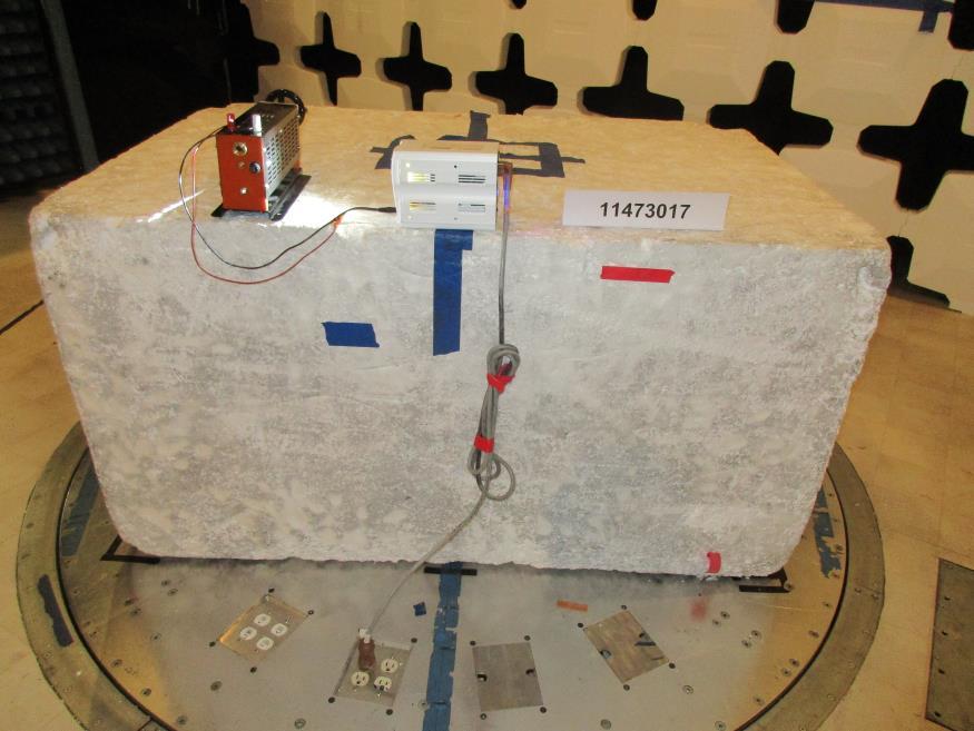
80 POLE-MOUNT FRONT BACK Page 80 of 97


81 AC MAINS LINE CONDUCTED EMISSIONS Table Top FRONT BACK Page 81 of 97


82 Pole-Mount FRONT BACK Page 82 of 97

83 AC MAINS HARMONIC CURRENT EMISSIONS AC MAINS LINE VOLTAGE FLUCTUATIONS AND FLICKER Page 83 of 97


84 8.2. IMMUNITY ELECTROSTATIC DISCHARGE TABLE TOP ESD POLE-MOUNT ESD Page 84 of 97


85 RADIATED IMMUNITY FRONT BACK Page 85 of 97


86 LEFT RIGHT Page 86 of 97


87 TOP BOTTOM Page 87 of 97

")
88 ELECTRICAL FAST TRANSIENT (AC MAINS) Page 88 of 97
 Page 89")
89 SURGE (AC MAINS) Page 89 of 97

")
90 RF CONDUCTED IMMUNITY (AC MAINS) Page 90 of 97


91 POWER FREQUENCY MAGNETIC FIELD IMMUNITY X ORIENTATION Y ORIENTATION Page 91 of 97

92 Z ORIENTATION POWERLINE VOLTAGE DIPS AND INTERRUPTIONS Page 92 of 97
FCC PART 15 CLASS B MEASUREMENT AND TEST REPORT. Tritech Technology Ltd.
 FCC PART 15 CLASS B MEASUREMENT AND TEST REPORT For Tritech Technology Ltd. Unit 8B,Chung pont Commercial Building No.300 Hennessy Road, Wanchai, HongKong Model: 0-545-24967-8, 0-545-24986-4 Report Type:
FCC Part 15 Subpart B Test Report. FCC PART 15 Subpart B Class B: 2014
 Shenzhen CTL Electromagnetic Technology Co., Ltd. Tel: +86-755-89486194 Fax: +86-755-26636041 FCC Part 15 Subpart B Test Report FCC PART 15 Subpart B Class B: 2014 Report Reference No...: CTL1408272147-F
Sensoray. Model 819. Tests Conducted by: ElectroMagnetic Investigations, LLC. May 10, 2013
 European Union (EU) Council Directive 2004/108/EC Electromagnetic Compatibility (EMC) and FCC Part 15 Subpart B Class B Test Report for Information Technology Equipment Sensoray Model 819 May 10, 2013
Test Report #: Date: January 24, 2006
 Test Report #: 2415-1 Date: January 24, 2006 CERTIFICATE #2316.01 Issued To: Jeffrey Samstad American Power Conversion 85 Rangeway Road North Billerica, MA 01862 USA 978-670-2440 Product Name/Description
Page: 1 of 19 EMC TEST REPORT EN55024:1998+A2:2003
 Page: 1 of 19 EMC TEST REPORT Reference No. Applicant : WT05110894 : Gembird Electronics Ltd. Equipment Under Test (EUT) : Product Name : Card reader Model No : USB2.0A LL-in-1 Standards : EN55022:1998+A2:2003
Test Report. Product Name: Access Point Model No.: MS-6809 FCC ID: DoC
 Test Report Product Name: Access Point Model No.: MS-6809 FCC ID: DoC Applicant : MICRO-STAR INT L Co., LTD Address : No 69, Li-De st., Jung-He City, Taipei Hsien, Taiwan, R.O.C Date of Receipt : June
CENTRE OF TESTING SERVICE INTERNATIONAL
 CENTRE OF TESTING SERVICE INTERNATIONAL OPERATE ACCORDING TO ISO/IEC 17025 IC TEST REPORT TEST REPORT NUMBER : CGZ3150202-00095-E A101,No.65,Zhuji Highway,Tianhe District,Guangzhou, Guangdong, China TEST
FCC PART MEASUREMENT AND TEST REPORT FOR. DongGuan City FLYSKY Remote Model Co., Ltd.
 FCC PART 15.249 MEASUREMENT AND TEST REPORT FOR DongGuan City FLYSKY Remote Model Co., Ltd. No.41 Road West, BanHu Village, HuangJiang Town, DongGuan City, GuangDong Porvince, China FCC ID: VPOFLYSKY002
FCC ID: IMK-ILCISA EMI TEST REPORT
 15.247 Certification FCC ID: IMK-ILCISA EMI TEST REPORT On SYMPHONY ISA Card Prepared for Proxim 295 N. Bernardo Ave Mountain View, CA 94043 Tel: (650)960-1630 Fax: (650)960-0332 Prepared by Electronic
TABLE OF CONTENTS 1. GENERAL INFORMATION PRODUCT DESCRIPTION FOR EQUIPMENT UNDER TEST (EUT) TEST STANDARDS TEST METHODOLOGY
 TEST STANDARDS TEST METHODOLOGY") FCC Rule(s): FCC Part 15B Measurement and Test Report Product Description: Tested Model: Report No.: For GlobTek, Inc. 186 Veterans Dr. Northvale, NJ 07647 USA FCC Part 15 Subpart B X-PLORE 8000 STANDARD
FCC Rule(s): FCC Part 15B Measurement and Test Report Product Description: Tested Model: Report No.: For GlobTek, Inc. 186 Veterans Dr. Northvale, NJ 07647 USA FCC Part 15 Subpart B X-PLORE 8000 STANDARD
FCC TEST REPORT for Aeon Labs LLC. Aeon Minimote Model No.: DS03202B-ZWUS, DS03202W-ZWUS
 Page 1 of 22 FCC TEST REPORT for Aeon Labs LLC. Aeon Minimote Model No.: DS03202B-ZWUS, DS03202W-ZWUS Prepared for Address Prepared By Address : Aeon Labs LLC. : 121 Buckingham drive, unit36 santa claras
Date: ESPOO Page: 1 (10) Appendices. Tyre Pressure Monitoring Device. Flextronics International Finland.
 Appendices. Tyre Pressure Monitoring Device. Flextronics International Finland.") TEST REPORT Date: ESPOO 25.04.2003 Page: 1 (10) Appendices Number: 1031681 No.1/1 Date of handing in: 07.04.2003 Testedby: Timo Leismala, Product Manager Reviewed by: Janne Nyman, Product Manager, EMC
TEST REPORT Date: ESPOO 25.04.2003 Page: 1 (10) Appendices Number: 1031681 No.1/1 Date of handing in: 07.04.2003 Testedby: Timo Leismala, Product Manager Reviewed by: Janne Nyman, Product Manager, EMC
TEST REPORT. iphone Hi-Fi Audio cable Adapter with Lightning female connector Model No.:
 No. 1 Workshop, M-10, Middle section, Science & Technology Park, Shenzhen, Guangdong, China 518057 Telephone: +86 (0) 755 2601 2053 Fax: +86 (0) 755 2671 0594 Email: ee.shenzhen@sgs.com Application No.:
FCC PART 15B, CLASS B TEST REPORT. Autel Intelligent Tech. Corp., Ltd.
 FCC PART 15B, CLASS B TEST REPORT For Autel Intelligent Tech. Corp., Ltd. 6th - 10th Floor, Bldg. B1, Zhiyuan, Xueyuan Rd., Xili, Nanshan Shenzhen China FCC ID: WQ8MAXISYSMY906 Report Type: Original Report
EMC Test Report. 850 Kacena Road Hiawatha, IA 52233
 EMC Client: EUT: Crystal Group 850 Kacena Road Hiawatha, IA 52233 Model RS112 No.: R20140819-21 Approved By: Nic S. Johnson, NCE EMC Test Engineering Manager/Technical Manager inarte Certified EMC Engineer
FCC TEST REPORT For. ETI Solid State Lighting (Zhuhai) Ltd. LED downlight Model No.: XX
 Ltd. LED downlight Model No.: XX") Page 1 of 24 FCC TEST REPORT For ETI Solid State Lighting (Zhuhai) Ltd LED downlight Model No.: 531931XX Prepared for Address Prepared by Address : ETI Solid State Lighting (Zhuhai) Ltd : No.1, Zhongzhu
Page 1 of 24 FCC TEST REPORT For ETI Solid State Lighting (Zhuhai) Ltd LED downlight Model No.: 531931XX Prepared for Address Prepared by Address : ETI Solid State Lighting (Zhuhai) Ltd : No.1, Zhongzhu
FCC Part 15B Test Report
 Shenzhen Toby Technology Co., Ltd. Report No.: TB-FCC111757 Page: 1 of 18 FCC Part 15B Test Report Application No. : TB11081419 Applicant : Ingtron Enterprise Co., Ltd. Equipment Under Test (EUT) EUT Name
Sunlight Supply, Inc.
 FCC Part 18 Subpart C Consumer For RF Lighting Equipment Electromagnetic Compatibility Test Report Sunlight Supply, Inc. Etelligent Compatible Ballast - olt July 19, 2017 Tests Conducted by:, LLC 20811
Test Report. Model No.: NF592XX-YYYY-ZZ(X,Y & Z: Stands for A-Z & 0-9 ) HBJC1XXF592-YYYY-ZZ (X,Y & Z: Stands for A-Z & 0-9 )
 HBJC1XXF592-YYYY-ZZ (X,Y & Z: Stands for A-Z & 0-9 )") Test Report Applicant: Product Name: Brand Name: Jetway Information Co.,Ltd Motherboard/Barebone N/A Model No.: NF592XX-YYYY-ZZ(X,Y & Z: Stands for A-Z & 0-9 ) HBJC1XXF592-YYYY-ZZ (X,Y & Z: Stands for
Test Report Applicant: Product Name: Brand Name: Jetway Information Co.,Ltd Motherboard/Barebone N/A Model No.: NF592XX-YYYY-ZZ(X,Y & Z: Stands for A-Z & 0-9 ) HBJC1XXF592-YYYY-ZZ (X,Y & Z: Stands for
FCC PART TEST REPORT. HHC Changzhou Corp.
 FCC PART 15.249 TEST REPORT For HHC Changzhou Corp. No 61, Xinggang Road, Zhonglou District, Changzhou, Jiangsu, China, 213023 FCC ID: 2AEQWCB20HHC011 Report Type: Original Report Product Type: Control
CONTENTS 6.2 TEST SET-UP...16
 CONTENTS 1. GENERAL INFORMATION...3 2. INTRODUCTION...4 3. PRODUCT INFORMATION...5 3.1 DESCRIPTION OF EUT...5 3.2 SUPPORT EQUIPMENT / CABLES USED...6 3.3 MODIFICATION ITEM(S)...6 4. DESCRIPTION OF TESTS...7
Report On. FCC Testing of the Pace Plc 16x4 Hybrid Gateway Cable Set Top Box COMMERCIAL-IN-CONFIDENCE
 Report On FCC Testing of the Pace Plc 16x4 Hybrid Gateway Cable Set Top Box Document 75926325 Report 01 Issue 1 April 2014 TÜV SÜD Product Service, Octagon House, Concorde Way, Segensworth North, Fareham,
CENTRE OF TESTING SERVICE INTERNATIONAL OPERATE ACCORDING TO ISO/IEC FCC ID TEST REPORT
 CENTRE OF TESTING SERVICE INTERNATIONAL OPERATE ACCORDING TO ISO/IEC 17025 FCC ID TEST REPORT TEST REPORT NUMBER : CGZ3150520-00565-EF TEST REPORT For FCC ID 47 CFR PART 15 OCT, 2014 Report Reference No....
FCC Report. Beijing Visual World Technology Co.,Ltd.
 FCC Report Report No.: GTS201703000097F01 Applicant: Beijing Visual World Technology Co.,Ltd. Address of Applicant: 15th Floor and 17th Floor 1701-10A, Building 3, No. 10, Jiuxianqiao Road Jia, Chaoyang
Testing. Maker Works. Applicant: Model No.: FCC ID: Jun., May to 16. Date of Test: PASS* Test Result: Signature: Authorized. this report.
 1 Cover Page Shenzhen Zhongjian Nanfang Testing Co., Ltd. FCC REPORT Applicant: Address of Applicant: Maker Works Technology INC Building C3, Floor 4th, Zhiyuan, Xili, Nanshan District, ShenZhen 518057
R&TTE EMC TEST REPORT
 No. 1 Workshop, M-10, Middle section, Science & Technology Park, Shenzhen, Guangdong, China 518057 Telephone: +86 (0) 755 2601 2053 Fax: +86 (0) 755 2671 0594 Email: sgs_internet_operations@sgs.com Application
FCC PART 15 CLASS B EMI MEASUREMENT AND TEST REPORT
 FCC PART 15 CLASS B EMI MEASUREMENT AND TEST REPORT For XIAMEN YEALINK NETWORK TECHNOLOGY CO., LTD. 7/F HuaLian Electronic BLDG., No.580 JiaHe Road, XiaMen, China September 26, 2005 This Report Concerns:
T E S T - R E P O R T. No for. SLG 42 MOBY Component
 Straubing, August 04, 1998 T E S T - R E P O R T No. 51905-80643-0 for SLG 42 MOBY Component Applicant: Purpose of Testing: Siemens AG To show compliance with FCC Rules Part 15, Subpart C section 15.209
Report No. 074L076-RFCEP02V01-A. Test Report MSI / MS-6837D
 Test Report Product Name Model No. Transmitter Module Notebook MS-16371,MS-16372 Atheros / AR5BXB63 MSI / MS-6837D Applicant MICRO-STAR INT L Co., LTD. Address No. 69, Li-De St., Jung-He City, Taipei Hsien,
Report No R-RFCEP02V01. Test Report. MICRO-STAR INT L Co., LTD. No. 69, Li-De St., Jung-He City, Taipei Hsien, Taiwan, R.O.C.
 Test Report Product Name Model No. Notebook MS-1242, U200 Transmitter Module. Ralink / RT3090 (MS-6891) Bluetooth Module MSI / MS-6837D Applicant Address MICRO-STAR INT L Co., LTD. No. 69, Li-De St., Jung-He
CONTENTS 1. GENERAL INFORMATION INTRODUCTION PRODUCT INFORMATION DESCRIPTION OF TESTS CHANNEL BANDWIDTH...
 Test Report Number : GETEC-E3-09-083 Page 2 / 33 CONTENTS. GENERAL INFORMATION...4 2. INTRODUCTION...5 3. PRODUCT INFORMATION...6 3. DESCRIPTION OF EUT...6 3.2 SUPPORT EQUIPMENT / CABLES USED...7 3.3 MODIFICATION
Order Number : GETEC-C FCC Part 15 subpart B Test Report Number : GETEC-E Page 2 / 32 CONTENTS
 Test Report Number : GETEC-E3-12-032 Page 2 / 32 CONTENTS 1. GENERAL INFORMATION... 3 2. INTRODUCTION... 4 3. PRODUCT INFORMATION... 5 3.1 DESCRIPTION OF EUT... 5 3.2 SUPPORT EQUIPMENT / CABLES USED...
Report No R-RFCEP02V01. Test Report MSI / MS-6837D. Date of Receipt Aug. 21, Issued Date Sep. 11, 2007
 Test Report Product Name Model No. Transmitter Module Notebook MS-163D, EX610 Atheros / AR5BXB63 MSI / MS-6837D Applicant Address MICRO-STAR INTL Co., LTD. No. 69, Li-De St., Jung-He City, Taipei Hsien,
Report No. 074L146-RFCEP02V01. Test Report MSI / MS-6837D. Date of Receipt Apr. 24, Issued Date May. 28, 2007
 Test Report Product Name Model No. Transmitter Module Notebook MS-16342 Atheros / AR5BXB63 MSI / MS-6837D Applicant Address MICRO-STAR INTL Co., LTD. No. 69, Li-De St., Jung-He City, Taipei Hsien, Taiwan,
FCC Report (WIFI) Shenzhen Reo-link Digital Technology Co., Ltd B509, University Town Business Park LiShan Road, NanShan, Shenzhen, Guangdong, China
 Shenzhen Reo-link Digital Technology Co., Ltd B509, University Town Business Park LiShan Road, NanShan, Shenzhen, Guangdong, China") FCC Report (WIFI) Applicant: Address of Applicant: Manufacturer/y: Address of Manufacturer/y: Equipment Under Test (EUT) Product Name: Shenzhen Reo-link Digital Technology Co., Ltd B509, University Town
FCC Report (WIFI) Applicant: Address of Applicant: Manufacturer/y: Address of Manufacturer/y: Equipment Under Test (EUT) Product Name: Shenzhen Reo-link Digital Technology Co., Ltd B509, University Town
FCC test report. Via Pezza Alta, 13 I Rustignè di Oderzo (TV)
") Test report nr. 20811FCC11 Measurements performed in accordance with: FCC Rules: code of Federal Regulations (CFR) no. 47 PART 15 RADIO FREQUENCY DEVICES Product: Tested model: FCC ID Applicant: Manufacturer:
Test report nr. 20811FCC11 Measurements performed in accordance with: FCC Rules: code of Federal Regulations (CFR) no. 47 PART 15 RADIO FREQUENCY DEVICES Product: Tested model: FCC ID Applicant: Manufacturer:
Page: 1 of 15 FCC TEST REPORT. : MEGAVIEW DIGITECH LIMITED : C Fu Gui Yuan, Block 80, Bao an District, Shenzhen, China
 Page: 1 of 15 FCC TEST REPORT Reference No. Applicant Address : WT10125265-S-E-F : MEGAVIEW DIGITECH LIMITED : C1-1001 Fu Gui Yuan, Block 80, Bao an District, Shenzhen, China Equipment Under Test (EUT)
Shenzhen Zhongjian Nanfang Testing Co., Ltd.
 Report No: CCIS15010007003 1 Cover Page FCC REPORT Applicant: Address of Applicant: Interglobe Connection Corp 7500 NW 25 th Street 112 Miami, Florida 33122 USA Equipment Under Test (EUT) Product Name:
APPLICATION OF CERTIFICATION For. TTE Technology Inc. LCD TV FCC ID: W8ULE32HDE3000
 FCC ID:W8ULE32HDE3000 APPLICATION OF CERTIFICATION For TTE Technology Inc. LCD TV Brand Name TCL Model Number LE32HDE3000; LE32HDE3011 LE32HDE5311; LE32HDF3310TA LE32HDF3311; LE32HDF3312 FCC ID: W8ULE32HDE3000
FCC Report (WIFI) Shenzhen SDMC Technology Co., Ltd 2AFC2-STB-1HD. * In the configuration tested, the EUT complied with the standards specified above.
 Shenzhen SDMC Technology Co., Ltd 2AFC2-STB-1HD. * In the configuration tested, the EUT complied with the standards specified above.") Report No.: GTSE15080158301 FCC Report (WIFI) Applicant: Shenzhen SDMC Technology Co., Ltd Address of Applicant: 7/F, W2-A Bld, Gaoxin S. Av. 4, Hi-tech Park, Nanshan, Shenzhen, China Equipment Under Test
Report No.: GTSE15080158301 FCC Report (WIFI) Applicant: Shenzhen SDMC Technology Co., Ltd Address of Applicant: 7/F, W2-A Bld, Gaoxin S. Av. 4, Hi-tech Park, Nanshan, Shenzhen, China Equipment Under Test
FCC REPORT Q6WBT * In the configuration tested, the EUT complied with the standards specified above.
 1 Cover Page Report No: CCIS12110026101 FCC REPORT Applicant: Address of Applicant: Equipment Under Test (EUT) GUANGDONG STEELMATE SECURITY CO., LTD Renan Street, Dong fu Road, Dongfeng Town,Zhongshan,
CHAO WEI ELECTRONICS CO., LTD. FCC REPORT CHAO WEI ELECTRONICS CO., LTD.
 CHAO WEI ELECTRONICS CO., LTD. FCC REPORT Prepared For : CHAO WEI ELECTRONICS CO., LTD. No.8, Xianglong Road, Xiagang, Changantown, Dongguan City, China Product Name: Model : DVB-T ANTENNA CW-DVB66, CW-DVB83,
EMC REPORT. Shenzhen Sunchip Technology Co., Ltd. * In the configuration tested, the EUT complied with the standards specified above.
 Report No.: GTS16000346E01 EMC REPORT Applicant: Shenzhen Sunchip Technology Co., Ltd Address of Applicant: 201-301, Building A4, No. 90, Dayang Road, FuYong town, Bao'an District, Shenzhen, China Equipment
FCC Report (WIFI) Red Bear Company Limited. RedBear IoT phat 2ABXJ-PHAT-IOT
 Red Bear Company Limited. RedBear IoT phat 2ABXJ-PHAT-IOT") Report No.: GTS201607000065E01 FCC Report (WIFI) Applicant: Red Bear Company ed Address of Applicant: 1711 Block B, Wah Luen Industrial Centre, 15-21 Wong Chuk Yeung Street, Fo Tan, Hong Kong Equipment
Report No.: GTS201607000065E01 FCC Report (WIFI) Applicant: Red Bear Company ed Address of Applicant: 1711 Block B, Wah Luen Industrial Centre, 15-21 Wong Chuk Yeung Street, Fo Tan, Hong Kong Equipment
FCC Test Report. Color LCD Monitor
 Underwriters Laboratories Inc. www.ul.com/emc www.ulk.co.kr Project: 10CA46552 File: TC8352 Report: 10CA46552-FCC Date: October 13, 2010 Model: EX190W (Basic), RadiForce EX190W FCC Test Report For Color
TEST REPORT. Power Spout PLT V. tested to. 47 Code of Federal Regulations. Part 15 - Radio Frequency Devices
 EMC Technologies (NZ) Ltd PO Box 68-307,Newton Auckland 1145 New Zealand Phone 09 360 0862 Fax 09 360 0861 E-Mail Address: aucklab@ihug.co.nz Web Site: www.emctech.com.au TEST REPORT Power Spout PLT 100
EMC Test Report. Client: Crestron Electronics, Inc. Tested by: Jeremy O. Pickens, Senior EMC Engineer
 Test Report Number: 3919823EMC1 Rev. Page: 1 of 26 EMC Test Report Project Number: 3919823 Report Number: 3919823EMC1 Revision Level: Client: Crestron Electronics, Inc. Equipment Under Test: infinet EXTM
ONETECH Testing & Eval. Lab. VERIFICATION FCC RULES PARTS 2 & 15 CLASS A DIGITAL DEVICE. for AUTHORIZED. Win4NET Co., Ltd.
 ONETECH Testing & Eval. Lab. VERIFICATION FCC RULES PARTS 2 & 15 CLASS A DIGITAL DEVICE for PRODUCT: VIDEO CODEC MODEL NAME: NetSafe-VC3001 AUTHORIZED Win4NET Co., Ltd. KOLON Digital Tower 1301, 222-7,
STC (Dongguan) Company Limited EC VERIFICATION OF COMPLIANCE EMC-D163584VOC
 Company Limited EC VERIFICATION OF COMPLIANCE EMC-D163584VOC") EC VERIFICATION OF COMPLIANCE Reference Number: Applicant: EMC-D16584VOC Zhuhai Zhi Li Battery Co., Ltd. 7/F., Building 10, Xiang Zhou North Industry Park, Zhuhai, GD 519002, China Description: Zinc Air
EC VERIFICATION OF COMPLIANCE Reference Number: Applicant: EMC-D16584VOC Zhuhai Zhi Li Battery Co., Ltd. 7/F., Building 10, Xiang Zhou North Industry Park, Zhuhai, GD 519002, China Description: Zinc Air
FCC PART TEST REPORT SHANGHAI MERIT TECHNOLOGY CORP.
 FCC PART 15.247 TEST REPORT For SHANGHAI MERIT TECHNOLOGY CORP. 1058 TAOGAN RD., SHESHAN TOWN, SONGJIANG DISTRICT, SHANGHAI, China FCC ID: XJ6MT-180H Report Type: Original Report Product Type: 4CH 2.4GHZ
A Test Lab Techno Corp. FCC. RF Test Report. Product Type. : Mobile Hotspot. Applicant. : Netgear Inc.
 FCC RF Test Report Product Type Applicant : Mobile Hotspot : Netgear Inc. Address : 350 East Plumeria Drive, San Jose, CA 95134 Trade Name Model Number Test Specification : NETGEAR : AC810S-300 : FCC 47
EMC Test Report. Client: Continental Automotive Systems, Inc. Tested by: Fendy Liauw, Engineering Technician
 Test Report Number: 3953917EMC7 Rev: Page: 1 of 35 EMC Test Report Project Number: 3953917 Report Number: 3953917EMC7 Revision Level: Client: Continental Automotive Systems, Inc. Equipment Under Test:
FCC Test Report (Class II Permissive Change)
") FCC Test Report (Class II Permissive Change) Product Name Intel Wireless-AC 9560 Model No. 9560NGW FCC ID. 2AKHF9560NG Applicant TONGFANG HONGKONG (SUZHOU) LIMITED Address NO. 83 Wu Lane, Suzhou Industrial
FCC Test Report (Class II Permissive Change) Product Name Intel Wireless-AC 9560 Model No. 9560NGW FCC ID. 2AKHF9560NG Applicant TONGFANG HONGKONG (SUZHOU) LIMITED Address NO. 83 Wu Lane, Suzhou Industrial
FCC TEST REPORT D-LINK CORPORATION
 FCC TEST REPORT REPORT NO.: RF921014R02 MODEL NO.: DWL-120(refer to page 6 for other models) RECEIVED: October 14, 2003 TESTED: October 16 ~ October 17, 2003 APPLICANT: ADDRESS: D-LINK CORPORATION NO.8,
ELECTRICAL TESTING FOR:
 ELECTRICAL TESTING 0839.01 Hermon Laboratories Ltd. Harakevet Industrial Zone, Binyamina 30500, Israel Tel. +972-4-6288001 Fax. +972-4-6288277 E-mail: mail@hermonlabs.com TEST REPORT ACCORDING TO: FCC
EMC TEST REPORT. Product : Digital Camcorder Model No. : SCD5000. SAMSUNG ELECTRONICS Co., Ltd. EMC Test Laboratory. Project No.
 Page 1 of 17 EMC TEST REPORT Project No. :LBE031059 Product : Digital Camcorder Model No. : SCD5000 Date of test : May 7 ~ 9, 2003 Issued Date : May 9, 2003 Tested by: Jay Yong, PARK / Test Engineer Reviewed
CERTIFICATION APPLICATION TEST REPORT
 BEC INCORPORATED CERTIFICATION APPLICATION TEST REPORT TEST STANDARDS: FCC Part 15 Subpart C, Section 15.247 Intentional Radiator ARRIS Model VMS4100 Set Top Box FCC ID: ACQ-VMS4100 REPORT BEC-1792-03
FCC Part 15 Certification Test Report. 433 MHz Alarm System
 FCC Part 15 Certification Test Report 433 MHz Alarm System FCC ID: Q6K 1000-7253 FCC Rule Part: 15.231 ACS Report Number: 03-0111-15B Manufacturer: 3SI Security Systems Model: 1000-7253 with variants Test
Test result 1. Conducted emission EN 55022: A1:2007 EA 3 passed 2. Radiated emission <1GHz (others)
") SHARP EMC Testing Laboratory Test Report No.: 11/250-02 page TR-2 of TR-13 5 SUMMARY OF TEST RESULTS Emission testing No. Item Test procedure Page code Number of pages Test result 1. Conducted emission
SHARP EMC Testing Laboratory Test Report No.: 11/250-02 page TR-2 of TR-13 5 SUMMARY OF TEST RESULTS Emission testing No. Item Test procedure Page code Number of pages Test result 1. Conducted emission
T E S T - R E P O R T. No for PC24E-11-FC/R. RF-modem for wireless LAN. Agere Systems Nederland B.V.
 EMV-Prüfzentrum EMI/EMC-Testcenter Straubing, September 5, 2001 T E S T - R E P O R T No. 56305-10552-1 for RF-modem for wireless LAN Purpose of testing: To show compliance with FCC Code of Federal Regulations,
FCC PART 22H, PART 24E MEASUREMENT AND TEST REPORT. Shanghai AirM2M Communication Technology Co., Ltd
 FCC PART 22H, PART 24E MEASUREMENT AND TEST REPORT For Shanghai AirM2M Communication Technology Co., Ltd No. 666.East beijing road, Shanghai, China FCC ID: 2AEGG-AIR208 Report Type: Original Report Product
TEST REPORT. Test Report No. : UL-RPT-RP C V2.0. Date of Issue: 06 March 2018
 Test Report No. : UL-RPT-RP11913492-2216C V2.0 Manufacturer : Raspberry Pi (Trading) Ltd Model No. : Raspberry Pi 3 Model B+ FCC ID : 2ABCB-RPI3BP Technology : Bluetooth Low Energy Test Standard(s) : FCC
TEST REPORT FROM RFI GLOBAL SERVICES LTD
 TEST REPORT FROM RFI GLOBAL SERVICES LTD Test of: D-MINI-2108-2019 FCC ID: NEO-DMINI21082019 To: FCC Parts 2.1046; 2.1049; 22.913(a); 22.917; 24.232; 24.238 & 15.107 3GPP TS 36.143 V10.3.0 This Test Report
e2b calibration 521 Fifth Avenue Chardon, Ohio Phone: Fax: Certificate Of Calibration
 e2b calibration certifies that the above listed instrument at the time of calibration meets or exceeds all specifications as stated in the referenced procedure (unless otherwise noted). It has been calibrated
Specifications. Reference Documentation. Performance Conditions
 The material in this section is organized into two main groupings: the specification tables and the supporting figures. The specification tables include: 1. PAL general and test signal specifications 2.
Report No. 103S085E-RFCEP02V01-A. Test Report
 Test Report Product Name Notebook Model No. MS-1244 Transmitter Module. Ralink / RT3090 (MS-6891) luetooth Module MSI / MS-6837D Applicant Address MICRO-STAR INT L Co., LTD. No. 69, Li-De St., Jung-He
TEST REPORT. Test Report No. : UL-RPT-RP JD18L V2.0. Manufacturer : Neeo AG. Model No. : 6336-BRAIN FCC ID : 2AKK7-BR633601
 TEST REPORT Test Report No. : UL-RPT-RP11456397JD18L V2.0 Manufacturer : Neeo AG Model No. : 6336-BRAIN FCC ID : 2AKK7-BR633601 Test Standard(s) : FCC Part 15.207 1. This test report shall not be reproduced
Noise Detector ND-1 Operating Manual
 Noise Detector ND-1 Operating Manual SPECTRADYNAMICS, INC 1849 Cherry St. Unit 2 Louisville, CO 80027 Phone: (303) 665-1852 Fax: (303) 604-6088 Table of Contents ND-1 Description...... 3 Safety and Preparation
Improving the accuracy of EMI emissions testing. James Young Rohde & Schwarz
 Improving the accuracy of EMI emissions testing James Young Rohde & Schwarz Q&A Who uses what for EMI? Spectrum Analyzers (SA) Test Receivers (TR) CISPR, MIL-STD or Automotive? Software or front panel?
THRU Lab & Engineering , Hager-Ri, Yoju-Up, Yoju-Gun Kyunggi-Do, , Korea T /F
 Test Report Product Name: IQ Pager (Receiver) FCCID: WDC-IQ2008 Model No.: IQ2008 Applicant: HME Wireless, Inc. 1400 Northbrook Parkway, Suite 320, Suwanee City, GA, 30024, U.S.A Date Receipt : 12/20/2008
TEST REPORT FROM RFI GLOBAL SERVICES LTD
 FROM RFI GLOBAL SERVICES LTD Test of: Blighter B422-HPNB Aux Unit FCC ID: UFQB400HPNBAUX To: FCC Part 90: 2010 Subpart F in accordance with RFI Test Plan RFI/REGE1/TP75565JD03 Test Report Serial No: RFI-RPT-RP76945JD15B
3500/42E Vibration Monitor
 3500/42E Vibration Monitor Bently Nevada* Asset Condition Monitoring Description The 3500/42E Vibration Monitor is a 4-channel monitor that accepts input from proximity and seismic transducers, conditions
THRU Lab & Engineering , Hager-Ri, Yoju-Up, Yoju-Gun Kyunggi-Do, , Korea T /F
 Test Report Product Name: IQ Pager (Receiver) FCCID: WDC-IQ2008 Model No.: IQ2008L Applicant: HME Wireless, Inc. 1400 Northbrook Parkway, Suite 320, Suwanee City, GA, 30024, U.S.A Date Receipt : 12/20/2008
Test Report. Product Name : PC2PC-Bluetooth Model No. : MS-6967 FCC ID. : I4L-MS6967
 Test Report Product Name : PC2PC-Bluetooth Model No. : MS-6967 FCC ID. : I4L-MS6967 Applicant : MICRO-STAR INT'L Co., LTD. Address : No. 69, Li-De St, Jung-He City, Taipei Hsieh, Taiwan, R.O.C. Date of
Fibre Optic Modem ODW-622
 Fibre Optic Modem ODW-622 RS-232 to fibre optic link, redundant ring or multidrop applications The ODW-622 can be used to create either redundant ring or multidrop solutions for devices with RS-232 interfaces.
LONWORKS Fibre Optic Converter
 LONWORKS Fiber Optic Converter LRW-102 and LRW-102/PP LONWORKS to fibre optic link, multidrop and redundant ring applications The LRW-102 is a fibre optic modem designed for multidrop and redundant ring
Raspberry Pi (Trading) Ltd. Raspberry Pi. dated. 9th December 2013
 Ltd. Raspberry Pi. dated. 9th December 2013") FCC ID: 2ABCB-RPI2 T545 of 37 EMC Testing ---------- ( Cambridge Ltd. ) ---------- EMC Consultancy EMC Training 23, Headington Drive, Cambridge. CB 9HE Tel : 0954 25974 (test site) or : 0223 2440 (accounts)
FCC ID: 2ABCB-RPI2 T545 of 37 EMC Testing ---------- ( Cambridge Ltd. ) ---------- EMC Consultancy EMC Training 23, Headington Drive, Cambridge. CB 9HE Tel : 0954 25974 (test site) or : 0223 2440 (accounts)
FCC Test Report (Class II Permissive Change)
") FCC Test Report (Class II Permissive Change) Product Name 802.11abgn/11ac WLAN + Bluetooth PCI-E Mini Card Model No BCM94360HMB FCC ID QDS-BRCM1082 Applicant Broadcom Corporation Address 190 Mathilda Place
FCC Test Report (Class II Permissive Change) Product Name 802.11abgn/11ac WLAN + Bluetooth PCI-E Mini Card Model No BCM94360HMB FCC ID QDS-BRCM1082 Applicant Broadcom Corporation Address 190 Mathilda Place
SEL-3405 High-Accuracy IRIG-B Fiber-Optic Transceiver
 SEL-3405 High-Accuracy IRIG-B Fiber-Optic Transceiver Accurate IRIG-B Over Fiber Optics Major Features and Benefits The SEL-3405 High-Accuracy IRIG-B Fiber-Optic Transceiver can send high-accuracy demodulated
FCC PART 15C TEST REPORT FOR CERTIFICATION On Behalf of NYNE MULTIMEDIA INC. Bluetooth Speaker. Model Number: NYNE VIBE FCC ID: AWA-NYNEVIBE
 FCC PART 15C TEST REPORT FOR CERTIFICATION On Behalf of NYNE MULTIMEDIA INC. Bluetooth Speaker Model Number: NYNE VIBE FCC ID: AWA-NYNEVIBE Prepared for: NYNE MULTIMEDIA INC. 3451 LUNAR COURT, OXNARD,
ODW-621. RS-232 Point-to-point applications
 Re-timing Data rate up to 250 kbit/s 9-position D-sub connector Redundant power supply inputs Status interface for fault indication Fibre link fault indication (Red) Design for harsh environments 40 to
Fibre Optic Modem ODW-611
 Fibre Optic Modem ODW-611 PROFIBUS DP to fibre optic link, point-to-point applications The ODW-611 is a fibre optic modem designed for point-to-point fibre optic connections between PROFI- BUS DP networks.
FCC REPORT. Report Reference No... : TRE R/C.: Simbans Picasso 10 Inch Tablet
 FCC REPORT Report Reference No.... : TRE1704011605 R/C.:59884 FCC ID... : Applicant s name... : Address... : Manufacturer...: Address...: Test item description... : Trade Mark... : Model/Type reference...
LONWORKS Fibre Optic Router
 LONWORKS Fiber Optic Router LRW-112 and LRW-112/PP LONWORKS to fibre optic link, multidrop and redundant ring applications The LRW-112 router offers an easy way to extend the distance between LONWORKS
Single output models feature wide-range output adjustability to meet a wide variety of standard and user-specific output voltage requirements.
 RoHS Lead-Solder-Exemption Compliant New 3.3 V and 5 V Output Models Universal Input 85-264 VAC Industry-Standard Footprint: 7.0" x 4.3" x 1.97" (177.8 x 109.2 x 50.0 mm) Input Transient & ESD Compliance
Shenzhen Zhongjian Nanfang Testing Co., Ltd.
 Report No: CCIS3667. Cover page FCC REPORT (Mobile Phone) Applicant: Address of Applicant: Equipment Under Test (EUT) NETLET ELECTRONICS (HONG KONG) LIMITED 2/F., San Toi Building,37-39 Connaught Road
Advantys STB DATA SHEET. Advantys STB Output Module. Description. Features
 Advantys STB Advantys STB Output Module DATA SHEET Description The Advantys model STBDAO5260 Digital Output Module provides 2 isolated discrete output points that operate on a 115 VAC power source. The
Agilent 87405C 100 MHz to 18 GHz Preamplifier
 Agilent 8745C 1 MHz to 18 GHz Preamplifier Technical Overview Key Features Rugged, portable design for ease of use in the field Probe-power bias connection eliminates the need for an additional power supply
JD725A Cable and Antenna Analyzer - Dual Port
 COMMUNICATIONS TEST & MEASUREMENT SOLUTIONS JD725A Cable and Antenna Analyzer - Dual Port Key Features Portable and lightweight handheld instrument Built-in wireless frequency bands as well as the most
Fibre optic router for TP/FT-10 LRW-112PP
 Fibre optic router for TP/FT-10 LRW-112PP Lo n Wo r k s to fibre optic link, point-to-point applications The LRW-112PP router offers an easy way to extend the distance between LONWORKS 78 kbit/s TP/FT
MAP110 AC-DC Series Data Sheet
 Description Single-Output Model Selection VOLTAGE RANGE OUTPUT CURRENT OUTPUT CURRENT REGULATION REGULATION %p-p (NOTE 1) ACCURACY MAP110-1005 5V 4.95V to 5.50 16A 2 0.2% 1% 1% 5.09V to 5.11V MAP110-1012
ATT AN TENG TESTING R& TTE TEST REPORT. For Electric Skateboard Surfwheel. Test Report Number: ATT RT
 TT N TENG TESTING R& TTE TEST REPORT For Electric Skateboard Surfwheel R1 Trademark: Surfwheel Test Report Number: TT1605230089RT Issued Date: June 02, 2016 Issued for: Koofy Development Limited Unit 220
PAM-1840 Preamplifier Operation Manual
 PAM-1840 Preamplifier Operation Manual 1 TABLE OF CONTENTS INTRODUCTION 3 GENERAL INFORMATION 4 SPECIFICATIONS 4 OPERATING INSTRUCTIONS 5 MAINTENANCE 6 2 INTRODUCTION BEFORE APPLYING POWER Review this
R&S RT-Zxx High-Bandwidth Probes Specifications
 R&S RT-Zxx High-Bandwidth Probes Specifications Test & Measurement Data Sheet 14.00 CONTENTS Definitions... 3 Probe/oscilloscope chart... 4 R&S RT-ZZ80 transmission line probe... 5 R&S RT-ZS10/-ZS10E/-ZS20/-ZS30
TEST REPORT. Report Number: MPK-003B Project Number: G October 20, 2017
 TEST REPORT Report Number: 13224477MPK-3B Project Number: G13224477 October 2, 217 Testing performed on the FIBERGATEWAY Model Number: GR24BG FCC ID: 2ACJF-FGW-GR24BG to FCC Part 15, Subpart E For Altice
Indoor Linear 80W Driver SI-C215280N2KR
 Product Data Sheet Rev.00 2017. 2. 9 1# LED Driver Indoor Linear 80W Driver SI-C215280N2KR Constant Current LED Driver Features & Benefits Output Current Range: 1550mA Output Voltage Range: MAX 51 Vdc
Multifunction Digital Timer
 Multifunction Digital Timer 72 x72 mm Timer with Easy-to-use Functions Nine output modes accommodate a wide variety of applications. All parameters set by scroll-through menus accessed from the front panel.
REPORT Datum/Date Beteckning/Reference Sida/Page
 2002-10-25 F219009-F24 1 (1) FCC ID: B5KPROJ1192211-1 Rev. 2003-01-16 Encl. 1 Description - Equipment Under Test (EUT) Equipment: Tx Frequency range: Tested Channel: WCDMA Base station transceiver 1900
CERTIFICATION APPLICATION TEST REPORT
 BEC INCORPORATED CERTIFICATION APPLICATION TEST REPORT TEST STANDARDS: FCC Part 15 Subpart C, Section 15.247 Intentional Radiator ARRIS Model VMS4100 Set Top Box FCC ID: ACQ-VMS4100 REPORT BEC-1792-02
DATA SHEET. The Advantys model STBDAI5260 Digital Input Module provides 2 isolated discrete input points that operate on a 115 VAC power source.
 Advantys STB Advantys STB Input Module DATA SHEET Description The Advantys model STBDAI5260 Digital Input Module provides 2 isolated discrete input points that operate on a 115 VAC power source. Features