LED Array Board.
|
|
|
- Harry Bruce
- 6 years ago
- Views:
Transcription


1 LED Array Board EB087
2 Contents About This Document 2 General Information 3 Board Layout 4 Testing This Product 5 Circuit Description 6 Circuit Diagram 7 About This Document This document concerns the E-blocks LED Array board with code EB087 version 1. The order code for the LED Array board product is EB Trademarks and copyright PIC and PICmicro are registered trademarks of Arizona Microchip Inc. E-blocks is a trademark of Matrix Technology Solutions Ltd. 2. Disclaimer The information provided within this document is correct at the time of going to press. Matrix TSL reserves the right to change specifications from time to time. 3. Testing this product It is advisable to test the product upon receiving it to ensure it works correctly. Matrix provides test procedures for all E-blocks, which can be found in the Support section of the website. 4. Product support If you require support for this product then please visit the Matrix website, which contains many learning resources for the E-blocks series. On our website you will find: How to get started with E-blocks - if you are new to E-blocks and wish to learn how to use them from the beginning there are resources available to help. Relevant software and hardware that allow you to use your E-blocks product better. Example files and programs. Ways to get technical support for your product, either via the forums or by contacting us directly. 2 Copyright
3 General Information 1. Description The LED Array board allows the exploration of basic display control mechanisms. The board features an 8 by 5 LED matrix where each LED has its own buffer to maintain the state. Each LED buffer output is connected to the input of the next meaning that data cascades from one LED to the next starting from LED D0 and running through to LED D40. Multiple LED Array boards can be connected together to form a longer LED chain. Fitting the boards to a 20mm pitch E-blocks backplane allows a constant spaced message board type display to be created. The current for all of the LEDs is passed through a MOSFET which allows the LED s brightness to be controlled or switched off when idle to save power. The display interface is capable of handling very high speed data allowing large display boards with high frame rate animations or scrolling text to be created. 2. Features 40 Bright Red LEDs 8 rows x 5 columns 40 Digital Logic Buffers Master Brightness Control No Complicated Software Multiplexing Required Overvoltage Protection Circuit Inter-connectable to allow much larger displays to be created V system compatibility The board is compatible with 3.3V and 5V systems. 4. Block Diagram 3 Copyright
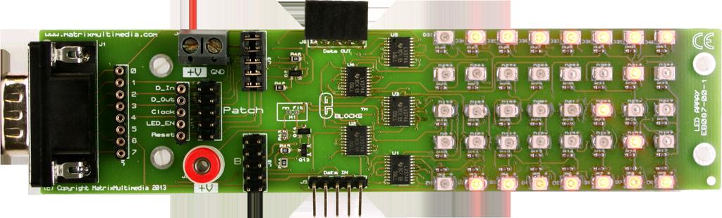
4 Board Layout ) 9 Way D-type Plug 2) Patch system 3) Input supply voltage screw terminals 4) +V 2mm Socket 5) LED Control MOSFET Circuit 6) Overvoltage Protection Circuit 7) Data Out Expansion Socket 8) Data In Expansion Socket 9) Octal Buffer IC Controlling Colum 1 - LEDs D1 D8 10) Octal Buffer IC Controlling Colum 2 - LEDs D9 D16 11) Octal Buffer IC Controlling Colum 3 - LEDs D17 D24 12) Octal Buffer IC Controlling Colum 4 - LEDs D25 D32 13) Octal Buffer IC Controlling Colum 5 - LEDs D33 D40 14) LED D1 15) LED D8 16) LED D33 17) LED D40 4 Copyright
5 Testing This Product The following program will test the operation of the LED Array E-block. The test file can be downloaded from com. 1. System Setup (Optional) Sensors board EB003 (Optional) Additional working EB087 LED Array Block Multi-programmer board (EB006) with: EB006 Options Power supply PICmicro device SW1 (Fast/Slow) SW2 (RC/Xtal) Xtal frequency Port A Port B Port C Port D Port E Test program Setting External, 14V 16F877A Fast Xtal MHz Sensors board EB003 LED Array board EB087 LED_Array_2.hex 1 Ensure that the Multiprogrammer is in correct configuration. - Fast mode (SW1 towards the center of the board). - XTAL mode (SW2 towards the center of the board). - Ensure that a MHz crystal is inserted in the Multiprogrammer board. 2 Insert the Sensors board (EB003) into Port A of the Multiprogrammer. 3 Connect wire from +V of Sensors board to +V of Multiprogrammer. 4 Connect a 12V PSU to the EB006 and power up. 5 Program the a PIC16F877A with the test program LED_Array_2.hex. 6 Disconnect PSU. 7 Plug the known working EB087 Data IN connector (J5) onto the unit under test EB087 Data OUT connector (J6). 8 Wire a connection from +V on the EB087 unit under test to +V on the EB Wire a connection from the +V on the known working EB087 to +V on the EB Using a ribbon cable connect the EB087 unit under test to Port D of the Multiprogrammer. 11 Connect a 12V PSU to the EB006 and power up. 12 Turn the potentiometer on the Sensors board EB003 all the way anti-clockwise. 13 Each LED should light in turn on the unit under test. 14 Next each LED should light in turn on the second known working board. 15 If any LED fails to light then the board has failed the test routine. 16 A diagonal check board pattern is then shown. 17 If any LED is lighting when it should be off then the board has failed the test routine. 18 The inverse diagonal check board patter is then shown. 19 If any LED is lighting when it should be off then the board has failed the test routine. 20 At this point the display portion of the board can be considered passed if all of the above is working correctly. 21 A test pattern with the letters MATRIX should then scroll across the display. 22 The test routine then repeats from step At any point in the test adjust the LED brightness by turning the potentiometer on the Sensor board EB The LEDs should all be the same brightness and should vary according to the position of the pot. 25 If all the LEDs are working correctly and the brightness is varying correctly then the board has passed the test routine. 5 Copyright
6 Circuit Description 1. Description The circuit board consists of 5 digital buffer ICs each with 8 logic level buffers which are in turn connected to each column of 8 LEDs. The D_In signal is the output from the microcontroller and the input to the first data buffer. The D_Out signal is the output from the last buffer and an input to the microcontroller should you choose to use it in your application. The data moves from the buffer s input to the buffer s output each time the clock output is toggled through high and low by the microcontroller. By setting the state of the D-In signal and then toggling the clock you can set and clear every LED on the board. By providing more clock signals you can set and clear every LED on subsequent boards connected via the Data OUT port (J6). Individual pin jumper settings. Pin Name Function D_In Buffer 1 Input D_Out Buffer 40 Output Clock LED_EN Reset Buffer Clock Input LED Enable Input Buffer Reset Input Jumper Setting A 2. MOSFET LED Control Jumper Setting B Patch Bit-0 Bit-0 Patch Bit-1 Bit-1 Patch Bit-2 Bit-2 Patch Bit-3 Bit-3 Patch Bit-4 Bit-5 Patch The LED_EN signal is responsible for switching off power to all LEDs at once. By default the LEDs will be on when the buffer s output is set. By outputting a logic 0 to the LED_EN pin all LEDs on all connected boards will be forced off. By outputting a high frequency PWM type signal to the LED_EN pin it is possible to control the brightness of all LEDs on all the connected boards. When refreshing the display using a slow clock speed some of the LEDs which should be off will appear to flicker slightly as the data for the other set LEDs is cycled through the chain. To eliminate this flicker you can switch off all LED activity by outputting a 0 to the LED_EN signal while performing the refresh and only re-enable the LEDs once the refresh is complete. 3. Reset Control The Reset signal is responsible for clearing all the current buffer output states back to a logic 0. The Reset signal defaults to not active allowing the buffers to operate as expected. Outputting a logic 1 to the Reset pin will force all of the buffer outputs to be cleared allowing all connected display boards to be cleared with a single operation. 4. Data Out The D_Out signal provides the output from buffer 40 on the connected board allowing you to scroll data on the display in either direction and wrap around if need be. If multiple boards are connected together then the D_Out signal from the last board in the chain can be brought back to the D-type connector on the first board by using single core wire and the E-blocks patch system. Ensure that if you are doing this that the pin you connect the signal to is not being used by anything else or you will get a conflict and could potentially damage the buffer circuitry. 5. Current Usage Each LED will consume around 5mA when switched on at full brightness. A board full of permanently on LEDs will consume a maximum of around 200mA. When adding more boards to the system it is important to remember current usage and not try to draw too much power via the EB006. The maximum power drawn from the EB006 should not really exceed 500mA or the regulator will start to get hot. A second power supply can be used to power the LED boards or the MOSFET and PWM type control signal can be used to dim the brightness of the LEDs. 6 Copyright

7 Circuit Diagram 7 Copyright
8 Circuit Diagram 8 Copyright
9 Matrix Technology Solutions Ltd. The Factory 33 Gibbet Street Halifax, HX1 5BA, UK t: +44 (0) e: EB
Quad 7-segment display board
 Quad 7-segment display board www.matrixtsl.com EB008 Contents About this document 3 Board layout 3 General information 4 Circuit description 4 Protective cover 5 Circuit diagram 6 2 Copyright About this
Combo Board.
 Combo Board www.matrixtsl.com EB083 Contents About This Document 2 General Information 3 Board Layout 4 Testing This Product 5 Circuit Diagram 6 Liquid Crystal Display 7 Sensors 9 Circuit Diagram 10 About
Nixie Clock Type Frank 2 Z570M
 Assembly Instructions And User Guide Nixie Clock Type Frank 2 Z570M Software version: 7R PCB Revision: 11 April 09-1 - 1. INTRODUCTION 1.1 About the clock Nixie clock type Frank 2 is a compact design with
Nixie Clock Type Frank 3
 Assembly Instructions And User Guide Nixie Clock Type Frank 3 Software version: 7R PCB Version: 11 April 09-1 - 1. INTRODUCTION 1.1 About the clock Nixie clock type Frank 3 is a compact design with all
LED Backlight for Technics amplifiers
 LED Backlight for Technics amplifiers Technics SE-A900S Technics SE-A900SM2 Technics SE-A909S Technics SE-A1000 Technics SE-A1000M2 Technics SE-A1010 Rev. 1.2 B Description The LED module is designed to
Entry Level Tool II. Reference Manual. System Level Solutions, Inc. (USA) Murphy Avenue San Martin, CA (408) Version : 1.0.
 Murphy Avenue San Martin, CA (408) Version : 1.0.") Entry Level Tool II Reference Manual, Inc. (USA) 14100 Murphy Avenue San Martin, CA 95046 (408) 852-0067 http://www.slscorp.com Version : 1.0.3 Date : October 7, 2005 Copyright 2005-2006,, Inc. (SLS) All
Entry Level Tool II Reference Manual, Inc. (USA) 14100 Murphy Avenue San Martin, CA 95046 (408) 852-0067 http://www.slscorp.com Version : 1.0.3 Date : October 7, 2005 Copyright 2005-2006,, Inc. (SLS) All
ADE-60 4:4 MIX UTILITY
 ADE-60 4:4 MIX UTILITY Cascading, 4-Channel, Mix & CV Utility with user-configurable options for 2x Gain, Attenuversion, Biasing & CV. 2017 Abstract Data Ltd. http://www.abstractdata.biz Version 1.0.2
Device: LDP This document Version: 1.1. Date: July Description: 64x16 1R1G LED Display Panel
 Device: LDP-6416 This document Version: 1.1 Date: July 2010 Description: 64x16 1R1G LED Display Panel Table of Contents Introduction... 3 Nomenclature... 3 Connections... 3 Power... 3 Pinouts... 4 Controlling
Pixie Construction Notes
 Pixie Construction Notes PCB V2a February 4 th 2015 Please note that this document is still currently under revision and we apologise for any errors or omissions. Readers should feel free to e-mail any
SXGA096 DESIGN REFERENCE BOARD
 SXGA096 DESIGN REFERENCE BOARD For Use with all emagin SXGA096 OLED Microdisplays USER S MANUAL VERSION 1.0 TABLE OF CONTENTS D01-501152-01 SXGA096 Design Reference Board User s Manual i 1. INTRODUCTION...
Digital Clock. Perry Andrews. A Project By. Based on the PIC16F84A Micro controller. Revision C
 Digital Clock A Project By Perry Andrews Based on the PIC16F84A Micro controller. Revision C 23 rd January 2011 Contents Contents... 2 Introduction... 2 Design and Development... 3 Construction... 7 Conclusion...
Christmas LED Snowflake Project
 Christmas LED Snowflake Project Version 1.1 (01/12/2008) The snowflake is a follow-on from my Christmas star project from a few years ago. This year I decided to make a display using only white LEDs, shaped
Microcontrollers and Interfacing week 7 exercises
 SERIL TO PRLLEL CONVERSION Serial to parallel conversion Microcontrollers and Interfacing week exercises Using many LEs (e.g., several seven-segment displays or bar graphs) is difficult, because only a
IMS Mk2 Universe Drive DIN Rail Quick Start Guide TMB 24/7 Technical Support
 IMS Mk2 Universe Drive DIN Rail Quick Start Guide TMB 24/7 Technical Support US/Canada: +1 818.794.1286 Toll Free: 1 877.862.3833 (877.TMB.DUDE) UK: +44 (0)20.8574.9739 Toll Free: 0800.652.5418 e-mail:
KAT5.tv AV Distribution System. KAT5 AVRX User Guide
 KAT5 AVRX Mk2 AV Receiver User Guide Version 1.0 1 st August 2005 Overview The KAT5 AVRX is a device that receives electronically balanced AV signals over a CAT5 Structured Wiring Scheme Used with the
uresearch GRAVITECH.US GRAVITECH GROUP Copyright 2007 MicroResearch GRAVITECH GROUP
 GRAVITECH.US uresearch GRAVITECH GROUP Description The I2C-7SEG board is a 5-pin CMOS device that provides 4-digit of 7-segment display using I 2 C bus. There are no external components required. Only
Owner s Manual. multiswitch Firmware-Version 1.06 OS- Version 1.02
 Owner s Manual multiswitch 1.41 Firmware-Version 1.06 OS- Version 1.02 The information contained in this manual is subject to change without prior notice. All rights reserved. Current as of: Juli 19 th
MSP430-HG2231 development board Users Manual
 MSP0-HG development board Users Manual All boards produced by Olimex are ROHS compliant Revision Initial, June 0 Copyright(c) 0, OLIMEX Ltd, All rights reserved Page INTRODUCTION: MSP0-HG is header board
Model 6010 Four Channel 20-Bit Audio ADC Data Pack
 Model 6010 Four Channel 20-Bit Audio ADC Data Pack Revision 3.1 SW v1.0.0 This data pack provides detailed installation, configuration and operation information for the Model 6010 Four Channel 20-bit Audio
Laboratory 8. Digital Circuits - Counter and LED Display
 Laboratory 8 Digital Circuits - Counter and Display Required Components: 2 1k resistors 1 10M resistor 3 0.1 F capacitor 1 555 timer 1 7490 decade counter 1 7447 BCD to decoder 1 MAN 6910 or LTD-482EC
ivw-fd122 Video Wall Controller MODEL: ivw-fd122 Video Wall Controller Supports 2 x 2 Video Wall Array User Manual Page i Rev. 1.
 MODEL: ivw-fd122 Video Wall Controller Supports 2 x 2 Video Wall Array User Manual Rev. 1.01 Page i Copyright COPYRIGHT NOTICE The information in this document is subject to change without prior notice
MBI5050 Application Note
 MBI5050 Application Note Foreword In contrast to the conventional LED driver which uses an external PWM signal, MBI5050 uses the embedded PWM signal to control grayscale output and LED current, which makes
Nixie Clock Type Quattro'
 Assembly Instructions And User Guide Nixie Clock Type Quattro' - 1 - Issue Number Date REVISION HISTORY 2 8 Sept 2012 Errors corrected 1 27 July 2012 New document Reason for Issue - 2 - 1.1 Nixie Quattro
4x4 Component Matrix over CAT-5
 4x4 Component Matrix over CAT-5 EXT-COMPAUD-CAT5-444 User Manual www.gefen.com ASKING FOR ASSISTANCE Technical Support: Telephone (818) 772-9100 (800) 545-6900 Fax (818) 772-9120 Technical Support Hours:
P XGA TFT Monitor. User s Manual
 P6151 15 XGA TFT Monitor User s Manual Disclaimers This manual has been carefully checked and believed to contain accurate information. Axiomtek Co., Ltd. assumes no responsibility for any infringements
Vorne Industries. 87/719 Analog Input Module User's Manual Industrial Drive Itasca, IL (630) Telefax (630)
 Telefax (630)") Vorne Industries 87/719 Analog Input Module User's Manual 1445 Industrial Drive Itasca, IL 60143-1849 (630) 875-3600 Telefax (630) 875-3609 . 3 Chapter 1 Introduction... 1.1 Accessing Wiring Connections
Vorne Industries 87/719 Analog Input Module User's Manual 1445 Industrial Drive Itasca, IL 60143-1849 (630) 875-3600 Telefax (630) 875-3609 . 3 Chapter 1 Introduction... 1.1 Accessing Wiring Connections
Revision 1.2d
 Specifications subject to change without notice 0 of 16 Universal Encoder Checker Universal Encoder Checker...1 Description...2 Components...2 Encoder Checker and Adapter Connections...2 Warning: High
RD RACK MOUNT DIMMER OWNERS MANUAL VERSION /09/2011
 RD - 122 RACK MOUNT DIMMER OWNERS MANUAL VERSION 1.3 03/09/2011 Page 2 of 14 TABLE OF CONTENTS UNIT DESCRIPTION AND FUNCTIONS 3 POWER REQUIREMENTS 3 INSTALLATION 3 PLACEMENT 3 POWER CONNECTIONS 3 OUTPUT
N3ZI Digital Dial Manual For kit with Backlit LCD Rev 4.00 Jan 2013 PCB
 N3ZI Digital Dial Manual For kit with Backlit LCD Rev 4.00 Jan 2013 PCB Kit Components Item Qty Designator Part Color/Marking PCB 1 LCD Display 1 LCD 1602 Volt Regulator 1 U1 78L05, Black TO-92 Prescaler
AD9884A Evaluation Kit Documentation
 a (centimeters) AD9884A Evaluation Kit Documentation Includes Documentation for: - AD9884A Evaluation Board - SXGA Panel Driver Board Rev 0 1/4/2000 Evaluation Board Documentation For the AD9884A Purpose
LED Array Tutorial. This guide explains how to set up and operate the LED arrays that can be used for your. Internal Structure of LED Array
 LED Array Tutorial This guide explains how to set up and operate the LED arrays that can be used for your final EE 271 project. This tutorial is directed towards the FYM12882AEG 8x8 LED array, but these
STX Stairs lighting controller.
 Stairs lighting controller STX-1795 The STX-1795 controller serves for a dynamic control of the lighting of stairs. The lighting is switched on for consecutive steps, upwards or downwards, depending on
Quick Guide Book of Sending and receiving card
 Quick Guide Book of Sending and receiving card ----take K10 card for example 1 Hardware connection diagram Here take one module (32x16 pixels), 1 piece of K10 card, HUB75 for example, please refer to the
Nixie Tube Clock Type Marsden
 Assembly Instructions And User Guide Nixie Tube Clock Type Marsden Software version: RTC-1.3 PCB Revision: 16 Aug 10-1 - 1. INTRODUCTION 1.1 About the clock Nixie clock type Marsden is a compact design
UNIT V 8051 Microcontroller based Systems Design
 UNIT V 8051 Microcontroller based Systems Design INTERFACING TO ALPHANUMERIC DISPLAYS Many microprocessor-controlled instruments and machines need to display letters of the alphabet and numbers. Light
Using Sliders with the 4201-B Lighting Controller Application Note June 26, 2008
 Using Sliders with the 4201-B Lighting Controller Application Note June 26, 2008 This application note will discuss ways of using potentiometers (sliders or normal rotary volume control type) with the
8 PIN PIC PROGRAMMABLE BOARD (DEVELOPMENT BOARD & PROJECT BOARD)
") ESSENTIAL INFORMATION BUILD INSTRUCTIONS CHECKING YOUR PCB & FAULT-FINDING MECHANICAL DETAILS HOW THE KIT WORKS LEARN ABOUT PROGRAMMING WITH THIS 8 PIN PIC PROGRAMMABLE BOARD (DEVELOPMENT BOARD & PROJECT
ESSENTIAL INFORMATION BUILD INSTRUCTIONS CHECKING YOUR PCB & FAULT-FINDING MECHANICAL DETAILS HOW THE KIT WORKS LEARN ABOUT PROGRAMMING WITH THIS 8 PIN PIC PROGRAMMABLE BOARD (DEVELOPMENT BOARD & PROJECT
Arduino Nixie Clock Modular Rev3
 Arduino Nixie Clock Modular Rev3 Operating Instructions Firmware V348 Supported Models: Modular Revision 3 NixieClockUserManualV348 About this document This is the user instruction manual for the Nixie
IS01BFRGB LCD SmartDisplay from NKK Switches Simple implementation featuring the ATmega88PA from Atmel Complete software solution
 DKAN0003A Controlling the SmartDisplay with a SPI Peripheral 09 June 009 Features IS01BFRGB LCD SmartDisplay from NKK Switches Simple implementation featuring the ATmega88PA from Atmel Complete software
LED7706/7/8. LED drivers for backlighting and lighting applications.
 LED7706/7/8 LED drivers for backlighting and lighting applications www.st.com/led Content Advanced power management to drive LEDs...3 LED7706/7: six rows of up to 10 white LEDs, with adjustable maximum
Radio Clock with DCF77
 Radio Clock with DCF77 by Nicolas L. F. September 2011 Abstract Since the 1980s radio clocks have been popular, and in this article Nicolas guides us through the creation of his own radio clock using the
IMS B007 A transputer based graphics board
 IMS B007 A transputer based graphics board INMOS Technical Note 12 Ray McConnell April 1987 72-TCH-012-01 You may not: 1. Modify the Materials or use them for any commercial purpose, or any public display,
USER MANUAL FOR THE ANALOGIC GAUGE FIRMWARE VERSION 1.0
 by USER MANUAL FOR THE ANALOGIC GAUGE FIRMWARE VERSION 1.0 www.aeroforcetech.com Made in the USA! WARNING Vehicle operator should focus primary attention to the road while using the Interceptor. The information
Installation and User Guide 458/CTR8 8-Channel Ballast Controller Module
 Installation and User Guide 458/CTR8 8-Channel Ballast Controller Module Helvar Data is subject to change without notice. www.helvar.com i Contents Section Page Introduction 1 Installation 2 1. Attach
Atari 400/800 Super Color CPU Card
 Installation Instructions Atari 400/800 Super Color CPU Card Date: 2017, May 3 rd, version 1.1 Author: Jürgen van Radecke (tfhh) Introduction Hi, Thank you for your purchase of a Super Colour CPU Card!
P-2 Installing the monitor (continued) Carry out as necessary
 Carry out as necessary") P-2 Installing the monitor (continued) Carry out as necessary Using the monitor without the bezel MDT552S satisfies the UL requirements as long as it is used with the bezel attached. When using the monitor
P-2 Installing the monitor (continued) Carry out as necessary Using the monitor without the bezel MDT552S satisfies the UL requirements as long as it is used with the bezel attached. When using the monitor
Single cable multiswich programmer PC102W
 Single cable multiswich programmer PC102W 1. Product description The PC102W - single cable multiswich programmer (in the text - programmer) is useful instrument while configuring and troubleshooting SAT
DM1624, DM1612, DM812
 Installation Guide Hardware and Software DM Series Digital Processors models DM1624, DM1612, DM812 LECTROSONICS, INC. 1 Installation Specific Information Only This guide covers only installation related
DDS VFO CONSTRUCTION MANUAL. DDS VFO Construction Manual Issue 1.1 Page 1
 DDS VFO CONSTRUCTION MANUAL DDS VFO Construction Manual Issue 1.1 Page 1 Important Please read before starting assembly STATIC PRECAUTION The DDS VFO kit contains the following components which can be
IS01BFRGB LCD SmartDisplay from NKK Switches Low cost implementation featuring the ATtiny13A from Atmel Complete software solution
 DKAN0002A Bit-banging the SmartDisplay 09 June 2009 Features IS01BFRGB LCD SmartDisplay from NKK Switches Low cost implementation featuring the ATtiny13A from Atmel Complete software solution Introduction
BLINKIN LED DRIVER USER'S MANUAL. REV UM-0 Copyright 2018 REV Robotics, LLC 1
 fg BLINKIN LED DRIVER USER'S MANUAL REV-11-1105-UM-0 Copyright 2018 REV Robotics, LLC 1 TABLE OF CONTENTS 1 OVERVIEW... 3 1.1 CONNECTIONS... 3 1.2 KIT CONTENTS... 3 1.3 ELECTRICAL RATINGS... 3 1.4 SUPPORTED
AL330B-DMB-A0 Digital LCD Display SOC Demo Board
 AL330B-DMB-A0 Digital LCD Display SOC Demo Board User Manual Version 1.2 INFORMATION FURNISHED BY AVERLOGIC IS BELIEVED TO BE ACCURATE AND RELIABLE. HOWEVER, NO RESPONSIBILITY IS ASSUMED BY AVERLOGIC FOR
EDITION NOTES. Document Revision
 User Manual EDITION NOTES The VIP Drive 43Nova User Manual includes a description, safety precautions, installation, programming, operation, and maintenance instructions for the VIP Drive 43Nova as of
CT-DMX-300 LED Controller
 CT-DMX-300 LED Controller V5.00 (Kindly please read through this manual carefully before use) 1 Product oductbrief Brief CT-DMX-300 Multifunction Full-color Controller is dedicated to control color changes
Dragonfly Quad. User Manual V1.4. Order code: EQLED101
 Dragonfly Quad User Manual V1.4 Order code: EQLED101 Safety advice WARNING FOR YOUR OWN SAFETY, PLEASE READ THIS USER MANUAL CAREFULLY BEFORE YOUR INITIAL START-UP! Before your initial start-up, please
Complete Train Control. Run Your Trains, Not Your Track!
 DH166PS Fits Many DCC-Ready HO Locomotives.672 x 1.074 x.259 17.08mm x 27.28mm x 6.6mm Features: FX3 Function outputs for prototypical lighting effects and on/off control: Digitrax Complete Train Control
PRODUCT MANUAL. Product Description. Waterproof 4 Channel DMX to RGB-W LED Controller
 4 Channel to RGB-W LED Controller Waterproof 4 Channel to RGB-W LED Controller Product Description Thank you for purchasing Solid Apollos Waterproof 4 Channel to RGBW LED Controller. It is a new standard
Wireless Symphony LED Remote Controller with Screen Manual
 Wireless Symphony LED Remote Controller with Screen Manual Product Specifications Model Name: LP-LDC-A01 This product warranty is 2 years(exclude the artificial situation of damaged or overload working)
REGO Start&Go USER MANUAL
 REGO Start&Go USER MANUAL Version 0 Rev. B of 03/03/16 Page 1 of 15 Introduction The purpose of the manual is to describe all of the steps required to commission and correctly operate the REGO Start&Go
AT450SAW Programmable Selective Amplifier
 AT450SAW Programmable Selective Amplifier LEMELETTRONICA srl Via Grezze 38 25015 Desenzano del Garda (BS) ITALY Tel. +39 030-9120006 Fax +39 030-9123035 www.lemelettronica.it Technical Specifications
XTAL Bank DDS Version 0.02 Sept Preliminary, highly likely to contain numerous errors
 XTAL Bank DDS Version 002 Sept 7 2012 Preliminary, highly likely to contain numerous errors The photo above shows the fully assembled Xtal Bank DDS with 2 DDS modules installed (The kit is normally only
SHENZHEN H&Y TECHNOLOGY CO., LTD
 Chapter I Model801, Model802 Functions and Features 1. Completely Compatible with the Seventh Generation Control System The eighth generation is developed based on the seventh. Compared with the seventh,
apple Service Source Apple Cinema HD Display 23" LCD (ADC) 11 April Apple Computer, Inc. All rights reserved.
 11 April Apple Computer, Inc. All rights reserved.") apple Service Source Apple Cinema HD Display 23" LCD (ADC) 11 April 2003 2003 Apple Computer, Inc. All rights reserved. apple Service Source Take Apart Apple Cinema HD Display 23" LCD (ADC) 2003 Apple
apple Service Source Apple Cinema HD Display 23" LCD (ADC) 11 April 2003 2003 Apple Computer, Inc. All rights reserved. apple Service Source Take Apart Apple Cinema HD Display 23" LCD (ADC) 2003 Apple
Keyboard Controlled Scoreboard
 Universities Research Journal 2011, Vol. 4, No. 4 Keyboard Controlled Scoreboard Kyaw Hlaing 1 and Win Swe 2 Abstract The objective of this research work is to design a keyboard controlled scoreboard that
N3ZI Digital Dial Manual For kit with Serial LCD Rev 3.04 Aug 2012
 N3ZI Digital Dial Manual For kit with Serial LCD Rev 3.04 Aug 2012 Kit properly assembled and configured for Standard Serial LCD (LCD Not yet connected) Kit Components Item Qty Designator Part Color/Marking
DIGITAL VIDEO RECORDING (DVR) SERVICES
 SERVICES") DIGITAL VIDEO RECORDING (DVR) SERVICES With a Digital Video Recorder (DVR) set-top box, you can easily record your favorite programs and then play them back anytime. The DVR and Picture-In-Picture (PIP)
DIGITAL VIDEO RECORDING (DVR) SERVICES With a Digital Video Recorder (DVR) set-top box, you can easily record your favorite programs and then play them back anytime. The DVR and Picture-In-Picture (PIP)
TV Character Generator
 TV Character Generator TV CHARACTER GENERATOR There are many ways to show the results of a microcontroller process in a visual manner, ranging from very simple and cheap, such as lighting an LED, to much
JTAGcable II In Circuit Emulator for Atmel AVR microcontrollers. User s Guide REV 1.0. Many ideas one solution
 JTAGcable II In Circuit Emulator for Atmel AVR microcontrollers REV 1.0 User s Guide Evalu ation Board s for 51, AVR, ST, PIC microcontrollers Sta- rter Kits Embedded Web Serve rs Prototyping Boards Minimodules
Pablo II. The Picasso IV video-encoder. Manual. 18 August Copyright c 1997 Village Tronic Marketing GmbH Mühlenstraße Sarstedt Germany
 Pablo II The Picasso IV video-encoder Manual 18 August 1997 Copyright c 1997 Village Tronic Marketing GmbH Mühlenstraße 2 31157 Sarstedt Germany Technical Hotline: Tel. +49 (0)5066 / 7013-10 FAX: Tel.
SINGLE ZONE CLIMATE ZONING SYSTEM. Technical Manual. Polyaire Pty Ltd
 SINGLE ZONE CLIMATE ZONING SYSTEM Technical Manual Polyaire Pty Ltd 11-13 White Road GEPPS CROSS South Australia, 5094 Tel: (08) 8349 8466 Fax: (08) 8349 8446 www.polyaire.com.au CONTENTS Features 1 Application
USER MANUAL FOR THE ANALOGIC GAUGE FIRMWARE VERSION 1.1
 by USER MANUAL FOR THE ANALOGIC GAUGE FIRMWARE VERSION 1.1 www.aeroforcetech.com Made in the USA! WARNING Vehicle operator should focus primary attention to the road while using the Interceptor. The information
A BBD replacement and adjustment procedure
 A-188-1 BBD replacement and adjustment procedure The following steps have to be carried out with the unpowered A-188-1 module (i.e. the module is not connected to the A-100 bus board or the module is connected
ECE 372 Microcontroller Design
 E.g. Port A, Port B Used to interface with many devices Switches LEDs LCD Keypads Relays Stepper Motors Interface with digital IO requires us to connect the devices correctly and write code to interface
ANALOG I/O MODULES AD268 / DA264 / TC218 USER S MANUAL
 UM-TS02 -E026 PROGRAMMABLE CONTROLLER PROSEC T2-series ANALOG I/O MODULES AD268 / DA264 / TC218 USER S MANUAL TOSHIBA CORPORATION Important Information Misuse of this equipment can result in property damage
ivw-fd133 Video Wall Controller MODEL: ivw-fd133 Video Wall Controller Supports 3 x 3 and 2 x 2 Video Wall Array User Manual Page i Rev. 1.
 MODEL: ivw-fd133 Video Wall Controller Supports 3 x 3 and 2 x 2 Video Wall Array User Manual Rev. 1.01 Page i Copyright COPYRIGHT NOTICE The information in this document is subject to change without prior
RGB-3400-X RGB SEQUENCER / 3-CHANNEL UNIVERSAL LED DIMMER
 TOUCHLESS SWITCHES. WHEN THE DESIN NEEDS TO E ASOLUTELY PEFECT -300-X SEQUENCE / 3-CHANNEL UNIVESAL LED DIMME Description -300-X is a dual function unit and can operate in two distinct modes. In Mode the
TL5024 MEMORY LIGHTING CONSOLE OWNERS MANUAL. Version 1.01
 TL5024 MEMORY LIGHTING CONSOLE OWNERS MANUAL Version 1.01 09/22/2017 Page 2 of 14 SPECIFICATIONS Total channels Operating modes Scene memory Chase 12 or 24 depending on mode 12 channels x 2 manual scenes
Shifty Manual v1.00. Shifty. Voice Allocator / Hocketing Controller / Analog Shift Register
 Shifty Manual v1.00 Shifty Voice Allocator / Hocketing Controller / Analog Shift Register Table of Contents Table of Contents Overview Features Installation Before Your Start Installing Your Module Front
DX-10 tm Digital Interface User s Guide
 DX-10 tm Digital Interface User s Guide GPIO Communications Revision B Copyright Component Engineering, All Rights Reserved Table of Contents Foreword... 2 Introduction... 3 What s in the Box... 3 What
DIGITAL SWITCHERS 2100 SERIES
 DIGITAL SWITCHERS 00 SERIES HIGH PERFORMANCE DIGITAL ROUTING OPERATORS MANUAL Includes Module and Frame Information for: AUDIO DAS- DAS-88 DAS-66 VIDEO DVS- DVS-8 DVS-6 DVM-66 DVS-66 SIGMA ELECTRONICS,
AC334A. VGA-Video Ultimate BLACK BOX Remote Control. Back Panel View. Side View MOUSE DC IN BLACK BOX ZOOM/FREEZE POWER
 AC334A BLACK BOX 724-746-5500 VGA-Video Ultimate BLACK BOX 724-746-5500 Zoom Position PAL ZOOM/FREEZE POWER FREEZE ZOOM NTSC/PAL SIZE RESET POWER Size Power Remote Control DC IN MOUSE MIC IN AUDIO OUT
Alice EduPad Board. User s Guide Version /11/2017
 Alice EduPad Board User s Guide Version 1.02 08/11/2017 1 Table OF Contents Chapter 1. Overview... 3 1.1 Welcome... 3 1.2 Launchpad features... 4 1.3 Alice EduPad hardware features... 4 Chapter 2. Software
CoLinkEx JTAG/SWD adapter USER MANUAL
 CoLinkEx JTAG/SWD adapter USER MANUAL rev. A Website: www.bravekit.com Contents Introduction... 3 1. Features of CoLinkEX adapter:... 3 2. Elements of CoLinkEx programmer... 3 2.1. LEDs description....
Copyright 2011 by Enoch Hwang, Ph.D. and Global Specialties. All rights reserved. Printed in Taiwan.
 Copyright 2011 by Enoch Hwang, Ph.D. and Global Specialties All rights reserved. Printed in Taiwan. No part of this publication may be reproduced, stored in a retrieval system or transmitted, in any form
ACT 10 Digital Keypad Operating & Installation Instructions This manual is found at
 ACT 10 Digital Keypad Operating & Installation Instructions 18-00001 This manual is found at www.eaglesecuritysolutions.co.uk Installation Notes Always remember to factory default the controller before
CLR-101C CAMERA LINK REPEATER. User s Manual. Document # , Rev 1.0, 2/24/2013
 LINK REPEATER User s Manual Document # 200624, Rev 1.0, 2/24/2013 Vivid Engineering 159 Memorial Drive, Suite F Shrewsbury, MA 01545 Phone 508.842.0165 Fax 508.842.8930 www.vividengineering.com info@vividengineering.com
AcerView 56c. Color Monitor. User s Manual. 15 (38cm) CRT Size, 13.7 (34.8cm) Max. Viewable Area
 CRT Size, 13.7 (34.8cm) Max. Viewable Area") AcerView 56c Color Monitor 15 (38cm) CRT Size, 13.7 (34.8cm) Max. Viewable Area User s Manual Copyright Copyright 1998 by Acer Peripherals, Incorporated. All rights reserved. No part of this publication
AcerView 56c Color Monitor 15 (38cm) CRT Size, 13.7 (34.8cm) Max. Viewable Area User s Manual Copyright Copyright 1998 by Acer Peripherals, Incorporated. All rights reserved. No part of this publication
// K4815 // Pattern Generator. User Manual. Hardware Version D-F Firmware Version 1.2x February 5, 2013 Kilpatrick Audio
 // K4815 // Pattern Generator Kilpatrick Audio // K4815 // Pattern Generator 2p Introduction Welcome to the wonderful world of the K4815 Pattern Generator. The K4815 is a unique and flexible way of generating
Document Part Number: Copyright 2010, Corelis Inc.
 CORELIS Low Voltage Adapter Low Voltage Adapter Boundary-Scan Interface User s Manual Document Part Number: 70398 Copyright 2010, Corelis Inc. Corelis, Inc. 12607 Hiddencreek Way Cerritos, CA 90703-2146
FWD8000 Dante enabled four wire box
 FWD8000 Dante enabled four wire box by CTP Systems Product warranty This unit is guaranteed for a period of one year from dispatch of the goods. This guarantee is a return to base warranty. In the unlikely
Device for a inserting text into a video-signal
 ATV-LOGO Device for a inserting text into a video-signal 1998 2000 Wolfgang Otterbach, DL1IE All rights reserved. 10/2000 General The ATV-LOGO is an inexpensive but stable device for inserting text into
Special Applications Modules
 (IC697HSC700) datasheet Features 59 1 IC697HSC700 a45425 Single slot module Five selectable counter types 12 single-ended or differential inputs TTL, Non-TTL and Magnetic Pickup input thresholds Four positive
V/L V/H H/L H/H. Satellite - Input. Programmable Cascadable switch. with 32 User Bands with Terrestrial input & 1 Legacy port
 : 47-862MHz For default UB frequencies: Unicable II Multiswitch 32 User Bands with & 1 Legacy port Installation manual 1 2 Thank you for purchasing Inverto s advanced multiswitch and we are certain it
Nixie Clock Kit IN-12B color LED backlit Operation Manual Nixie Clock Kit IN-12B V6.0 ( All Right Reserved 2015 )
") Nixie Clock Kit IN-B color LED backlit Operation Manual Nixie Clock Kit IN-B V. ( All Right Reserved ) - - Operation Manual IN-B Nixie Clock Power for your Nixie Clock The clock does not include a wall
Nixie Clock Kit IN-B color LED backlit Operation Manual Nixie Clock Kit IN-B V. ( All Right Reserved ) - - Operation Manual IN-B Nixie Clock Power for your Nixie Clock The clock does not include a wall
PACSystems* RX3i. Isolated Thermocouple Input Module, 6 Channels, IC695ALG306-EB Isolated Thermocouple Input Module, 12 Channels, IC695ALG312-EB
 September 2013 PACSystems* RX3i Isolated Thermocouple Input Module, 6 Channels, IC695ALG306-EB Isolated Thermocouple Input Module, 12 Channels, IC695ALG312-EB Isolated +24 VDC Power Isolated Thermocouple
Basic Level Crossing CCTV Notes. Page one of five
 Page one of five Relays (PIC) SR (PIC) R (CC) SR (MON OFF) R (MON) R (CAM) PR (DAY) R (NIGHT) R (CAM OFF) R Normally energised, cameras on standby, pressing picture button deenergisers it and picture is
Arduino Nixie Clock Classic Rev4 and Rev5 All In One
 Arduino Nixie Clock Classic Rev4 and Rev5 All In One Operating Instructions Firmware V52 Supported Models: Classic Rev4 Classic Rev5 All-In-One NixieClockUserManualV52 About this document This is the user
MBI5152 Application Note
 MBI552 Application Note Forward MBI552 features an embedded 8k-bit SRAM, which can support up to :6 time-multiplexing application. Users only need to send the whole frame data once and to store in the
Operating Manual for Clock / Auxiliary Displays for VHX systems
 Operating Manual for Clock / Auxiliary Displays for VHX systems The VHX auxiliary display module is designed to work with a Dakota Digital VHX system and will not function properly on its own. With this
Figure 1: Device components
 Order No. : 2860 10 Order No. : 2830 10 Operation- and Assembly Instructions 1 Safety instructions Electrical equipment may only be installed and fitted by electrically skilled persons. Failure to observe