Operating Instructions Modular control units ESM 906 ESM 910
|
|
|
- Abigail Cobb
- 6 years ago
- Views:
Transcription

1 Operating Instructions Modular control units ESM 906 ESM 910
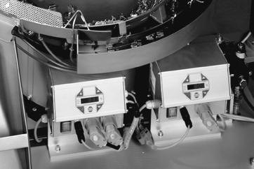
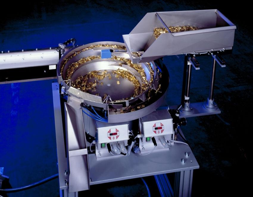
2 1.1 Functional description The modules dose the power at the vibrating magnets through phase angle without further control. The setting of power is done with a potentiometer, analogue reference 2 to 10 Volt DC or analogue constrainedcurrent operation 0 to 20 ma. The aforementioned reference value allows line lengths of more than 10 meters, o therwise the max length of the line is 3 m. When operating between heavy interference centres, the control wires should be shielded. The output voltage for the smallest reference values 0 Volt (potentiometer at the left catch) can be selected with the trimming potentiometer between 0 and 90 Volt (eff.) The highest output voltage at the reference vale 100 % can be set with the trimming potentiometer U max between 150 and 220 Volteff. An enable input allows the module to be switched on and off wattless. Enable can be done with a normally open contact or voltage signal Volt DC. The connections for the reference value and enable are free from the mains potential. Pins 19 and 20 are made available for the operating mode. If these pins are bridged, the module is working on symmetric full wave. The vibration is then working with double the mains frequency. A missing connection leads to an asymmetric half wave, so that the vibrating drive is working on the mains frequency. The fuses are accessible from the front panel. It is a microfuse 5x20 mm. The value for the module ESM 906 is 10 A super quick. This fuse is only to protect the internal semiconductor. An overload fuse to protect the complete unit has to be done external (i=6a). The module ESM 910 has now own fuse, but it has a shortcircuitproof on the main power supply unit. The modules are provided with a fixed preset soft start. Setup The modules have, at the left side wall, a heat dissipation plate for the power semiconducter. Therefore it is necessary to have a free space of a least 50 mm to the next appliance for heat dissipation. 1.2 EC Conformity/CSA Conformity The control unit complies with the following regulations: EC EMC Directive 89/336/EEC EC Low voltage equipment directive (73/23/EEC) Applied harmonised standards: EN T.1 EC EMC Directive EN EN 50011, Limit value class B EC EMC Directive EN Applied national technical specifications: BGV A2 1 Types et charactéristiques Type Mains Voltage and power RNA item no. ESM V 6% 10%; 50/60 Hz; max 6 A load current ESM V 6% 10%; 50/60 Hz; max 6 A load current ESM V 6% 10%; 50/60 Hz; max 10 A load current ESM V 6% 10%; 50/60 Hz; max 10 A load current Type ESM 906 ESM 910 Load voltage V ( V) Output current A A Set value Potentiometer 10 k>; V DC or ma DC Enable input Potential free contact / V DC, Ri 10 k> Ambient temperature C Protection IP 20 Applied standards EN ; EN ; VDE 0160; VBG 4

3 2 Safety Instructions It is always necessary to read and understand the safety instructions. This ensures that valuable material is not damaged and injuries are avoided. Steps must be taken to ensure that all persons working with this control unit are familiar with the safety regulations and observe them. The device described in this manual is a control unit for operating RNA bowl feeders and linear feeders. The limit values specified in the technical data must be observed. Note! This hand indicates tips on operation of the control unit. Attention! This warning triangle indicates safety instructions. Failure to heed this warning can lead to severe injuries or death! Work on electrical equipment of the machine/plant may be carried out only by a trained electrician or by untrained persons under the leadership and supervision of a trained electrician in accordance with the regulations for electrical engineering! 3 Commissioning Instructions Before connecting up to the mains and switching on the control unit, it is essential to check the following points: Is the control unit in proper working condition and closed with all screws? Are the connector locks clicked in/screwed secure? Are all cables and glands intact? Is PROPER INTENDED USAGE ensured? Does the mains voltage specification on the control unit agree with the local mains voltage? Does the mains frequency specification on the vibratory drive agree with the local mains? Is the correct operating mode set on the control unit? (See "Operating Mode" section) Operation of the control unit may be commenced only when all questions asked above can be answered unambiguously with YES. Before you start operation after repair work has been carried out or control units/vibrating drives have been exchanged, set the output on the control unit to minimum before switching on. Check that the system is working properly when you increase the output. All safety and danger signs on the machine/plant must be observed! The electrical equipment of a machine/plant must be inspected and checked regularly. Defects such as loose connections or damaged cables must be remedied immediately! Before commencing operation, make sure that the earthing line (power earth, PE) is intact and installed at the connecting point. Only test instruments approved for this purpose may be used for checking the safety grounding conductor.
4 6 Schéma électrique mains supply PE N L Connecting diagram mode indicatio enable 2 bridge F1 ESM 906 / ESM 910 PE mode enable 1 reference value Y1 linear feeder bowl feeder max. 6 A (ESM 906) max. 10 A (ESM 910) fuse F1 only for ESM /120 Hz /60 Hz contact 9 10 signal V DC bridge at reference by current loop potentiometer 10 kohm variable voltage source Volt DC variable current loop ma DC Note: The connecting diagram for the Modul ESM910 is identical. Only the two statusoutputs on clamp 1 upto 4 are not available. Here the clamp 1 and 2 have to bridge. 5 Plan dimensionnel 111,6 103,8 label of type ESM 906 Us Umax Umin , label of type UB Umax Umin ESM
 02351/41744 Fax (49) 02351/45582 RheinNadel Automation GmbH Zweigbetrieb Ergolding Ahornstraße")
5 RheinNadel Automation GmbH Reichsweg 19/42 D Aachen Tel (49) 0241/ Fax (49) 0241/ Internet vertrieb@rna.de RheinNadel Automation GmbH Zweigbetrieb Lüdenscheid Nottebohmstraße 57 D Lüdenscheid Tel (49) 02351/41744 Fax (49) 02351/45582 RheinNadel Automation GmbH Zweigbetrieb Ergolding Ahornstraße 122 D Ergolding Tel (49) 0871/72812 Fax (49) 0871/77131 HSH Handling Systems Wangenstr. 96 CH 3360 Herzogenbuchsee Tel (41) 062/ Fax (41) 062/ Internet info@handlingsystems.ch Verkaufsbüro Kurt Allemann, Dahlienstrasse 9, CH4533 Riedholz Telefon (0 32) Telefax (0 32) RNA AUTOMATION LTD Hayward Industrial Park Tameside Drive, Castle Bromwich GB Birmingham, B 35 7 AG Tel (44) 0121/ Fax (44) 0121/ Internet rna@rnauk.com Vibrant S.A. Pol. Ind. Famades C/Energia Parc 27 E Cornelia Llobregat (Barcelona) Tel (34) 09/ Fax (34) 093/ Internet info@vibrantrna.com RNA Automated Systems Inc. P.O.Box 560, Paris, Ontario, Canada, N3L 3T6 Tel (1) 519/ Fax (1) 519/ sales@rnacan.com VTBAESM910GB Stand:
Operating instructions Control units for oscillating drives
 Operating instructions Control units for oscillating drives ESG 1000 BA Rhein-Nadel Automation GmbH Rhein - Nadel Automation GmbH 1 19.09.2012 Table of contents Chapt... Page 1 Technical data 3 2 Safety
Operating instructions Control units for oscillating drives ESG 1000
 Operating instructions Control units for oscillating drives ESG 1000 BA Rhein-Nadel Automation GmbH Table of contents Chapt... Page 1 Technical data 1.1 Functional description... 3 1.2 EG - conformity...
Figure 1: Device components
 Order No. : 2860 10 Order No. : 2830 10 Operation- and Assembly Instructions 1 Safety instructions Electrical equipment may only be installed and fitted by electrically skilled persons. Failure to observe
NetterVibrotron SRF. Operating Instructions for. Series SRF. These operating instructions apply to. Netter Static Adjustable Frequency Control
 Operating Instructions for Netter Static Adjustable Frequency Control Series SRF July 2016 No.1451E Page 1/23 These operating instructions apply to Netter Static Adjustable Frequency Control NetterVibrotron
Inductive sensor With analog output BI15-M30-LI-EXI
 ATEX category II 1 G, Ex-zone 0 ATEX category II 2 D, Ex-zone 21 Threaded barrel, M30 x 1.5 Chrome-plated brass 2-wire, 14 30 VDC Analog output 4 20 ma Cable connection Wiring Diagram Type designation
Operating Instructions 07/2007 Edition. SINAMICS G130/G150 Line harmonics filter. sinamics
 Operating Instructions 07/2007 Edition SINAMICS G130/G150 Line harmonics filter sinamics s Safety information 1 General 2 SINAMICS SINAMICS G130/G150 Operating Instructions Mechanical installation 3 Electrical
3 Cleaning. 4 Technical data
 EXC+ EXC- Sig- SIG+ SEN- SEN+ 2.4 Attaching cable to the analog board Attaching cable of the weighing cell to the system solution Connect the cable to the appropriate terminal strip of the Ex1 system solution
Sentronic PLUS. Electronic Pressure Regulator. Installation Manual
 Sentronic PLUS Electronic Pressure Regulator Electronic Pressure Regulator Sentronic PLUS Sentronic PLUS Electronic Pressure Regulator General Electrical Characteristics Nominal Diameter DN (mm) Voltage
Inductive sensor. 2-wire, analog output BI8-M18-LI-EXI
 ATEX category II 1 G, Ex-zone 0 ATEX category II 2 D, Ex-zone 21 Threaded barrel, M18 x 1 Chrome-plated brass 2-wire, 14 30 VDC Analog output 4 20 ma Cable connection Wiring diagram Type code Ident no.
SINAMICS G130 / G150. Line harmonics filter. Operating Instructions 05/2010 SINAMICS
 SINAMICS G130 / G150 Line harmonics filter Operating Instructions 05/2010 SINAMICS s Safety information 1 General 2 SINAMICS SINAMICS G130 / G150 Operating Instructions Mechanical installation 3 Electrical
DMP 339. Pressure Transmitter. with G ¼" flush diaphragm. Pressure Transmitter. Industrial. accuracy according to IEC 60770: 0.
 DMP 9 Industrial Pressure Transmitter with G ¼" flush diaphragm accuracy according to IEC 60770: 0.5 % FSO Industrial Pressure Transmitter DMP 9 Nominal pressure from 0... 60 bar up to 0... 600 bar Output
MICROMASTER Encoder Module
 MICROMASTER Encoder Module Operating Instructions Issue 01/02 User Documentation Foreword Issue 01/02 1 Foreword Qualified Personnel For the purpose of this Instruction Manual and product labels, a Qualified
Sentronic PLUS Electronic Pressure Regulator. Installation Manual
 Sentronic PLUS Electronic Pressure Regulator Installation Manual Sentronic PLUS ASCO NUMATICS Sentronic PLUS Electronic Pressure Regulator Electrical Characteristics * Max. ripple: 10 % Specifications
Operating Manual (Edition 04/2004) sinamics. Line Reactors SINAMICS G130
 sinamics. Line Reactors SINAMICS G130") Operating Manual (Edition 04/2004) sinamics Line Reactors SINAMICS G130 Contents 1. Safety Information 2 2. General 5 3. Mechanical Installation 6 4. Electrical Installation 8 5. Technical Specifications
Operating Manual (Edition 04/2004) sinamics Line Reactors SINAMICS G130 Contents 1. Safety Information 2 2. General 5 3. Mechanical Installation 6 4. Electrical Installation 8 5. Technical Specifications
INSTRUCTION MANUAL. Controller CLT-500 / RG-500
 INSTRUCTION MANUAL Date of issue: July 2007 Version: V1.09 Controller CLT-500 / RG-500 working place controller for electric screwdrivers High - System - Technik Index 1. Priciple information... Seite
Dimensions. Model Number. Electrical connection. Features. Pinout Product information. Indicators/operating means. LGS25 Serie.
 Q Dimensions Transmitter Detection field + 9. Detection field 7.8 n Beam. Beam Receiver III 0. 0 Fix H H H Fn Model Number Light grid with fixed cable with -pin, M x connector, and fixed cable with 8-pin,
Kuhnke Technical Data. Contact Details
 Kuhnke Technical Data The following page(s) are extracted from multi-page Kuhnke product catalogues or CDROMs and any page number shown is relevant to the original document. The PDF sheets here may have
(1) (2) (3) Bedienungs- und Montageanleitung. Safety instructions. Structure of the device
 (2) (3) Bedienungs- und Montageanleitung. Safety instructions. Structure of the device") 3 x cinch/s-video socket Order no. 33 1532 xx USB/3.5 mm audio socket Order no. 33 1539 xx VGA socket Order no. 33 1540 xx VGA socket with screw-in lift terminals Order no. 33 1541 xx High definition socket
3 x cinch/s-video socket Order no. 33 1532 xx USB/3.5 mm audio socket Order no. 33 1539 xx VGA socket Order no. 33 1540 xx VGA socket with screw-in lift terminals Order no. 33 1541 xx High definition socket
Operating Instructions Dimmer for V Incandescent Lamps
 Operating Instructions Incandescent Lamps 1. Safety instructions Attention: Electrical equipment must be installed and fitted only by qualified electricians and in observance of the current accident prevention
Contactless encoder RI360P0-QR24M0-INCRX2-H1181
 Compact, rugged housing Many mounting possibilities Status displayed via LED LED indicates measuring range Immune to electromagnetic interference 1024 pulses per revolution (default) 360, 512, 1000, 1024,
Operating instructions
 108183 2017-05-17 Page 1 0359 Operating instructions TPPL-EX series Hazardous environments luminaires Please read the instructions carefully before starting any works! Content: 1. Safety instructions 2.
AMU2-2MHD+ Audio monitoring Unit
 AMU2-2MHD+ Audio monitoring Unit Handbook TSL Vanwall Road, Maidenhead, Berkshire, SL6 4UB Telephone +44 (0)1628 676200, FAX +44 (0)1628 676299 AMU2-2MHD+-6 1 ISSUE 5 SAFETY Installation. Unless otherwise
Guide for installers. METTLER TOLEDO MultiRange System solution analog Ex1. Hazardous area. Safe area
 Guide for installers METTLER TOLEDO MultiRange System solution analog Ex1 Hazardous area Safe area System solution analog Ex1 Contents Contents Page 1 Safety precautions... 2 2 System overview... 3 2.1
OM2000N INSTALLATION MANUAL
 OM2000N INSTALLATION MANUAL 2 1 Figure A 1 2 Laser Beam Output Window Power Cable 821001342 (Rev. B) DESCRIPTION The OM2000N oscillating mirror is an accessory for the 2000N family laser scanners: DS2100N,
EA63-7D. Generator Automatic Voltage Regulator Operation Manual. Self Excited Automatic Voltage Regulator
 EA63-7D Generator Automatic Voltage Regulator Operation Manual Self Excited Automatic Voltage Regulator SP POWERWORLD LTD Willows, Waterside, Ryhall, Stamford, Lincs, PE9 4EY, UK Tel: +44 1780 756872 -
Inductive sensor NI3-EG08K-Y1-H1341
 ATEX category II 1 G, Ex zone 0 ATEX category II 1 D, Ex zone 20 SIL2 (Low Demand Mode) acc. to IEC 61508, PL c acc. to ISO 13849-1 at HFT0 SIL3 (All Demand Mode) acc. to IEC 61508, PL e acc. to ISO 13849-1
Achat 115 Sub A active subwoofer. user manual
 Achat 115 Sub A active subwoofer user manual Musikhaus Thomann Thomann GmbH Hans-Thomann-Straße 1 96138 Burgebrach Deutschland Telephone: +49 (0) 9546 9223-0 E-mail: info@thomann.de Internet: www.thomann.de
Gamma instabus. Technical product information
 Gamma instabus Technical product information Universal dimmer N 554D31, 4 x 300 VA / 1x 1000 VA, AC 230 V Universal dimmer N 554D31 Control of dimmable lamps, including LED without minimum load Output
Contactless Encoder Incremental: ppr RI360P0-QR24M0- INCRX2-H1181
 Compact, rugged housing Many mounting possibilities Status displayed via LED Immune to electromagnetic interference 1024 pulses per revolution (default) 360, 512, 1000, 1024, 2048, 2500, 3600, 4096, parametr.
DMP 331 DMP 331. Industrial Pressure Transmitter. for Low Pressure. Stainless Steel Sensor. Pressure Transmitter. Industrial. tri-matic.
 DMP Industrial Pressure Transmitter for Low Pressure Stainless Steel Sensor accuracy according to IEC 60770: standard: 0.5 % FSO option: 0.5 / 0. % FSO Industrial Pressure Transmitter from 0... 00 mbar
Contactless Encoder Analog RI360P0-QR24M0-ELIU5X2-H1151
 Compact, rugged housing Many mounting possibilities Status displayed via LED Measuring range indicated via LED Immune to electromagnetic interference Measuring range programmable via Easy Teach Output
Guide for installers. METTLER TOLEDO MultiRange System solution Point Ex.
 Guide for installers METTLER TOLEDO MultiRange System solution Point Ex www.mt.com/support System solution Point Ex Contents Contents Page 1 Safety precautions... 4 2 System overview... 5 2.1 Using the
G.R.A.S. Sound & Vibration
 Instruction Manual Single-channel Low-noise Measuring System consisting of: ½-inch Low-noise Level Microphone System Type 40HH and Power Module Type 12HF 40HH 12HF G.R.A.S. Sound & Vibration Skovlytoften
Inductive sensor NI10-M18-Y1X-H1141
 ATEX category II 1 G, Ex zone 0 ATEX category II 1 D, Ex zone 20 SIL2 (Low Demand Mode) acc. to IEC 61508, PL c acc. to ISO 13849-1 at HFT0 SIL3 (All Demand Mode) acc. to IEC 61508, PL e acc. to ISO 13849-1
Magnetic field sensor for pneumatic cylinders BIM-IKT-Y1X
 ATEX category II 2 G, Ex zone 1 ATEX category II 1 D, Ex zone 20 SIL2 as per IEC 61508 Rectangular, height 17 mm Metal, GD-Zn Magnetic-inductive sensor DC 2-wire, nom. 8.2 VDC Output acc. to DIN EN 60947-5-6
Self Excited Automatic Voltage Regulator For Generator Compatible with Marathon SE350* Operation Manual
 Self Excited Automatic Voltage Regulator For Generator Compatible with Marathon SE350* Operation Manual s * Use for reference purpose only and not a genuine Marathon product. 1. INTRODUCTION Sensing Input
Contactless Encoder IO-Link Ri360P0-QR24M0-IOLX2-H1141
 Compact, rugged housing Many mounting possibilities Status displayed via LED Immune to electromagnetic interference 16 bits singleturn Process value in 32 bit telegram 3 error bits 16 bits singleturn 15
Process transmitter RMA422
 Technical information TI072R/09/en Mat. No. 51001905 Process transmitter RMA422 Multifunctional 1-2 channel top hat DIN rail unit with intrinsically safe current input and loop power supply, alarm set
INSTALLATION AND OPERATING MANUAL FOR ALL MATSUKO SWITCHBOX MODELS SWB 5 SWB 5P SWB 5P+PG WARNING:
 MSB12906121MAN UK English INSTALLATION AND OPERATING MANUAL FOR ALL MATSUKO SWITCHBOX MODELS SWB 5 SWB 5P SWB 5P+PG WARNING: Ensure that the Matsuko Switchbox is switched off at the mains before you attempt
Inductive sensor BI1.5-EG08K-Y1
 ATEX category II 1 G, Ex zone 0 ATEX category II 1 D, Ex zone 20 SIL2 (Low Demand Mode) acc. to IEC 61508, PL c acc. to ISO 13849-1 at HFT0 SIL3 (All Demand Mode) acc. to IEC 61508, PL e acc. to ISO 13849-1
EA350. Generator Automatic Voltage Regulator Operation Manual
 Generator Automatic Voltage Regulator Operation Manual Self Excited Automatic Voltage Regulator For General Generators Compatible with Marathon SE350* * Use for reference purpose only and not a genuine
KHT 1000C HV-Probe Calibrator. Instruction Manual
 KHT 1000C HV-Probe Calibrator Instruction Manual Copyright 2015 PMK GmbH All rights reserved. Information in this publication supersedes that in all previously published material. Specifications are subject
TECHNICAL MANUAL DRAW-WIRE DISPLACEMENT TRANSDUCER TYPE DWT
 RDP Customer Document TECHNICAL MANUAL DRAW-WIRE DISPLACEMENT TRANSDUCER TYPE DWT Doc. Ref CD1004L BS EN ISO 9001 Certificate No. FM13141 Affirmed by Declaration of Conformity USA & Canada RDP Electrosense
KRF EMC Filters Installation, Operation and Maintenance Manual
 KRF EMC Filters Installation, Operation and Maintenance Manual KRF EMC Filters limit high frequency noise, as well as: Reduce interference Protect sensitive equipment Eliminate drive cross-talk Meet FCC
Instruction Manual. Universal Flow Controller Model 261 / 261-EC-01
 Universal Flow Controller Model 261 / 261-EC-01 Instruction Manual Type ARS 261-EC 01 Art.-no: 82212264 Table of Contents 1. Safety Instructions 2. Product ID - Dimensions 3. Function Description 4. Installation
9I273 01/10/2012 COU-03/0 AUTOMATIC CHANGEOVER UNIT TO BACK-UP AMPLIFIER
 9I273 01/10/2012 COU-03/0 1 CONTENTS 1. SPECIFICATIONS... 3 2. BLOCKS DIAGRAM... 3 3. FRONT VIEW... 4 4. REAR VIEW... 4 5. CONTROL MODULE... 4 6. ZONE CARD (COU-03FC or COU-03EC)... 6 6.1. Diagram... 6
PNP300 & PNP350 POP N PLUG SLIM INTERCONNECT BOX USER S GUIDE
 The is shown above. MANUAL PART NUMBER: 400-0114-004 & PNP350 POP N PLUG SLIM INTERCONNECT BOX USER S GUIDE TABLE OF CONTENTS Page PRECAUTIONS / SAFETY WARNINGS... 2 GENERAL...2 HANDLING...2 CLEANING...2
ELECTRICAL. DATA AND INDEX Not all complements shown A shown for reference. Index A leads B, CW (from shaft end) TERMINAL CONNECTIONS COM VCC CASE
 TERMINAL CONNECTIONS COM VCC CASE") NorthStar brand SERIES HD35R Heavy Duty Encoder Key Features Phased Array Sensor for Reliable Signal Output Rugged Design with Wide-Spaced Oversized Bearings Unbreakable Code Disc up to 5000PPR Improved
NorthStar brand SERIES HD35R Heavy Duty Encoder Key Features Phased Array Sensor for Reliable Signal Output Rugged Design with Wide-Spaced Oversized Bearings Unbreakable Code Disc up to 5000PPR Improved
ABB i-bus EIB Universal dimmer 6155 EB for Installation
 73-1 - 5975 23459 ABB i-bus EIB Universal dimmer 6155 EB - 101-500 for Installation Operating instructions only for authorized, skilled electricians with EIB training Important instructions Attention It
120cm (4x36 Watt) incl. Splitter Instruction Manual
 incl. Splitter Instruction Manual") 120cm incl. Splitter Instruction Manual Table of contents 1 Description of Device and Functions... 3 1.1 Safety Instructions... 4 2 Preparation and Installation... 5 2.1 Mounting... 5 2.2 Secure the...
120cm incl. Splitter Instruction Manual Table of contents 1 Description of Device and Functions... 3 1.1 Safety Instructions... 4 2 Preparation and Installation... 5 2.1 Mounting... 5 2.2 Secure the...
TeSys contactors. Model d. Type of contactor LC1- LC1- LC1- LC1- LC1-D115 & D09 D18 D25 D38 D40 D50 D95 LC1-D150 DT20 & DT25 DT32 & DT40
 Characteristics Type of contactor LC- LC- LC- LC- LC-D & D09 D8 D2 D38 D40 D0 D9 LC-D0 DT20 & DT2 DT32 & DT40 Environment Rated insulation voltage (Ui) Conforming to IEC 947-4-, overvoltage category III,
4 Wiring Brochure Wiring and installation of specific control
 - Wiring Brochure tekmarnet 4 User Switch 480 W 480 09/09 1 Information Brochure Choose controls to match application 2 Application Brochure Design your mechanical applications 3 Rough In Wiring Rough-in
DSP 18 Sub active subwoofer. user manual
 DSP 18 Sub active subwoofer user manual Musikhaus Thomann Thomann GmbH Hans-Thomann-Straße 1 96138 Burgebrach Germany Telephone: +49 (0) 9546 9223-0 E-mail: info@thomann.de Internet: www.thomann.de 05.11.2018,
PicoScope 2000 Series PC Oscilloscopes
 PicoScope 2000 Series PC Oscilloscopes User guide I PicoScope 2000 Series User Guide Table of Contents 1 Introduction...2...2 1 Overview...2 2 Safety symbols...3 3 Safety warning...3 4 FCC notice 5 CE
User Manual CC DC 24 V 5A. Universal Control Unit UC-1-E. General Information SET. Universal Control Unit UC-1 Of Central Lubrication PAUSE CONTACT
 Universal Control Unit UC-1-E User Manual General Information Universal Control Unit UC-1 Of Central Lubrication CC DC 24 V 5A / M 15 SL /MK 31 M Z 30 General Information Contents Universal Control Unit
Installation Manual IPT Installation of skillet systems with 125 A track current. MV a-E.
 www.wampfler.com Page 1 of 27 Index Page 1 Basics...4 2 Basic understanding of an IPT -system...5 3 General rules regarding metal parts in close proximity...6 3.1 Envelope free of ferromagnetic material...6
Actuators IC 20, IC 40
 Actuators IC 20, IC 40 IC 20 for basic applications with three-point step control and automatic/manual mode changeover for easy commissioning IC 40 for complex applications with programmable functions
Recording to Tape (Analogue or Digital)...10
...10") c o n t e n t s DUAL MIC-PRE Green Dual Mic Pre (introduction).............................4 Section (i): Setting Up Power Connections...........................................4 Power Supply................................................5
c o n t e n t s DUAL MIC-PRE Green Dual Mic Pre (introduction).............................4 Section (i): Setting Up Power Connections...........................................4 Power Supply................................................5
GV 460 / GV 461 Impulse Splitters for Incremental Encoders with Potential Separation between Input and Outputs
 control motion interface GV 460 / GV 461 Impulse Splitters for Incremental Encoders with Potential Separation between Input and Outputs GV 480 / GV 481 Impulse Splitters for Incremental Encoders with all-around
Contactless encoder Ri360P0-QR24M0-HESG25X3-H1181
 Compact, rugged housing Many mounting possibilities Status displayed via LED Positioning element and aluminium ring not incl. SSI output 25 bit, Gray-coded SSI clock rate: 62.5 KHz 1 MHz Single or multiturn,
PicoScope 3000 Series Automotive User guide
 PicoScope 3000 Series Automotive User guide PS3000A044 v1.0 I PicoScope 3000 Series Automotive PC Oscilloscopes Table of Contents 1 Introduction...2...2 1 Overview...2 2 Minimum PC requirements...2 3 Installation
ACCESSORIES MANUAL PART NUMBER: PRODUCT REVISION: 1 PNP202. Interconnect Box USER'S GUIDE
 MANUAL PART NUMBER: 400-0109-001 PRODUCT REVISION: 1 PNP202 Interconnect Box USER'S GUIDE INTRODUCTION Your purchase of the PNP202 Interconnect Box is greatly appreciated. We are sure you will find it
Tube Rotator. User Guide. Version 1.2
 Tube Rotator User Guide Version 1.2 Figure 1: Fixed Speed Model Tube holder spindle Tilt adjustment wheel IEC power inlet socket (at rear) Power on/off switch Figure 2: Variable Speed Model Tube holder
Installation and User Guide 458/CTR8 8-Channel Ballast Controller Module
 Installation and User Guide 458/CTR8 8-Channel Ballast Controller Module Helvar Data is subject to change without notice. www.helvar.com i Contents Section Page Introduction 1 Installation 2 1. Attach
Magnetic Field Sensor for pneumatic cylinders BIM-IKT-Y1X
 ATEX category II 2 G, Ex zone 1 ATEX category II 1 D, Ex zone 20 SIL2 (Low Demand Mode) acc. to IEC 61508, PL c acc. to ISO 13849-1 at HFT0 SIL3 (All Demand Mode) acc. to IEC 61508, PL e acc. to ISO 13849-1
Sevenlogic Comfort Timer Switch
 Operating manual Sevenlogic Comfort Timer Switch RoHS compliant 2011/65/EU General safety instructions...1 Technical data & included with delivery...2 Electrical connection...2 Assembly...3 Setting inching
Industriefunkuhren. Technical Manual. IRIG-B Generator-Module for analogue / digital Signals of Type: IRIG-B / IEEE C / AFNOR NF S87-500
 Industriefunkuhren Technical Manual IRIG-B Generator-Module for analogue / digital Signals of Type: IRIG-B / IEEE C37.118 / AFNOR NF S87-500 Module 7628 ENGLISH Version: 02.01-06.03.2013 2 / 20 7628 IRIG-B
Series SM ø12 mm. Inductive Position Transducer. ranges mm. linearity 0,2/0,3% ø12 mm, clamp-ø8 mm h6. out: AC, V, V, 4...
 LVDT Inductive Position Transducer Series SM ø12 mm ranges 2...200 mm linearity 0,2/0,3% ø12 mm, clamp-ø8 mm h6 out: AC, 0...10 V, 0...5 V, 4...20 ma with external or integrated cable electronics repeatability
SquareLED - Aura Bar & Matrix Beam Light 100
 SquareLED - Aura Bar & Matrix Beam Light 100 1. SAFETY INSTRUCTIONS Please read these instructions carefully they include the important information about the installation usage and maintenance of this
DATA SHEET Panorama Rudder Indicator, TRI-2
 DATA SHEET Panorama Rudder Indicator, TRI-2 Class 1 accuracy on CAN version Readable from up to 5 metres Single and dual CAN or analogue interface LED illumination DEIF A/S Frisenborgvej 33 DK-7800 Skive
AMU1-BHD+ Audio monitoring Unit
 AMU1-BHD+ Audio monitoring Unit Handbook TSL Vanwall Road, Maidenhead, Berkshire, SL6 4UB Telephone +44 (0)1628 676200, FAX +44 (0)1628 676299 AMU1-BHD+-6 1 ISSUE 6 SAFETY Installation. Unless otherwise
ISP-W 350 till 1200 ISP-R 350 till 1200 ISP-B 350 till 1200 ISP-Motiv 450 till 950 with receiver RF Edition: 05/16 Nr
 Installation and technical manual ISP-W / R / B / motives frameless with receiver RF 2 3 ISP-W 350 till 1200 ISP-R 350 till 1200 ISP-B 350 till 1200 ISP-Motiv 450 till 950 with receiver RF Edition: 05/16
POWER SUPPLIES COAX DC INSERTERS SITUATION
 SITUATION devices require voltage on the coax output connector and RF signals must pass from input to output on the power inserter. SOLUTION Sonora power inserters couple regulated voltage on coax cables
Capacitive sensor BCT5-S18-UP6X2T-H1151
 M18 1 threaded barrel Plastic, PA12-GF30 Teach-in and configuration via buttons on the device, pin 5 and IO-Link Wiring Diagram Functional principle Type designation Ident no. 2101100 Remark to product
ROBOT INTERFACE LIGHT
 ROBOT INTERFACE LIGHT Instruction manual Arc detector kit Interface FUNCTIONS KIT number * Arc detect output Error input Trigger input (welding start) Current/wire speed control Voltage/Trim control Welding
Operating instructions Electronic preset counter Type series 717
 Operating instructions Electronic preset counter Type series 717 1. Description 5.98.3_gb 6-digit adding/subtracting counter with two presets Very bright 8mm high LED display Counting and preset range
DMP 335. Industrial Pressure Transmitter. Welded, Dry Stainless Steel Sensor. accuracy according to IEC 60770: 0.5 % FSO.
 DMP 5 Industrial Pressure Transmitter Welded, Dry Stainless Steel Sensor accuracy according to IEC 60770: 0.5 % FSO Nominal pressure from 0... 6 bar up to 0... 600 bar Output signals -wire: 4... 0 ma -wire:
SPECIAL SPECIFICATION 2344 TMC Support Equipment
 2004 Specifications CSJ 0912-00-488 SPECIAL SPECIFICATION 2344 TMC Support Equipment 1. Description. Furnish Traffic Management Center (TMC) support equipment in the City of Missouri City TMC location
TS2.8 Sub OWNER S MANUAL
 TS2.8 Sub OWNER S MANUAL TS2.8 Sub CONTENTS IMPORTANT SAFETY INSTRUCTIONS 03 WARNINGS 03 FUSE PROTECTION 04 WARNING: STRONG MAGNETIC FIELD 04 EMC / EMI 04 ECODESIGN STANDBY POWER CONSUMPTION 04 WARRANTY
Modular DAA with 2/4 Wire Convertor. XE0002D Block Diagram
 XE0002D August 2005 Modular DAA with 2/4 Wire Convertor Description The XE0002D is a compact DAA module designed for applications requiring voice, data or fax transfer. It complies with FCC Part 68 rules
MB 204/MB 204-Ex. Multi-Barrier for PROFIBUS PA and FOUNDATION Fieldbus 10/ EN
 Multi-Barrier for PROFIBUS PA and FOUNDAION Fieldbus 10/63-6.11 EN P R O F I PROCESS FIELD BUS B U S Intrinsically safe power supply of up to 31 stations on the bus, cascadable multi-barrier Intrinsically
CURRENT INJECTION RELAY TESTER CR-100. ( Code P60212 (770081) ) INSTRUCTIONS MANUAL ( M / 05A ) (c) CIRCUTOR S.A.
 ) INSTRUCTIONS MANUAL ( M / 05A ) (c) CIRCUTOR S.A.") CURRENT INJECTION RELAY TESTER CR-100 ( Code P60212 (770081) ) INSTRUCTIONS MANUAL ( M 981 329 / 05A ) (c) CIRCUTOR S.A. ---- CURRENT- TIME TRIP TESTER CR-100 --------------- Page. 2 CURRENT INJECTION
CURRENT INJECTION RELAY TESTER CR-100 ( Code P60212 (770081) ) INSTRUCTIONS MANUAL ( M 981 329 / 05A ) (c) CIRCUTOR S.A. ---- CURRENT- TIME TRIP TESTER CR-100 --------------- Page. 2 CURRENT INJECTION
TVAC20000 User manual
 TVAC20000 User manual Version 01/2010 Original English user manual. Keep for future use. 10 Introduction Dear Customer, Thank you for purchasing this product. This product meets the requirements of the
Linear flow control with actuator IFC
 Linear flow control with actuator Product brochure GB 3 Edition 01.14 Linear relationship between adjustment angle and flow rate Large control ratio of 25:1 EC type-tested and certified Actuators IC 20
Model P/03P Upconverters
 Instruction Manual Model 2005-02P/03P Upconverters October 2013, Rev H 2005 TEST UPCONVERTER GHz 100MHz10MHz 1MHz C KU 70 140 IF IN GAIN DC POWER +DC IN +15V, 200 ma RF OUT DC ALARM LO IF FREQUENCY J1
DMP 343. Industrial Pressure Transmitter. Without Media Isolation. accuracy according to IEC 60770: 0,35 % FSO. Nominal pressure
 DMP 4 Industrial Pressure Transmitter Without Media Isolation accuracy according to IEC 60770: 0,5 % FSO Nominal pressure from 0... 0 mbar up to 0... 000 mbar Product characteristics excellent linearity
TRF STEP-DOWN TRANSFORMER USER MANUAL
 TRF STEP-DOWN TRANSFORMER USER MANUA www.ventilation-system.com 2013 ! WARNING The present operation manual consisting of the technical details, operating instructions and technical specification applies
LED MODULES READYLINE DL
 LED MODULES READYLINE DL BUILT-IN MODULE LED-MODULE READYLINE DOWNLIGHT DL WU-M-538 / WU-M-539 / WU-M-540 Typical Applications Downlights Replacement for CFL DIRECT MAINS CONNECTION REDUCED FLICKER HIGH
ART2000i Digital Dimming System. Installation guide. Stock number *8200-
 ART2000i Digital Dimming System Installation guide Stock number 8200-0159 *8200- 0159* Useful Avolites phone numbers:- Avolites England Sales and service* (+44) (0) 20 8965 8522 Service out of hours* (+44)
BP2-MM MM Phono Preamplifier Owner s Manual
 BP2-MM MM Phono Preamplifier Owner s Manual Important Safety Instructions The lightning flash with arrowhead symbol within an equilateral triangle, is intended to alert the user to the presence of un-insulated
LVDT. Inductive Position Transducer - Hydraulic Series. SM-HYD Hydraulic Series. Key-Features:
 HM 1808 LVDT Inductive Position Transducer - Hydraulic Series SM-HYD Hydraulic Series Key-Features: Content: - Screw flange M18x1,5 / M30x1,5 or plug-in flange Ø18 - Pressure up to 400 bar - Measurement
Electronic MICROSTAT-T Temperature controller with digital indication for use with resistance thermometers and thermocouples Series 8650
 M. K. JUCHHEIM GmbH & Co Delivery address:mackenrodtstraße 14, 36039 Fulda, Germany Postal address: 36035 Fulda, Germany Phone: +49 661 6003-0 Fax: +49 661 6003-607 E-mail: mail@jumo.net Internet: www.jumo.de
1 Safety instructions. 2 Device components. 3 Function. Light Management Relay switch insert 2-channel. Art.-No.: 1202 URE.
 Art.-No.: 1202 URE Operationsmanual 1 Safety instructions Electrical equipment may only be installed and fitted by electrically skilled persons. Failure to observe the instructions may cause damage to
Documentation. Magnetic Encoder System (MES) Version: Date:
 Version: Date:") Documentation Magnetic Encoder System (MES) Version: Date: 1.1 2016-02-26 Table of content Table of content 1 Foreword... 4 1.1 Notes on the documentation... 4 1.2 Intended use... 5 1.3 Documentation
Documentation Magnetic Encoder System (MES) Version: Date: 1.1 2016-02-26 Table of content Table of content 1 Foreword... 4 1.1 Notes on the documentation... 4 1.2 Intended use... 5 1.3 Documentation
STC-TC152USB-AT/AS/BTC/BSC STC-TB152USB-AT/AS/BTC/BSC Product Specification. Software Trigger USB 2.0 Color / Monochrome SXGA CCD Camera
 STC-TB152USB-AT/AS/BTC/BSC Product Specification Software Trigger USB 2.0 Color / Monochrome SXGA CCD Camera Safety Precautions CAUTION CAUTION RISK OF RISK ELECTRIC OF ELECTRIC SHOCK SHOCK DO NOT DO OPEN
SITRANS F flowmeters SITRANS F M. Transmitter MAG 6000 I/6000 I Ex d e 4/43
 Overview The MAG 6000 I/I Ex d transmitter is designed for the demands in the process industry. The robust die cast aluminium housing provides superb protection, even in the most harsh industrial environments.
HD-CM HORIZON DIGITAL CABLE METER
 HD-CM OFF! Max RF i/p = +17dBm 75Ω Max AC/DC i/p = 120Vrms MENU INPUT ON HORIZON DIGITAL CABLE METER Horizon Global Electronics Ltd. Unit 3, West Side Flex Meadow Harlow, Essex CM19 5SR Phone: +44(0) 1279
PH-1. Italian MM & MC Phono Preamplifier OWNER S MANUAL
 PH-1 Italian MM & MC Phono Preamplifier OWNER S MANUAL IMPORTANT SAFETY INFORMATION CAUTION: TO REDUCE THE RISK OF ELECTRIC SHOCK, DO NOT REMOVE COVER (OR BACK). NO USER-SERVICEABLE PARTS INSIDE. REFER
ACCESSORIES MANUAL PART NUMBER: TNP500. Universal Tilt N Plug Interconnect Box USER'S GUIDE
 MANUAL PART NUMBER: 400-0091-003 TNP500 Universal Tilt N Plug Interconnect Box USER'S GUIDE INTRODUCTION Your purchase of the TNP100 Tilt N Plug Interconnect Box is greatly appreciated. We are sure you
EMC Solutions Noise filtering
 Power & Signal Quality TRABTECH EMC Solutions Noise filtering Interference-free power supply and signal transmission A permanent supply and safe data link are essential for the operational reliability