MANUAL REFRACTOR. Special Attention
|
|
|
- Roderick Grant
- 5 years ago
- Views:
Transcription


1 - 1 -
2 MANUAL REFRACTOR Thank you for your taking MANUAL REFRACTOR this time. This MANUAL REFRACTOR is compactly designed to make accurate measurements of complicated Visual functions. You are required to read this manual carefully in order to become familiar with features and structures of this instrument.. Special Attention.This is a precision instrument and should be handled carefully..the plastic dust cover should be used whenever the instrument is not use..the instrument should not be used or left in a hot and humid or dusty place..do not break up the instrument as sufficient optical adjustments have been made o it at factory..remove dust off the lens with an air brush. If the lens should have been smeared with Fingerprints, wipe it clean with a fresh cloth softly..we would recommend you to have the lenses cleaned by a specialist yearly
3 Table of Contents ⒈ Standard equipment.2 ⒉ Subjective eye tester.3 ⒊ Nomenclature...4 ⒋ Detail of auxiliary lenses..5 ⒌ Measuring performance 5 ⒍ Preparation before eye testing..6 ⒎ Measuring myopia and astigmatism.7 ⒏ Precision measurements of astigmatic axis..8 ⒐ Precision measurements of astigmatic power 8 ⒑ Precision measurements of spherical power..9 ⒒ Eye balance test..9 ⒓ Measuring presbyopia.10 ⒔ Measuring heterophoria(horizontal)..10 ⒕ Measuring heterophoria(vertical) 11 ⒖ Details of rotating near point chart.11,12 ⒗ Distance compensation table 13,14 ⒘ Main specifications
4 ⒈Standard equipment 1. Near point scale ( 1 pce) 2. Main instrument(1 set) 3. Fitting screw (1 pce) 4. Near point chart holder ( 1 pce) C auxiliary lenses (2 pcs) C auxiliary lenses (2 pcs) 7. Accessory case (1 pce) 8. Silicon cloth (1 pce) 9. Rotating near point chart (1 pce) 10. Dust cover (1 pce) 11. Air brush (1 pce) 12. Lens cleaning fluid (I pce) 13. Glasses cloth 14. Instruction manual *The polystyrene case should be retained for use when sending the instrument back to the distributor or manufacturer for overhauled
5 ⒉ Subjective Eye Tester A New leveling mechanism B Fingertip adjustment for sphere power control Just the right figure from 0 to D and 0 to D obtained with light, fingertip control of the fast feed dial. Optional ±10.00D lenses are available. C Measuring astigmatism Readings 0 to -6.00D, which become possible up to -8.00Dwith accessory lenses -2.00D, Used in combination with the cross cylinder for precision measurement. D Cross cylinder (±0.25D) Tests are speeded up by eliminating the need for axis adjustment, a very efficient Synchronizing mechanism being provided and the loupe is readily turned by means of the knob. E Rotary prism The wider 1 D spacing the 20 D range simplifies reading and incorporation into the main body of the instrument means that a maximum field of view is obtained. F Unique new convergence system mechanism Convergence lever control for precision near point readings. G Wide range of auxiliary lenses combinations (See details on the page 6) H Precision Machined to finest tolerances The use of top quality bearings and elimination of the need for periodic lubrication 5

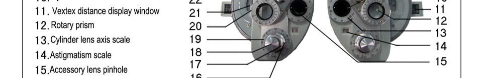

6 ⒊ Nomenclature 6

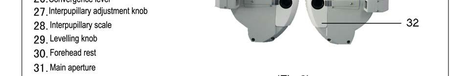
7 ⒋ Details of Auxiliary Lenses 12 Kinds of auxiliary lenses can be set at each main aperture on right and left sides. (fig.3) O Open aperture OC...Occluder ±0.50 ±0.50 cross cylinder 6 U 6 prism diopter base Up 10 I 10 prism diopter base In PH..Pinhole D auxiliary lens PL Red filter GL.Green filter RMH Red maddox rod, horizontal WMH White maddox rod,vertical RMV..Red maddox rod,vetical WMV.White maddox rod, vertical P135 Polarzing filter, axis 135 P45...Polarizing filter, axis 45 R.Retinoscopic lens, +2.00D (for 50 cm) ⒌ Measuring performance (A)Provides highly accurate readings over a wide range. Used in measurements of Myopia,Astigmatism,Hyperopia,Presbyopia.Hrterophoria,Range of Accommodation, Convergence, Aniseiconia,Stereopsis and Binocular Vision. (B) Rapid, accurate readings on binocular visual balance. (C) Speedy astigmatism tests With interlocking mechanism of the cross cylinder lens axis and the cylinder lens axis control ring, 7
 In short, middle and long distance test, it is possible to have the")
 Have the examinee sit on an eye")
 Adjust both readings the sphere power reading window (11) and")
 (C) Adjust the interpupillary scale (7) setting to the interpupillary")
 (D) Level the instrument with the leveling knob (3) while watching")
 (E) Align the examinee`s eyes with the righ and left main apertures")
 Turn the forehead rest adjusting knob(8) until the scale O on the")
8 one touch accurate astigmatism readings are now possible. (D) In short, middle and long distance test, it is possible to have the optical axis of the lens and the line of examinees`s vision coincide. ⒍ Preparation before Eye Testing (A) Have the examinee sit on an eye examination chair. (B) Adjust both readings the sphere power reading window (11) and astigmatism scale (19) to 0.00 ( Fi9. 4) (C) Adjust the interpupillary scale (7) setting to the interpupillary distance of the examinee.(fig.5) (D) Level the instrument with the leveling knob (3) while watching the level (6).( Fig.6) (E) Align the examinee`s eyes with the righ and left main apertures (28) and tighten the arm fixing knob. (F) Turn the forehead rest adjusting knob(8) until the scale O on the corneal backsight(26),, the corneal foresight(25) and the vertex of the cornea of the examinee are all in a straight line.(fig.7) (Fig.4) (Fig.5) (Fig.6) (Fig.8) Distance form the vertex of the cornea of the examinee to surface of the lens:12mm (Fig.7) 8

 (C)Turn the sphere power control ring on one side and reduce 0.25D at a time (+3.00D +2.75D +2.50D) until a visual acuity of about 0.5 is obtained. (Fig.9) (Fig.")
9 ⒎ Measuring Myopia and Astigmatism (A)Begin readings at about +3.0D in the case of an examinee with naked eye visual power around 0.5~0.6 and in the case of an examinee who wears spectacles, fist find the power of the spectacles with a Lensmeter and begin readings with a figure added +3.00D to the measured power. (B)First the right eye should measured. Cover the left eye.turn the auxiliary lens control knob (17) and when the OC mark is aligned with the auxiliary lens mark (32), the left eye is covered. (Fig.8) (C)Turn the sphere power control ring on one side and reduce 0.25D at a time (+3.00D +2.75D +2.50D) until a visual acuity of about 0.5 is obtained. (Fig.9) (Fig.10) (D)Have the examinee look at astigmatic visual acuity chart (Fig.9) (E)Think of the astigmatism chart as the dial plate of a clock,and supposing that the examinee answers that he cn see the lines pointing in the direction of one 0` clock clearly, take 1 30 times =30 and align the astigmatic axis index (31) with the 30 position by turning the cylinder lens axis control ring(13) (F)Turn the cylinder lens power control knob (14), increasing the power until all lines on the astigmatism chart appear to be of equal darkness. (G)Turn the sphere power control ring (9) until a visual acuity of about 1.0 is obtained.[example] In case of myopia, the sphere power is -1.75D to be minimum degree when a maximum visual acuity of 1.0 is obtained. Sphere power Visual acuity -1.00D D D D D D 1.0 (H) Measure the left eye in the same procedure. 9
10 ⒏ Precision Measurement of Astigmatic Axis (A)Set the cross cylinder (10) at the main apreture. (B)Turn the periphery of the cross cylinder to adjust the axis of the cross cylinder rotating knob (29) in the same direction as astigmatic axis (7-E) and set it at click-stop position. (C)Now have the examinee look at visual acuity charts about twosteps lower than those which he has been able to see.for esample, if he has been able to read at 1.0 point, now have him look at those for 0.8. (D)Tuan surfaces Ⅰand Ⅱof the cross cylinder(10) alternately and have the examinee look at them. If both surfaces can be seen equally well, there is no abnormality,but if one is mire clearly seen than the other, carry out the following procedure. (E)Stop turn at the suface which is clearly seen,next more and shift the astigmatic axis 5 in the direction of red dots on the cross cylinder by the cylinderlens axis control rinf(13) (F)When surfaces Ⅰand Ⅱcan both be seen equally well after this method is used and tests repeated two or three times. It is determination of an astigmatic axis. (Fig.11) (Fig.11A) (Fig.12) ⒐ Precision Measurement of Astigmatic Power (A)Turn the periphery of the cross cylinder to adjust the axis of the P marks in the same direction as astigmatic axis and set it at click-stop position. (B)Turn surface Ⅰand Ⅱ alternately and have the examinee look at them. If both surfaces can be seen equally well, there is no abnormality,but if one is moreclearly seen than the other,carry out the following procedure. (C)Stop turn at the surface which is clearly seen. Then if the P marks align with the red dots,add astigmatic power -0.25D by turning the cylinder lens power control knob(14), and if the P marks align with the black dots,,deccrease astigmatic power -0.25D. (D)And again turn surfaces Ⅰand Ⅱof the cross cylinder, and repeat procedures from (B).When both surfaces can be seen equally well, it is determination of an astigmatic Axis. (E)Measure the left eye in the same procedure and after finished,move the cross cylinder from the main aperture. 10
11 ⒑ Precision Measurement of Spherical Power (A)For fine adjustment of the sphercal power,first the right eye should be measured with occlusion of the eye. (B)Have the examinee look at both the red and green tests on the visual acuity chart and have him compare clearness of the black + in the red andgreen tests. If the + in both tests can be seen equally well, it shows that the corrected power is actually correct,but if either of there colors can be seen well,carry out the following procedure. (C)If the red can be seen well,increase the reading in the sphere power reading window (11) by _0.25D, and if the green can be seen well,increase the reading by +0.25D.Continue to make adjustments until both red and green tests can be seen equally well. (D)Have the examinee look at the visual acuity chart and try to obtain a maximum visual acuity that he can read. (E)Have the examinee look at teat where maximun visual acuity has been obtained, and add spherical power by +0.25D. (F)If the test is out of focus, restore the spherical power to the former reading and measurements are finished now, but if in focus,carry out the following procedure. (G)Add more +0.25D and restore the spherical power where the test has been out of focus to the former reading, and measurements are finished now. (H)Measure the left eye in the same procedure. ⒒ Eye Balance Test (A)Have the examinee look at about 0.7 point on visual chart. (B)Set the rotary prisms(12) at the right and left main apertures (28) (N0TE:the rotary prism knobs (30) should be set at click-shop position on the ears` side of the examinee.).next, insert a 2 DBU prism in the left and a 2 DBU in the right. (see Fig.13)(The visual line from the left eye moves in the lower direction,he can see it split into two, (C)When the examinee looks at the test chart with binocular vision,he can see it split into two,an upper and lower:i.e. the lower part in the left eye and the upper part in the right eye,if both upper and lower parts can be seen equally well,it shows that the right and left eyes are balanced.i f either of the upper and lower parts can seen well,carry out the following procedure. (D)Add +0.25D at a time to the spherical power for the eye where the test chart has been able to be seen well until both eyes can balanced.if balance can not be obtained, try to improve the visual acuity the dominant eye. (Fig.13) 11
12 ⒓ Measuring Presbyopia (A) Make perfect correction of the refraction anomaly in distant vision and make a setting of the instrument based on the resuit. (B) Set a ±0.50 auxiliary cross cylinder lens in place for each eye. (C) Tuan the convergence levers (5) inward. (D) Set a near point chart in a fixed place of the instrument. (E) Allow the examinee to choose the distance at which the chart is set up, and seleca cross-cylinder grid on the near point chart. (Fig.14 (Fig.14) (F) Have the examinee look at the cross-cylinder grid with both eyes to conpare darkness of the vertical and horizontal lines. (G)Add the sphere powers in both the right and left sphere power reading windows +0.25D at a time simultaneously and stop this procedure when both the vertical and horizontal lines are seen equally well.now the spherical power for near point is determined. (H)The value taken the distance sphere from the near point sphere is an ADD power. This is required for checking clearness at intermediate distance or prescription of a continuous vision lens. ⒔ Measuring Heterophoria (Horizontal) (A) Project a fixation light (a point light) or a fixation point from the projector at a distance. (B) Insert the RMH auxiliary lens for the right eye and the O (open) for the left eye. (C) When seen with the right eye, the image appears as in Fig.16. and when with left eye, a point light appears as in Fig
 (Fig.19) (A) If there is a horizontal phoria, set the rotary prism for the left eye at click-stop position in the horizontal phoria measuring direction.")
 Measured in the same procedure as above with use of the RMV auxiliary lens.")
13 (Fig.15) (Fig.16) (D)If there is no phoria when seen with both eres,the two images appear as in Fig.17. If there is a horizontal phoria,the two image appear disaligned as in Fig.18 and Fig.19. (Fig.17) (Fig.18) (Fig.19) (A) If there is a horizontal phoria, set the rotary prism for the left eye at click-stop position in the horizontal phoria measuring direction. (B) Tuan the rotary pria knob slowly until the two images are aligned as in Fig.17. The scale reading when both aligned is a degree of the horizontal phoria. ⒕ Measuring Heterophoria (Vertical) Measured in the same procedure as above with use of the RMV auxiliary lens. If used with the WMH and WMV auxiliary lenses for the left eye, also measured in the same procedure. ⒖ Details of Rotating Near Point Chart The standard examination distance for this near point chart is 40cm 1. Direction 7. Direction ( ) 2. Alphabetical letters( ) 8.Alphabetical letters ( ) 3. Cross-cylinder grid (thin lines) 9. Alphabetical letters 4. Cross-cylinder grid (thick lines) 10. Astigmatic chart 5. Alphabetical letters 11.Vertical row of letters 6. Alphabetical letters 12.Vertical row of letters 13
14 14
15 ⒗ Distance Compensation If the distance between the instrument and the examinee is not as specfied,distance compensation should be carried out (See 6-(F),Fig.7) When the Sphere power is Plus (+): If the distance is shorter,(-) compensation If the distance is longer,(+) compensation When the Sphere power is Minus (-): If the distance is shorter,(+) compensation If the distance is longer,(-) compensation [Example] If with a sphere power reading of the distance is 5mm longer than specified, a correction should be 0.52 according to the compensation table,making D( (+0.52)= Distance Compensation Table (with +Sphere) 15
16 Distance Compensation Table (with -phere) 16
17 ⒘ Main Specifications Sphere powers range: D,with minimum reading 0.25D or 0.12D (when +0.12D auxiliary lens or optical ±0.12Dlens is in use) D to D(when optical ±10.00Dlens is in use) Cylinder powers range:0 to -6.00D, with minimun reading 0.25D or 0.12D (when auxiliary lens is in use) 0 to -8.00D (when -2.00D auxiliary is use) Astigmatic axis scale: 0 to 180 in 5 steps Cross cylinder : ±0.25D, reversal type(synchronized with astigmatic axis) ±0.50D optical Rotary prism : 0 to 20 Din 1 step Auxilisry : Right eye Left eye O (0pen aperture) OC (Occluder) ±0.50(Fixed cross cylinder) 6 U (6 prism dioter base Up)0 10 I (10 prism diopter base In) PH (Pinhole) (+0.12D sphere lens) RL(Red filter) GL(Green filter) RMH (Red maddox rod, horizontal) WMH(White maddox rod,horizontal) RMV(Red maddox rod, vertical) WMV(White maddox rod,vertical) P 45 (Polarizing filter, axis 45 ) P 135 (Polarizing filter, axis135 ) R(Retinoscopic lens.+2.00d,for 50cm) Interpupillary adjustment: 48mm to 80mm in 1mm steo (right and left synchronized) Forehead rest adjustment: 16mm backward and forward Convergence :The optical axces of the lenses are aligned at a distance of 400mm from the vertexes of the corneas(2mm each for right and left inward) Corneal distance device : 2mm forward and 5mm backward from standard plane; with scale Effective field of view :19mm 17

18
1. Standard Equipment Subjective Eye Tester Name of Parts Details of Auxiliary Lenses Measuring Performance...
 Notification Dear Users, Thank you for your purchase of R 2500 Refractor. Please take time to read our user s manual carefully before use. This guarantees you to make full use of this unit and prolongs
Refractor. Model:BR-7. Operation Manual. <Important> Read this manual thoroughly before use. Keep this manual on hand at all times.
 Refractor Model:BR-7 Operation Manual Read this manual thoroughly before use. Keep this manual on hand at all times. I-050707 EU Representative FAUSTO GUZZETTI VIA SOLFERINO,5 21057 OLGIATE
CV-5000 INSTRUCTION MANUAL COMPU-VISION CV-5000
 CV-5000 INSTRUCTION MANUAL COMPU-VISION CV-5000 INTRODUCTION Thank you for purchasing the TOPCON Compu-Vision CV-5000. This instrument is used to measure refractive power of eyes and to test the binocular
OPERATOR MANUAL TOMEY REFRACTION SYSTEM TAP-1000 & TCP-1001
 OPERATOR MANUAL TOMEY REFRACTION SYSTEM TAP-1000 & TCP-1001 Read this instruction manual carefully before using this instrument to ensure correct and safe operation. If you have questions about operations,
DOWNLOAD ASTIGMATIC TECHNIQUE IN ONE STEP RAINBOW HOLOGRAPHY
 ASTIGMATIC TECHNIQUE IN ONE PDF DOWNLOAD 1 / 5 2 / 5 3 / 5 astigmatic technique in one pdf astigmatic technique in one pdf Signs and symptoms. Although astigmatism may be asymptomatic, higher degrees of
Manual placement system MPL3100. for BGA, CSP and Fine-Pitch components
 Manual placement system MPL3100 for BGA, CSP and Fine-Pitch components Part No: MPL3100BA1.0e Issue Date: 02/2001 You have opted for an ESSEMTEC MPL3100 pick and place system. We thank you for this decision
Douglas Katsev MD Sansum Clinic Chairman Ophthalmology Santa Barbara CA
 Early Outcomes (9 months) with a Toric Accommodating IOL How do They Fit in My refractive Practice Douglas Katsev MD Sansum Clinic i Chairman Ophthalmology Santa Barbara CA 1 Disclosure Consulting Fee:
balt5/zov-opx/zov-opx/zov01005/zov a washingd S 12 10/4/05 14:54 Art: OPX Input-nlm ORIGINAL ARTICLE
 1040-5488/05/8210-0001/0 VOL. 82, NO. 10, PP. 1 1 OPTOMETRY AND VISION SCIENCE Copyright 2005 American Academy of Optometry ORIGINAL ARTICLE Progressive Powered Lenses: the Minkwitz Theorem JAMES E. SHEEDY,
Instruction manual. KUZMA 4POINT 14 inch TONEARM Serial Number:
 Instruction manual KUZMA 4POINT 14 inch TONEARM Serial Number:.. 2016-09 1 KUZMA LTD INSTRUCTION MANUAL FOR 4POINT 14 tonearm The 4POINT 14 tonearm is a very precisely engineered piece of equipment, however,
Handheld Shack Hartmann Wavefront Sensor. Jim Schwiegerling, Ph.D. Department of Ophthalmology and Optical Sciences The University of Arizona
 Handheld Shack Hartmann Wavefront Sensor Jim Schwiegerling, Ph.D. Department of Ophthalmology and Optical Sciences The University of Arizona COLLABORATORS Erin M. Harvey, PhD Velma Dobson, PhD Joseph M.
Visiolite Master PC-based Virusscreener
 Meetapparatuur voor professionals Visiolite Master PC-based Virusscreener Visual Screener Do you have all you require? WELCOME TO THE WORLD OF Assets - Full visual field (central, nasal, horizontal and
Astigmatism: analysis and synthesis of the astigmatic ametropia
 http://eoftalmo.org.br OPINION OF SPECIALISTS Astigmatism: analysis and synthesis of the astigmatic ametropia Astigmatismo: análise e síntese da ametropia astigmática Analysis and synthesis of the astigmatic
Sparkasse zu Lübeck (Sort code ) Acc.No
 Acc.No") Instruction manual bon CP-50 chart projector GA bon CP-50 Rev 1.0 E 271205 PO Box 32 26 23581 Lübeck Phone: 0451/ 80 900-0 Fax: 0451/ 80 900-10 Sparkasse zu Lübeck (Sort code 230 501 01) Acc.No. 1 014
Instruction manual bon CP-50 chart projector GA bon CP-50 Rev 1.0 E 271205 PO Box 32 26 23581 Lübeck Phone: 0451/ 80 900-0 Fax: 0451/ 80 900-10 Sparkasse zu Lübeck (Sort code 230 501 01) Acc.No. 1 014
USER MANUAL Digital Chart HDC-9000N / HDC-9000PF
 1 USER MANUAL Digital Chart HDC-9000N / HDC-9000PF 2 IMPORTANT NOTICE This product may malfunction due to electromagnetic waves caused by portable mobile phones, transceivers, radio-controlled toys, etc.
User manual.
 www.essilor-instruments.com User manual USER MANUAL> CONTENTS CONTENTS I. INTRODUCTION 5 1. Important 6 2. Outline of product overview 6 3. Classification 7 II. SAFETY INFORMATION 9 1. Introduction 10
ASSEMBLY AND CALIBRATION
 CineMax Kit ASSEMBLY AND CALIBRATION www.cineversum.com Ref: T9003000 Rev: 01 Part. No.: R599766 Changes CineVERSUM provides this manual as is without warranty of any kind, either expressed or implied,
HD Flex Patch Panel. ASSEMBLY VIEW (FLEX1UPN** shown) FS128B. CONTENTS: (#) indicates FLEX4UPN** quantity
 FS128B. CONTENTS: (#) indicates FLEX4UPN** quantity") HD Flex Patch Panel Part Numbers: FLEX1UPN**, FLEX2UPN**, FLEX4UPN** Panduit Corp. 2018 INSTALLATION INSTRUCTIONS Note: HD Flex Patch Panels are compatible with HD Flex Fiber System Components. HD Flex
HD Flex Patch Panel Part Numbers: FLEX1UPN**, FLEX2UPN**, FLEX4UPN** Panduit Corp. 2018 INSTALLATION INSTRUCTIONS Note: HD Flex Patch Panels are compatible with HD Flex Fiber System Components. HD Flex
REPORT 3933 US ROUTE 11 CORTLAND, NEW YORK 13045
 REPORT 3933 US ROUTE 11 CORTLAND, NEW YORK 13045 Order No. G100775972 Date: October 28, 2012 REPORT NO. 100775972CRT-001 TEST OF SAFETY GLASSES MODELS GRAVITY CLEAR GRAVITY GREY GRAVITY POLARIZED GRAVITY
MAGNETIC CARD READER DESIGN KIT TECHNICAL SPECIFICATION
 MAGNETIC CARD READER DESIGN KIT TECHNICAL SPECIFICATION Part Number: D99821002 Rev 212 MAY 2017 REGISTERED TO ISO 9001:2008 1710 Apollo Court Seal Beach, CA 90740 Phone: (562) 546-6400 FAX: (562) 546-6301
Handout Course Title : Astigmatisme Management with toric IOL
 Handout Course Title : Astigmatisme Management with toric IOL ESCRS Milano 2012 Level :Basic Course leader : Jerome jean Bovet Course duration : 2 hours Faculty : Jerome Bovet, Warren Hill Keiki Mehta
Predicting of Uncorrected Astigmatism from Decimal Visual Acuity in Spherical Equivalent
 Journal of the Optical Society of Korea Vol. 17, No. 2, April 2013, pp. 219-223 DOI: http://dx.doi.org/10.3807/josk.2013.17.2.219 Predicting of Uncorrected Astigmatism from Decimal Visual Acuity in Spherical
* Villegas EL, Alcón E, Artal P. Minimum amount of astigmatism that should be corrected. J Cataract Refract Surg 2014; 40: n My SIA: Ø Centroid
 Astigmatism correction in cataract surgery: A work in progress 9 things you should know Douglas D. Koch, M.D. Cullen Eye Institute Baylor College of Medicine Houston, Texas Financial disclosure: AMO Alc
IMPORTANT NOTICE. [Classification under the provision of 93/42/EEC(MDD)] ClassⅠ The EDR 7800 is classified as ClassⅠdevice
![IMPORTANT NOTICE. [Classification under the provision of 93/42/EEC(MDD)] ClassⅠ The EDR 7800 is classified as ClassⅠdevice](/thumbs/93/114418168.jpg "IMPORTANT NOTICE. [Classification under the provision of 93/42/EEC(MDD)] ClassⅠ The EDR 7800 is classified as ClassⅠdevice") IMPORTANT NOTICE [Classification under the provision of 93/42/EEC(MDD)] ClassⅠ The EDR 7800 is classified as ClassⅠdevice Digital Refractor EDR 7800 [Form of protection against electric shock] ClassⅠ The
IMPORTANT NOTICE [Classification under the provision of 93/42/EEC(MDD)] ClassⅠ The EDR 7800 is classified as ClassⅠdevice Digital Refractor EDR 7800 [Form of protection against electric shock] ClassⅠ The
Sparkasse zu Lübeck (Sort code ) Acc.No
 Acc.No") Instruction manual bon CP-33 ID chart projector GA bon CP-33 ID Rev 1.0 E 161105.doc PO Box 32 26 23581 Lübeck Phone: 0451/ 80 900-0 Fax: 0451/ 80 900-10 Sparkasse zu Lübeck (Sort code 230 501 01) Acc.No.
Instruction manual bon CP-33 ID chart projector GA bon CP-33 ID Rev 1.0 E 161105.doc PO Box 32 26 23581 Lübeck Phone: 0451/ 80 900-0 Fax: 0451/ 80 900-10 Sparkasse zu Lübeck (Sort code 230 501 01) Acc.No.
AOC ADVANCED OPHTHALMIC CHART. Professional. Intuitive. Stylish. ...the ultimate solution for your acuity charts needs!
 AOC ADVANCED OPHTHALMIC CHART Professional. Intuitive. Stylish....the ultimate solution for your acuity charts needs! INSTRUMENT SETS: AOC + NOC Advanced Ophthalmic Chart (AOC) is a state-of-the art digital
Product Manual. Designed and Manufactured in the UK by Optikinetics
 Product Manual Contents Product Overview... 1 Getting Started... Mounting the Projector... Inserting the Effect Wheel... Focussing the Image... Cleaning the Focussing Lens... 2 2 3 6 6 Operating the Projector...
Mechanical flow switch for On/Off control
 Mechanical flow switch for On/Off control Economic integration in pipe systems without any additional piping Magnetic measuring principle Mechanical adjustment of setpoint Type 8010 can be combined with...
1. Check the accelerating voltage, must be at 200 kv (right screen), HT (µa) (left panel) at and Emission (left panel) at
, HT (µa) (left panel) at and Emission (left panel) at") JEOL 2010F MANUAL Quick check list 1. Check the accelerating voltage, must be at 200 kv (right screen), HT (µa) (left panel) at 0.96-0.97 and Emission (left panel) at 155-160. 2. Check the vacuum sequence
JEOL 2010F MANUAL Quick check list 1. Check the accelerating voltage, must be at 200 kv (right screen), HT (µa) (left panel) at 0.96-0.97 and Emission (left panel) at 155-160. 2. Check the vacuum sequence
INSTRUMENT CATHODE-RAY TUBE
 Instrument cathode-ray tube D14-363GY/123 INSTRUMENT CATHODE-RAY TUBE mono accelerator 14 cm diagonal rectangular flat face internal graticule low power quick heating cathode high brightness, long-life
General. zoom ring. focus ring. Size of liquid. Color. foot adjust levers. Projection. Computer In. Mouse/Com. Power
 Projector Specifications status lights control panel speakers zoom ring focus ring General Type of display Size of liquid crystal panels Poly-silicon Thin Film Transistor (TFT), active matrix Diagonal:
3B SCIENTIFIC PHYSICS
 3B SCIENTIFIC PHYSICS Complete Fine Beam Tube System 1013843 Instruction sheet 10/15 SD/ALF If it is to be expected that safe operation is impossible (e.g., in case of visible damage), the apparatus is
INSTRUCTIONAL MANUAL FOR LCD ZOOM MICROSCOPE
 INSTRUCTIONAL MANUAL FOR LCD ZOOM MICROSCOPE ? 8 LCD Screen? 10.4 LCD Screen LCD Zoom Microscope Instruction Manual Please read the Instruction Manual carefully before installation and keep it for future
INSTALATION PROCEDURE
 INSTALLATION PROCEDURE Overview The most difficult part of an installation is in knowing where to start and the most important part is starting in the proper start. There are a few very important items
SURGICAL FIBER OPTIC HEADLIGHT
 OPERATION MANUAL SURGICAL FIBER OPTIC HEADLIGHT OM 2 RevB IsoLux llc 100 Ferncroft Road, Danvers, MA USA 01923 PH# 978.774.9136 FAX#978.774.1559 TABLE OF CONTENTS: Page Section 1.0 SPECIFICATIONS 3 Section
Acuity System Preference Guide
 Acuity System Preference Guide Canela Software 31805 Temecula Parkway Suite 791 Temecula, CA 92592 P 310-856- 9926 F 888-339- 6685 Copyright 2000-2011. All Rights Reserved. No part of this publication
THE DIGITAL DELAY ADVANTAGE A guide to using Digital Delays. Synchronize loudspeakers Eliminate comb filter distortion Align acoustic image.
 THE DIGITAL DELAY ADVANTAGE A guide to using Digital Delays Synchronize loudspeakers Eliminate comb filter distortion Align acoustic image Contents THE DIGITAL DELAY ADVANTAGE...1 - Why Digital Delays?...
A novel method for human Astigmatism formulation and measurement
 Available online at http://www.ijabbr.com International journal of Advanced Biological and Biomedical Research Volume 1, Issue 8, 2013: 874-884 A novel method for human Astigmatism formulation and measurement
K Service Source. Macintosh Color Display
 K Service Source Macintosh Color Display K Service Source Specifications Macintosh Color Display Specifications Characteristics - 1 Characteristics Picture Tube 14-in. diagonal (11.5-in. viewable image)
Tolerances on Magnetic Misalignments in SESAME Storage Ring
 Tolerances on Magnetic Misalignments in SESAME Storage Ring SES-TE-AP-TN-0003 April 20, 2014 Authored by: Reviewed by: Approved by: Access List : Maher Attal Erhard Huttle Erhard Huttle ---Internal ---------
DEEPFRAME BASIC KIT- USER MANUAL VERSION ORIGINAL USER MANUAL
 DEEPFRAME BASIC KIT- USER MANUAL VERSION 1.0 - ORIGINAL USER MANUAL new type of mixed reality display that enables digital content to appear as a hologram on top of reality seen 1 Content Security precautions
THE CHALLENGES CORNEAL IRREGULARITIES POST-LASIK ECTASIA IS THIS A GOOD LASIK CANDIDATE? 3/5/2015. FITTING THE IRREGULAR CORNEA Challenges & Solutions
 DISCLOSURE STATEMENT No disclosure statement. CORNEAL IRREGULARITIES Course Title: Lecturer: FITTING THE IRREGULAR CORNEA Challenges & Solutions Phyllis Rakow, COMT, NCLM, FCLSA(H) Keratoconus Pseudokeratoconus
Service manual Cantano W/T
 Service manual Cantano W/T Here you will see everything that should be included in your Cantano package 2 Prerequisite: Placement and leveling of the drive 5 Setting up the motor and connecting it to the
PROCEEDINGS OF SPIE. Volumetric, dashboard-mounted augmented display
 PROCEEDINGS OF SPIE SPIEDigitalLibrary.org/conference-proceedings-of-spie Volumetric, dashboard-mounted augmented display David Kessler, Christopher Grabowski David Kessler, Christopher Grabowski, "Volumetric,
DEEPFRAME BASIC KIT- USER MANUAL VERSION ORIGINAL USER MANUAL
 DEEPFRAME BASIC KIT- USER MANUAL VERSION 1.3 - ORIGINAL USER MANUAL It is important to read this manual before using the DeepFrame, and to follow advices and instructions on safety, operation and general
19" TiRAX cabinet system. from page 3. 19" NETcell cabinet system from page 31. Open 19" racks from page 43
 19" TiRAX cabinet system from page 3 19" NETcell cabinet system from page 31 Open 19" racks from page 43 all-mounting/stand-alone distribution systems from page 53 all-mounting enclosure systems from page
3.22 Finalize exact specifications of 3D printed parts.
 3.22 Finalize exact specifications of 3D printed parts. This is the part that connect between the main tube and the phone holder, it needs to be able to - Fit into the main tube perfectly - This part need
Crimp & Cleave Termination Instructions for SEL ST Connectors
 Your Optical Fiber Solutions Partner Crimp & Cleave Termination Instructions for SEL ST Connectors For Use With: ST Termination Kit (SEL, Part Number BT05402-01) 200 µm HCS Fiber-Optic Cable ST Crimp &
OPERATION MANUAL UCHIDA YOKO CO., LTD., TOKYO, JAPAN. Jul 23, 2012 USA
 OPERATION MANUAL UCHIDA YOKO CO., LTD., TOKYO, JAPAN Jul 23, 2012 USA Use machine only after reading the "Safety Instructions" given below carefully. These safety instructions are given to ensure that
Operating Manual. Automated Gear. Apollo Design Technology, Inc Fourier Drive Fort Wayne, IN USA
 Operating Manual Automated Gear Apollo Design Technology, Inc. 4130 Fourier Drive Fort Wayne, IN 46818 USA PH: +01(260)497-9191 FX: +01(260)497-9192 www.apollodesign.net 11-25-09 5-6 POWERING UP THE RIGHT
POL-200 Semiautomatic Polarimeter. Instruction Manual BANTE INSTRUMENTS CO., LTD
 POL-200 Semiautomatic Polarimeter Instruction Manual BANTE INSTRUMENTS CO., LTD POL-200 Semiautomatic Polarimeter 1 Introduction Thank you for selecting the POL-200 semiautomatic polarimeter. This manual
Standard Operating Procedure of nanoir2-s
 Standard Operating Procedure of nanoir2-s The Anasys nanoir2 system is the AFM-based nanoscale infrared (IR) spectrometer, which has a patented technique based on photothermal induced resonance (PTIR),
Multi-Touch Resistive Touch Screens
 New Product CN-0309 TP0 Series Multi-Touch Resistive Touch Screens with Smooth, Light Operation -Wire Analog Resistive Touch Screens 207-06-6 Series TP0 -Wire Multi-Touch Touch Screens General Specifications
KUZMA 4POINT TONEARM
 KUZMA 4POINT TONEARM Instruction manual 2008-6 Serial Number:.. 1 KUZMA LTD INSTRUCTION MANUAL FOR 4POINT tonearm The 4POINT tonearm is a very precisely engineered piece of equipment, however, the construction
High Density Block BRCP. HD BRCP- 128/192/256 pair. Installation Instructions
 High Density Block BRCP HD BRCP- 128/192/256 pair Installation Instructions Product Introduction The BRCP block is the latest generation of MDF terminal blocks developed by 3M, specifically designed for
TOMELLERI ENGINEERING MEASURING SYSTEMS. TUBO Version 7.2 Software Manual rev.0
 TOMELLERI ENGINEERING MEASURING SYSTEMS TUBO Version 7.2 Software Manual rev.0 Index 1. Overview... 3 2. Basic information... 4 2.1. Main window / Diagnosis... 5 2.2. Settings Window... 6 2.3. Serial transmission
Astigmatism in Children: Changes in Axis and Amount from Birth to Six Years
 Astigmatism in Children: Changes in Axis and Amount from Birth to Six Years Jane Gwiazda, Mitchell Scheiman,* Indra Mohindra, and Richard Held Noncycloplegic refractions of, children aged - years revealed
ISOMET. Compensation look-up-table (LUT) and How to Generate. Isomet: Contents:
 and How to Generate. Isomet: Contents:") Compensation look-up-table (LUT) and How to Generate Contents: Description Background theory Basic LUT pg 2 Creating a LUT pg 3 Using the LUT pg 7 Comment pg 9 The compensation look-up-table (LUT) contains
Compensation look-up-table (LUT) and How to Generate Contents: Description Background theory Basic LUT pg 2 Creating a LUT pg 3 Using the LUT pg 7 Comment pg 9 The compensation look-up-table (LUT) contains
DLA-HD750/ DLA-HD350 Full HD D-ILA Home Theatre Front Projector
 DLA-HD750/ DLA-HD350 Full HD D-ILA Home Theatre Front Projector The remarkable performance of JVC s D-ILA front projectors transforms ordinary home cinema into an extraordinary experience! For those who
CONSTRUCTION SPECIFICATION FOR TRAFFIC SIGNAL EQUIPMENT
 ONTARIO PROVINCIAL STANDARD SPECIFICATION METRIC OPSS.PROV 620 APRIL 2017 CONSTRUCTION SPECIFICATION FOR TRAFFIC SIGNAL EQUIPMENT TABLE OF CONTENTS 620.01 SCOPE 620.02 REFERENCES 620.03 DEFINITIONS 620.04
Electric Rotary Modules. Rotary Actuators
 Electric Rotary Modules Rotary Actuators Electric Rotary Modules Rotary Actuators ROTARY ACTUATORS Series Size Page Miniature Rotary Actuators MRD-S 224 MRD-S 4 232 MRD-S 8 234 MRD-S 12 236 Explanation
User Manual CXE800. Fibre Optic Receiver. CXX Series. Teleste Corporation
 Broadband Cable Networks August 30, 2007 1(8) CXX Series User Manual Teleste Corporation CXE800 Fibre Optic Receiver Broadband Cable Networks August 30, 2007 2(8) Introduction The CXE800 is a unidirectional,
Intelligent Pendulum Hardness Tester BEVS 1306 User Manual
 Intelligent Pendulum Hardness Tester BEVS 1306 User Manual Please read the user manual before operation. PAGE 1 Content 1. Company Profile... 3 2. Product Introduction... 3 3. Operation Instruction...
Up to 85% higher Service Life due to efficient sealing method.
 Robot Accessories Feeding through Up to 85% higher Service Life due to efficient sealing method. 346 Robot Accessories Feeding through Feeding through DDF 2 Rotary Feed-through Series Size Page DDF 2 348
OFDC-B8-72. Outdoor fiber distribution closure. 6 Closing. Content 1 Introduction. 7 Re-entry. 2 Kit content. 3 Closure preparation
 OFDC-B8-72 I N S T A L L A T I O N I N S T R U C T I O N Outdoor fiber distribution closure Content 1 Introduction 2 Kit content 3 Closure preparation 4 Cable preparation 4.1 Feeder cable 4.2 Drop cable
Scan-Light Supplement. Fitting instructions and hardware details For Mitsubishi MH105AG and MH216CG scanners
 Scan-Light Supplement Fitting instructions and hardware details For Mitsubishi MH105AG and MH216CG scanners Contents Contents Fitting instructions and hardware details... 1 For Mitsubishi MH105AG and MH216CG
DGC-1000A CLAMP-ON GROUND RESISTANCE TESTER
 DGC-1000A CLAMP-ON GROUND RESISTANCE TESTER USERS MANUAL HOLD OFF FUNC REC For detailed specifications and ordering info go to www.testequipmentdepot.com EN 61010-2-032 CAT III 300V, CAT II 600V Pollution
Clarinet Assembling the Instrument
 Clarinet Assembling the Instrument 1. Have students take instrument cases to another area of the room and set the cases flat on a table. If no table is available, students should put cases on the floor
D-ILA PROJECTOR DLA-Z1
 D-ILA PROJECTOR DLA-Z1 OUT OF THIS WORLD JVC s cutting-edge technologies for high quality, high definition images have realised the full potential of 4K; a dense, high-definition image of pristine quality,
2D/3D Multi-Projector Stacking Processor. User Manual AF5D-21
 2D/3D Multi-Projector Stacking Processor User Manual AF5D-21 Thank you for choosing AF5D-21 passive 3D processor. AF5D-21 is an advanced dual channel passive 3D processor with 10 bits high end scaler and
MK2010 ASSEMBLY AND CALIBRATION
 Cinemax Kit for Blackwing MK2010 ASSEMBLY AND CALIBRATION www.cineversum.com Ref: T9005500 Rev: 01 Part. No.: R599783 Changes Cineversum provides this manual as is without warranty of any kind, either
SPECIFICATION FOR FIBER OPTIC SPLICE CLOSURE
 SP-CTN-CT3000M,CT3000ML-00 ISSUED : 2015/02/11 PAGE : 8 SPECIFICATION FOR FIBER OPTIC SPLICE CLOSURE CT3000M/CT3000ML Fiber Optic Splice Closure 2 / 8 1. GENERAL This specification covers the standards
I. INTRODUCTION 5 1. To install the Bluetooth dongle 8 2. Installing the software 8 II. TO START A PROTOCOL 11 III. TO INSERT AN ANCILLARY LENS 17
 User Manual USER MANUAL > CONTENTS CONTENTS I. INTRODUCTION 5 1. To install the Bluetooth dongle 8 2. Installing the software 8 II. TO START A PROTOCOL 11 III. TO INSERT AN ANCILLARY LENS 17 IV. TESTS
LED-Strip C12 MK2.6. Product Sheet
 LED-Strip C12 MK2.6 Product Sheet schnick-schnack-systems Introduction features Generation 3 compatible Automatic Addressing System (Smart-Link) no addressing at the board Compatible with other series
LED-Strip C25 MK2.6. Product Sheet
 LED-Strip C25 MK2.6 Product Sheet schnick-schnack-systems Introduction features Generation 3 compatible Automatic Addressing System (Smart Link) no addressing at the board Compatible with other series
PRODUCT NO.: PT-D3500 PRODUCT NAME: DLP -Based Projector
 PRODUCT NO.: PTD3500 PRODUCT NAME: DLP Based Projector MAJOR FEATURES High image quality Highprecision 0.7 DLP chip Ultra bright 3,500 lumens High 1,600:1 contrast ratio Highly uniform brightness and color
Loose Tube Cable Mid-Span Access for Splicing For Series 11D, 1GD, 12D, 1AD, 1DD, 1CD, 11, 1G, 12, 12L, 1A, 1D, 1C, 1NY, 13, 1H, HZD and HZA
 Loose Tube Cable Mid-Span Access for Splicing For Series 11D, 1GD, 12D, 1AD, 1DD, 1CD, 11, 1G, 12, 12L, 1A, 1D, 1C, 1NY, 13, 1H, HZD and HZA NOTE: These installation instructions have been written for
FUNDAMENTAL MANUFACTURING PROCESSES Computer Numerical Control
 FUNDAMENTAL MANUFACTURING PROCESSES Computer Numerical Control SCENE 1. CG: FBI warning white text centered on black to blue gradient SCENE 2. CG: disclaimer white text centered on black to blue gradient
3 Innovation. Application Guidelines
 Application Guidelines Effective: January 19, 2006 Vikuiti Brightness Enhancement Film II (BEF II) Vikuiti Brightness Enhancement Film III (BEF III) Vikuiti Thin Brightness Enhancement Film (TBEF) Description
Disclosure. Getting Up to Date with LASIK. Modern advancements LASIK. What we re curing. Changing the corneal surface
 Getting Up to Date with LASIK Disclosure I am not a paid consultant to any drug or device company. Stillwater, MN Adjunct Associate Professor University of Minnesota LASIK Use one instrument to make a
High Value-Added IT Display - Technical Development and Actual Products
 High Value-Added IT Display - Technical Development and Actual Products ITAKURA Naoki, ITO Tadayuki, OOKOSHI Yoichiro, KANDA Satoshi, MUTO Hideaki Abstract The multi-display expands the desktop area to
Specifications. Mechanical Information. Mass (grams) Dimensions (mm) 15 x 75 Housing. Anodised Aluminium Isolated Body
 Dimensions (mm) 15 x 75 Housing. Anodised Aluminium Isolated Body") Beta TX Datasheet Beta-TX The Beta-TX is a complete self contained laser diode system which can operate in both CW and modulation modes. The Beta- TX features high speed modulation with a bandwidth of
Beta TX Datasheet Beta-TX The Beta-TX is a complete self contained laser diode system which can operate in both CW and modulation modes. The Beta- TX features high speed modulation with a bandwidth of
INSTRUMENT CATHODE-RAY TUBE
 INSTRUMENT CATHODE-RAY TUBE 14 cm diagonal rectangular flat face domed mesh post-deflection acceleration improved spot quality for character readout high precision by internal permanent magnetic correction
Ecoline S series. Precision solutions for quality production. Innovations for a better world.
 Ecoline S series. Precision solutions for quality production. Innovations for a better world. Precision solutions for quality production. Die casting with confidence. The Ecoline S is a series of cold-chamber
Projection Displays Second Edition
 Projection Displays Second Edition by Matthew S. Brennesholtz Insight Media, USA Edward H. Stupp Stupp Associates, USA WILEY A John Wiley and Sons, Ltd, Publication Contents Foreword Preface to the Second
Santa Clara University Department of Electrical Engineering
 Thesprep.doc Santa Clara University Department of Electrical Engineering INSTRUCTIONS FOR PREPARATION OF SENIOR PROJECT REPORT CHAPTER 1. GENERAL INFORMATION The original records of the investigation and
INSTRUCTION MANUAL AND PARTS LIST
 7360R-2SS INSTRUCTION MANUAL AND PARTS LIST 1. COVER COMPONENTS Ref. No Part No. Name Qty 1 100 1400 Face plate arm 1 2 100 1401 Gasket 1 3 100 1287 Rubber plug (ɸ19) 1 4 100 1288 Rubber plug (ɸ11.8)
Lensed Fibers & Tapered Ends Description:
 Lensed Fibers & Tapered Ends Description: LaseOptics Corporation ( LaseOptics ) has been producing next generation optical lensed fibers. LaseOptics Lensed Optical Fibers technology is proprietary integrated
Manual XMReality Smart Glasses RG15
 Manual XMReality Smart Glasses RG15 XMReality Remote Guidance Solution Like Being There XMReality AB, 2016 Contents 1 About this document... 3 1.1 Terminology... 3 1.2 Contact Information... 3 1.3 Disclaimer...
Durham Magneto Optics Ltd. NanoMOKE 3 Wafer Mapper. Specifications
 Durham Magneto Optics Ltd NanoMOKE 3 Wafer Mapper Specifications Overview The NanoMOKE 3 Wafer Mapper is an ultrahigh sensitivity Kerr effect magnetometer specially configured for measuring magnetic hysteresis
Cover Page for Lab Report Group Portion. Boundary Layer Measurements
 Cover Page for Lab Report Group Portion Boundary Layer Measurements Prepared by Professor J. M. Cimbala, Penn State University Latest revision: 23 February 2017 Name 1: Name 2: Name 3: [Name 4: ] Date:
INDUSTRIAL FINISHING NEWS
 MFD Series The MultiFinish MFD Series Drag Finishing machines can be customized to fit various applications and automation configurations such as: automatic loading systems, product separators, custom
CHAPTER 4 OSCILLOSCOPES
 CHAPTER 4 OSCILLOSCOPES 4.1 Introduction The cathode ray oscilloscope generally referred to as the oscilloscope, is probably the most versatile electrical measuring instrument available. Some of electrical
Hardware installation
 Hardware installation 5. Place and fix the OMT to the interface without tightening the screws. Figure 291: Place and fix the OMT to the interface Note: Take care to place the OMT with the engraved ARROW
CHECK LINE. Model LS-36-LED. Stationary Stroboscope. Operating Manual BY ELECTROMATIC
 CHECK LINE BY ELECTROMATIC Stationary Stroboscope Model LS-36-LED Operating Manual Table of Contents 1.0 Introduction... 02 1.1 Unpacking 1.2 Optional Accessories 2.0 Safety Information... 3 3.0 Controls...
Mechanical aspects, FEA validation and geometry optimization
 RF Fingers for the new ESRF-EBS EBS storage ring The ESRF-EBS storage ring features new vacuum chamber profiles with reduced aperture. RF fingers are a key component to ensure good vacuum conditions and
FIST-GCOG2-Dx6. Follow all local safety regulations related to optical fiber plant elements.
 FIST-GCOG2 I N S T A L L A T I O N I N S T R U C T I O N TC-986-IP Rev A, Mar 2017 www.commscope.com FIST-GCOG2-Dx6 Content 1 Introduction 2 General 2.1 Abbreviations 2.2 Kit contents 2.3 Tools 2.4 Accessories
THE OMEGA UPGRADE. Section 1. OMEGA Upgrade System Design Update. l.a
 Section 1 THE OMEGA UPGRADE l.a OMEGA Upgrade System Design Update The OMEGA Upgrade Preliminary Design Document (Title I document), which was submitted to DOE in October 1989, set forth the design objectives
The Elation Design Spot 250 by Mike Wood
 TECHNICAL FOCUS : PRODUCT IN-DEPTH Copyright Lighting&Sound America July 2006 www.lightingandsoundamerica.com The Elation Design Spot 250 by Mike Wood Fig. 1: Unit as tested Fig. 2: Lamp ballast and voltage
W100L: Laser Sensor in Mini- Format
 Product group W00 Laser Photoelectric proximity switch energ. Photoelectric reflex switch W00L: Laser Sensor in ini- Format Through-beam photoelectric switch Where applications demand it, the sensor can
EPSON PowerLite 8000i/9000i Projector. Projector Specifications
 Component EPSON Lite 8000i/9000i Projector Speaker Status lights Rear infrared receiver Handle Optical keystone adjustment knob Rear IR receiver A/C power inlet Monitor out Audio out Control panel Foot