TARGET INTERFACE BOARD COIN DOOR SECTION 6. PARTS LISTING. TABLE 2 Lamp Drivers - 14 Volt Lamps
|
|
|
- Clarence O’Connor’
- 5 years ago
- Views:
Transcription

1 TABLE 2 Lamp Drivers - Volt Lamps LAMP DRIVER TURNED DRIVEN BY ON By: Figure 10. Taking voltage measurement on power supply. Dart Round Game1 Game2 Game3 Game4 Bust Remove Darts Throw Darts Game Over Select & 50s Game & 25P Player Change Player 1 Player 1 Win Player 2 Player 2 Win Player 3 Player 3 Win Player 4 Player 4 Win Bl B2 E B5 86 B7, B8 B9, BlO Bll, Bl2 B13, B B15,816 B17, B18 B19, B20 B23 B B26 B B29 u u u u u u u 020 u4 u4 E E K :; u9 u9 :; u9 Temporary Score: B21, B22 _ Hard Wired to +13 volts. SECTION 6. PARTS LISTING TARGET INTERFACE BOARD FIG. # ITEM # PART # DESCRIPTION Connector - 9 Pin O-0022 Connector - 13 Pin Connector - 11 Pin Ribbon Cable - 16 Wire COIN DOOR FIG. # ITEM # PART # DESCRIPTION Coin Mechanism - U.S Coin Mechanism - Canadian Capacitor.l mfd 16V (2) Cash Box Coin Door Harness 6
2
3
4
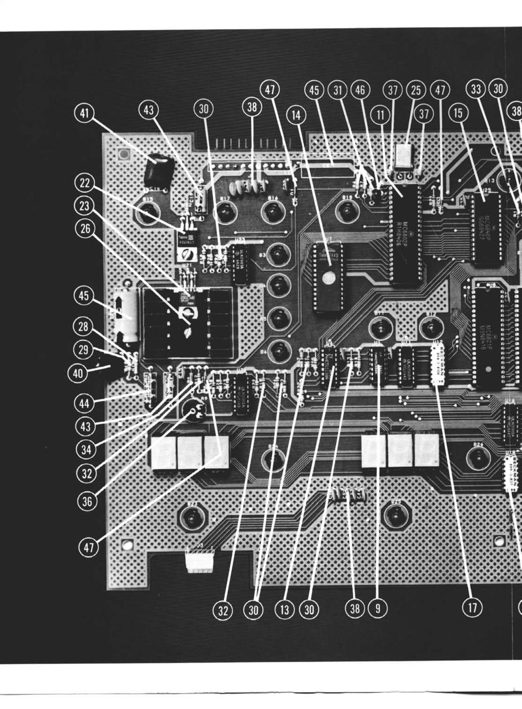
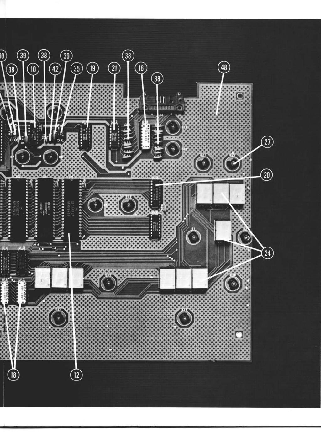
5 FIG. # ITEM # PART # MAIN P.C. BOARD ASSEMBLY Transistor Network - HLN2003A (7) Transistor Network - UDN2580A 21 1 g-0020 Diode Network - TND MC781 5CT LM383T DESCRIPTION 74LSO (4) (Y 74LS A 6840 Resistor Network - 2K ohm Resistor Network - 1 OK ohm Resistor Network - 10 ohm (2) Seven Segment Display (16) Crystal MHz Heat Sink Lamp With Socket (30) Resistor ohm l/4 W Resistor ohm % W Resistor - 1 K ohm l/4 W (19) Resistor - 3.3K ohm l/4 W (3) Resistor - 10K ohm 1 4 W (2) Resistor - 12K ohm l/4 W Resistor - 510K ohm l/4 W Resistor - 1 MEG ohm l/4 W (2) Resistor - 10K ohm Variable Capacitor 27pf 16V (2) Capacitor.Ol mfd 50V (39) Capacitor.l mfd 16V (2) Capacitor.22 mfd 16V Capacitor.33 mfd 1OOV Capacitor.47 mfd 16V Capacitor 1 mfd 50V (2) Capacitor 100 mfd 25V Capacitor 1000 mfd 25V (2) Capacitor 4.7 mfd 25V Tantalum 47 1 g-0007 Diode IN41 48 (3) Main P.C. Board Complete 10


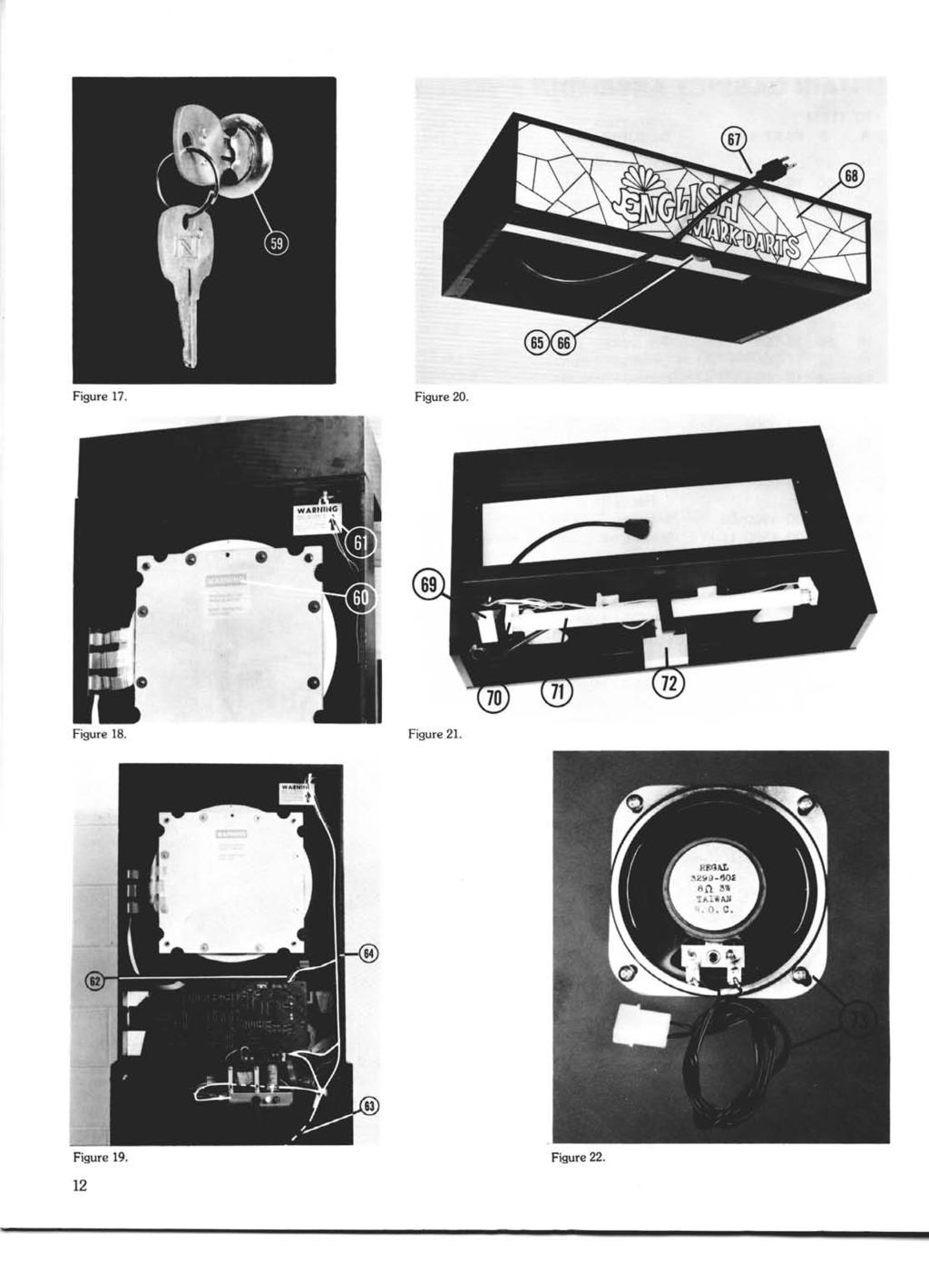
6 MAIN CABINET ASSEMBLY FIG. ITEM # # PART# DESCRIPTION Receptacle Bottom Decal - Lexan Coin Door Assembly With Cash Box Instruction Panel Touch Panel Assembly Top Light Assembly Top Cabinet - Unassembled Top Decal - Lexan Competitor Strip Cabinet Bottom - Unassembled Lock - Back Door Warning Decal - Dart Head Bolts Warning Decal - Receptacle Main Harness Inner Coin Door Harness Receptacle Harness Lamp - 40 W High Intensity Socket - Porcelain Prong Cord - 2% Panel - Marquee Ballast With Built In Starter Socket - Fluorescent (2) Fluorescent Lamp Fl5T8/CW Reflector For Target Lamp Speaker & Harness Figure 16. -NOTE- The part numbers listed are the Arachnid part numbers. Please use these numbers when placing your order. Some descriptions are followed by a number in parentheses. This number is the quantity used in that assembly. Figur 11
7
 Regulator - 5V Heat Sink - TO3 FIG.")

8 Figure 23. _ Figure 24 FIG. ITEM # # PART# DESCRIPTION oo Fuse - WA 250V Slow Blow Fuse - 5A 250V Slow Blow Fuse Clips - P.C. Mount (4) Regulator - 5V Heat Sink - TO3 FIG. ITEM # # PART# DESCRIPTION Power Cord - 12 Switch - On/Off Fuse Holder - Chassis Mount Fuse - 1.5A 250V Slow Blow Capacitor 8900 mfd 25V Heat Sink - Square Printed Circuit Assy. - TOP Bridge Rectifier 8A 200 PIV Triac - SC Bridge Rectifier 2A 200 PIV Opto Isolator - MOC lo-0035 Connector - 10 PIN Resistor ohm %I W Capacitor.Ol mfd 50V (2) Resistor ohm l/4 W Capacitor.33 mfd 1 OOV Capacitor 4700 mfd 35V Transformer - 115V Primary Connector - 6 Pin Chassis Mount Strain Relief Figure 25. POWER SUPPLY CHASSIS ASSEMBLY Resistor - 1 K ohm l/4 W Capacitor.022 mfd 600V (2) Varsitor V150LA20A Standoffs 5/8 (3) Printed Circuit Assy. - BOTTOM 13


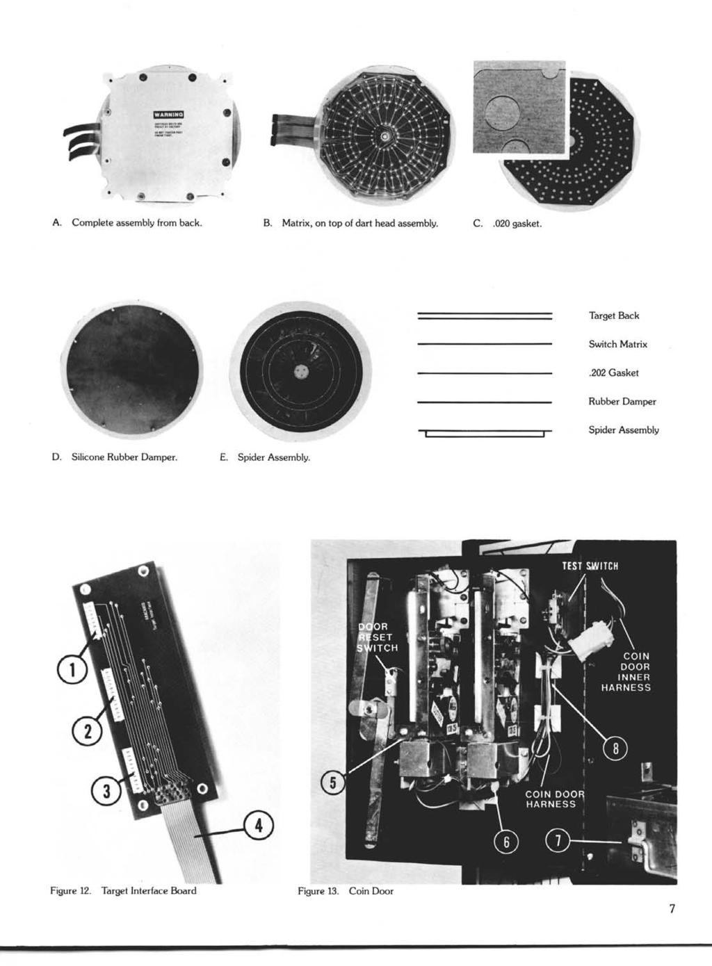
9 Figure 26. Figure 27. Figure 28. BOARD SEGMENTS FIG. ITEM # # PART# DESCRIPTION A Segment - Red - Double A Segment - Black - Double C Segment - Red - Single C Segment - Black - Single D Segment - Red - Triple D Segment - Black - Triple E. Segment - Red - Pie - Single E Segment - Black - Pie - Single B Segment - Red - Bullseye TARGET ASSEMBLY FIG. ITEM # # PART# DESCRIPTION Spider Without Segments Rubber Damper Gasket Switch Matrix - 6 Leads Target Back Dart Head Assy. - Complete
10 SECTION 7. TROUBLESHOOTING WARNING - UNPLUG POWER TO GAME BEFORE WORKING ON MACHINE Problem Probable Cause Procedure Nothing lit on game. a. Blown fuse. b. No power at outlet. a. Replace fuse in power supply chassis with ISA 250V slow blow fuse. b. Check main breaker in building. Marquee lit but nothing else (possibly the temporary score lamps) a. Fuse FSI on top of power supply blown. b. 5 volt regulator bad. a. Replace fuse with 5A 25OV slow blow. b. check for lamp voltage and +5V. If lamp voltage is OK but +5V is not present, replace 5V regulator LM 323K. c. Game not turned on. c. Turn on switch located on power supply Two 7 segment displays light up very bright with 88 a. U2 556 timer not putting out 1000 Hz interrupt signal. b. One segment of U19 shorted, causing 2 digits to always be on. a. Replace 556 IC U2 b. Replace UDN2580 U19 c. One output line of U9 latched on. c. Try resetting game (slam switch in coin door) or replace U9 (6821). A single segment is out on every a. A driver transistor is bad (U15 a. Swap U15 and U16 to see if problem switches from even other display. for odd # displays, U16 for even # to odd (or vice-versa). If so, replace U15 or U16. displays). b. Bad current limit resistor (U17 for odd # displays, U18 for even # displays). b. Swap U17 and U18 as above. If problem switches, replace U17 or U18. c. If only one segment in one display is c. Replace the seven segment display. bad, then the display itself is bad. Player change and/or game select a. Bad 6821 a. Replace switches not functioning. b. Front touch panel not plugged in or broken connector. b. Plug in or replace front panel. Coin switch and/or test mode not functioning. a. If both are not working, plus lamps on a. Repair ground NOTE: System ground is floating (not coin door are not Ilghting, there may connected to power supply chassis) and is connected only be a bad ground to the coin door. to the PC board on top of the power supply. b. If both are not working, but the b. Swap U4 with to see if the problem goes away; if so, lamps on the coin door are lit, the replace problem could be U e. If lust one switch isn t working, c. Swap U23 and U24 to se if the problem changes. If so, check buffer IC s: U23 for the coin replace the bad ULN2003. switch, U24 for the test mode. Small lamps on prlnted circuit hoard not lighting. a. Lamp burned out. il. Replace lamp. b. Transistor driver for lamp bad. c. Peripheral interface adapter (PIA) bad. b. Replace drive see Table 2 c. Replace PIA see Table 2. 15
. c. Opto isolator (MOC3030) bad. d. Buffer U24 bad. e. PIA U9 bad (6821). a. Replace lamp. b. Replace triac located under power supply chassis.")
11 SECTION 7. TROUBLESHOOTING (continued) WARNING - UNPLUG POWER TO GAME BEFORE WORKING ON MACHINE Problem Probable Cause Procedure Target lamp not lighting. a. Lamp burned out. b. Triac bad (if triac were shorted the lamp would be on all the time). c. Opto isolator (MOC3030) bad. d. Buffer U24 bad. e. PIA U9 bad (6821). a. Replace lamp. b. Replace triac located under power supply chassis. c. Replace located under power supply chassis. d. Replace U24. (ULN2003) e. Swap with U4,5, or to check. If problem moves, then replace bad PIA. Sound problems a. Blown fuse FS2 on top of power supply. b. 15V regulator (LM7815CT) faulty on main board. a. Replace with 3/4 A 250V slow blow. b. Check for +24V on pin 1 and +15V on pin 3. If +15V is not present on pin 3, replace regulator. If +24V is zero, replace fuse (FS2 on power supply) or check wiring from power supply to main board. c. Amplifier faulty (LM383T). c. Check input (pin 1) with an oscilloscope to see if square waves are coming in (make sure volume is turned up R9). If no square waves present, see D below. If square waves are present, but not coming out of pin 4, replace U21 LM383T amplifier. d. Timer IC U25 (6840) d. If no square wave is present on pin 27 of U25 (during the time that sound is supposed to be present), replace either U25 or U6 (74LS138 address decoder). e. Sound is fuzzy or garbled bad 4700 mfd 35V capacitor (C2) on power supply board. e. Resolder connections first to make sure that the problem is not a cold solder joint. If no improvement, replace C2. I Top marquee light doesn t light. a. Bulb burned out. a. Replace bulb (F15T8/CW) b. If game also is not working, fuse b. Replace FSl in power supply chassis with 1.5A 250V FSl bad. slow blow. c. Ballast bad. c. Check for 115VAC on input to ballast. If present, then replace ballast. If not, check wiring from power supply (NOTE: starter for lamp is internal to ballast and is replaced as a unit). No score. a. Dirt or broken tips in dart head a. Clean dart head assembly by disassembling/reassembling holding a switch in the switch matrix and removing any foreign material. When reassembling, closed (game won t score until switch make sure to tighten the 8 screws and nuts that hold the in the matrix opens). target head together only finger tight. b. If the problem is not in the dart head, b. Swap U4 with U5, lj8 or U9 to see if problem changes. If may be U4 (6821) on the main board. it does, replace bad Material Avenue Post Office Box 2901 Rockford, Illinois / or 815/ in Illinois WARNING: This equipment generates, uses, and can radiate radio frequency energy and if not installed and used in accordance with the instruction manual, may cause interference to radio communications. It has been tested and found to comply with the limits for a Class A computing device pursuant to Subpart J of Part 15 of FCC Rules, which are designed to provide reasonable protection against such interference when operated in a commercial environment. Operation of this equipment in a residential area is likely to cause intetlerence, in which case lhe user, al his own expense, will be required to take whatever measure may be reauired lo correct the interference. NOTE: Prover grounding through power cord is necessary f& compliance. 37oool 1985 Arachnid, Inc. Printed in U.S.A.
Build A Video Switcher
 Build A Video Switcher VIDEOSISTEMAS serviciotecnico@videosistemas.com www.videosistemas.com Reprinted with permission from Electronics Now Magazine September 1997 issue Copyright Gernsback Publications,
MASTR II BASE STATION 12/24V POWER SUPPLY 19A149979P1-120 VOLT/60 Hz 19A149979P2-230 VOLT/50 Hz
 Mobile Communications MASTR II BASE STATION 12/24V POWER SUPPLY 19A149979P1-120 VOLT/60 Hz 19A149979P2-230 VOLT/50 Hz CAUTION THESE SERVICING INSTRUCTIONS ARE FOR USE BY QUALI- FIED PERSONNEL ONLY. TO
SAFETY WARNINGS AND GUIDELINES INTRODUCTION CUSTOMER SERVICE
 SAFETY WARNINGS AND GUIDELINES Prior to operation, check the unit and power cord for physical damage. Do not use if physical damage has occurred. Before plugging the unit into a power outlet, ensure that
SAFETY WARNINGS AND GUIDELINES INTRODUCTION CUSTOMER SERVICE
 SAFETY WARNINGS AND GUIDELINES Prior to operation, check the unit and power cord for physical damage. Do not use if physical damage has occurred. Before plugging the unit into a power outlet, ensure that
GEKCO SUBCARRIER REFERENCE OSCILLATOR MODEL SRO10 OPERATION/SERVICE MANUAL
 GEKCO MODEL SRO10 SUBCARRIER REFERENCE OSCILLATOR OPERATION/SERVICE MANUAL GEKCO Labs PO Box 642 Issaquah, WA 98027 (425) 392-0638 P/N 595-431 REV 5/98 Copyright c 1998 GEKCO Labs All Rights Reserved Printed
DIY KIT MHZ 8-DIGIT FREQUENCY METER
 This kit is a stand-alone frequency meter capable of measuring repetitive signals up to a frequency of 50MHz. It has two frequency ranges (15 and 50 MHz) as well as two sampling rates (0.1 and 1 second).
USER S MANUAL
 612720 USER S MANUAL SAFETY WARNINGS AND GUIDELINES Prior to operation, check the unit and power cord for physical damage. Do not use if physical damage has occurred. Before plugging the unit into a power
Bill of Materials: Super Simple Water Level Control PART NO
 Super Simple Water Level Control PART NO. 2169109 Design a simple water controller in which electrodes are required to sense high and low water levels in a tank. Whenever the water level falls below the
7 SEGMENT LED DISPLAY KIT
 ESSENTIAL INFORMATION BUILD INSTRUCTIONS CHECKING YOUR PCB & FAULT-FINDING MECHANICAL DETAILS HOW THE KIT WORKS CREATE YOUR OWN SCORE BOARD WITH THIS 7 SEGMENT LED DISPLAY KIT Version 2.0 Which pages of
AS-300D Series Smart Bench Scales Owner s Manual
 DETE CTO A Division of Cardinal Scale Manufacturing Co. AS-300D Series Smart Bench Scales Owner s Manual 8527-M214-O1 Rev B 01/03 PO BOX 151 WEBB CITY, MO 64870 417-673-4631 Printed in USA INTRODUCTION
16 Stage Bi-Directional LED Sequencer
 16 Stage Bi-Directional LED Sequencer The bi-directional sequencer uses a 4 bit binary up/down counter (CD4516) and two "1 of 8 line decoders" (74HC138 or 74HCT138) to generate the popular "Night Rider"
MONO AMPLIFIER KIT ESSENTIAL INFORMATION. Version 2.2 CREATE YOUR OWN SPEAKER DOCK WITH THIS
 ESSENTIAL INFORMATION BUILD INSTRUCTIONS CHECKING YOUR PCB & FAULT-FINDING MECHANICAL DETAILS HOW THE KIT WORKS CREATE YOUR OWN SPEAKER DOCK WITH THIS MONO AMPLIFIER KIT Version 2.2 Build Instructions
Power Injector 1520 Series
 Power Injector 1520 Series Technical Specifications Input voltage 100 to 240 VAC Output voltage 56.0 VDC Voltage range tolerance 54 VDC to 57 VDC Maximum current 1.43 A No load current 15 ma 56VDC@0.71A
NewScope-7A Operating Manual
 2016 SIMMCONN Labs, LLC All rights reserved NewScope-7A Operating Manual Preliminary May 13, 2017 NewScope-7A Operating Manual 1 Introduction... 3 1.1 Kit compatibility... 3 2 Initial Inspection... 3 3
Model 1421 Distribution Amplifier
 Model 1421 Distribution Amplifier Installation and Operating Instructions The 1421 Distribution Amplifier provides four independent, wide bandwidth outputs from one video input. The unit is color compatible
Industrial Monitor Update Kit
 Industrial Monitor Update Kit (Bulletin Number 6157) Installation Instructions 2 Table of Contents Table of Contents Industrial Monitor Update Kit... 3 Overview... 3 Part 1 - Initial Preparation... 5 Part
USER MANUAL. 27" 2K QHD LED Monitor L27HAS2K
 USER MANUAL 27" 2K QHD LED Monitor L27HAS2K TABLE OF CONTENTS 1 Getting Started 2 Control Panel/ Back Panel 3 On Screen Display 4 Technical Specs 5 Troubleshooting 6 Safety Info & FCC warning 1 GETTING
Multi-Key v2.4 Multi-Function Amplifier Keying Interface
 Multi-Key v2.4 Multi-Function Amplifier Keying Interface ASSEMBLY & OPERATION INSTRUCTIONS INTRODUCTION The Harbach Electronics, LLC Multi-Key is a multi-function external device designed for the safe
In-Ceiling Electric Motorized Front Projection Screen Evanesce Series. User s Guide
 In-Ceiling Electric Motorized Front Projection Screen Evanesce Series User s Guide Important Safety & Warning Precautions Make sure to read this user s guide and follow the procedures below. Caution: The
USER MANUAL. 27 Full HD Widescreen LED Monitor L270E
 USER MANUAL 27 Full HD Widescreen LED Monitor L270E TABLE OF CONTENTS 1 Getting Started 2 Control Panel/ Back Panel 3 On Screen Display 4 Technical Specs 5 Care & Maintenance 6 Troubleshooting 7 Safety
USER MANUAL. 28" 4K Ultra HD Monitor L28TN4K
 USER MANUAL 28" 4K Ultra HD Monitor L28TN4K TABLE OF CONTENTS 1 Getting Started 2 Control Panel/ Back Panel 3 On Screen Display 4 Technical Specs 5 Care & Maintenance 6 Troubleshooting 7 Safety Info &
PNP300 & PNP350 POP N PLUG SLIM INTERCONNECT BOX USER S GUIDE
 The is shown above. MANUAL PART NUMBER: 400-0114-004 & PNP350 POP N PLUG SLIM INTERCONNECT BOX USER S GUIDE TABLE OF CONTENTS Page PRECAUTIONS / SAFETY WARNINGS... 2 GENERAL...2 HANDLING...2 CLEANING...2
SBL Series Wireless Clock Installation Manual (V2) Table of Contents
 Table of Contents") MOUNTING Table of Contents Wall Mount Installation... Page 2 Double Mount Installation...... Page 3-4 WIRING AND JUMPERS Wiring Information and Jumper Settings... Page 5 FREQUENTLY ASKED QUESTIONS SBL
MOUNTING Table of Contents Wall Mount Installation... Page 2 Double Mount Installation...... Page 3-4 WIRING AND JUMPERS Wiring Information and Jumper Settings... Page 5 FREQUENTLY ASKED QUESTIONS SBL
USER MANUAL. 27 Full HD Widescreen LED Monitor L27ADS
 USER MANUAL 27 Full HD Widescreen LED Monitor L27ADS TABLE OF CONTENTS 1 Getting Started 2 Control Panel/ Back Panel 3 On Screen Display 4 Technical Specs 5 Care & Maintenance 6 Troubleshooting 7 Safety
Contents Section 9, Illustrated Parts
 Contents Section 9, Illustrated Parts Figures 9-1. Parts of RT7... 9-5 9-2. RT7 Drive Assembly... 9-9 9-3. RT7 Refrigeration System... 9-10 9-4. Parts of RT7 PLUS... 9-15 9-5. RT7 PLUS Drive Assembly...
ACCESSORIES MANUAL PART NUMBER: PRODUCT REVISION: 1 PNP202. Interconnect Box USER'S GUIDE
 MANUAL PART NUMBER: 400-0109-001 PRODUCT REVISION: 1 PNP202 Interconnect Box USER'S GUIDE INTRODUCTION Your purchase of the PNP202 Interconnect Box is greatly appreciated. We are sure you will find it
Specifications. End-Point Linearity - ±5% F.S., when used with HACO SCR-speed control
 Specifications Model 552 Catalog No. Model Power 55-0665 552 115 VAC, 50-60 Hz 55-0673 552A 230 VAC, 50-60 Hz Input - Single-ended, DC coupled 0 to +10V. Signal source can be Floating (not referenced to
Olympus BHM Microscope LED Illumination Andrew Menadue, UK
 Olympus BHM Microscope LED Illumination Andrew Menadue, UK I'm involved with electronics, both at work and at home and now and again I blow up an integrated circuit or have some dismantled equipment with
ModWright Instruments, Inc. PH 150 Tube Phono Stage Owner s Manual
 ModWright Instruments, Inc. PH 150 Tube Phono Stage Owner s Manual Manufactured by ModWright Instruments, Inc. 21919 399th St., Amboy, WA 98601 USA www.modwright.com 1 CAUTIONS: Do not operate or power
Total solder points: 123 Difficulty level: beginner 1. advanced AUDIO ANALYZER K8098. audio gea Give your. . high-tech ILLUSTRATED ASSEMBLY MANUAL
 Total solder points: 123 Difficulty level: beginner 1 2 3 4 5 advanced AUDIO ANALYZER K8098 ra audio gea Give your. look high-tech ILLUSTRATED ASSEMBLY MANUAL H8098IP-1 Features & Specifications Features
COLOUR CHANGING USB LAMP KIT
 TEACHING RESOURCES SCHEMES OF WORK DEVELOPING A SPECIFICATION COMPONENT FACTSHEETS HOW TO SOLDER GUIDE SEE AMAZING LIGHTING EFFECTS WITH THIS COLOUR CHANGING USB LAMP KIT Version 2.1 Index of Sheets TEACHING
QUIZ BUZZER KIT TEACHING RESOURCES. Version 2.0 WHO ANSWERED FIRST? FIND OUT WITH THIS
 TEACHING RESOURCES SCHEMES OF WORK DEVELOPING A SPECIFICATION COMPONENT FACTSHEETS HOW TO SOLDER GUIDE WHO ANSWERED FIRST? FIND OUT WITH THIS QUIZ BUZZER KIT Version 2.0 Index of Sheets TEACHING RESOURCES
Arbor Scientific PO Box 2750 Ann Arbor, Michigan (800) Timer & Photogates 2.0 P Owners Manual
 Timer & Photogates 2.0 P Owners Manual") Arbor Scientific PO Box 2750 Ann Arbor, Michigan 48108 www.arborsci.com (800) 367-6695 Timer & Photogates 2.0 P4-1450 Owners Manual Stopwatch 0.01 second resolution to 999999.99 seconds Count FCC Compliance
Arbor Scientific PO Box 2750 Ann Arbor, Michigan 48108 www.arborsci.com (800) 367-6695 Timer & Photogates 2.0 P4-1450 Owners Manual Stopwatch 0.01 second resolution to 999999.99 seconds Count FCC Compliance
Tube Cricket Build Guide
 Tube Cricket Build Guide The Tube Cricket is a small-wattage amp that puts out about 1 watt of audio power. With a 12AU7 tube-preamp and a JRC386 power amp, the Tube Cricket gives you great tone in a compact
Massachusetts Institute of Technology Department of Electrical Engineering and Computer Science
 Massachusetts Institute of Technology Department of Electrical Engineering and Computer Science 6.111 - Introductory Digital Systems Laboratory Project Resources Project resources are allocated on a per
Documentation VFD clock 8 a clock
 Documentation VFD clock 8 a clock This documentation is protected by our copyright. It must not be used for commercial purposes. Congratulations on your purchase of your VFD clock. To guarantee success
Mal-2 assembly guide v1.0
 Mal-2 assembly guide v.0 SONIC POTIONS Schematic and BOM The BOM can be found on Google Docs Prepare the PCB Separate the PCBs using some pliers. PCB We start with the lower PCB and assemble it beginning
Introduction 1. Digital inputs D6 and D7. Battery connects here (red wire to +V, black wire to 0V )
") Introduction 1 Welcome to the magical world of GENIE! The project board is ideal when you want to add intelligence to other design or electronics projects. Simply wire up your inputs and outputs and away
Introduction 1 Welcome to the magical world of GENIE! The project board is ideal when you want to add intelligence to other design or electronics projects. Simply wire up your inputs and outputs and away
M SERIES DISPENSER M SERIES DISPENSER
 M SERIES DISPENSER PART NUMBER 5006621 M SERIES DISPENSER M SERIES DISPENSER... M - 1 M15 TOP EXPLODED VIEW... M - 2 M15 TOP PARTS LIST... M - 3 M15 BASE EXPLODED VIEW... M - 4 M15 BASE PARTS LIST... M
Summit Systems Sound Board Modification
 Summit Systems Sound Board Modification The Summit slots fitted with the music feature play two sounds; one when the coin is inserted, and the other that plays as winning coins pass through the hopper
USER MANUAL Full HD Widescreen LED Monitor L215ADS
 USER MANUAL 21.5 Full HD Widescreen LED Monitor L215ADS TABLE OF CONTENTS 1 Getting Started 2 Control Panel/ Back Panel 3 On Screen Display 4 Technical Specs 5 Care & Maintenance 6 Troubleshooting 7 Safety
Model 6010 Four Channel 20-Bit Audio ADC Data Pack
 Model 6010 Four Channel 20-Bit Audio ADC Data Pack Revision 3.1 SW v1.0.0 This data pack provides detailed installation, configuration and operation information for the Model 6010 Four Channel 20-bit Audio
19 / 20.1 / 22 WIDE SCREEN TFT-LCD MONITOR
 19 / 20.1 / 22 WIDE SCREEN TFT-LCD MONITOR V193/ V220 Series V202 Series USER MANUAL www.viewera.com Rev. 2.0 Table of Contents EMC Compliance......1 Important Precautions...2 1. Package contents....3
PLL1920M LED LCD Monitor
 PLL1920M LED LCD Monitor USER'S GUIDE www.planar.com Content Operation Instructions...1 Safety Precautions...2 First Setup...3 Front View of the Product...4 Rear View of the Product...5 Installation...6
USER MANUAL Full HD Widescreen LED Monitor L215IPS
 USER MANUAL 21.5 Full HD Widescreen LED Monitor L215IPS TABLE OF CONTENTS 1 Getting Started 2 Control Panel/ Back Panel 3 On Screen Display 4 Technical Specs 5 Care & Maintenance 6 Troubleshooting 7 Safety
Assembly Instructions And User Guide. Nixie FunKlock. FunKlock Issue 4 (1 February 2017)
") Assembly Instructions And User Guide Nixie FunKlock - 1 - Issue Number Date REVISION HISTORY 4 1 February 2017 New diode for D2 3 27 December 2013 C7 / C8 error page 15 2 7 November 2013 Errors corrected
Assembly Instructions And User Guide Nixie FunKlock - 1 - Issue Number Date REVISION HISTORY 4 1 February 2017 New diode for D2 3 27 December 2013 C7 / C8 error page 15 2 7 November 2013 Errors corrected
instruction manual model 315 video sync separator s/n
 instruction manual model 315 video sync separator s/n colorado video, inc boulder, colorado january 2016 WARNING This equipment generates, uses and can radiate radio frequency energy and if not installed
VLC-3 USER'S MANUAL. Light Program Controller. M rev. 04 K rev. 00 & ( ( 5, 352*5$0 1 : $ 2 ' 6(77,1*6 )81&7,216
81&7,216") Light Program Controller VLC-3 USER'S MANUAL +50,1 +50,1 1 : $ ' 2 7. 6 8 ' 5, 7 6 6. $ ( 3 352*5$0 0,16(& )81&7,216 6(77,1*6 & 8 5 5 ( 1 7 3 ( 5, 2 ' M 890-00189 rev. 04 K 895-00406 rev. 00 GENERAL...
Light Program Controller VLC-3 USER'S MANUAL +50,1 +50,1 1 : $ ' 2 7. 6 8 ' 5, 7 6 6. $ ( 3 352*5$0 0,16(& )81&7,216 6(77,1*6 & 8 5 5 ( 1 7 3 ( 5, 2 ' M 890-00189 rev. 04 K 895-00406 rev. 00 GENERAL...
Chapter 18. DRAM Circuitry Discussion. Block Diagram Description. DRAM Circuitry 113
 DRAM Circuitry 113 Chapter 18 DRAM Circuitry 18-1. Discussion In this chapter we describe and build the actual DRAM circuits in our SK68K computer. Since we have already discussed the general principles
AWT150C/AWT150CS/ AWT151C CCD Camera
 AWT150C/AWT150CS/ AWT151C CCD Camera ISSUED OCTOBER 2018 WARNING Failure to follow all instructions and safety precautions in this manual, in the vehicle and body manufacturers' manuals and on the safety
Step What to do Expected result What to do if test fails Component tested 1 Visual inspection. Board is accurately assembled
 Fox Delta Amateur Radio Projects & Kits AAZ-0914A 50MHZ Antenna Analyzer Testing Guide by Tony / I2TZK SWR Analyzer 4 steps for a quick test Step What to do Expected result What to do if test fails Component
VPS 100 YPSILON PHONO STAGE. OWNERS MANUAL V1 01/01/2010 All rights reserved
 VPS 100 YPSILON PHONO STAGE OWNERS MANUAL V1 01/01/2010 All rights reserved INTRODUCTION Thank you for trusting YPSILON ELECTRONICS. We assure you that you have made an excellent purchase. Your phono stage
Intellivision Master Component Owner's Manual
 Intellivision Master Component Owner's Manual CONTENTS How to Connect the Antenna Switchbox Set Up Your Master Component How to Insert the Cartridge How to Use the Master Component The Intermission Code
Mapletree Audio Design
 Ultra 4C Preamplifier Mapletree Audio Design Ultra 4C Stereo Phono/Line Preamplifier PS 2D Power Supply User s Manual Rev. Mar. 22, 2019 Mapletree Audio Design R. R. 1, Seeley's Bay, Ontario, Canada, K0H
ZvBox 150. HD video distribution over COAX Get Going Guide
 ZvBox 150 HD video distribution over COAX Get Going Guide ZvBox 150 is an HD MPEG 2 Encoder and frequency agile QAM Modulator. It allows you to convert any HD video source, Component or RGB (VGA), in real
RoHS. Atma-Sphere Music Preamplifier. model P-2 OWNER'S MANUAL. Please study this document carefully before using equipment
 1742 Selby Av. St. Paul, MN 55104 651 690 2246 atma sphere.com Atma-Sphere Music Preamplifier model P-2 OWNER'S MANUAL Please study this document carefully before using equipment RoHS CONGRATULATIONS!
4830A Accelerometer simulator Instruction manual. IM4830A, Revision E1
 4830A Accelerometer simulator Instruction manual IM4830A, Revision E1 IM4830, Page 2 The ENDEVCO Model 4830A is a battery operated instrument that is used to electronically simulate a variety of outputs
Introduction 1. Green status LED, controlled by output signal ST. Sounder, controlled by output signal Q6. Push switch on input D6
 Introduction 1 Welcome to the GENIE microcontroller system! The activity kit allows you to experiment with a wide variety of inputs and outputs... so why not try reading sensors, controlling lights or
USER MANUAL Full HD Widescreen LED Monitor L236VA
 USER MANUAL 23.6 Full HD Widescreen LED Monitor L236VA TABLE OF CONTENTS 1 Getting Started 2 Control Panel/ Back Panel 3 On Screen Display 4 Technical Specs 5 Care & Maintenance 6 Troubleshooting 7 Safety
Digital Clock. Perry Andrews. A Project By. Based on the PIC16F84A Micro controller. Revision C
 Digital Clock A Project By Perry Andrews Based on the PIC16F84A Micro controller. Revision C 23 rd January 2011 Contents Contents... 2 Introduction... 2 Design and Development... 3 Construction... 7 Conclusion...
MONOPRICE. Foldable Long Range HD8 Outdoor HD Antenna. User's Manual P/N 24172
 MONOPRICE Foldable Long Range HD8 Outdoor HD Antenna P/N 24172 User's Manual INTRODUCTION Thank you for purchasing this Foldable Long-Range HD8 Outdoor HD Antenna! This antenna has a maximum range of up
 Register your product and get support at www.philips.com/welcome SWS3435S/27 SWS3435H/37 EN User manual Contents 1 Important 4 Safety 4 English 2 Your SWS3435 6 Overview 6 3 Installation 7 Connect the
USER MANUAL. 22" Class Slim HD Widescreen Monitor L215DS
 USER MANUAL 22" Class Slim HD Widescreen Monitor L215DS TABLE OF CONTENTS 1 Getting Started Package Includes Installation 2 Control Panel / Back Panel Control Panel Back Panel 3 On Screen Display 4 Technical
While the parts are already inventoried at the factory, please verify the inventory check as you go:
 Thank you for purchasing the kit for building the WJ9J DTMF controller. After building, you should read the document on operation (WJ9JDTMFControllerV5.pdf) in order to use. This is also in the link in
SWITCH: Microcontroller Touch-switch Design & Test (Part 2)
") SWITCH: Microcontroller Touch-switch Design & Test (Part 2) 2 nd Year Electronics Lab IMPERIAL COLLEGE LONDON v2.09 Table of Contents Equipment... 2 Aims... 2 Objectives... 2 Recommended Timetable... 2
SWITCH: Microcontroller Touch-switch Design & Test (Part 2) 2 nd Year Electronics Lab IMPERIAL COLLEGE LONDON v2.09 Table of Contents Equipment... 2 Aims... 2 Objectives... 2 Recommended Timetable... 2
Introduction 1. Green status LED, controlled by output signal ST
 Introduction 1 Welcome to the magical world of GENIE! The project board is ideal when you want to add intelligence to other design or electronics projects. Simply wire up your inputs and outputs and away
PLL2210MW LED Monitor
 PLL2210MW LED Monitor USER'S GUIDE www.planar.com Content Operation Instructions...1 Safety Precautions...2 First Setup...3 Front View of the Product...4 Rear View of the Product...5 Quick Installation...6
Electro Magnetic Compatibility (EMC) Warning. Important notes for users in the U.K. FCC declaration. Caution. Fuse
 Warning. Important notes for users in the U.K. FCC declaration. Caution. Fuse") Warning: to prevent fire or shock hazard, do not expose camera or monitor to rain or moisture. The lightning flash with arrowhead symbol, within a triangle, is intended to alert the user to the presence
Warning: to prevent fire or shock hazard, do not expose camera or monitor to rain or moisture. The lightning flash with arrowhead symbol, within a triangle, is intended to alert the user to the presence
Nixie Clock Type Frank 3
 Assembly Instructions And User Guide Nixie Clock Type Frank 3 Software version: 7R PCB Version: 11 April 09-1 - 1. INTRODUCTION 1.1 About the clock Nixie clock type Frank 3 is a compact design with all
VK-P10SE WARRANTY REGISTRATION FORM
 VK-P10SE WARRANTY REGISTRATION FORM Unit Serial Number: Customer Name: Address: Date of Purchase: Purchased From: Dealer Name: Address: IMPORTANT NOTE: In order to receive the full five-year product warranty,
Disclaimer. Trademarks. Copyright. Contact Us Control4 Corporation S. Election Road Salt Lake City, UT USA
 Disclaimer Trademarks Copyright Control4 makes no representations or warranties with respect to this publication, and specifically disclaims any express or implied warranties of merchantability or fitness
By CHANNEL VISION. Flush Mount Amplifier A0350
 Spkrs Local In IR In 24VDC A0350 10 The A0350 can be used with Channel Vision s CAT5 audio hubs to provide a powerful 50Watts per channel in the listening zone. Alternatively, the A0350 can be added to
MP-7424 Football Scoreboard with MP5000 Console
 MP-7424 Football Scoreboard with MP5000 Console With additional instructions for Track and Soccer Operator s Manual Volume VII Rev. 10/17/07 Table of Contents Table of Contents...2 1.0 Keypad Console...3
TECHNOLOGY WILL SAVE US: THE LUMIPHONE
 TECHNOLOGY WILL SAVE US: THE LUMIPHONE This is a step-by-step guide to soldering your own Lumiphone. The equipment you should have at your station: goggles, soldering mat, soldering Iron, solder and side
Sphinx II. Owner s Manual. Tube Hybrid Integrated Power Amplifier. Rogue Audio, Inc. 3 Marian Lane Brodheadsville, PA Issue date: 08/01/16
 Sphinx II Tube Hybrid Integrated Power Amplifier Owner s Manual Rogue Audio, Inc. 3 Marian Lane Brodheadsville, PA 18322 Issue date: 08/01/16 TABLE OF CONTENTS 1) Introduction 2 2) Unpacking the Sphinx
"shell" digital storage oscilloscope (Beta)
") "shell" digital storage oscilloscope (Beta) 1. Main board: solder the element as the picture shows: 2. 1) Check the main board is normal or not Supply 9V power supply through the connector J7 (Note: The
"shell" digital storage oscilloscope (Beta) 1. Main board: solder the element as the picture shows: 2. 1) Check the main board is normal or not Supply 9V power supply through the connector J7 (Note: The
PowerWave PW1A Panel and Wall-Mount Models Installation Guide AV69006-XXX
 PowerWave PW1A Panel and Wall-Mount Models Installation Guide 8820-00063 AV69006-XXX Table of Contents Table of Contents sections 1 2 3 4 5 6 7 8 9 1. Introduction............................................
Nixie Clock Type Frank 2 Z570M
 Assembly Instructions And User Guide Nixie Clock Type Frank 2 Z570M Software version: 7R PCB Revision: 11 April 09-1 - 1. INTRODUCTION 1.1 About the clock Nixie clock type Frank 2 is a compact design with
USER GUIDE. DM Engineering Multi Station Relay Adapter (MSRA and MSRA-RM) Version DM Engineering
 Version DM Engineering") USER GUIDE DM Engineering Multi Station Relay Adapter (MSRA and MSRA-RM) Version 1.35 DM Engineering 2174 Chandler St. Camarillo, CA 91345-4611 805-987-7881 800-249-0487 www.dmengineering.com Overview:
USER GUIDE DM Engineering Multi Station Relay Adapter (MSRA and MSRA-RM) Version 1.35 DM Engineering 2174 Chandler St. Camarillo, CA 91345-4611 805-987-7881 800-249-0487 www.dmengineering.com Overview:
Christmas LED Snowflake Project
 Christmas LED Snowflake Project Version 1.1 (01/12/2008) The snowflake is a follow-on from my Christmas star project from a few years ago. This year I decided to make a display using only white LEDs, shaped
Regenerating Tissues
 Regenerating Tissues Exhibit Description: Regenerating Tissues is a stand-alone interactive component of the Nanomedicine exhibition. A copy panel describes how Nanomaterials are able to form tiny structures
PL2410W LCD Monitor USER'S GUIDE.
 PL2410W LCD Monitor USER'S GUIDE www.planar.com Content Operation Instructions...1 Safety Precautions...2 First Setup...3 Front View of the Product...4 Rear View of the Product...5 Quick Installation...6
HD Digital MPEG2 Encoder / QAM Modulator
 HD Digital MPEG2 Encoder / QAM Modulator YPrPb VGA In QAM Out series Get Going Guide ZvPro 600 Series is a one or two-channel Component or VGA-to-QAM MPEG 2 Encoder/ Modulator, all in a compact package
28 & 32 & 40 & 55 & 65 & 84-INCH TFT-LCD 4K MONITOR
 28 & 32 & 40 & 55 & 65 & 84-INCH TFT-LCD 4K MONITOR INSTRUCTION MANUAL Please read this manual thoroughly before use, and keep it handy for future reference. TABLE OF CONTENTS 1, General information...
Engineering Design Assurance Test Report ( Dual & Triple ) MODEL: SPS-100P-D2 V1 5 V 12 Amax
 MODEL: SPS-100P-D2 V1 5 V 12 Amax") TEST EQUIPMENT LIST: AC Source : Chroma programmable AC source Model 61504 Power Analyzer : Chroma Power Analyzer Model 6630 Load : Chroma Electronic DC Load 63103 Oscilloscope : Lecroy wave surfer 424
TEST EQUIPMENT LIST: AC Source : Chroma programmable AC source Model 61504 Power Analyzer : Chroma Power Analyzer Model 6630 Load : Chroma Electronic DC Load 63103 Oscilloscope : Lecroy wave surfer 424
User s Manual. Document # , Rev 1.2, 6/12/2006
 CAMERA LINK TM VIDEO SPLITTER User s Manual Document # 200205, Rev 1.2, 6/12/2006 Vivid Engineering 418 Boston Turnpike #104 Shrewsbury, MA 01545 Phone 508.842.0165 Fax 508.842.8930 www.vividengineering.com
DL-1A. RF dummy load - 50Ω 20W. Assembly manual. Last update: May 1, Thank you for constructing the DL-1A dummy load kit
 DL-1A RF dummy load - 50Ω 20W Assembly manual Last update: May 1, 2016 ea3gcy@gmail.com Updates and news at: www.qsl.net/ea3gcy Thank you for constructing the DL-1A dummy load kit Have fun assembling it
TFT-LCD Color Monitor FS-L4201C
 User Manual English TFT-LCD Color Monitor FS-L4201C www.tandberg.net Printed in Korea Part No. 942667020001-01 INFORMATION TO USER : This equipment has been tested and found to comply with the limits of
SignalOn Series. L-Band Splitter Module INSTALLATION & OPERATION MANUAL. 1.2 GHz. D3.
 SignalOn Series D3.1/CCAP Compliant 1.2 GHz L-Band Splitter Module INSTALLATION & OPERATION MANUAL www.atxnetworks.com www.atxnetworks.com Although every effort has been taken to ensure the accuracy of
Table of Contents. Read This First.2. Introduction by Jim Fosgate...3. Unpacking..4. Tubes and Tube shield Installation 5. Product Placement...
 Owner s Manual Table of Contents Read This First.2 Introduction by Jim Fosgate...3 Unpacking..4 Tubes and Tube shield Installation 5 Product Placement...6 Connecting your Fosgate Signature..7 Phono stage
DEM 9ULNACK 3.4 GHz. PHEMT LNA amplifier complete kit assembly guide
 DEM 9ULNACK 3.4 GHz. PHEMT LNA amplifier complete kit assembly guide SPECIFICATIONS Noise Figure: < 0.8 db Gain: > 15 db Frequency Range: 3400-3500 MHz Input Voltage: 7-16 VDC Description: The 9ULNACK
instruction manual video scan reverser models NVCN422CS & NVCN422C
 instruction manual video scan reverser models NVCN422CS & NVCN422C s/n boulder, colorado WARNING This equipment generates, uses and can radiate radio frequency energy and if not installed and used in accordance
Model /29S RF Splitter
 Instruction Manual Model 1584-29/29S RF Splitter March 2013, Rev. 0 LNB VOLTAGE A B MODEL 1584 COMBINER CROSS TECHNOLOGIES INC. GND+DC ON Data, drawings, and other material contained herein are proprietary
University of Illinois at Urbana-Champaign
 University of Illinois at Urbana-Champaign Digital Electronics Laboratory Physics Department Physics 40 Laboratory Experiment 3: CMOS Digital Logic. Introduction The purpose of this lab is to continue
Content. User s Manual 3. Owner s Manual Ver. 1.1 / June Introduction...4. Mytek Package Content Features...
 Owner s Manual User s Manual 3 Content Owner s Manual Ver. 1.1 / June 2018 Mytek 2017 The Brooklyn AMP firmware can be easily updated via Mytek USB Control Panel. As the firmware is updated, Mytek will
MONOPRICE. BitPath AV VGA Extender over Single Cat6 Cable, 120m. User's Manual P/N 16226
 MONOPRICE BitPath AV VGA Extender over Single Cat6 Cable, 120m P/N 16226 User's Manual SAFETY WARNINGS AND GUIDELINES Please read this entire manual before using this device, paying extra attention to
STD-525T PRECISION TIMER
 FN:STD525TM1.DOC STD-525T PRECISION TIMER DESCRIPTION The STD-525T Precision Timer measures and displays accurate elapsed time in minutes, seconds, tenths of seconds, and hundredths of seconds (MM.SS.TH)
S/PDIF & USB D/A Converter. User Manual. Rev.A3, May 2010 Audial d.o.o Belgrade, Serbia
 S/PDIF & USB D/A Converter User Manual Rev.A3, May 2010 Audial d.o.o Belgrade, Serbia www.audialonline.com, info@audialonline.com IMPORTANT PRECAUTIONS 1. Make sure you use earthed mains socket and three
VU-1 VU Meter Kit Volume Unit Meter
 VU-1 VU Meter Kit Volume Unit Meter Simplicity Counts, Detail Matters. No part of this document may be reproduced, either mechanically or electronically, posted online on the Internet, in whole or in part,
apple Service Source Apple Cinema HD Display 23" LCD (ADC) 11 April Apple Computer, Inc. All rights reserved.
 11 April Apple Computer, Inc. All rights reserved.") apple Service Source Apple Cinema HD Display 23" LCD (ADC) 11 April 2003 2003 Apple Computer, Inc. All rights reserved. apple Service Source Take Apart Apple Cinema HD Display 23" LCD (ADC) 2003 Apple
apple Service Source Apple Cinema HD Display 23" LCD (ADC) 11 April 2003 2003 Apple Computer, Inc. All rights reserved. apple Service Source Take Apart Apple Cinema HD Display 23" LCD (ADC) 2003 Apple