!"!3
|
|
|
- Sabina Little
- 5 years ago
- Views:
Transcription


1
2 Abstract A single-mode 500 MHz superconducting cavity cryomodule has been developed at Cornell for the electronpositron collider/synchrotron light source CESR. The Cornell B-cell cavity belongs to the first generation of high-power, HOM-damped accelerating cavities designed to support high average beam currents in storage rings. The B-cell cryomodule is the key component of a four-cavity CESR RF system, which can support total beam current of several hundreds milliamperes. The Cornell design has been transferred to industry and the cryomodules are now available as turn-key systems. In this presentation we will describe main design features of the cryomodule and review operating experience and results obtained since the installation of the first cryomodule in CESR almost a decade ago.
3 Outline Why SRF? History of the Cornell cryomodule development Cryomodule description CESR RF system Operating experience: overcoming initial difficulties Operating experience: quest for high luminosity New challenges: satisfying two different sets of operating conditions (CESR-c and CHESS) Future: CESR-TF ILC damping ring test facility Summary
4 Single-mode cavity concept
5 Why SC cavities are better? 1. Higher accelerating gradients accelerating gradient of n.c. cavities is limited by power dissipation in cavity walls and for 500 MHz cavities it corresponds to 1 MV/cell (SLAC B-factory singlecell cavity) higher accelerating voltage per cell (up to 3 MV) of s.c. cavities fewer number of cells less total impedance 2. Larger beam tubes due to the power dissipation limit in n.c. cavities they have to have high R/Q of fundamental mode re-entrant shape and small beam tubes high R/Qs of HOMs reduced the interaction of the beam with the s.c. cavity HOMs are removed easily lower Q factors better beam stability
 for B physics. CESR had highest luminosity in the world until ~2000, when B-factories surpassed it. SR experiments operated in parasitic mode.")
6 Cornell Electron Storage Ring CESR was built in late 70s for HEP. Both accelerator and detector were upgraded several times. Until 2003 CESR operated in collider mode at high energies (4.7 to 5.6 GeV) for B physics. CESR had highest luminosity in the world until ~2000, when B-factories surpassed it. SR experiments operated in parasitic mode. Original RF system had two 14-cell copper cavities, later replaced with four 5-cell copper cavities. Single cell superconducting cavities were developed for a proposed Cornell B-factory CESR-B and then utilized in CESR-III upgrade (four cavities).
 and TE 111 (650 MHz) Resonant frequency R/Q Q 0 10 9 Qext = Qbeam = 499.")
7 Cornell B-cell cavity Originally developed for Cornell B-factory proposal in early 1990s Fluted beam tube (cut-off frequencies 570 MHz for TE 11 and 932 for TM 01 ) allows propagation of two lowest dipole modes TM 110 (607 MHz) and TE 111 (650 MHz) Resonant frequency R/Q Q Qext = Qbeam = MHz 89 Ohm Q ext 2x10 5 Operating temperature Accelerating field Accelerating voltage Effective cell length Beam tube diameter cut-off frequency (TE 11 ) 4.5 K up to 10 MV/m up to 3 MV 0.3 m 0.24 m 732 MHz Qext was chosen to provide the most efficient operation of RF system at maximum design beam power and cavity voltage (matched conditions, for proposed CESR-B): V 2 c R Q Pbeam

8 Vertical dewar test results BB1-1 cavity was fabricated by Dornier, all others by ACCEL 1.0E+10 After 140ºC, 24 hr. bake BB1-1 BB1-2 BB1-3 BB1-4 BB1-4 after bake BB1-5 BB1-6 BB1-7 SRRC1 SRRC2 CLS1 CLS2 DLS1 DLS2 DLS3 Q 0 1.0E+09 Field emission Quench due to material defect 1.0E V acc [MV]
9 Mark I cryomodule & beam test 1994: Beam test, first demonstration of high current operation Several benchmarks for SRF cavities: Stored beam currents up to 220 ma 155 kw delivered to beam with 165 kw forward power 2 kw of HOM power extracted by ferrite absorbers No resonant excitation of HOMs or beam instabilities were observed Performed critical cavity loss factor and impedance studies The test duration was one week
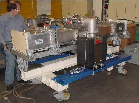
10 Mark II cryomodule The cryostat was redesign to fit into the CESR tunnel


11 Waveguide input coupler Coupling slot WR1800 Kapton window Warm RF window Cold He gas cooled WG Liquid nitrogen cooled WG Pumping section Fixed Q ext = Magnetic bias of the WG to suppress multipacting Adjustability is provided via a 3-stub WG transformer Each window is tested to 400 kw in TW and >125 kw in SW
12 Windows processing
 panels two ferrite tiles (2 1.5 1/8 ) soldered to each panel TT2-111 ferrite each panel is individually tested to power density of 15.5 W/cm 2 f [GHz] f [GHz]")
13 Ferrite HOM load TT2-111 cooling water stainless steel shell cooling panel ferrite tiles (Elkonite) cross-section A-A m modular design 18 water-cooled Elkonite (25% Cu + 75% W) panels two ferrite tiles ( /8 ) soldered to each panel TT2-111 ferrite each panel is individually tested to power density of 15.5 W/cm 2 f [GHz] f [GHz]
14 Loss factor and HOM spectra Calculated spectrum Comparison of prediction with measurements k [V/pC] BB1 Loss Factor Q y = 7.733x R 2 = Prediction e+ 1t1b E1 e+ 1t1b E2 e+ 3t1b E Frequency, GHz e+ 3t1b E2 e+ 9t1b E1 e+ 9t1b E2 e- 1t1b E1 e- 1t1b E2 Fit Measured spectrum E1 cavity E2 cavity W1 cavity W2 cavity 0.2 Q σ [mm] Frequency, G Hz


15 CESR superconducting RF system Beam energy Beam current Frequency Number of cavities R/Q per single-cell cavity Qloaded Accelerating voltage per cavity Klystron power per cavity Number of klystrons Required ampl. stability Required phase stability 1.5 to 5.6 GeV 0 to 500 ma 500 MHz 4 89 Ohm to to 2.4 MV up to 200 kw 2 < 1% < 0.5º
16 RF system diagram
17 CESR cryomodules history B-cell cryomodules in CESR Cryomodule 6 (ACCEL2, BB1-6, E2) (POB and HOM load vacuum leaks repaired) Cryomodule 5 (ACCEL1, BB1-7, W2) Cryomodule 4 (BB1-5, E1, awaiting refurbishing with BB1-2 cavity) (cavity was SS-particle contaminated during assembly, repared, now in Cryomodule 2)) 1999 first storage ring to run entirely on SRF cavities Cryomodule 2 (BB1-3, W2) Cryomodule 3 (BB1-4, E1) Cryomodule 2 (BB1-5, W1) (cavity had non-rapareable material defect that limited accelerating gradient, decommissioned) 1997 Cryomodule 1 (BB1-1, W1, spare) first SRF cavity installed for routine operation (RF probe was installed in wrong location causing very low S/N ratio) Cryomodule 1A (BB1-2, E2, decommissioned) (cryomodule developed He leak into cavity vacuum, cavity will be assembled in Cryomodule 4) Jan-97 Jan-98 Jan-99 Jan-00 Jan-01 Jan-02 Jan-03 Jan-04 Jan-05 Jan-06
 BB1-6 (E2) 1.E+09 1.")
18 Cryomodule test results Q o 1.E+10 BB1-5 (W1) BB1-7 (W2) BB1 Q vs. Eacc Summary BB1-4 (E1) BB1-6 (E2) 1.E+09 1.E V acc [MV]
19 Overcoming initial difficulties (1) The first SC cryomodule installed in CESR was assembled without baking its WG components. The consequence of this was very strong multipacting at forward power levels of 90, 130, 180, kw. We had to develop ways to process this multipacting in situ: 1. Processing with DC magnetic field bias (10 Gauss). 2. High power pulsed processing w/o beam. One can create TW in two ways: very high emitted power for a very short time after RF shut-off due to strongly over-coupled cavity, let cavity quench for ~10 ms at 10% duty cycle. 3. Beam processing by changing RF phase between two RF stations using a specially written software. Further computer simulations confirmed our observations that TW and SW mixing ratio affects multipacting bands.
20 Overcoming initial difficulties (2) After warming up the cryomodule we analyzed residual gas evolution and found that during first 3 months of operation cryomodule cold surfaces accumulated up to 7 equivalent monolayers of hydrogen. During CESR operation we had found that hydrogen plays very important role. Peak # Gas species Cavity HEX Elbow 1 H 2, He 9 K 22 K 85 K 2 CO/N 2, H 2, O 2, Ne 27 K 35 K 92 K 3 CO 2, CO/N 2 83 K 92 K 130 K 4 H 2, H 2 O, CO/N K 165 K 190 K 5 H 2, H 2 O 230 K 220 K 240 K

21 Overcoming initial difficulties (3)


22 Quest for high luminosity CESR was the highest-luminosity collider in pre-b-factory era
23 until ~2012 Post B-physics: CESR-c & CHESS until 2008, then CESR-TF Parameter CHESS CESR-c Energy [GeV] No. of cavities Gradient [MV/m] Voltage [MV] Beam power [MW] Beam current [A] Synch. frequency [khz] Bunch length [mm] relatively high RF power per cavity (160 kw per cavity) emphasis on long beam lifetime, short bunches are not required low RF voltage (1.2 MV/cavity) high luminosity means strong IR focusing and short bunch length (1 cm) high RF voltage ( MV/cavity) low beam energy loss per turn & lower beam current low RF power (10 40 kw per cavity)
24 CESR-c & CHESS operation CHESS beam current CESR-c beam current e- e+ e- e ma Fri, May 25 Sat, May 26 Sun, May 27 Mon, May 28 Time Cavity voltage 0 Sat, April 21 Sun, April 22 Mon, April 23 Time Cavity voltage 2.5 W1 W2 E1 E MV ma 2.5 W1 W2 E1 E MV Fri, May 25 Sat, May 26 Sun, May 27 Mon, May 28 Time 0 Sat, April 21 Sun, April 22 Mon, April 23 Time
25 CESR-c & CHESS operation CHESS CESR-c forward power forward power kw kw W1 W2 E1 E W1 W2 E1 E total beam current, ma Reflected power kw x total beam current, ma Reflected power 123 G58H&9475!35 5 " 5&.6H& G5$H&9475!35 5 " 58H&94 kw x W1 W2 E1 E W1 W2 E1 E total beam current, ma total beam current, ma 75 75!"!3 86
26 Toward ILC: CESR-TF : proposed operation of the CESR-TF Goal: to perform crucial R&D in beam physics and instrumentation for ILC damping ring operability and reliability using a slightly redesigned CESR ring Beam energy 2.0 GeV Total RF voltage 15 MV (will need to add two more cryomodules in 2009) Total beam current ma Number of particles per bunch Bunch length 6.9 mm
27 Summary Cornell has over-10-year experience of using SRF cavities in a high-current storage ring under different operating conditions Even though we had a beam test, its duration was short and the first several months after the first cryomodule installation were very tough, but provided us with invaluable learning experience After overcoming initial difficulties due to mostly multipacting in the rectangular waveguide input coupler/ceramic window region and residual gas evolution, we are able to provide stable and reliable RF system for CESR Successful operation of SRF cavities attracted interest from industry and laboratories and eventually the Cornell technology was transferred to ACCEL, which now provides CESR-type cryomodules to synchrotron light sources world-wide NSSRC/Taiwan Light Source, Canadian Light Source, DIAMOND (UK), SSRF (China) as turn-key systems In the near future we plan to add two more cryomodules to the CESR RF system as part of converting the machine to an ILC damping ring test facility There are many more RF system related developments at Cornell (cryogenic controls, digital RF controls, passive cavity operation, using piezo tuners, experimental and theoretical studies of multipacting, ) that are outside the scope of this presentation
Experience with the Cornell ERL Injector SRF Cryomodule during High Beam Current Operation
 Experience with the Cornell ERL Injector SRF Cryomodule during High Beam Current Operation Matthias Liepe Assistant Professor of Physics Cornell University Experience with the Cornell ERL Injector SRF
PoS(EPS-HEP2015)525. The RF system for FCC-ee. A. Butterworth CERN 1211 Geneva 23, Switzerland
525. The RF system for FCC-ee. A. Butterworth CERN 1211 Geneva 23, Switzerland") CERN 1211 Geneva 23, Switzerland E-mail: andrew.butterworth@cern.ch O. Brunner CERN 1211 Geneva 23, Switzerland E-mail: olivier.brunner@cern.ch R. Calaga CERN 1211 Geneva 23, Switzerland E-mail: rama.calaga@cern.ch
CERN 1211 Geneva 23, Switzerland E-mail: andrew.butterworth@cern.ch O. Brunner CERN 1211 Geneva 23, Switzerland E-mail: olivier.brunner@cern.ch R. Calaga CERN 1211 Geneva 23, Switzerland E-mail: rama.calaga@cern.ch
ILC-LNF TECHNICAL NOTE
 IL-LNF EHNIAL NOE Divisione Acceleratori Frascati, July 4, 2006 Note: IL-LNF-001 RF SYSEM FOR HE IL DAMPING RINGS R. Boni, INFN-LNF, Frascati, Italy G. avallari, ERN, Geneva, Switzerland Introduction For
Diamond RF Status (RF Activities at Daresbury) Mike Dykes
 Mike Dykes") Diamond RF Status (RF Activities at Daresbury) Mike Dykes ASTeC What is it? What does it do? Diamond Status Linac Booster RF Storage Ring RF Summary Content ASTeC ASTeC was formed in 2001 as a centre of
Diamond RF Status (RF Activities at Daresbury) Mike Dykes ASTeC What is it? What does it do? Diamond Status Linac Booster RF Storage Ring RF Summary Content ASTeC ASTeC was formed in 2001 as a centre of
Detailed Design Report
 Detailed Design Report Chapter 4 MAX IV Injector 4.6. Acceleration MAX IV Facility CHAPTER 4.6. ACCELERATION 1(10) 4.6. Acceleration 4.6. Acceleration...2 4.6.1. RF Units... 2 4.6.2. Accelerator Units...
NSLS-II RF Systems James Rose, Radio Frequency Group Leader PAC 2011
 NSLS-II RF Systems James Rose, Radio Frequency Group Leader PAC 2011 1 BROOKHAVEN SCIENCE ASSOCIATES Introduction Linac RF cavities and klystrons Booster Cavity-Transmitter Storage Ring 500 MHz SRF cavity
High Brightness Injector Development and ERL Planning at Cornell. Charlie Sinclair Cornell University Laboratory for Elementary-Particle Physics
 High Brightness Injector Development and ERL Planning at Cornell Charlie Sinclair Cornell University Laboratory for Elementary-Particle Physics June 22, 2006 JLab CASA Seminar 2 Background During 2000-2001,
Status of BESSY II and berlinpro. Wolfgang Anders. Helmholtz-Zentrum Berlin for Materials and Energy (HZB) 20th ESLS-RF Meeting
 20th ESLS-RF Meeting") Status of BESSY II and berlinpro Wolfgang Anders Helmholtz-Zentrum Berlin for Materials and Energy (HZB) 20th ESLS-RF Meeting 16.-17.11.2016 at PSI Outline BESSY II Problems with circulators Landau cavity
Status of BESSY II and berlinpro Wolfgang Anders Helmholtz-Zentrum Berlin for Materials and Energy (HZB) 20th ESLS-RF Meeting 16.-17.11.2016 at PSI Outline BESSY II Problems with circulators Landau cavity
The LEP Superconducting RF System
 The LEP Superconducting RF System K. Hübner* for the LEP RF Group CERN The basic components and the layout of the LEP rf system for the year 2000 are presented. The superconducting system consisted of
3 cerl. 3-1 cerl Overview. 3-2 High-brightness DC Photocathode Gun and Gun Test Beamline
 3 cerl 3-1 cerl Overview As described before, the aim of the cerl in the R&D program includes the development of critical components for the ERL, as well as the construction of a test accelerator. The
DESIGN OF 1.2-GEV SCL AS NEW INJECTOR FOR THE BNL AGS*
 DESIGN OF 1.2-GEV SCL AS NEW INJECTOR FOR THE BNL AGS* A. G. Ruggiero, J. Alessi, M. Harrison, M. Iarocci, T. Nehring, D. Raparia, T. Roser, J. Tuozzolo, W. Weng. Brookhaven National Laboratory, PO Box
XFEL High Power RF System Recent Developments
 XFEL High Power RF System Recent Developments for the XFEL RF Group Outline XFEL RF System Requirements Overview Basic Layout RF System Main Components Multibeam Klystrons Modulator RF Waveguide Distribution
INFN School on Electron Accelerators. RF Power Sources and Distribution
 INFN School on Electron Accelerators 12-14 September 2007, INFN Sezione di Pisa Lecture 7b RF Power Sources and Distribution Carlo Pagani University of Milano INFN Milano-LASA & GDE The ILC Double Tunnel
A HIGH POWER LONG PULSE HIGH EFFICIENCY MULTI BEAM KLYSTRON
 A HIGH POWER LONG PULSE HIGH EFFICIENCY MULTI BEAM KLYSTRON A.Beunas and G. Faillon Thales Electron Devices, Vélizy, France S. Choroba DESY, Hamburg, Germany Abstract THALES ELECTRON DEVICES has developed
Proceedings of the 1997 Workshop on RF Superconductivity, Abano Terme (Padova), Italy
, Italy") BEAM RELATED THERMAL LOSSES ON THE CRYOGENIC AND VACUUM SYSTEMS OF LEP G. Cavallari, Ph. Gayet, G. Geschonke, D. Kaiser, J.M. Jimenez CERN, 111 GENEVA 3 (Switzerland) Abstract The LEP Collider was operated
BEAM RELATED THERMAL LOSSES ON THE CRYOGENIC AND VACUUM SYSTEMS OF LEP G. Cavallari, Ph. Gayet, G. Geschonke, D. Kaiser, J.M. Jimenez CERN, 111 GENEVA 3 (Switzerland) Abstract The LEP Collider was operated
PEP II Design Outline
 PEP II Design Outline Balša Terzić Jefferson Lab Collider Review Retreat, February 24, 2010 Outline General Information Parameter list (and evolution), initial design, upgrades Collider Ring Layout, insertions,
Oak Ridge Spallation Neutron Source Proton Power Upgrade Project and Second Target Station Project
 Oak Ridge Spallation Neutron Source Proton Power Upgrade Project and Second Target Station Project Workshop on the future and next generation capabilities of accelerator driven neutron and muon sources
Status and Plans for PEP-II
 Status and Plans for PEP-II John Seeman SLAC Particle and Particle-Astrophysics DOE HEPAP P5 Review April 21, 2006 Topics Luminosity records for PEP-II in October 2005 Fall shut-down upgrades Run 5b turn
Upgrade of CEBAF to 12 GeV
 Upgrade of CEBAF to 12 GeV Leigh Harwood (for 12 GeV Accelerator team) Page 1 Outline Background High-level description Schedule Sub-system descriptions and status Summary Page 2 CEBAF Science Mission
4.4 Injector Linear Accelerator
 4.4 Injector Linear Accelerator 100 MeV S-band linear accelerator based on the components already built for the S-Band Linear Collider Test Facility at DESY [1, 2] will be used as an injector for the CANDLE
IOT OPERATIONAL EXPERIENCE ON ALICE AND EMMA AT DARESBURY LABORATORY
 IOT OPERATIONAL EXPERIENCE ON ALICE AND EMMA AT DARESBURY LABORATORY A. Wheelhouse ASTeC, STFC Daresbury Laboratory ESLS XVIII Workshop, ELLETRA 25 th 26 th November 2010 Contents Brief Description ALICE
Review of Diamond SR RF Operation and Upgrades
 Review of Diamond SR RF Operation and Upgrades Morten Jensen on behalf of Diamond Storage Ring RF Group Agenda Stats X-ray and LN2 pressure results Cavity Failure Conditioning in the RFTF Cavity Simulations
Introduction: CW SRF linac types, requirements and challenges High power RF system architecture
 RF systems for CW SRF linacs S. Belomestnykh Cornell University Laboratory for Elementary-Particle Physics LINAC08, Victoria, Canada October 1, 2008 Outline L band Introduction: CW SRF linac types, requirements
ANKA RF System - Upgrade Strategies
 ANKA RF System - Upgrade Strategies Vitali Judin ANKA Synchrotron Radiation Facility 2014-09 - 17 KIT University of the State Baden-Wuerttemberg and National Laboratory of the Helmholtz Association www.kit.edu
DEVELOPMENT OF X-BAND KLYSTRON TECHNOLOGY AT SLAC
 DEVELOPMENT OF X-BAND KLYSTRON TECHNOLOGY AT SLAC George Caryotakis, Stanford Linear Accelerator Center P.O. Box 4349 Stanford, CA 94309 Abstract * The SLAC design for a 1-TeV collider (NLC) requires klystrons
Spear3 RF System Sam Park 11/06/2003. Spear3 RF System. High Power Components Operation and Control. RF Requirement.
 Spear3 RF System RF Requirement Overall System High Power Components Operation and Control SPEAR 3 History 1996 Low emittance lattices explored 1996 SPEAR 3 proposed 11/97 SPEAR 3 design study team formed
DESIGN AND PERFORMANCE OF L-BAND AND S-BAND MULTI BEAM KLYSTRONS
 DESIGN AND PERFORMANCE OF L-BAND AND S-BAND MULTI BEAM KLYSTRONS Y. H. Chin, KEK, Tsukuba, Japan. Abstract Recently, there has been a rising international interest in multi-beam klystrons (MBK) in the
RF plans for ESS. Morten Jensen. ESLS-RF 2013 Berlin
 RF plans for ESS Morten Jensen ESLS-RF 2013 Berlin Overview The European Spallation Source (ESS) will house the most powerful proton linac ever built. The average beam power will be 5 MW which is five
Technology Challenges for SRF Guns as ERL Sources in View of Rossendorf work
 Technology Challenges for SRF Guns as ERL Sources in View of Rossendorf work, Hartmut Buettig, Pavel Evtushenko, Ulf Lehnert, Peter Michel, Karsten Moeller, Petr Murcek, Christof Schneider, Rico Schurig,
Accelerator Instrumentation RD. Monday, July 14, 2003 Marc Ross
 Monday, Marc Ross Linear Collider RD Most RD funds address the most serious cost driver energy The most serious impact of the late technology choice is the failure to adequately address luminosity RD issues
The ESS Accelerator. For Norwegian Industry and Research. Oslo, 24 Sept Håkan Danared Deputy Head Accelerator Division Group Leader Beam Physics
 The ESS Accelerator For Norwegian Industry and Research Oslo, 24 Sept 2013 Håkan Danared Deputy Head Accelerator Division Group Leader Beam Physics The Hadron Intensity Frontier Courtesy of M. Seidel (PSI)
Present Status and Future Upgrade of KEKB Injector Linac
 Present Status and Future Upgrade of KEKB Injector Linac Kazuro Furukawa, for e /e + Linac Group Present Status Upgrade in the Near Future R&D towards SuperKEKB 1 Machine Features Present Status and Future
Dark current and multipacting trajectories simulations for the RF Photo Gun at PITZ
 Dark current and multipacting trajectories simulations for the RF Photo Gun at PITZ Introduction The PITZ RF Photo Gun Field simulations Dark current simulations Multipacting simulations Summary Igor Isaev
North Damping Ring RF
 North Damping Ring RF North Damping Ring RF Outline Overview High Power RF HVPS Klystron & Klystron EPICS controls Cavities & Cavity Feedback SCP diagnostics & displays FACET-specific LLRF LLRF distribution
STATUS OF THE INTERNATIONAL LINEAR COLLIDER
 STATUS OF THE INTERNATIONAL LINEAR COLLIDER K. Yokoya, KEK, Tsukuba, Japan Abstract The International Linear Collider (ILC) is the nextgeneration electron-positron collider. Since the publication of the
LLRF at SSRF. Yubin Zhao
 LLRF at SSRF Yubin Zhao 2017.10.16 contents SSRF RF operation status Proton therapy LLRF Third harmonic cavity LLRF Three LINAC LLRF Hard X FEL LLRF (future project ) Trip statistics of RF system Trip
RUNNING EXPERIENCE OF FZD SRF PHOTOINJECTOR
 RUNNING EXPERIENCE OF FZD SRF PHOTOINJECTOR Rong Xiang On behalf of the BESSY-DESY-FZD-MBI collaboration and the ELBE team FEL 2009, Liverpool, United Kingdom, August 23 ~ 28, 2009 Outline Introduction
RF Upgrades & Experience At JLab. Rick Nelson
 RF Upgrades & Experience At JLab Rick Nelson Outline Background: CEBAF / Jefferson Lab History, upgrade requirements & decisions Progress & problems along the way Present status Future directions & concerns
News from HZB / BESSY Wolfgang Anders at ESLS-RF Meeting September 2010 Trieste
 News from HZB / BESSY Wolfgang Anders at ESLS-RF Meeting September 2010 Trieste Outline Status Klystrons / IOT Modifications of transmitters New LINAC for BESSY II Status BERLinPro HoBiCaT Extension --
RF Power Generation II
 RF Power Generation II Klystrons, Magnetrons and Gyrotrons Professor R.G. Carter Engineering Department, Lancaster University, U.K. and The Cockcroft Institute of Accelerator Science and Technology Scope
LCLS RF Reference and Control R. Akre Last Update Sector 0 RF and Timing Systems
 LCLS RF Reference and Control R. Akre Last Update 5-19-04 Sector 0 RF and Timing Systems The reference system for the RF and timing starts at the 476MHz Master Oscillator, figure 1. Figure 1. Front end
Pulsed Klystrons for Next Generation Neutron Sources Edward L. Eisen - CPI, Inc. Palo Alto, CA, USA
 Pulsed Klystrons for Next Generation Neutron Sources Edward L. Eisen - CPI, Inc. Palo Alto, CA, USA Abstract The U.S. Department of Energy (DOE) Office of Science has funded the construction of a new accelerator-based
L-Band RF R&D. SLAC DOE Review June 15 th, Chris Adolphsen SLAC
 L-Band RF R&D SLAC DOE Review June 15 th, 2005 Chris Adolphsen SLAC International Linear Collider (ILC) RF Unit (TESLA TDR Layout) Gradient = 23.4 MV/m Bunch Spacing = 337 ns Fill Time = 420 µs Train Length
Welcome and FRIB Project Status. FRIB Highlights and Plan Ahead
 Welcome and FRIB Project Status Thomas Glasmacher Project Manager This material is based upon work supported by the U.S. Department of Energy Office of Science under Cooperative Agreement DE-SC0000661.
SUMMARY OF THE ILC R&D AND DESIGN
 SUMMARY OF THE ILC R&D AND DESIGN B. C. Barish, California Institute of Technology, USA Abstract The International Linear Collider (ILC) is a linear electron-positron collider based on 1.3 GHz superconducting
RF considerations for SwissFEL
 RF considerations for H. Fitze in behalf of the PSI RF group Workshop on Compact X-Ray Free Electron Lasers 19.-21. July 2010, Shanghai Agenda Introduction RF-Gun Development C-band development Summary
SLS RF operation report 2003
 SLS RF operation report 2003 M. Pedrozzi, Jean-Yves Raguin Paul Scherrer Institute, 5232 Villigen PSI, Switzerland SUMMARY LINAC report SR Superconducting Third Harmonic system report SR 500 MHz system
J/NLC Progress on R1 and R2 Issues. Chris Adolphsen
 J/NLC Progress on R1 and R2 Issues Chris Adolphsen Charge to the International Linear Collider Technical Review Committee (ILC-TRC) To assess the present technical status of the four LC designs at hand,
CLIC Feasibility Demonstration at CTF3
 CLIC Feasibility Demonstration at CTF3 Roger Ruber Uppsala University, Sweden, for the CLIC/CTF3 Collaboration http://cern.ch/clic-study LINAC 10 MO303 13 Sep 2010 The Key to CLIC Efficiency NC Linac for
SRF-gun Development Overview. J. Sekutowicz 17 th September, 2015 SRF15, Whistler, Canada
 SRF-gun Development Overview J. Sekutowicz 17 th September, 2015 SRF15, Whistler, Canada Acknowledgment Many thanks to: A. Arnold, J. Hao, E. Kako, T. Konomi, D. Kostin, J. Lorkiewicz, A. Neumann, J. Teichert
Status of RF Power and Acceleration of the MAX IV - LINAC
 Status of RF Power and Acceleration of the MAX IV - LINAC Dionis Kumbaro ESLS RF Workshop 2015 MAX IV Laboratory A National Laboratory for synchrotron radiation at Lunds University 1981 MAX-lab is formed
PEP II STATUS AND PLANS *
 PEP II STATUS AND PLANS * John T. Seeman + Stanford Linear Accelerator Center, Stanford University, Stanford, CA 94309 USA The PEP II B-Factory 1 project is an e + e - colliding beam storage ring complex
45 MW, 22.8 GHz Second-Harmonic Multiplier for High-Gradient Tests*
 US High Gradient Research Collaboration Workshop. SLAC, May 23-25, 2007 45 MW, 22.8 GHz Second-Harmonic Multiplier for High-Gradient Tests* V.P. Yakovlev 1, S.Yu. Kazakov 1,2, and J.L. Hirshfield 1,3 1
KEKB INJECTOR LINAC AND UPGRADE FOR SUPERKEKB
 KEKB INJECTOR LINAC AND UPGRADE FOR SUPERKEKB S. Michizono for the KEK electron/positron Injector Linac and the Linac Commissioning Group KEK KEKB injector linac Brief history of the KEK electron linac
LEP OPERATION AND PERFORMANCE WITH ELECTRON-POSITRON COLLISIONS AT 209 GEV
 LEP OPERATION AND PERFORMANCE WITH ELECTRON-POSITRON COLLISIONS AT 29 GEV R. W. Aßmann, CERN, Geneva, Switzerland Abstract The Large Electron-Positron Collider (LEP) at CERN completed its operation in
Synchrotron Light Facility. Operation of ALBA RF. Angela Salom on behalf of RF team: Francis Perez, Bea Bravo and Jesus Ocampo
 Operation of ALBA RF Angela Salom on behalf of RF team: Francis Perez, Bea Bravo and Jesus Ocampo Outline ALBA RF Overview: Booster and SR RF Operation with beam Statistics of first year operation Cavities
ESS: The Machine. Bucharest, 24 April Håkan Danared Deputy Head Accelerator Division. H. Danared Industry & Partner Days Bucharest Page 1
 ESS: The Machine Bucharest, 24 April 2014 Håkan Danared Deputy Head Accelerator Division H. Danared Industry & Partner Days Bucharest Page 1 2025 ESS construction complete 2009 Decision: ESS will be built
2 Work Package and Work Unit descriptions. 2.8 WP8: RF Systems (R. Ruber, Uppsala)
") 2 Work Package and Work Unit descriptions 2.8 WP8: RF Systems (R. Ruber, Uppsala) The RF systems work package (WP) addresses the design and development of the RF power generation, control and distribution
2 Work Package and Work Unit descriptions 2.8 WP8: RF Systems (R. Ruber, Uppsala) The RF systems work package (WP) addresses the design and development of the RF power generation, control and distribution
Nick Walker DESY MAC
 Nick Walker DESY MAC 4.5.2006 XFEL X-Ray Free-Electron Laser DESY ILC Project Group Accelerator Experimentation Behnke, Elsen, Walker (chair) WP 15, 16 WP 4-7 Accelerator Physics and Design WP 6 High Gradient
WG2 Group Summary. Chris Adolphsen Terry Garvey Hitoshi Hayano
 WG2 Group Summary Chris Adolphsen Terry Garvey Hitoshi Hayano Linac Options Fest On Thursday afternoon, various experts summarized the linac baseline options. Although hard choices have yet to be made,
KARA and FLUTE RF Overview/status
 KARA and FLUTE RF Overview/status Nigel Smale on behalf of IBPT and LAS teams Laboratory for Applications of Synchrotron radiation (LAS) Institute for Beam Physics and Technology (IBPT) KARA KIT The Research
A New 4MW LHCD System for EAST
 1 EXW/P7-29 A New 4MW LHCD System for EAST Jiafang SHAN 1), Yong YANG 1), Fukun LIU 1), Lianmin ZHAO 1) and LHCD Team 1) 1) Institute of Plasma Physics, Chinese Academy of Sciences, Hefei, China E-mail
Upgrading LHC Luminosity
 1 Upgrading LHC Luminosity 2 Luminosity (cm -2 s -1 ) Present (2011) ~2 x10 33 Beam intensity @ injection (*) Nominal (2015?) 1 x 10 34 1.1 x10 11 Upgraded (2021?) ~5 x10 34 ~2.4 x10 11 (*) protons per
5 Project Costs and Schedule
 93 5 Project Costs and Schedule 5.1 Overview The cost evaluation for the integrated version of the XFEL with 30 experiments and 35 GeV beam energy as described in the TDR-2001 yielded 673 million EUR for
INTERNATIONAL JOURNAL OF ELECTRONICS AND COMMUNICATION ENGINEERING & TECHNOLOGY (IJECET)
") INTERNATIONAL JOURNAL OF ELECTRONICS AND COMMUNICATION ENGINEERING & TECHNOLOGY (IJECET) International Journal of Electronics and Communication Engineering & Technology (IJECET), ISSN 0976 6464(Print)
INTERNATIONAL JOURNAL OF ELECTRONICS AND COMMUNICATION ENGINEERING & TECHNOLOGY (IJECET) International Journal of Electronics and Communication Engineering & Technology (IJECET), ISSN 0976 6464(Print)
DEVELOPMENT OF A 10 MW SHEET BEAM KLYSTRON FOR THE ILC*
 DEVELOPMENT OF A 10 MW SHEET BEAM KLYSTRON FOR THE ILC* D. Sprehn, E. Jongewaard, A. Haase, A. Jensen, D. Martin, SLAC National Accelerator Laboratory, Menlo Park, CA 94020, U.S.A. A. Burke, SAIC, San
Evaluation of Performance, Reliability, and Risk for High Peak Power RF Sources from S-band through X-band for Advanced Accelerator Applications
 Evaluation of Performance, Reliability, and Risk for High Peak Power RF Sources from S-band through X-band for Advanced Accelerator Applications Michael V. Fazio C. Adolphsen, A. Jensen, C. Pearson, D.
PEP-II Overview & Ramp Down Plan. J. Seeman DOE PEP-II Ramp Down-D&D Review August 6-7, 2007
 PEP-II Overview & Ramp Down Plan J. Seeman DOE PEP-II Ramp Down-D&D Review August 6-7, 2007 Topics Overview of the PEP-II Collider PEP-II turns off September 30, 2008. General list of components and buildings
2008 JINST 3 S LHC Machine THE CERN LARGE HADRON COLLIDER: ACCELERATOR AND EXPERIMENTS. Lyndon Evans 1 and Philip Bryant (editors) 2
 2") PUBLISHED BY INSTITUTE OF PHYSICS PUBLISHING AND SISSA RECEIVED: January 14, 2007 REVISED: June 3, 2008 ACCEPTED: June 23, 2008 PUBLISHED: August 14, 2008 THE CERN LARGE HADRON COLLIDER: ACCELERATOR AND
PUBLISHED BY INSTITUTE OF PHYSICS PUBLISHING AND SISSA RECEIVED: January 14, 2007 REVISED: June 3, 2008 ACCEPTED: June 23, 2008 PUBLISHED: August 14, 2008 THE CERN LARGE HADRON COLLIDER: ACCELERATOR AND
High Rep Rate Guns: FZD Superconducting RF Photogun
 High Rep Rate Guns: FZD Superconducting RF Photogun J. Teichert, A. Arnold, H. Büttig, D. Janssen, M. Justus, U. Lehnert, P. Michel, K. Moeller, P. Murcek, Ch. Schneider, R. Schurig, G. Staats, F. Staufenbiel,
A HIGH-POWER SUPERCONDUCTING H - LINAC (SPL) AT CERN
 AT CERN") A HIGH-POWER SUPERCONDUCTING H - LINAC (SPL) AT CERN E. Chiaveri, CERN, Geneva, Switzerland Abstract The conceptual design of a superconducting H - linear accelerator at CERN for a beam energy of 2.2 GeV
A HIGH-POWER SUPERCONDUCTING H - LINAC (SPL) AT CERN E. Chiaveri, CERN, Geneva, Switzerland Abstract The conceptual design of a superconducting H - linear accelerator at CERN for a beam energy of 2.2 GeV
Program Risks Risk Analysis Fallback Plans for the. John T. Seeman DOE PEP-II Operations Review April 26, 2006
 Program Risks Risk Analysis Fallback Plans for the PEP-II B-FactoryB John T. Seeman DOE PEP-II Operations Review April 26, 2006 OPS Review Topics Are there any PEP-II program risks? Has the laboratory
The PEFP 20-MeV Proton Linear Accelerator
 Journal of the Korean Physical Society, Vol. 52, No. 3, March 2008, pp. 721726 Review Articles The PEFP 20-MeV Proton Linear Accelerator Y. S. Cho, H. J. Kwon, J. H. Jang, H. S. Kim, K. T. Seol, D. I.
Status of SOLARIS. Paweł Borowiec On behalf of Solaris Team
 Status of SOLARIS Paweł Borowiec On behalf of Solaris Team e-mail: pawel.borowiec@uj.edu.pl XX ESLS-RF Meeting, Villingen 16-17.11.2016 Outline 1. Timeline 2. Injector 3. Storage ring 16-17.11.2016 XX
SRS and ERLP developments. Andrew moss
 SRS and ERLP developments Andrew moss Contents SRS Status Latest news Major faults Status Energy Recovery Linac Prototype Latest news Status of the RF system Status of the cryogenic system SRS Status Machine
The Elettra Storage Ring and Top-Up Operation
 The Elettra Storage Ring and Top-Up Operation Emanuel Karantzoulis Past and Present Configurations 1994-2007 From 2008 5000 hours /year to the users 2010: Operations transition year Decay mode, 2 GeV (340mA)
THE NEXT LINEAR COLLIDER TEST ACCELERATOR: STATUS AND RESULTS * Abstract
 SLAC PUB 7246 June 996 THE NEXT LINEAR COLLIDER TEST ACCELERATOR: STATUS AND RESULTS * Ronald D. Ruth, SLAC, Stanford, CA, USA Abstract At SLAC, we are pursuing the design of a Next Linear Collider (NLC)
Production of accelerators and accelerator components in industry
 Production of accelerators and accelerator components in industry Michael Pekeler RI Research Instruments GmbH Friedrich-Ebert-Str. 1 51429 Bergisch Gladbach 28.04.2009 Foundation of RI Research Instruments
STATUS AND COMMISSIONING RESULTS OF THE R&D ERL AT BNL*
 STATUS AND COMMISSIONING RESULTS OF THE R&D ERL AT BNL* D. Kayran #,1,2, Z. Altinbas 1, D. Beavis 1, S. Belomestnykh 1,2, I. Ben-Zvi 1,2, S. Deonarine 1, D.M. Gassner 1, R. C. Gupta 1, H. Hahn 1,L.R. Hammons
PEP II Status and Plans
 SLAC-PUB-6854 September 1998 PEP II Status and Plans By John T. Seeman Invited talk presented at the 16th IEEE Particle Accelerator Conference (PAC 95) and International Conference on High Energy Accelerators,
The FLASH objective: SASE between 60 and 13 nm
 Injector beam control studies winter 2006/07 talk from E. Vogel on work performed by W. Cichalewski, C. Gerth, W. Jalmuzna,W. Koprek, F. Löhl, D. Noelle, P. Pucyk, H. Schlarb, T. Traber, E. Vogel, FLASH
Next Linear Collider. The 8-Pack Project. 8-Pack Project. Four 50 MW XL4 X-band klystrons installed on the 8-Pack
 The Four 50 MW XL4 X-band klystrons installed on the 8-Pack The Demonstrate an NLC power source Two Phases: 8-Pack Phase-1 (current): Multi-moded SLED II power compression Produce NLC baseline power: 475
IOT RF Power Sources for Pulsed and CW Linacs
 LINAC 2004 Lübeck, August 16 20, 2004 IOT RF Power Sources H. Bohlen, Y. Li, Bob Tornoe Communications & Power Industries Eimac Division, San Carlos, CA, USA Linac RF source property requirements (not
reported by T. Shintake KEK / RIKEN Japan Summary of C-band R&D for Linear Collider at KEK New soft-x-ray FEL Project at RIKEN/SPring-8
 C-band RF System R&D reported by T. Shintake KEK / RIKEN Japan Summary of C-band R&D for Linear Collider at KEK New soft-x-ray FEL Project at RIKEN/SPring-8 Project was funded in 2001 April Material Science
Proton Engineering Frontier Project
 Proton Engineering Frontier Project OECD Nuclear Energy Agency Fifth International Workshop on the Utilisation and Reliability of High Power Proton Accelerators (HPPA5) (6-9 May 2007, Mol, Belgium) Yong-Sub
TITLE PAGE. Title of paper: PUSH-PULL FEL, A NEW ERL CONCEPT Author: Andrew Hutton. Author Affiliation: Jefferson Lab. Requested Proceedings:
 TITLE PAGE Title of paper: PUSH-PULL FEL, A NEW ERL CONCEPT Author: Andrew Hutton Author Affiliation: Jefferson Lab Requested Proceedings: Unique Session ID: Classification Codes: Keywords: Energy Recovery,
Status of CTF3. G.Geschonke CERN, AB
 Status of CTF3 G.Geschonke CERN, AB CTF3 layout CTF3 - Test of Drive Beam Generation, Acceleration & RF Multiplication by a factor 10 Drive Beam Injector ~ 50 m 3.5 A - 2100 b of 2.33 nc 150 MeV - 1.4
TECHNICAL SPECIFICATION Multi-beam S-band Klystron type BT267
 TECHNICAL SPECIFICATION Multi-beam S-band Klystron type BT267 The company was created for the development and manufacture of precision microwave vacuum-electron-tube devices (VETD). The main product areas
Overview of NLC/JLC Collaboration *
 SLAC PUB 10117 August 2002 Overview of NLC/JLC Collaboration * K. Takata KEK, Oho, Tsukuba-shi 305-0801, JAPAN On behalf of the NLC Group Stanford Linear Accelerator Center, Stanford, California 94309,
ARES Status 2004(JFY)
") ARES Status 2004(JFY) Tetsuo Abe for KEKB-RF/ARES-cavity group High Energy Accelerator Research Organization (KEK) Outline 1. Fundamentals of the ARES-cavity system 2. Operation status 3. D04C/ARES multipactoring
ARES Status 2004(JFY) Tetsuo Abe for KEKB-RF/ARES-cavity group High Energy Accelerator Research Organization (KEK) Outline 1. Fundamentals of the ARES-cavity system 2. Operation status 3. D04C/ARES multipactoring
PEP-I1 RF Feedback System Simulation
 SLAC-PUB-10378 PEP-I1 RF Feedback System Simulation Richard Tighe SLAC A model containing the fundamental impedance of the PEP- = I1 cavity along with the longitudinal beam dynamics and feedback system
SLAC R&D Program for a Polarized RF Gun
 ILC @ SLAC R&D Program for a Polarized RF Gun SLAC-PUB-11657 January 2006 (A) J. E. CLENDENIN, A. BRACHMANN, D. H. DOWELL, E. L. GARWIN, K. IOAKEIMIDI, R. E. KIRBY, T. MARUYAMA, R. A. MILLER, C. Y. PRESCOTT,
Status of KEK X-band Test Facility and its future plans
 Status of KEK X-band Test Facility and its future plans Shuji Matsumoto Accelerator Lab., KEK 5/30/2007 US High Field Gradient Collaboration Workshop, SLAC. 1 Contents The New X-band Test Facility (XTF)
Studies on an S-band bunching system with hybrid buncher
 Submitted to Chinese Physics C Studies on an S-band bunching system with hybrid buncher PEI Shi-Lun( 裴士伦 ) 1) XIAO Ou-Zheng( 肖欧正 ) Institute of High Energy Physics, Chinese Academy of Sciences, Beijing
A New High Intensity Proton Source. The SCRF Proton Driver. (and more!) at Fermilab. July 15, Bill Foster SRF2005
 at Fermilab. July 15, Bill Foster SRF2005") The SCRF Proton Driver A New High Intensity Proton Source (and more!) at Fermilab Bill Foster SRF2005 July 15, 2005 Outline The Concept Fermilab Strategic Context Proton Driver SRF Linac Design Ferrite
The SCRF Proton Driver A New High Intensity Proton Source (and more!) at Fermilab Bill Foster SRF2005 July 15, 2005 Outline The Concept Fermilab Strategic Context Proton Driver SRF Linac Design Ferrite
Phase (deg) Phase (deg) Positive feedback, 317 ma. Negative feedback, 330 ma. jan2898/1638: beam pseudospectrum around 770*frev.
 Phase (deg) Positive feedback, 317 ma. Negative feedback, 330 ma. jan2898/1638: beam pseudospectrum around 770*frev.") Commissioning Experience from PEP-II HER Longitudinal Feedback 1 S. Prabhakar, D. Teytelman, J. Fox, A. Young, P. Corredoura, and R. Tighe Stanford Linear Accelerator Center, Stanford University, Stanford,
Commissioning Experience from PEP-II HER Longitudinal Feedback 1 S. Prabhakar, D. Teytelman, J. Fox, A. Young, P. Corredoura, and R. Tighe Stanford Linear Accelerator Center, Stanford University, Stanford,
ANKA Status Report. N.Smale, A.-S. Müller, E. Huttel, M.Schuh Slides courtesy of A.-S. Müller and C.Heske.
 ANKA Status Report N.Smale, A.-S. Müller, E. Huttel, M.Schuh Slides courtesy of A.-S. Müller and C.Heske. KIT - University of the State of Baden-Wuerttemberg and National Laboratory of the Helmholtz Association
Experimental Results of the Coaxial Multipactor Experiment. T.P. Graves, B. LaBombard, S.J. Wukitch, I.H. Hutchinson PSFC-MIT
 Experimental Results of the Coaxial Multipactor Experiment T.P. Graves, B. LaBombard, S.J. Wukitch, I.H. Hutchinson PSFC-MIT Summary A multipactor discharge is a resonant condition for electrons in an
ABORT DIAGNOSTICS AND ANALYSIS DURING KEKB OPERATION
 ABORT DIAGNOSTICS AND ANALYSIS DURING KEKB OPERATION H. Ikeda*, J. W. Flanagan, T. Furuya, M. Tobiyama, KEK, Tsukuba, Japan M. Tanaka, MELCO SC,Tsukuba, Japan Abstract KEKB has stopped since June 2010
Electron linac photo-fission driver for rare isotope program at TRIUMF
 Canada s national laboratory for particle and nuclear physics Laboratoire national canadien pour la recherche en physique nucléaire et en physique des particules Electron linac photo-fission driver for