RF Power Systems, CLIC Drive Beam
|
|
|
- Brenda Crawford
- 5 years ago
- Views:
Transcription

1 RF Power Systems, CLIC Drive Beam Introduction to RF Power Sources Introduction to CLIC CLIC Drive Beam Quest for efficiency CAS, Zürich, March 3 rd, 2018 Steffen Döbert, BE-RF
2 RF Power Sources and Example Systems CAS, Zürich, March 3 rd, 2018 Steffen Döbert, BE-RF
 convey the RF power from the source to the accelerator RF accelerating structures use the RF power to accelerate low charge bunches to high energies Energy not extracted as RF must be disposed of")
3 RF system, General principles RF systems RF sources extract RF power from high charge, low energy electron Bunches (vacuum tubes) RF transmission components (couplers, windows, circulators etc.) convey the RF power from the source to the accelerator RF accelerating structures use the RF power to accelerate low charge bunches to high energies Energy not extracted as RF must be disposed of as heat P RF in P DC in P RF out Heat Efficiency P Gain db PRF out P P P RF out DC in RF in DC in P RF out 10log 10 = P RF in
![CW/Average power [kw] RF power sources 10000 Typical](/docs-images/93/111580571/images/4-2.jpg "ranges (commercially available) grid tubes 1000 klystrons")

4 CW/Average power [kw] RF power sources Typical ranges (commercially available) grid tubes 1000 klystrons 100 solid state (x32) IOT CCTWTs 10 1 Transistors Typical limitation: power/energy density f [MHz]
MHz, 1 kw solid state amplifier for LEIR Takes")

5 Solid state amplifier SSPA, 1 kw ( )MHz, 1 kw solid state amplifier for LEIR Takes advantage from mobility of electrons in semi-conductor Low voltage controls high voltage or current MHz, 1 kw SSPA for MedAustron M. Paoluzzi


, V ds = 50 V Efficiency:")

")
6 Soleil/ESRF Booster SSPA, 150 kw, 352 MHz Initially developed by SOLEIL Transfer of technology to ELTA / AREVA Pair of push-pull transistors x 128 x W RF module 6 th generation LDMOSFET (BLF 578 / NXP), V ds = 50 V Efficiency: 68 to 70 % 75 kw Coaxial combiner tree with l/4 transformers 150 kw, MHz Solid State Amplifiers for the ESRF booster (7 in operation) Efficiency: > 57 % at nominal power
7 Tetrode common grid connection Grids held at RF ground isolate input from output Input is coaxial Anode resonant circuit is a re-entrant coaxial cavity Output is capacitively or inductively coupled RS 1084 CJ (ex Siemens, now Thales), < 30 MHz, 75 kw Takes advantage from mobility of electrons in vacuum
8 Classes of amplification Class Conduction angle Maximum theoretical efficiency Gain increasing Harmonics increasing A % AB % - 78% B % C < % - 100% All classes apart from A must have a resonant load and are therefore narrow band amplifiers Class AB or B usually used for accelerators


9 High power tetrode amplifier CERN Linac3: 100 MHz, 350 kw 50 kw Driver: TH345, Final: RS 2054 SK CERN PS: MHz, 30 kw Driver: solid state 400 W, Final: RS 1084 CJSC

10 Combining tetrode amplifiers CERN SPS 200 MHz, 500 kw, amplifiers


11 SPS 200 MHz RF system 4 TW cavities Siemens : 4 x 550 kw (28 tetrode amplifiers) Philips : 4 x 550 kw (72 tetrode amplifiers)
12 Inductive output tube (IOT) Differences from tetrode Electron flow axial Requires axial magnetic field to prevent beam spreading Anode voltage is constant Electron velocity is high Bunched beam induces current in output cavity Separate electron collector Large collection area Increased isolation between input and output Effective gap voltage reduced by transit time effects Effective gap voltage less than ~0.9V 0 to allow electrons to pass to the collector Theoretical efficiency ~ 70%


13 UHF IOT for TV broadcasting Frequency Power Beam voltage Beam current MHz 64 kw 32 kv 3.35 A Gain 23 db Efficiency 60% Photos courtesy of e2v technologies

14 Klystron principle velocity modulation drift density modulation t RF in RF out z -V 0 Perveance: Cathode Collector K = I/V 3/2

15 Diode Drive Cavity DESY S-Band Tube Idler Cavities Output Cavity Collector Solenoid Magnet f = 2996 MHz Gain = 55 db Efficiency: >40% P = 150 MW B~2100 Gauss PRF: 60Hz K = 1.8 mp Group Delay 150 nsec Pulse length: 3 ms V b = 535 kv J cath = 6 A/cm 2 I b = 700 Amps

16 Klystron Amplifier Scalings Cathode current density: f 0 Focusing field strength: B~l q -1 Output Cavity Gap Fields ~f 0 Circuit losses: f ½ Beam area convergence: f 0 Tube length: l q ~V 3/2 Beam Power & Output Power: f -2
: 3 GHz, 45 MW, 4.")

17 Klystrons CERN CTF3 (LIL): 3 GHz, 45 MW, 4.5 s, 50 Hz, 45 % CERN LHC: 400 MHz, 300 kw, CW, 62 %
 MHz 300 MHz 12 GHz DC")


18 Tetrodes RF power generators efficiencies IOTs (Inductive Output Tubes) Conventional klystrons Solid State PA Magnetrons f range: DC 400 MHz ( ) MHz 300 MHz 12 GHz DC 20 GHz GHz range P class (CW): 1 MW 1.2 MW 1.5 MW 1 low f < 1MW typical ƞ: 78 % 70% % 60% 90% Remark Broadcast technology, widely discontinued new idea promises significant increase Requires P combination of thousands! Oscillator, not amplifier! Thales RS 1084 CJ < 30 MHz, 75 kw < 78% (class B) CLIC DB klystron 1 GHz, 20 MW, 15 0µs, 50 Hz, 73%


19 RF Pulse Compression 6 Input pulse 360 Input phase 6 SLED output pulse SLED: SLAC Energy Doubler LIPS: LEP Injector Power Saver RF II

20 Flat output pulses Standard SLED Pulse RF phase modulation Flat pulse C i C 180 i C i C i C i C i 0 CTF3 single cavity pulse compressor using a barrel open cavity

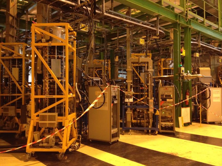

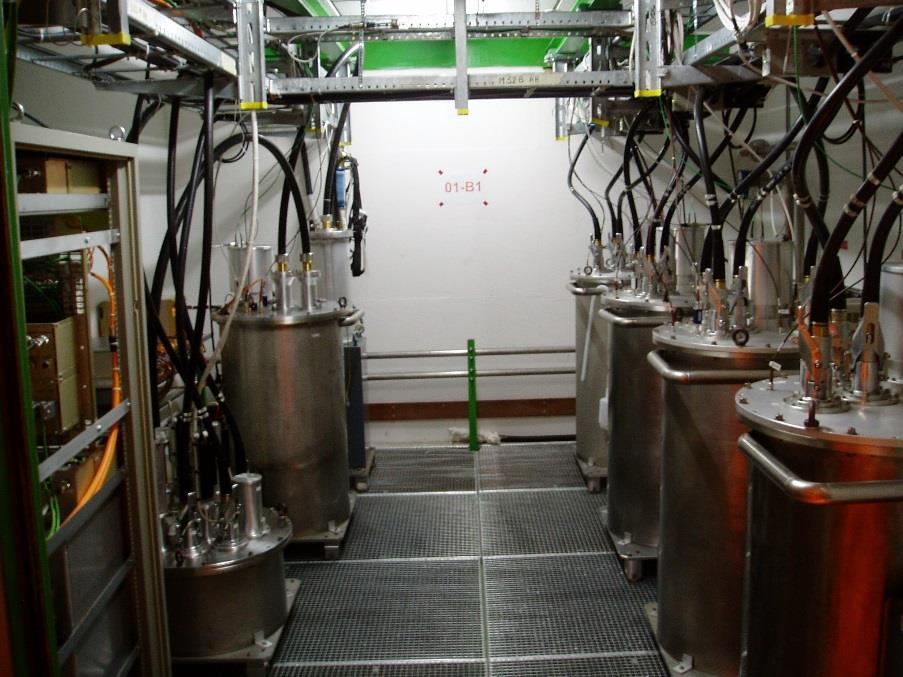
21 LHC RF System

22 LHC Two independent rings: 8 RF cavities per ring all installed at point 4 Klystrons and Cavity Controllers in a cavern ~150 m underground


23 LHC rf system 100kV, 40A (ex-lep) power converters located at the surface Klystron modulators, fast protection systems in four HV bunkers Sixteen 330 kw klystrons + circulators + RF ferrite loads in UX45 WR2300 HH WG distribution system to individual cavities LLRF for Cavity Controllers in two Faraday Cages => Most of RF equipment is not accessible during operation
 Klystron power sweep CW @")
 130 ns group delay (~ 10 MHz BW) CW gain 39 db @ 200 kw,")
24 Klystron CW P out Operating point -1.5dB below saturation Clamped (SWAP) Klystron power sweep MHz P in 1 klystron per cavity 330 kw max (58 kv, 8.4 A) 130 ns group delay (~ 10 MHz BW) CW gain kw, kw In operation 200 kw CW

25 Circulator, RF load, WG - 1 circulator per cavity 330 kw max 60 ns group delay Circulator equipped with temperature control system Affects the Q ext of the cavity -1 RF ferrite load per circulator 330 kw CW RF loads reflection < -28 db - Wave guide system WR2300 HH Length: 15 to 30 meters 25

")
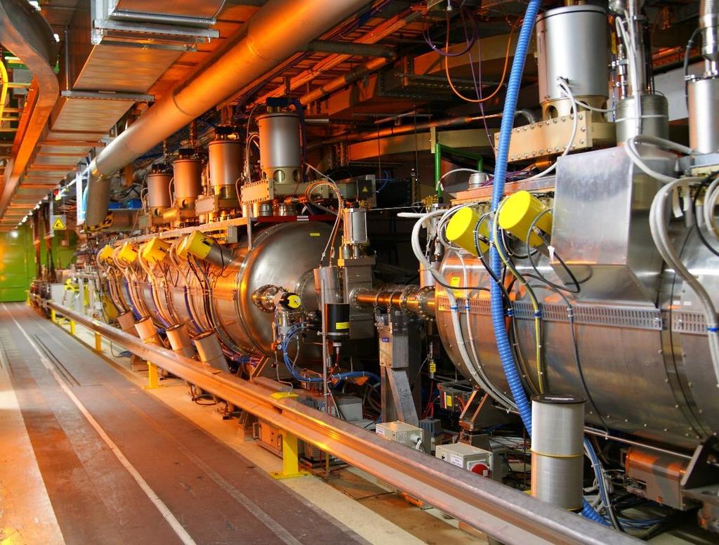
26 Cavities 8 RF cavities per ring at MHz: Super Conducting Standing Wave Cavities, single-cell, R/Q = 45 ohms, 6 MV/m nominal Equipped with movable Main Coupler (20000 < Q L < ) Mechanical Tuner range = 100 khz
27 CLIC a two beam accelerator CAS, Zürich, March 3 rd, 2018 Steffen Döbert, BE-RF
 P 2 3 r c e m c 2 o 3 E 4 r 2 This energy loss must be replaced by the RF system!")
28 The LEP collider LEP (Large Electron Positron collider) was installed in LHC tunnel e+ e- circular collider (27 km) with E cm =200 GeV Problem for any ring: Synchrotron radiation Emitted power: scales with E 4!! and 1/m 03 (much less for heavy particles) P 2 3 r c e m c 2 o 3 E 4 r 2 This energy loss must be replaced by the RF system!! particles lost 3% of their energy each turn!
29 The next lepton collider Solution: LINEAR COLLIDER avoid synchrotron radiation no bending magnets, huge amount of cavities and RF e+ e- damping ring source main linac beam delivery RF in RF out E
30 What is a Linear Collider RF Source RF Source Interaction Point with Detector e + source e + Linac e - Linac e - source High Accelerating Gradient to minimize size and cost in case of CLIC 100 MV/m at 12 GHz ~ 65 MW input peak power per accelerating structure rf pulse length 240 ns

31 Klystron, the conventional RF power source Limited by space charge and power density Relativistic Klystron, Two beam accelerator scheme
 Low charge Main Beam (high collision energy) High power for high")

32 CLIC two beam scheme Two beam acceleration scheme: High charge Drive Beam (low energy) Low charge Main Beam (high collision energy) High power for high gradient of >100 MV/m CLIC TUNNEL CROSS-SECTION Drive beam A, 240 ns from 2.4 GeV to 240 MeV 12 GHz Main beam 1.2 A, 160 ns from 9 GeV to 1.5 TeV 4.5 m diameter

33 600 klystrons 20MW, 139 us CLIC Layout at 3 TeV Drive Beam Generation Complex 600 klystrons 20MW, 139 us Main Beam Generation Complex 33

34 Drive Beam CLIC power source New CLIC layout 380 GeV


 e- SIDE LHC e+ SIDE")
35 CDR tunnel layout e+ INJECTION DESCENT TUNNEL e- INJECTION DESCENT TUNNEL COMBINER RINGS DRIVE BEAM INJECTOR DRIVE BEAM LOOPS 100m BYPASS TUNNEL INTERACTION REGION MAIN BEAM INJECTOR DAMPING RINGS 1km DRIVE BEAM DUMPS TURN AROUND Limestones Moraines Molasse Sands and gravels INJECTION TUNNEL CLIC SCHEMATIC (not to scale) e- SIDE LHC e+ SIDE FRANCE SWITZERLAND
36 CLIC Drive Beam a relativistic klystron CAS, Zürich, March 3 rd, 2018 Steffen Döbert, BE-RF
37 CLIC Drive Beam A 5 TW klystron? Beam current: Beam energy: Pulse Length: Repetition Rate: Average Beam Power: Conversion efficiency: 101 A 2.4 GeV 240 ns one drive beam 50 Hz 3 MW / 70 MW full drive beam 81 % / 44% total Peak power at 12 GHz: 202 GW / 4.8 TW Length: ~ 30 km
 600 Klystrons Low frequency")

38 Drive Beam, an efficient power source Conventional power source (klystrons) inefficient Extract RF power at 12 GHz from an intense e- drive beam Generate efficiently long pulse and compress it (in power + frequency) 600 Klystrons Low frequency High efficiency Power stored in electron beam Power extracted from beam in resonant structures Accelerating Structures High Frequency High field Long RF Pulses Electron beam manipulation Power compression Frequency multiplication Short RF Pulses
39 CLIC Drive Beam generation Drive Beam Accelerator efficient acceleration in fully loaded linac Delay Loop 2 gap creation, pulse compression & frequency multiplication Combiner Ring 4 RF Transverse Deflectors Combiner Ring 3 pulse compression & frequency multiplication pulse compression & frequency multiplication CLIC RF POWER SOURCE LAYOUT Drive Beam Decelerator Section (24 in total) Power Extraction Drive beam time structure - initial Drive beam time structure - final 240 ns 240 ns 5.1 ms 140 ms train length sub-pulses 4.2 A GeV - 60 cm between bunches 24 pulses 100 A 2.5 cm between bunches
40 Lemmings Drive Beam

41 CLIC Test Facility (CTF3)


42 CLIC Test Facility (CTF3) DELAY LOOP COMBINER RING CLEX DRIVE BEAM LINAC TBL Two Beam Module


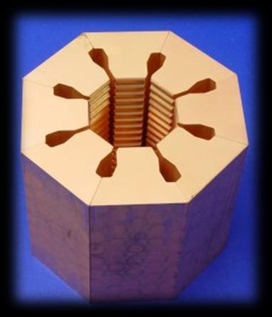
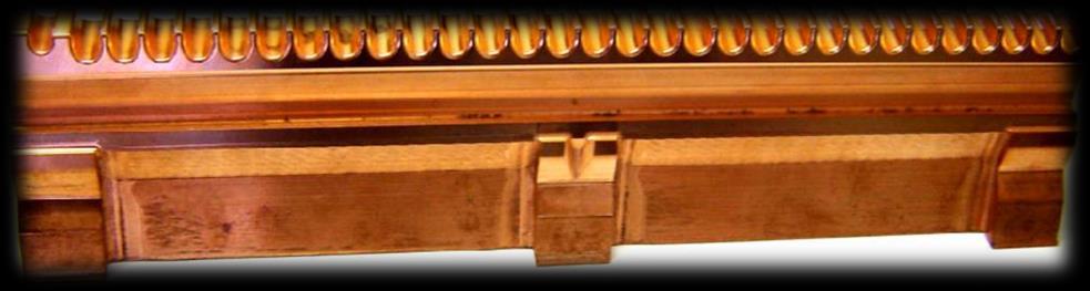
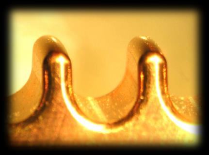
43 Drive Beam Generation Full beam loading acceleration 95.3% RF to beam efficiency RF pulse at structure input 10 m RF pulse at output RF in No RF to load damping slot SiC load High beam current short structure low Ohmic losses Most RF power to beam

44 Delay Loop Double repetition frequency and current Parts of bunch train delayed in loop RF deflector combines the bunches P 0, 0 P 0, 0 Transverse RF Deflector, 0 Deflecting Field 2 P 0, 2 0


45 Delay Loop, with beam CT.BPM A A CT.BPM A
46 Combiner Ring
 Beam Current 0.")
47 Proof of Principle CTF3 - PRELIMINARY PHASE Successful low-charge demonstration of electron pulse combination and bunch frequency multiplication by up to factor 5 Streak camera image of beam time structure evolution 1 st turn streak camera measurement RF deflectors 333 ps 2 nd 3 rd Beam time structure in linac Bunch spacing 333 ps 4 th 420 ns (ring revolution time) Beam Current 0.3 A 5 th turn 66 ps Beam Current 1.5 A Bunch spacing 66 ps Beam structure after combination time

48 CTF3 results Produced high-current drive beam bunched at 12 GHz 3 GHz Arrival time stabilised to 50 fs x2 x3 12 GHz 28A

49 Test Beam Line in CLEX A decelerator experiment periodically corrugated structure with low impedance (big a/λ)

50 Deceleration results Beam Energy (MeV) Prediction from rf power Prediction from beam current Segmented dump measurement Minimum energy 10% threshold: 65.8 MeV 51 % deceleration TBL: P 0 =71.5 MeV/c time (ns) Power produced (90 MW/PETS) fully consistent with drive beam current (24 A) and measured deceleration Total: 1.3 GW of 12 GHz peak power! time (ns) P/P (%) 0 P =76.33 MeV/c, P =6.798% I Beam (A) 3 2 1
 90 80 70 60 50 40 30 20 10 0 120 140 160 180 200 220 240 260 Time (ns) 50 100 150 200 250 300 350 Time")
51 30 GHz Power Production in CTF3 Gradient (MV/m) MW, 70 ns 25 MW, 300 ns Gradient (MV/m) Time (ns) Time (ns)


52 Two beam acceleration Demonstrated two-beam acceleration 31 MeV = 145 MV/m
53 Quest for efficiency CAS, Zürich, March 3 rd, 2018 Steffen Döbert, BE-RF


54 Why does energy efficiency matter? I hope no need to convince any body Does it matter for accelerators? Big interest in society, we should set an example and show that R&D can help We can save some money! Energy consumption T CO 2
: 1.")

: 30 GWh 1 run of cloth washing")


55 Orders of magnitude 1d cyclist Tour de France (4h x 300W): 1.2 kwh 1d Wind Power Station (avg): 12 MWh generation consumption storage 1d nucl. Pow. Plant (e.g. Leibstadt, CH): 30 GWh 1 run of cloth washing machine: kwh 1d SwissLightSource 2.4 GeV,0.4 A: 82 MWh 1d CLIC Linear 3 TeV c.m. 14 GWh Car battery (60 Ah): 0.72 kwh ITER superconducting coil: 12.5 MWh all German storage hydropower: 40 GWh wind-power, 3 MW peak ITER car battery cyclist, 300 W SLS, 3.5 MW nucl. plant 1.3 GW hydro storage CLIC, 580 MW Accelerators are in the range were they become relevant for society and public discussion. Desired turn to renewables is an enormous task; storage is the problem, not production! Fluctuations of energy availability, depending on time and weather, will be large! M. Seidel/PSI


56 Average RF power needs FCC-ee: CW, 400 MHz/0.8 GHz, P RF,total = 110 MW CLIC: Pulsed, 1 GHz, P RF,total = 180 MW Pulsed, 0.7 GHz,92 MW

: 10 13")
: 5 10 8 s 1 @ 30 MeV c")

57 Electricity ggrid ca. 10 MW Example: PSI 10 MW RF Systems 4.1 MW Beam on targets 1.3 MW Neutrons (per beam line): s 10 ev 20 uw Muons (u + per beam line): s 30 MeV c 300 uw Magnets 2.6 MW aux. Systems Instruments 3.3 MW cryogenics reject heat to river, to air M. Seidel/PSI
58 Example FCC-tt : orders of magnitude Note: largest impact by RF power generation Grid to DC: 90% 90% RF power generation! heat 70% RF distribution! heat losses in cavities 95% heat 100% RF to beam Eventually, all is converted to waste heat! Grid: 165 MW Modulator 150 MW RF klystron 105 MW RF to cavities: 100 MW RF available: 100 MW beam: 100 MW Synchrotron radiation: 100 MW Figure of merit: physics results per kwh! dynamic loss K (not to scale) Cryo input 39 MW Cryo for dynamic losses: COP x 250 kw=33 MW heat P. Lebrun Cryo for static losses: 6 MW
59 Example CLIC Drive Beam Klystron development CAS, Zürich, March 3 rd, 2018 Steffen Döbert, BE-RF
60 3 TeV CLIC (CDR): CLIC Drive Beam requirements 1230 klystrons, 20 MW, 150 ms, 50 Hz GW peak power, 184 MW average 0.05 º phase jitter, 0.2% amplitude 380 GeV < 500 klystrons and factor 3 less in average power Main energy consumer in CLIC (~50 % for 3 TeV)
61 CLIC efficiency challenge Example 3 TeV (CDR): CLIC Drive Beam requirements Total wall plug power for rf system: 255 MW Efficiencies: Ƞ mod =0.89 Ƞ kly =0.7 Ƞ RF-DB =0.89 Ƞ Pets =0.98 Ƞ Decel =0.81 Ƞ RF-MB =0.25 Final Main beam power: 28 MW Ƞ tot =0.11 Each percentage counts!
62 Klystron parameters PARAMETER VALUE UNITS RF Frequency Bandwidth at -1dB RF Power: Peak Power Average Power RF Pulse width (at -3dB) HV pulse width (at full width half height) Repetition Rate High Voltage applied to the cathode Tolerable peak reverse voltage Efficiency at peak power RF gain at peak power Perveance Stability of RF output signal at nominal working point: RF phase ripple [*] RF amplitude ripple Pulse failures (arcs etc.) during 14 hour test period Matching load, fundamental and 2 nd harmonic Average radiation at0.1m distance from klystron Output waveguide type, tbd, 180 tbd tbd, > 48 tbd ±1 (max) ±1 (max) < 1-2 tbd < 1 WR975 MHz MHz MW kw μs μs Hz kv kv % db μa/v 1.5 RF deg % VSWR μsv/h 2-3 bar


63 Thales TH beam multi beam klystrons, 153 kv, 76 % efficiency calculated Design approved, delivered November 2017 Efficiency > 73% measured during test


64 Toshiba E37503 factory test 6 beam MBK Test results: f= 999,5 MHz P max = 21 MW P L = 150 ms V= kv I= 180 A = 71.5 % G= 2.83 ma/v 3/2 Gain = 53.9 db Tests done at 25 Hz and double HV pulse length, nominal 50 Hz Stable operation over a wide range of parameters
65 Toshiba E37503 factory test Wide power range with high efficiency
66 CLIC Klystron modulators main specs Pulsed voltage V kn 180 kv Peak nominal power V kn P out 29 MW Rise/fall times t rise 3 μs Flat-top length t flat 140 μs Rep. rate Rep r 50 Hz Pulse repeatability PPR ppm Voltage [V] 1300 modulators synchronously operated t rise 29 MW x 1300 klystrons = 38GW of pulsed power! V ovs ideal pulse t set t flat t fall T rep FTS CLIC modulators R&D real pulse t reset V uns Time [s] Hot R&D topics: Distribution grid layout optimization Active compensation of power fluctuation (new converters topologies) High efficiency, high bandwidth, high repeatable power electronics HV fast pulse transformers design Highly repeatable HV measurements Redundancy, modularity, availability X X X X X X X X EDF, 400kV X X X X X X X X X X X X X X X X X X X X X X X X X X X Klystron modulators 1300 klystron modulators 2 Km in length HV/MV transformers X X X X X MV bus bars MV/LV transformers LV bus bars AC/DC converters DC bus bars
! Pulse stability better than 0.1 %!")
 Optimal grid layout for power distribution proposed")
67 Klystron modulator R&D CERN-ETHZ collaboration for design & delivery of a CLIC s Drive Beam klystron modulator Modulator installed, tested and ready for commissioning with klystron in building 112 World première for precise 180 kv 30 MW pulse with 3µs rise/fall times & a long flat top (150µs)! Pulse stability better than 0.1 %! Collaboration with ETHZ successfully ended CERN-ETHZ Modulator 180 kv split-core pulse transformer Pulse transformer tank 4 years of R&D studies achievements: Feasibility to create voltage pulse verified Solutions found to decouple 39 GW of pulsed power from electrical grid Optimal number of powering sectors found (For civil engineering) Optimal grid layout for power distribution proposed Proposal of a new very high repeatable / precise measuring system for high voltage pulses Discovery of excellent R&D partners in Canada, UK, Italy, & Switzerland!
68 State of the art Commercial MBK (low perveance) tubes with high efficiency. Klystron efficiency vs. perveance

 Igor")
69 Bunch saturation issues. Example of the fully saturated bunch in COM tube (Tesla 2D code) Igor Syratchev
70 End Thanks for your interest Stolen slides from: F. Tecker, E. Jensen, R. Carter, S. Stapnes, R. Corsini, I. Syratchev, M. Seidel Future Questions:
71 What else? Operation, Reliability, Stability, Integration with LLRF and Acceleration Equipment CAS, Zürich, March 3 rd, 2018 Steffen Döbert, BE-RF
72 Veto RF Switch RF power distribution & critical interlocks Klystron Wattcher LO Wattcher HI (fast) Circulator Load Arc detect or Main Power Coupler (ceramic window) Cavity MC Vacuum HOM Power HOM coupler HOM Temperature Beam Helium pressure (cavity quench) Helium level (Cryo OK)
 RF interlocks (Trips 1")
73 RF and HV Interlock chains HV interlocks Brings down complete module (4 Klystrons) RF interlocks (Trips 1 Klystron)

74 10/3 12/3 14/3 16/3 18/3 20/3 22/3 24/3 26/3 28/3 30/3 1/4 3/4 5/4 7/4 9/4 11/4 13/4 15/4 17/4 19/4 21/4 23/4 25/4 27/4 29/4 1/5 3/5 faults/day max beam Reliability and performance I cat out of range Scanio communication Body thermal power Main Coupler blowers He tank Pressure Crowbar not ready Klystron filament Kly Vac Crowbar Arc detected Max Beam E E E E E E E E E+10 time L. Arnaudon RF system consists of about 1000 interlocks Long periods (>>days), without RF trips. The RF system is very reliable with the present beam conditions, efforts will continue to prepare for the higher intensity runs
75 Operational Experience RF System runs well -- few trips per year (4 th dump cause in numbers, 10 th in downtime) still need for increase of reliability Klystron Exchange for age profile exchanged 1 for multipactor, 1 for gun short 1 dead due to collector design issue (ongoing collector boiler replacement) Tetrode Replacement 5 dead per year Arc Detector Deployment Oil Re-conditioning R Module replacement Courtesy Alick Macpherson 75
76 Spare slides CAS, Zürich, March 3 rd, 2018 Steffen Döbert, BE-RF
77 Accelerating gradient? We need higher gradient per unit length (cost) 10 MV/m MV/m: Routinely achieved (LIL) 50 MV/m: Super-conducting limit 100 MV/m MV/m: Normal-conducting linear collider > 1 GV/m Future: Plasma/Laser/Wakefield acceleration


78 Why very high frequency? LEP-Cavity 350 MHz CLIC-Cavity 30 GHz


79 Klystron modulator R&D Modulator schematic layout (thesis. S. Blume)
, < 500 MHz, 600 W (Anode removed) RS")
, < 260")
80 Tetrodes control grid screen grid Ra cathode anode (plate) +Ua potential Ia=0 Ua Ia max Ug2 Ug1 4CX250B (Eimac/CPI), < 500 MHz, 600 W (Anode removed) RS 1084 CJ (ex Siemens, now Thales), < 30 MHz, 75 kw Takes advantage from mobility of electrons in vacuum YL1520 (ex Philips, now Richardson), < 260 MHz, 25 kw


81 Klystron Test Stand Location: CERN Bldg: 112
 Lucie Linssen, March 5th 2015")
82 drive beam Recently installed 2-beam acceleration module in CTF3 (according 82 to latest CLIC design) Lucie Linssen, March 5th 2015 main beam
RF Power Generation II
 RF Power Generation II Klystrons, Magnetrons and Gyrotrons Professor R.G. Carter Engineering Department, Lancaster University, U.K. and The Cockcroft Institute of Accelerator Science and Technology Scope
Detailed Design Report
 Detailed Design Report Chapter 4 MAX IV Injector 4.6. Acceleration MAX IV Facility CHAPTER 4.6. ACCELERATION 1(10) 4.6. Acceleration 4.6. Acceleration...2 4.6.1. RF Units... 2 4.6.2. Accelerator Units...
INFN School on Electron Accelerators. RF Power Sources and Distribution
 INFN School on Electron Accelerators 12-14 September 2007, INFN Sezione di Pisa Lecture 7b RF Power Sources and Distribution Carlo Pagani University of Milano INFN Milano-LASA & GDE The ILC Double Tunnel
Status of CTF3. G.Geschonke CERN, AB
 Status of CTF3 G.Geschonke CERN, AB CTF3 layout CTF3 - Test of Drive Beam Generation, Acceleration & RF Multiplication by a factor 10 Drive Beam Injector ~ 50 m 3.5 A - 2100 b of 2.33 nc 150 MeV - 1.4
A HIGH POWER LONG PULSE HIGH EFFICIENCY MULTI BEAM KLYSTRON
 A HIGH POWER LONG PULSE HIGH EFFICIENCY MULTI BEAM KLYSTRON A.Beunas and G. Faillon Thales Electron Devices, Vélizy, France S. Choroba DESY, Hamburg, Germany Abstract THALES ELECTRON DEVICES has developed
CLIC Feasibility Demonstration at CTF3
 CLIC Feasibility Demonstration at CTF3 Roger Ruber Uppsala University, Sweden, for the CLIC/CTF3 Collaboration http://cern.ch/clic-study LINAC 10 MO303 13 Sep 2010 The Key to CLIC Efficiency NC Linac for
Towards an X-Band Power Source at CERN and a European Structure Test Facility
 Towards an X-Band Power Source at CERN and a European Structure Test Facility Erk Jensen and Gerry McMomagle CERN The X-Band Accelerating Structure Design and Test-Program Workshop Day 2: Structure Testing
IOT OPERATIONAL EXPERIENCE ON ALICE AND EMMA AT DARESBURY LABORATORY
 IOT OPERATIONAL EXPERIENCE ON ALICE AND EMMA AT DARESBURY LABORATORY A. Wheelhouse ASTeC, STFC Daresbury Laboratory ESLS XVIII Workshop, ELLETRA 25 th 26 th November 2010 Contents Brief Description ALICE
RF plans for ESS. Morten Jensen. ESLS-RF 2013 Berlin
 RF plans for ESS Morten Jensen ESLS-RF 2013 Berlin Overview The European Spallation Source (ESS) will house the most powerful proton linac ever built. The average beam power will be 5 MW which is five
XFEL High Power RF System Recent Developments
 XFEL High Power RF System Recent Developments for the XFEL RF Group Outline XFEL RF System Requirements Overview Basic Layout RF System Main Components Multibeam Klystrons Modulator RF Waveguide Distribution
PoS(EPS-HEP2015)525. The RF system for FCC-ee. A. Butterworth CERN 1211 Geneva 23, Switzerland
525. The RF system for FCC-ee. A. Butterworth CERN 1211 Geneva 23, Switzerland") CERN 1211 Geneva 23, Switzerland E-mail: andrew.butterworth@cern.ch O. Brunner CERN 1211 Geneva 23, Switzerland E-mail: olivier.brunner@cern.ch R. Calaga CERN 1211 Geneva 23, Switzerland E-mail: rama.calaga@cern.ch
CERN 1211 Geneva 23, Switzerland E-mail: andrew.butterworth@cern.ch O. Brunner CERN 1211 Geneva 23, Switzerland E-mail: olivier.brunner@cern.ch R. Calaga CERN 1211 Geneva 23, Switzerland E-mail: rama.calaga@cern.ch
STATUS AND FUTURE PROSPECTS OF CLIC
 STATUS AND FUTURE PROSPECTS OF CLIC S. Döbert, for the CLIC/CTF3 collaboration, CERN, Geneva, Switzerland Abstract The Compact Linear Collider (CLIC) is studied by a growing international collaboration.
RF considerations for SwissFEL
 RF considerations for H. Fitze in behalf of the PSI RF group Workshop on Compact X-Ray Free Electron Lasers 19.-21. July 2010, Shanghai Agenda Introduction RF-Gun Development C-band development Summary
Pulsed Klystrons for Next Generation Neutron Sources Edward L. Eisen - CPI, Inc. Palo Alto, CA, USA
 Pulsed Klystrons for Next Generation Neutron Sources Edward L. Eisen - CPI, Inc. Palo Alto, CA, USA Abstract The U.S. Department of Energy (DOE) Office of Science has funded the construction of a new accelerator-based
DESIGN AND PERFORMANCE OF L-BAND AND S-BAND MULTI BEAM KLYSTRONS
 DESIGN AND PERFORMANCE OF L-BAND AND S-BAND MULTI BEAM KLYSTRONS Y. H. Chin, KEK, Tsukuba, Japan. Abstract Recently, there has been a rising international interest in multi-beam klystrons (MBK) in the
ILC-LNF TECHNICAL NOTE
 IL-LNF EHNIAL NOE Divisione Acceleratori Frascati, July 4, 2006 Note: IL-LNF-001 RF SYSEM FOR HE IL DAMPING RINGS R. Boni, INFN-LNF, Frascati, Italy G. avallari, ERN, Geneva, Switzerland Introduction For
4.4 Injector Linear Accelerator
 4.4 Injector Linear Accelerator 100 MeV S-band linear accelerator based on the components already built for the S-Band Linear Collider Test Facility at DESY [1, 2] will be used as an injector for the CANDLE
RF Solutions for Science.
 RF Solutions for Science www.thalesgroup.com State-of-the-art RF sources for your scientific needs High-power klystrons HIGH KLYSTRONS WITH RF LONG PULSE above 50 μs Thales has been one of the leading
Current status of XFEL/SPring-8 project and SCSS test accelerator
 Current status of XFEL/SPring-8 project and SCSS test accelerator Takahiro Inagaki for XFEL project in SPring-8 inagaki@spring8.or.jp Outline (1) Introduction (2) Key technology for compactness (3) Key
The FLASH objective: SASE between 60 and 13 nm
 Injector beam control studies winter 2006/07 talk from E. Vogel on work performed by W. Cichalewski, C. Gerth, W. Jalmuzna,W. Koprek, F. Löhl, D. Noelle, P. Pucyk, H. Schlarb, T. Traber, E. Vogel, FLASH
RF Upgrades & Experience At JLab. Rick Nelson
 RF Upgrades & Experience At JLab Rick Nelson Outline Background: CEBAF / Jefferson Lab History, upgrade requirements & decisions Progress & problems along the way Present status Future directions & concerns
Next Linear Collider. The 8-Pack Project. 8-Pack Project. Four 50 MW XL4 X-band klystrons installed on the 8-Pack
 The Four 50 MW XL4 X-band klystrons installed on the 8-Pack The Demonstrate an NLC power source Two Phases: 8-Pack Phase-1 (current): Multi-moded SLED II power compression Produce NLC baseline power: 475
Evaluation of Performance, Reliability, and Risk for High Peak Power RF Sources from S-band through X-band for Advanced Accelerator Applications
 Evaluation of Performance, Reliability, and Risk for High Peak Power RF Sources from S-band through X-band for Advanced Accelerator Applications Michael V. Fazio C. Adolphsen, A. Jensen, C. Pearson, D.
Introduction: CW SRF linac types, requirements and challenges High power RF system architecture
 RF systems for CW SRF linacs S. Belomestnykh Cornell University Laboratory for Elementary-Particle Physics LINAC08, Victoria, Canada October 1, 2008 Outline L band Introduction: CW SRF linac types, requirements
Status of BESSY II and berlinpro. Wolfgang Anders. Helmholtz-Zentrum Berlin for Materials and Energy (HZB) 20th ESLS-RF Meeting
 20th ESLS-RF Meeting") Status of BESSY II and berlinpro Wolfgang Anders Helmholtz-Zentrum Berlin for Materials and Energy (HZB) 20th ESLS-RF Meeting 16.-17.11.2016 at PSI Outline BESSY II Problems with circulators Landau cavity
Status of BESSY II and berlinpro Wolfgang Anders Helmholtz-Zentrum Berlin for Materials and Energy (HZB) 20th ESLS-RF Meeting 16.-17.11.2016 at PSI Outline BESSY II Problems with circulators Landau cavity
3 cerl. 3-1 cerl Overview. 3-2 High-brightness DC Photocathode Gun and Gun Test Beamline
 3 cerl 3-1 cerl Overview As described before, the aim of the cerl in the R&D program includes the development of critical components for the ERL, as well as the construction of a test accelerator. The
Experience with the Cornell ERL Injector SRF Cryomodule during High Beam Current Operation
 Experience with the Cornell ERL Injector SRF Cryomodule during High Beam Current Operation Matthias Liepe Assistant Professor of Physics Cornell University Experience with the Cornell ERL Injector SRF
LCLS RF Reference and Control R. Akre Last Update Sector 0 RF and Timing Systems
 LCLS RF Reference and Control R. Akre Last Update 5-19-04 Sector 0 RF and Timing Systems The reference system for the RF and timing starts at the 476MHz Master Oscillator, figure 1. Figure 1. Front end
Spear3 RF System Sam Park 11/06/2003. Spear3 RF System. High Power Components Operation and Control. RF Requirement.
 Spear3 RF System RF Requirement Overall System High Power Components Operation and Control SPEAR 3 History 1996 Low emittance lattices explored 1996 SPEAR 3 proposed 11/97 SPEAR 3 design study team formed
Lecture 17 Microwave Tubes: Part I
 Basic Building Blocks of Microwave Engineering Prof. Amitabha Bhattacharya Department of Electronics and Communication Engineering Indian Institute of Technology, Kharagpur Lecture 17 Microwave Tubes:
Present Status and Future Upgrade of KEKB Injector Linac
 Present Status and Future Upgrade of KEKB Injector Linac Kazuro Furukawa, for e /e + Linac Group Present Status Upgrade in the Near Future R&D towards SuperKEKB 1 Machine Features Present Status and Future
18 GHz, 2.2 kw KLYSTRON GENERATOR GKP 24KP 18GHz WR62 3x400V
 18 GHz, 2.2 kw KLYSTRON GENERATOR GKP 24KP 18GHz WR62 3x400V With its characteristics of power stability whatever the load, very fast response time when pulsed (via external modulated signal), low ripple,
Diamond RF Status (RF Activities at Daresbury) Mike Dykes
 Mike Dykes") Diamond RF Status (RF Activities at Daresbury) Mike Dykes ASTeC What is it? What does it do? Diamond Status Linac Booster RF Storage Ring RF Summary Content ASTeC ASTeC was formed in 2001 as a centre of
Diamond RF Status (RF Activities at Daresbury) Mike Dykes ASTeC What is it? What does it do? Diamond Status Linac Booster RF Storage Ring RF Summary Content ASTeC ASTeC was formed in 2001 as a centre of
North Damping Ring RF
 North Damping Ring RF North Damping Ring RF Outline Overview High Power RF HVPS Klystron & Klystron EPICS controls Cavities & Cavity Feedback SCP diagnostics & displays FACET-specific LLRF LLRF distribution
KEKB INJECTOR LINAC AND UPGRADE FOR SUPERKEKB
 KEKB INJECTOR LINAC AND UPGRADE FOR SUPERKEKB S. Michizono for the KEK electron/positron Injector Linac and the Linac Commissioning Group KEK KEKB injector linac Brief history of the KEK electron linac
PEP II Design Outline
 PEP II Design Outline Balša Terzić Jefferson Lab Collider Review Retreat, February 24, 2010 Outline General Information Parameter list (and evolution), initial design, upgrades Collider Ring Layout, insertions,
The Elettra Storage Ring and Top-Up Operation
 The Elettra Storage Ring and Top-Up Operation Emanuel Karantzoulis Past and Present Configurations 1994-2007 From 2008 5000 hours /year to the users 2010: Operations transition year Decay mode, 2 GeV (340mA)
!"!3
 Abstract A single-mode 500 MHz superconducting cavity cryomodule has been developed at Cornell for the electronpositron collider/synchrotron light source CESR. The Cornell B-cell cavity belongs to the
PULSED POWER FOR FUTURE LINEAR ACCELERATORS
 PULSED POWER FOR FUTURE LINEAR ACCELERATORS Peter D. Pearce High-energy accelerators High-energy accelerators enable us to collide particle beams together and create conditions believed to be similar to
DEVELOPMENT OF A 10 MW SHEET BEAM KLYSTRON FOR THE ILC*
 DEVELOPMENT OF A 10 MW SHEET BEAM KLYSTRON FOR THE ILC* D. Sprehn, E. Jongewaard, A. Haase, A. Jensen, D. Martin, SLAC National Accelerator Laboratory, Menlo Park, CA 94020, U.S.A. A. Burke, SAIC, San
14 GHz, 2.2 kw KLYSTRON GENERATOR GKP 22KP 14GHz WR62 3x400V
 14 GHz, 2.2 kw KLYSTRON GENERATOR GKP 22KP 14GHz WR62 3x400V With its characteristics of power stability independent of the load, very fast response time when pulsed (via external modulated signal), low
SLS RF operation report 2003
 SLS RF operation report 2003 M. Pedrozzi, Jean-Yves Raguin Paul Scherrer Institute, 5232 Villigen PSI, Switzerland SUMMARY LINAC report SR Superconducting Third Harmonic system report SR 500 MHz system
STATUS OF THE SWISSFEL C-BAND LINEAR ACCELERATOR
 Proceedings of FEL213, New York, NY, USA STATUS OF THE SWISSFEL C-BAND LINEAR ACCELERATOR F. Loehl, J. Alex, H. Blumer, M. Bopp, H. Braun, A. Citterio, U. Ellenberger, H. Fitze, H. Joehri, T. Kleeb, L.
THE NEXT LINEAR COLLIDER TEST ACCELERATOR: STATUS AND RESULTS * Abstract
 SLAC PUB 7246 June 996 THE NEXT LINEAR COLLIDER TEST ACCELERATOR: STATUS AND RESULTS * Ronald D. Ruth, SLAC, Stanford, CA, USA Abstract At SLAC, we are pursuing the design of a Next Linear Collider (NLC)
Linac upgrade plan using a C-band system for SuperKEKB
 Linac upgrade plan using a C-band system for SuperKEKB S. Fukuda, M. Akemono, M. Ikeda, T. Oogoe, T. Ohsawa, Y. Ogawa, K. Kakihara, H. Katagiri, T. Kamitani, M. Sato, T. Shidara, A. Shirakawa, T. Sugimura,
45 MW, 22.8 GHz Second-Harmonic Multiplier for High-Gradient Tests*
 US High Gradient Research Collaboration Workshop. SLAC, May 23-25, 2007 45 MW, 22.8 GHz Second-Harmonic Multiplier for High-Gradient Tests* V.P. Yakovlev 1, S.Yu. Kazakov 1,2, and J.L. Hirshfield 1,3 1
X-Band Klystron Development at
 X-Band Klystron Development at SLAC Slide 1 The Beginning X-band klystron work began at SLAC in the mid to late 80 s to develop high frequency (4x SLAC s-band), high power RF sources for the linear collider
CLIC FEASIBILITY DEMONSTRATION AT CTF3
 CLIC FEASIBILITY DEMONSTRATION AT CTF3 Abstract The CLIC/CTF3 collaboration is studying the feasibility of a multi-tev electron-positron collider, the so-called CLIC: Compact LInear Collider. The idea
Dark current and multipacting trajectories simulations for the RF Photo Gun at PITZ
 Dark current and multipacting trajectories simulations for the RF Photo Gun at PITZ Introduction The PITZ RF Photo Gun Field simulations Dark current simulations Multipacting simulations Summary Igor Isaev
Digital BPMs and Orbit Feedback Systems
 Digital BPMs and Orbit Feedback Systems, M. Böge, M. Dehler, B. Keil, P. Pollet, V. Schlott Outline stability requirements at SLS storage ring digital beam position monitors (DBPM) SLS global fast orbit
ANKA RF System - Upgrade Strategies
 ANKA RF System - Upgrade Strategies Vitali Judin ANKA Synchrotron Radiation Facility 2014-09 - 17 KIT University of the State Baden-Wuerttemberg and National Laboratory of the Helmholtz Association www.kit.edu
SRS and ERLP developments. Andrew moss
 SRS and ERLP developments Andrew moss Contents SRS Status Latest news Major faults Status Energy Recovery Linac Prototype Latest news Status of the RF system Status of the cryogenic system SRS Status Machine
LHC Beam Instrumentation Further Discussion
 LHC Beam Instrumentation Further Discussion LHC Machine Advisory Committee 9 th December 2005 Rhodri Jones (CERN AB/BDI) Possible Discussion Topics Open Questions Tune measurement base band tune & 50Hz
9th ESLS RF Meeting September ALBA RF System. F. Perez. RF System 1/20
 ALBA RF System F. Perez RF System 1/20 ALBA Synchrotron Light Source in Barcelona (Spain) 3 GeV accelerator 30 beamlines (7 on day one) 50-50 Spanish Government Catalan Government First beam for users
The LEP Superconducting RF System
 The LEP Superconducting RF System K. Hübner* for the LEP RF Group CERN The basic components and the layout of the LEP rf system for the year 2000 are presented. The superconducting system consisted of
Development of klystrons with ultimately high - 90% RF power production efficiency
 Development of klystrons with ultimately high - 90% RF power production efficiency A. Baikov (MUFA), I. Syratchev (CERN), C. Lingwood, D. Constable (Lancaster University) Introduction FCC has high power
SUMMARY OF THE ILC R&D AND DESIGN
 SUMMARY OF THE ILC R&D AND DESIGN B. C. Barish, California Institute of Technology, USA Abstract The International Linear Collider (ILC) is a linear electron-positron collider based on 1.3 GHz superconducting
KARA and FLUTE RF Overview/status
 KARA and FLUTE RF Overview/status Nigel Smale on behalf of IBPT and LAS teams Laboratory for Applications of Synchrotron radiation (LAS) Institute for Beam Physics and Technology (IBPT) KARA KIT The Research
The TESLA RF System. S. Choroba. for the TESLA Collaboration. DESY Notkestr. 85, D Hamburg, Germany
 The TESLA RF System S. Choroba for the TESLA Collaboration DESY Notkestr. 85, D-22603 Hamburg, Germany Abstract. The TESLA project proposed by the TESLA collaboration in 2001 is a 500 to 800GeV e+/e- linear
The PEFP 20-MeV Proton Linear Accelerator
 Journal of the Korean Physical Society, Vol. 52, No. 3, March 2008, pp. 721726 Review Articles The PEFP 20-MeV Proton Linear Accelerator Y. S. Cho, H. J. Kwon, J. H. Jang, H. S. Kim, K. T. Seol, D. I.
The ESS Accelerator. For Norwegian Industry and Research. Oslo, 24 Sept Håkan Danared Deputy Head Accelerator Division Group Leader Beam Physics
 The ESS Accelerator For Norwegian Industry and Research Oslo, 24 Sept 2013 Håkan Danared Deputy Head Accelerator Division Group Leader Beam Physics The Hadron Intensity Frontier Courtesy of M. Seidel (PSI)
Karin Rathsman, Håkan Danared and Rihua Zeng. Report from RF Power Source Workshop
 Accelerator Division ESS AD Technical Note ESS/AD/0020 Karin Rathsman, Håkan Danared and Rihua Zeng Report from RF Power Source Workshop 10 July 2011 Report on the RF Power Source Workshop K. Rathsman,
IOT RF Power Sources for Pulsed and CW Linacs
 LINAC 2004 Lübeck, August 16 20, 2004 IOT RF Power Sources H. Bohlen, Y. Li, Bob Tornoe Communications & Power Industries Eimac Division, San Carlos, CA, USA Linac RF source property requirements (not
Design and Simulation of High Power RF Modulated Triode Electron Gun. A. Poursaleh
 Design and Simulation of High Power RF Modulated Triode Electron Gun A. Poursaleh National Academy of Sciences of Armenia, Institute of Radio Physics & Electronics, Yerevan, Armenia poursaleh83@yahoo.com
Development of High Power Vacuum Tubes for Accelerators and Plasma Heating
 Development of High Power Vacuum Tubes for Accelerators and Plasma Heating Vishnu Srivastava Microwave Tubes Division, CSIR-Central Electronics Engineering Research Institute, Pilani-333031, Rajasthan,
Status of RF Power and Acceleration of the MAX IV - LINAC
 Status of RF Power and Acceleration of the MAX IV - LINAC Dionis Kumbaro ESLS RF Workshop 2015 MAX IV Laboratory A National Laboratory for synchrotron radiation at Lunds University 1981 MAX-lab is formed
TITLE PAGE. Title of paper: PUSH-PULL FEL, A NEW ERL CONCEPT Author: Andrew Hutton. Author Affiliation: Jefferson Lab. Requested Proceedings:
 TITLE PAGE Title of paper: PUSH-PULL FEL, A NEW ERL CONCEPT Author: Andrew Hutton Author Affiliation: Jefferson Lab Requested Proceedings: Unique Session ID: Classification Codes: Keywords: Energy Recovery,
J/NLC Progress on R1 and R2 Issues. Chris Adolphsen
 J/NLC Progress on R1 and R2 Issues Chris Adolphsen Charge to the International Linear Collider Technical Review Committee (ILC-TRC) To assess the present technical status of the four LC designs at hand,
Upgrading LHC Luminosity
 1 Upgrading LHC Luminosity 2 Luminosity (cm -2 s -1 ) Present (2011) ~2 x10 33 Beam intensity @ injection (*) Nominal (2015?) 1 x 10 34 1.1 x10 11 Upgraded (2021?) ~5 x10 34 ~2.4 x10 11 (*) protons per
2 Work Package and Work Unit descriptions. 2.8 WP8: RF Systems (R. Ruber, Uppsala)
") 2 Work Package and Work Unit descriptions 2.8 WP8: RF Systems (R. Ruber, Uppsala) The RF systems work package (WP) addresses the design and development of the RF power generation, control and distribution
2 Work Package and Work Unit descriptions 2.8 WP8: RF Systems (R. Ruber, Uppsala) The RF systems work package (WP) addresses the design and development of the RF power generation, control and distribution
A HIGH-POWER SUPERCONDUCTING H - LINAC (SPL) AT CERN
 AT CERN") A HIGH-POWER SUPERCONDUCTING H - LINAC (SPL) AT CERN E. Chiaveri, CERN, Geneva, Switzerland Abstract The conceptual design of a superconducting H - linear accelerator at CERN for a beam energy of 2.2 GeV
A HIGH-POWER SUPERCONDUCTING H - LINAC (SPL) AT CERN E. Chiaveri, CERN, Geneva, Switzerland Abstract The conceptual design of a superconducting H - linear accelerator at CERN for a beam energy of 2.2 GeV
CLIC Feasibility Demonstration at CTF3
 CLIC Feasibility Demonstration at CTF3 Roger Ruber Uppsala University, Sweden, KVI Groningen 20 Sep 2011 The Key to CLIC Efficiency NC Linac for 1.5 TeV/beam accelerating gradient: 100 MV/m RF frequency:
Introduction to CTF3. G.Geschonke CERN / PS
 Introduction to CTF3 G.Geschonke CERN / PS Aim of review: Review the technical solutions are they realistic? Give us technical advice Comment on alternatives Guide our funding bodies: CERN Collaborations
Pulses inside the pulse mode of operation at RF Gun
 Pulses inside the pulse mode of operation at RF Gun V. Vogel, V. Ayvazyan, K. Floettmann, D. Lipka, P. Morozov, H. Schlarb, S. Schreiber FLASH Seminar, DESY March 29, 2011 Contents Why we need a PiPmode
CERN EUROPEAN ORGANIZATION FOR NUCLEAR RESEARCH. A 50 Hz LOW-POWER SOLID-STATE KLYSTRON-MODULATOR
 CERN EUROPEAN ORGANIZATION FOR NUCLEAR REEARCH CTF3 Note 051(Tech.) (IGCT witch) A 50 Hz LOW-POWER OLID-TATE KLYTRON-MODULATOR P. Pearce, L. ermeus, L. hen Abstract A solid-state klystron-modulator has
5 Project Costs and Schedule
 93 5 Project Costs and Schedule 5.1 Overview The cost evaluation for the integrated version of the XFEL with 30 experiments and 35 GeV beam energy as described in the TDR-2001 yielded 673 million EUR for
RF Power Klystrons & 20 Year Look. R. Nelson 7/15/15
 RF Power Klystrons & 20 Year Look R. Nelson 7/15/15 RF Power klystrons 8 x 13 kw klystrons Page 2 Why A klystron? Best (only) choice at the time - 1988 Easy to use: Input (drive), output (to CM), power
LLRF at SSRF. Yubin Zhao
 LLRF at SSRF Yubin Zhao 2017.10.16 contents SSRF RF operation status Proton therapy LLRF Third harmonic cavity LLRF Three LINAC LLRF Hard X FEL LLRF (future project ) Trip statistics of RF system Trip
The basic parameters of the pre-injector are listed in the Table below. 100 MeV
 3.3 The Pre-injector The high design brightness of the SLS requires very high phase space density of the stored electrons, leading to a comparatively short lifetime of the beam in the storage ring. This,
RF upgrade program in LHC injectors and LHC machine
 RF upgrade program in LHC injectors and LHC machine E r k J e n s e n, o n b e h a l f o f B E - RF Many thanks to M. E. Angoletta, O. Brunner, R. Calaga, E. Ciapala, H. Damerau, W. Höfle, E. Montesinos,
Status of SOLARIS. Paweł Borowiec On behalf of Solaris Team
 Status of SOLARIS Paweł Borowiec On behalf of Solaris Team e-mail: pawel.borowiec@uj.edu.pl XX ESLS-RF Meeting, Villingen 16-17.11.2016 Outline 1. Timeline 2. Injector 3. Storage ring 16-17.11.2016 XX
NLC - The Next Linear Collider Project NLC R&D. D. L. Burke. DOE Annual Program Review SLAC April 9-11, 2003
 DOE Annual Program Review SLAC April 9-11, 2003 NLC Activities for the Past Year Accelerator Design centered around ILC-TRC studies. Technology R&D focused on the RF R&D. Modulator, klystron, SLED-II,
Solid State Modulators for X-Band Accelerators
 Solid State Modulators for X-Band Accelerators John Kinross-Wright Diversified Technologies, Inc. Bedford, Massachusetts DTI X-Band Experience Developed and built two completely different NLC-class modulator
RF POWER GENERATION FOR FUTURE LINEAR COLLIDERS* 1. Introduction
 SLAC-PUB-5282 June 1990 (A) RF POWER GENERATION FOR FUTURE LINEAR COLLIDERS* W. R. Fowkes, M. A. Allen, R. S. Callin, G. Caryotakis, K. R. Eppley, K. S. Fant, Z. D. Farkas, J. Feinstein, K. Ko, R. F. Koontz,
RF Power Upgrade at Jefferson Lab
 RF Power Upgrade at Jefferson Lab Rick Nelson*, Andrew Kimber *nelson@jlab.org * Notice: Authored by Jefferson Science Associates, LLC under U.S. DOE Contract No. DE- AC05-06OR23177. The U.S. Government
NEW METHOD FOR KLYSTRON MODELING
 NEW METHOD FOR KLYSTRON MODELING Y. H. Chin, KEK, 1-1 Oho, Tsukuba-shi, Ibaraki-ken, 35, Japan Abstract We have developed a new method for a realistic and more accurate simulation of klystron using the
L-Band RF R&D. SLAC DOE Review June 15 th, Chris Adolphsen SLAC
 L-Band RF R&D SLAC DOE Review June 15 th, 2005 Chris Adolphsen SLAC International Linear Collider (ILC) RF Unit (TESLA TDR Layout) Gradient = 23.4 MV/m Bunch Spacing = 337 ns Fill Time = 420 µs Train Length
Low Level RF for PIP-II. Jonathan Edelen LLRF 2017 Workshop (Barcelona) 16 Oct 2017
 16 Oct 2017") Low Level RF for PIP-II Jonathan Edelen LLRF 2017 Workshop (Barcelona) 16 Oct 2017 PIP-II LLRF Team Fermilab Brian Chase, Edward Cullerton, Joshua Einstein, Jeremiah Holzbauer, Dan Klepec, Yuriy Pischalnikov,
Low Level RF for PIP-II Jonathan Edelen LLRF 2017 Workshop (Barcelona) 16 Oct 2017 PIP-II LLRF Team Fermilab Brian Chase, Edward Cullerton, Joshua Einstein, Jeremiah Holzbauer, Dan Klepec, Yuriy Pischalnikov,
WG2 Group Summary. Chris Adolphsen Terry Garvey Hitoshi Hayano
 WG2 Group Summary Chris Adolphsen Terry Garvey Hitoshi Hayano Linac Options Fest On Thursday afternoon, various experts summarized the linac baseline options. Although hard choices have yet to be made,
NSLS-II RF Systems James Rose, Radio Frequency Group Leader PAC 2011
 NSLS-II RF Systems James Rose, Radio Frequency Group Leader PAC 2011 1 BROOKHAVEN SCIENCE ASSOCIATES Introduction Linac RF cavities and klystrons Booster Cavity-Transmitter Storage Ring 500 MHz SRF cavity
reported by T. Shintake KEK / RIKEN Japan Summary of C-band R&D for Linear Collider at KEK New soft-x-ray FEL Project at RIKEN/SPring-8
 C-band RF System R&D reported by T. Shintake KEK / RIKEN Japan Summary of C-band R&D for Linear Collider at KEK New soft-x-ray FEL Project at RIKEN/SPring-8 Project was funded in 2001 April Material Science
UNIT-3 Part A. 2. What is radio sonde? [ N/D-16]
![UNIT-3 Part A. 2. What is radio sonde? [ N/D-16]](/thumbs/88/116973079.jpg "UNIT-3 Part A. 2. What is radio sonde? [ N/D-16]") UNIT-3 Part A 1. What is CFAR loss? [ N/D-16] Constant false alarm rate (CFAR) is a property of threshold or gain control devices that maintain an approximately constant rate of false target detections
UNIT-3 Part A 1. What is CFAR loss? [ N/D-16] Constant false alarm rate (CFAR) is a property of threshold or gain control devices that maintain an approximately constant rate of false target detections
Final Report. U.S. Department of Energy Grant Number DE-FG02-04ER83916
 Development of a 200 MHz Multiple Beam Klystron Final Report U.S. Department of Energy Grant Number DE-FG02-04ER83916 July 2004 - March 2005 Calabazas Creek Research, Inc. 20937 Comer Drive Saratoga, CA
A SHEET-BEAM KLYSTRON PAPER DESIGN
 SLAC-PUB-8967 A SHEET-BEAM KLYSTRON PAPER DESIGN G. Caryotakis Stanford Linear Accelerator Center, Stanford University, Stanford Ca. 94309 Abstract What may be the first detailed cold test and computer
High Brightness Injector Development and ERL Planning at Cornell. Charlie Sinclair Cornell University Laboratory for Elementary-Particle Physics
 High Brightness Injector Development and ERL Planning at Cornell Charlie Sinclair Cornell University Laboratory for Elementary-Particle Physics June 22, 2006 JLab CASA Seminar 2 Background During 2000-2001,
EPJ Web of Conferences 95,
 EPJ Web of Conferences 95, 04012 (2015) DOI: 10.1051/ epjconf/ 20159504012 C Owned by the authors, published by EDP Sciences, 2015 The ELENA (Extra Low Energy Antiproton) project is a small size (30.4
Design Studies For The LCLS 120 Hz RF Gun Injector
 BNL-67922 Informal Report LCLS-TN-01-3 Design Studies For The LCLS 120 Hz RF Gun Injector X.J. Wang, M. Babzien, I. Ben-Zvi, X.Y. Chang, S. Pjerov, and M. Woodle National Synchrotron Light Source Brookhaven
Development of Multiple Beam Guns for High Power RF Sources for Accelerators and Colliders
 SLAC-PUB-10704 Development of Multiple Beam Guns for High Power RF Sources for Accelerators and Colliders R. Lawrence Ives*, George Miram*, Anatoly Krasnykh @, Valentin Ivanov @, David Marsden*, Max Mizuhara*,
30 GHz Power Production / Beam Line
 30 GHz Power Production / Beam Line Motivation & Requirements Layout Power mode operation vs. nominal parameters Beam optics Achieved performance Problems Beam phase switch for 30 GHz pulse compression
2008 JINST 3 S LHC Machine THE CERN LARGE HADRON COLLIDER: ACCELERATOR AND EXPERIMENTS. Lyndon Evans 1 and Philip Bryant (editors) 2
 2") PUBLISHED BY INSTITUTE OF PHYSICS PUBLISHING AND SISSA RECEIVED: January 14, 2007 REVISED: June 3, 2008 ACCEPTED: June 23, 2008 PUBLISHED: August 14, 2008 THE CERN LARGE HADRON COLLIDER: ACCELERATOR AND
PUBLISHED BY INSTITUTE OF PHYSICS PUBLISHING AND SISSA RECEIVED: January 14, 2007 REVISED: June 3, 2008 ACCEPTED: June 23, 2008 PUBLISHED: August 14, 2008 THE CERN LARGE HADRON COLLIDER: ACCELERATOR AND