Agenda. HDMI Overview and updates Additional resources
|
|
|
- Junior Wilkinson
- 6 years ago
- Views:
Transcription
1 HDMI2.0 Solution
2 Agenda HDMI Overview and updates Additional resources
3 HDMI High Definition Multimedia Interface HDMI 2.0 Testing Customer presentation

4 Overview of HDMI From 2003 till date and looking ahead Tek only solution provide for HDMI from 2003 to 2007 Contributor of SoftCRU method to the Specification Innovative Sink solution leveraging Direct Synthesis method of AWG Hdmi GBps Hdmi GBps Hdmi GBps

5 HDMI Basics

 2.")
 5.")
6 Tektronix HDMI 1.4b Solution- Approved in CTS 1.4b DPO/DSA/MSO Real Time Oscilloscopes AWG5K/B or AWG7K/B Arbitrary Waveform Generators DSA8200 Sampling Scope with i-connect software Common Set of test equipment for HDMI and HEAC HDMI Fixtures: 1. Type A( TF-HDMI-TPA-S/-STX) 2. Type C(TF-HDMIC-TPA-S/-STX) 3. Type D( TF-HDMID-TPA-P/-R) 4. Type E(TF-HDMIE-TPA-KIT) 5. HEAC Fixtures(TF-HEAC-TPA-KIT) Probes and Accessories HDMI Probes HEAC Probes HDMI Accessory Kit GAME Changer - HDMI Protocol Analyzer
7 Tektronix and HDMI Forum 89 companies in the HDMI forum as of date. Source HDMI Forum Tektronix is member of this HDMI Forum. Actively participating in weekly/monthly calls and face-face meetings Tektronix s U.N.Vasudev is Chairman of HDMI forum test subgroup HDMI Forum has released the HDMI specifications 2.0 version 1.0 on 4 th Sept 2013 Target CTS 2013 Q4
8 HDMI 2.0 features Uses same Cat 2 Cable and HDMI 1.4b connector Support 4K 2K 4:4:4 60/50 Hz 594Mcsc(Mega Characters per Second per Channel Support 4K 2K 4:2:0 297Mcsc 3D; 21: 9 ; Audio Low level Bit error rate testing Scrambling is introduced and mandatory for rates >340Mcsc.
9 System Recommendation for HDMI 2.0 for Source Measurement
10 HDMI 2.0 Source Testing Equipment Needs 16GHz BW scope will give 1% error and hence is recommended for HDMI 2.0 testing. HDMI 2.0 RT/FT (20%-80%) data signals is 42.5ps P7313SMA probes ( same used in HDMI 1.4b) Option HDM and HDM-DS HDMI 2.0 Fixture set
11 HDMI 2.0 Source Testing
12 Source Testing 1.4b Vs 2.0 Eye Diagram test is now performed at TP2 Rest of the tests is same as HDMI 1.4b 1.4b CTS test is a pre-requsite for HDMI 2.0 Min 8GHz scope to 16GHz scope New Fixtures Same Probes HDM and HDM-DS Software

13 Source Testing Source Eye Diagram test is measured at TP2_EQ. TP2 is the signal after passing along a worst cable. Worst cable has worst attenuation and skew of 112ps.
14 Source Electrical Tests Test ID HF1-1: Source TMDS Electrical Mcsc V L Test ID HF1-2: Source TMDS Electrical Mcsc T RISE, T FALL Test ID HF1-3: Source TMDS Electrical Mcsc Inter-Pair Skew Test ID HF1-4: Source TMDS Electrical Mcsc Intra-Pair Skew Test ID HF1-5: Source TMDS Electrical Mcsc Differential Voltage Test ID HF1-6: Source TMDS Electrical Mcsc Clock Duty Cycle Test ID HF1-7: Source TMDS Electrical Mcsc Clock Jitter Test ID HF1-8: Source TMDS Electrical Mcsc Data Eye Diagram Test ID HF1-9: Source TMDS Electrical Mcsc Differential Impedance (to be performed using sampling scope)
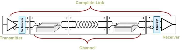
15 Source Eye Diagram Test Include Reference Cable Emulator (s4p) and Reference Cable Equalizer Tektronix Oscilloscope DPO/DSA/MSO70000 Series 16GHz Diff Clk Clk + Clk - SE Data Data + Data - SMA Pair Cable HDMI Source HDMI Plug Fixture with EDID Emulator

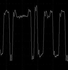
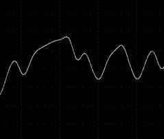
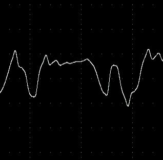
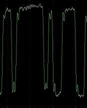
16 TP2 Source Eye for HDMI 2.0 6G Signal Single End Input eye rendered at Tek lab

17 HDMI 2.0 Tx Compliance Software

18 HDMI 2.0 Sink Testing
19 HDMI 2.0 Sink testing Equipment needs 16GHz BW scope will give 1% error and hence is recommended for HDMI 2.0 Sink testing for Jitter Verification/Calibration/Controller. P7313SMA probes Option HDM and HDM-DS HDMI 2.0 Fixture set 2# AWG7122C with Opt 01,02 or 06, 08 for HDMI 2.0 Compliance only setup. OR 2# AWG70002A with Opt 01,03 and 225 for HDMI 2.0 Compliance and Margin Test setup.(margin test feature will be available later and is part of roadmap) Note- We shall also support a 12.5GHz BW scope which would result in appx. 10% inaccuracy in RT/FT results.

20 Requirement for Signal Generation Cable Emulation and Skew by Hardware Hardware Skew and Software Cable Emulation
21 Sink Electrical tests Test ID HF2-1: Sink TMDS Electrical Mcsc Min/Max Differential Swing Tolerance Test ID HF2-2: Sink TMDS Electrical Mcsc Intra-Pair Skew Test ID HF2-3: Sink TMDS Electrical Mcsc Jitter Tolerance Test ID HF2-4: Sink TMDS Electrical Mcsc Differential Impedance (performed using sampling scope)
22 HDMI 2.0 Rx solution positioning statement Tektronix will support HDMI 2.0 Sink Electrical and protocol tests using either AWG7122C (w/ Opt 01,02/06,08) AND AWG70002A (W/ Opt 01,03,225) Solution Positioning: Compliance solution for HDMI 2.0 Rx 2# AWG7122C with opt 01, 02/06 and 08 1# AFG3102/C Customers can use common test setup for HDMI 1.4b and HDMI 2.0 giving value for their investment in Tektronix HDMI 1.4b Rx solution. Compliance and Margin solution for HDMI 2.0 Rx 2# AWG70002A with Opt 01,03 and # AFG3102/C Customers can use common test setup for HDMI 1.4b and HDMI 2.0 giving value for their investment in Tektronix HDMI 1.4b Rx solution
 Tektronix AWG70002A Tektronix Oscilloscope DPO/DSA/MSO70000 Series (Synchronize two AWGs")
23 HDMI 2.0 Sink Test Setup Tektronix AFG3000 (Synchronize two AWGs) Tektronix AWG70002A Tektronix Oscilloscope DPO/DSA/MSO70000 Series (Synchronize two AWGs and Automation Test) Include Reference Cable Emulator (s2p) 112ps Delay Line (Emulate Cable Skew) SMA Pair Cable HDMI Plug Fixture HDMI Sink
24 Sink Testing 1.4b Vs 2.0 Jitter Tolerance test needs +ve and ve lanes tested with 112ps delay line Rest of the tests is similar to HDMI 1.4b tests 1.4b CTS test is a pre-requsite for HDMI 2.0 Need AWG 70002A for HDMI 2.0 Compliance and Margin needs while AWG7122C is suitable for HDMI 2.0 Compliance testing only.. Min 8GHz scope to 16GHz scope Fixtures and Probes HDM and HDM-DS Software

25 HDMI 2.0 Rx Compliance Software
26 Tektronix HDMI 2.0 Solution Tektronix HDMI 2.0 Solution will be available aligned to the CTS announcement from the new HDMI Forum. Full Source Test Solution including probes, Fixtures. Phased Rx Electrical solution- ensuring regular engagement with customers with pattern support added to solution.( between Dec 2013 to June 2014) Release 1 HDMI 2.0 Sink Electrical tests HF2-1; HF2-2 and HF2-3 with the following VIC supported: ( Dec MOI) VIC 96,VIC97, VIC 101, VIC 102,VIC 106, VIC 107 Release 1 Sink Protocol test HF2-23 supported ( Dec MOI) Release 2 1H CY14 remaining VICs for electrical tests- Target for next MOI approval event ( Q1 CY14) Final Release - Phased Rx Protocol solution- ensuring regular engagement with customers with pattern support added to solution.( starting by Q1 CY14 and complete by end 2014) Support for HDMI 1.4b CTS is a pre-requiste for HDMI 2.0 testing. Contact local Tektronix sales team for early interaction on our HDMI 2.0 solution.
27 Introduction to USB 3.0 SuperSpeedPlus
 Shift from slower, wide, parallel buses to")


28 Increasing Serial Data Bandwidth USB 2.0, 480 Mb/s (2000) Shift from slower, wide, parallel buses to narrow, high speed serial bus 40x faster data rate, support for new connectors & charging USB 3.0, 5 Gb/s (2008) ~10x faster data rate over 3 meter cable Faster edges, closed eye architecture USB 3.0, 10 Gb/s (2013) 2x faster data rate over 1 meter cable Scaled SuperSpeed implementation
29 USB 3.0 SuperSpeedPlus Technology Timeline Test Vendor Compliance Group Participation Sept Spec Feb Spec June Spec Q Spec PIL (Peripheral Interop Lab) USB-IF Plugfests Unless noted Workshops are in Portland, OR USA Taipei Taiwan Taipei Taiwan Deployment Phase Taipei Taiwan Spec Development Spec Release Silicon Phase Integration Phase Product Development USB-IF Tool Development Tektronix Test Solution Updates Transmitter, Receiver, Channel

30 Why 10 Gb/s? Video HD video adapters with multi display outputs Dual HDMI/DVI with simultaneous 1080p displays Storage 5 Gb/s with 8b/10b -> 400 MB/s High performance SSD saturation-> ~600 MB/s Hub/Dock Multi-function, All in One docking Faster backups, multiple monitors, etc.
 at Rx Source: USB 3.")
31 5 Gb/s Key Considerations Receiver testing now required Jitter tolerance SSC, Asynchronous Ref Clocks can lead to interoperability issues Channel considerations Need to consider transmission line effects Software channel emulation for early designs New Challenges 12 Long Host Channels Closed Eye at Rx Equalization De-emphasis at Tx Continuous Time Linear Equalizer (CTLE) at Rx Source: USB 3.0 Rev 1.0 Specification
32 10 Gb/s Comparison SuperSpeed SuperSpeedPlus Data Rate 5 Gb/s 10 Gb/s Encoding 8b/10b 128b/132b Target Channel LTSSM Reference Tx EQ Reference Rx EQ JTF Bandwidth Eye Height (TP1) TJ@BER Backwards compatibility Connector 3m + Host/Device channels (-17dB, 2.5 GHz) 1m + board ref channels (-20dB, 5 GHz) LFPS, TSEQ, TS1, TS2 LFPSPlus, SCD, TSEQ, TS1, TS2, De-emphasis 3-tap (Preshoot/De-emphasis) CTLE CTLE + 1-tap DFE 4.9 MHz 7.5 MHz 100 mv 70 mv 132 ps (0.66 UI) 71 ps (0.714 UI) Y Y Std A Improved Std A with insertion detect
, need Tx optimization Repeater may be required if host/device loss > 7 db Tx/Rx compliance at TP1 (far end) 7 db 6 db 7 db Source: USB 3.")
33 Channel Budget Target 20 db (5 GHz) end-to-end loss budget Transmitter Equalization < 3.5 db (short channel), minimal loss profile 3.5 db (long channel), need Tx optimization Repeater may be required if host/device loss > 7 db Tx/Rx compliance at TP1 (far end) 7 db 6 db 7 db Source: USB 3.0 Rev 1.0 Specification
34 Reference Transmitter Equalization USB channel profiles are dynamic (consumer) Need flexible solution space for link optimization Below are recommended Tx settings for good margin with target reference channels Host/Device Loss 3.5dB 3.5dB C C Va/Vd Vb/Vd Vd/Vd
35 End-to-end PHY Validation

 Input reference")

 CP9 (TP1)")
36 Transmitter Validation Example - SDLA Capture CP9 (Scr0) and CP10 (Ah) Input reference channel models USB3 Reference Channel CP9 Scrambled Pattern (TP0) CP9 Scrambled Pattern (TP1)


37 Transmitter Validation Example - SDLA Find optimum Eye height vs. Rx EQ 40 mv - Fail 73 mv - Pass


38 Transmitter Validation Example - DPOJET Recall DPOJET SSP setups Check JTF settings (f -3db 7.5 MHz, 40dB slope)
 Postchannel")
39 Transmitter Validation Example - DPOJET Measure Eye height and jitter at TP1 Tx pins (TP0) Postchannel TP1
40 Recommended Transmitter Solution 20 GHz BW, 100 GS/sec preferred DSA72004C minimum required, DSA72504D or greater preferred >10M minimum record length allows capture of 1M UI at 100Gs/sec, no interpolation. Increase memory depth if interpolation will be enabled, or if >1MUI captures are desired. Option DJA Advanced DPOJET required, signal analysis Option SLA Advanced SDLA required, cycle through 7 CTLE/1 DFE settings Option USB3 recommended, provides USB3 TX specific measurements For instrument bandwidth, consider factors such as edge rate, reflections, SNR (de-embedding), and launch characteristics.

 Detected errors are inferred to be a result of")
41 Receiver Testing Jitter Tolerance (JTOL) with swept jitter profile, reference channel Verify CDR tracking and ISI compensation Link optimization/training critical No back channel negotiation Return echoed data to a BERT (loopback) Detected errors are inferred to be a result of bad DUT receiver decisions
42 JTOL Template Comparison (TBD) Symbol Parameter Gen 1 Gen 2 Units Notes f1 Tolerance corner MHz J Rj Random Jitter UI rms 1 J Rj_p-p Random Jitter peak- peak at UI p-p 1,4 J Pj_500kHZ Sinusoidal Jitter UI p-p 1,2,3 J Pj_1Mhz Sinusoidal Jitter UI p-p 1,2,3 J Pj_2MHz Sinusoidal Jitter UI p-p 1,2,3 J Pj_4MHz Sinusoidal Jitter N/A 0.32 UI p-p 1,2,3 J Pj_f1 Sinusoidal Jitter UI p-p 1,2,3 J Pj_50MHz Sinusoidal Jitter UI p-p 1,2,3 J Pj_100MHz Sinusoidal Jitter N/A 0.17 UI p-p 1,2,3 V_full_swing Transition bit differential voltage 0.75 TBD V p-p 1 swing V_EQ_level Non transition bit voltage -3 Pre=2.7 db 1 (equalization) Post= -3.3 Notes: 1. All parameters measured at TP1. The test point is shown in Figure Due to time limitations at compliance testing, only a subset of frequencies can be tested. However, the Rx is required to tolerate Pj at all frequencies between the compliance test points. 3. During the Rx tolerance test, SSC is generated by test equipment and present at all times. Each J Pj source is then added and tested to the specification limit one at a time. 4. Random jitter is also present during the Rx tolerance test, though it is not shown in Figure 6-1


43 BERTScope USB 3.0 RX Test Configuration USB Switch creates the low-frequency periodic signaling (LFPS) required to initiate Loopback-mode DPP125C De-emphasis Processor CR125A Clock Recovery BSA125C BERTScope

44 Summary New opportunity for growth with USB 10 Gb/s Adds additional challenges beyond legacy requirements (backwards compatibility) Higher performance, more complex design but feasible within current infrastructure Extensive PHY validation tools for early designs New USB SSP DPOJET setups for Tx validation BERTScope USB library with JTOL templates DSA8300 Sampling oscilloscope for channel characterization Test procedures documented in Methods of Implementation (MOI)


45 Debug and Validation of Flash Memory Interface Measure the Analog signal characteristics and Protocol Level Details on the flash Memory Interface


46 Memory Market Segmentation Flash 52% DRAM 48% 50

47 Flash Market Segmentation Various emmc Various emmc SATA/NVME 52
 or a two bits transfer (2x) on all the data lines. The frequency may vary between zero and the maximum clock frequency.")
48 emmc Card Concept Multimedia card transfers data via configurable data bus signals Communication Signals CLK: Each cycle of this signal directs a one bit transfer on the command and either a one bit (1x) or a two bits transfer (2x) on all the data lines. The frequency may vary between zero and the maximum clock frequency. CMD: This signal is a bidirectional command channel used for card initialization and transfer of commands. DAT0-DAT7: These are bidirectional data channels (1 bit/4 bit/8bit) Jun- 14
49 emmc Electrical measurements as emmc4.41- SDR emmc HighspeedSDR measurement for emmc4.41 Specification Parameter Min Max Unit Clock Frequency Data Transfer Node 0 52 MHz Clock frequency Indentifiction Mode KHz Clock High Time 6.5 ns Clock low Time 6.5 ns Clock rise time 3 ns Clock fall time 3 ns Inputs CMD, data (referenced to CLK) Input setup time CLK-CMD 3 ns Input hold time CLK-Data 3 ns Input set up time CLK-Data 3 ns Input hold time CLK-Data 3 ns Outputs CMD, Data (referenced to CLK) Output delay time during data transfer CLK-CMD 13.7 ns Output hold time CLK-CMD 2.5 ns Output delay time during data transfer CLK-Data 13.7 ns Output hold time CLK-Data 2.5 ns Signal Rise time 3 ns Signal fall time 3ns 55
50 emmc Electrical Measurements for Backward Compatibility emmc Highspeed SDR measurement for emmc4.41 Specification Parameter Min Max Unit Clock Frequency Data Transfer Node 0 26 MHz Clock frequency Indentifiction Mode KHz Clock High Time 10 ns Clock low Time 10 ns Clock rise time 10 ns Clock fall time 10 ns Inputs CMD, data (referenced to CLK) Input setup time CLK-CMD 3 ns Input hold time CLK-Data 3 ns Input set up time CLK-Data 3 ns Input hold time CLK-Data 3 ns Outputs CMD, Data (referenced to CLK) Output setup time CLK-CMD 11.7 ns Output hold time CLK-CMD 8.3 ns Output setuptime CLK-Data 11.7 ns Output hold time CLK-Data 8.3 ns 56
51 emmc Electrical Measurements for DDR Mode-4.41 emmc High speed DDR measurement for emmc4.41 Specification Parameter Min Max Unit Clock Duty Cycle % Inputs CMD, data (referenced to CLK) Input setuptime CLK-CMD 2.5 ns Input holdtime CLK-Data 2.5 ns Input set up time CLK-Data 2.5 ns Input hold time CLK-Data 2.5 ns Outputs CMD, Data (referenced to CLK) Output delay time during data transfer CLK-CMD ns Output delay time during data transfer CLK-Data ns Signal Rise time 2 ns Signal fall time 2 ns 57
52 Ultra High Speed cards UHS-1 provides 104 Mb/s performance with single ended performance UHS-I operation modes DS- default signaling mode supports up to 25MHz up to 3.3V HS- High speed up to 50MHz 3.3V SDR12- SDR up to 25MHz at 1.8V SDR25- SDR up to 50Mz at 1.8 SDR104- SDR upto 208MHz DDR- DDR up to 50MHz 1.8V signalling Jun- 14
53 SD Electrical Measurements SDR12 Electrical Specification of SD SDR12 Parameter Min Max Clock frequency 025Mhz Clock low time 10ns Clock high Time 10ns Clock Rise Time 10ns Clock fall time 10ns CLK-CMD Input Setup time 5ns CLk_CMD Input Hold time 5ns CLK-Data Inut Setup time 5ns CLK-CMD Input Hold time 5ns CLK-CMD Output delay ime during Data Transfer 14ns CLK-data Output Delay time during Data Transfer 14ns CLK-CMD Output delay time during Identification 50ns CLK-Data Output Delay time during Identification 50ns 61
54 SD Electrical Measurements SDR25 Electrical Specification of SD SDR25 Parameter Min Max Clock Frequency 050MHz Clock low time 7ns Clock high Time 7ns Clock Rise Time 3ns Clock fall time 3ns CLK-CMD Input Setup time 6ns CLk_CMD Input Hold time 2ns CLK-Data Inut Setup time 6ns CLK-CMD Input Hold time 2ns CLK-CMD Output delay ime during Data Transfer 14ns CLK-data Output Delay time during Data Transfer 14ns CLK-CMD output Hold Time 2.5ns CLK-DAT output delay time 2.5ns 62
55 SD Electrical measurements- SD50 Electrical Specification of SD SDR50 Parameter Min Max Clock frequency 0102MHz Clock Period 9.6ns Clock Rise Time 0.2tCLK Clock fall time 0.2tCLK Clock Duty Cycle 30% 70% CLK-CMD Input Setup time 3ns CLk_CMD Input Hold time 0.8ns CLK-Data Inut Setup time 3ns CLK-CMD Input Hold time 0.8ns CLK-CMD Output delay ime 2UI CLK-data Output Delay time 2UI CLK-CMD output vaid window 0.6UI CLK-CMD output Valid Window 0.6UI 63
56 SD Electrical Measurements SDR104 Electrical Specification of SD SDR104 Parameter Min Max Clock frequency 0208MHz Clock Period 4.8ns Clock Rise Time 0.2tCLK Clock fall time 0.2tCLK Clock Duty Cycle 30% 70% CLK-CMD Input Setup time 1.4ns CLk_CMD Input Hold time 0.8ns CLK-Data Inut Setup time 1.4ns CLK-CMD Input Hold time 0.8ns CLK-CMD Output delay ime 2UI CLK-data Output Delay time 2UI CLK-CMD output vaid window 0.6UI CLK-CMD output Valid Window 0.6UI 64
57 SD Electrical Measurements DDR50 Electrical Specification of SD DDR50 DDR50 Min Max Clock frequency 050MHz Clock Period 20ns Clock Rise Time 0.2tCLK Clock fall time 0.2tCLK Clock Duty Cycle 45% 55% CLK-CMD Input Setup time 6ns CLk_CMD Input Hold time 0.8ns CLK-Data Inut Setup time 3ns CLK-CMD Input Hold time 0.8ns CLK-CMD Output delay ime 13.7ns CLK-CMD output hold time 1.5ns CLK-data Output Delay time 7ns CLK-DAT output hold time 1.5ns 65
58 Market Needs Electrical validation of emmc as per 4.41, 4.51 and 5.0 Specification Protocol Decode of command line Protocol Analysis (tests) Protocol Timing measurements Protocol Aware Trigger Protocol Decode for long duration Protocol decode of command and Data bus 66

59 PGY-eMMC/SD Electrical Validation and Protocol Decode Software- Select User can select emmc type and data mode emmc electrical measurements as specified in emmc Standard document are listed Supports electrical measurement for emmc4.41 and 4.51 (HS200) Protocol aware measurements to support host and device measurements Flexibility to select Electrical Validation or Protocol Analysis or both or fast frame based decode and Protocol code using Digital Channel Jun- 14

60 PGY-MMC-SD Electrical Validation and Protocol Decode Software- Configure- Electrical and Protocol Analysis Select the source of the signal from oscilloscope or saved files Flexibility to select Electrical validation or Protocol Analysis or both Clock and data reference identifies signal transitions Oscilloscope setup helps is automatic oscilloscope setup or recall saved oscilloscope setup Jun- 14

61 PGY-MMC-SD Electrical Validation and Protocol Decode Software- Configure- Digital Decode Select the source of the signal from oscilloscope digital channel or saved CSV digital data file Combination of Analog and Digital Channels to reduce probe loading on CLK and CMD Select different data modes such as 1-bit SDR, 4-bit SDR, 8 bit SDR, 4 bit DDR and 8 bit DDR Set Global threshold and Digital Sampling Resolution Jun- 14

62 PGY-eMMC-SD Electrical Validation and Protocol Decode Software- Limit Setup Limits can be set to default limits as specified in standard document User has flexibility to edit the limits and apply Save and Recall the limits Jun- 14

63 PGY-MMC-SD Electrical Validation and Protocol Decode Software- Protocol Aware Trigger emmc Protocol Aware trigger capabilities Trigger on command or Response Flexibility to edit the trigger conditions Prerequisite is Serial pattern setup feature in oscilloscope Jun- 14
 List the measurements for Clock, command, response, data")
64 PGY-MMC-SD Electrical Validation and Protocol Decode Software- Analyze Displays measurement limits and annotation to indicate pass or fail Provides min, max and mean measurement values Measurements are made using the complete acquisition data, min, mean and max value for the complete acquired data (max Record length support is 125MB) List the measurements for Clock, command, response, data write and data read to cover all the electrical tests as per emmc specs Green annotation indicates test pass, orange color indicates, test may be failed for either min or max value and Red color indicates test is fail Jun- 14

65 Protocol test PGY-MMC analyses whether Protocol packets complies to specs Packet Integrity checks for number of bits per packet in command or response. Integrity between command and response checks for whether each command is receiving the expected response as per spec Reserve command presence Checks for any reserved command by host Error Flags set Response- Indicates some error flags are set in response CRC Checks in Command verifies transmitted CRC value with computed CRC by taking row packet data CRC Checks for Response- verifies transmitted CRC value with computed CRC by taking row packet data Enables Protocol checks without going through all the data Jun- 14

66 Timing View PGY-MMC-SD software checks for all timing measurements between command, Response and data Checks for number of cycles between command-response, Response-data and so forth Gives Pass/fail results Jun- 14
67 Protocol Decode using Digital Channels (MSO) Recommended use cases Case#1 Connect Digital Channel to emmc CLK, CMD and Data lines Connect CLK and CMD to Analog Channel Set emmc Protocol Trigger to trigger on read and write operation Run the application Case #2 Connect Digital Channel to emmc CLK, CMD and Data lines Set Data line falling edge as trigger condition Run the application Above cases allows you focus on decoding the datelines 81

68 Protocol Decode using Digital Channels Protocol View list decoded data Each row will have CMD, response and number data bytes Selected row details including all data bytes is displayed on right bottom Only oscilloscope based solution 82

69 PGY-MMC-SD Electrical Validation and Protocol Decode Software- Detail View Provides powerful debug environment co-relating physical layer waveform, protocol decode data and electrical measurements If any protocol packet is failed in Protocol test is highlighted in red color Selected protocol decode message waveform is plotted in selected waveform window Reference cursor will be placed in acquired waveform window to indicate the position of the waveform in Acquired data Failed Electrical measurements selected in red color Cursor measurements for manual analysis Markers to indicate reference level for measurement Take snapshot of selected waveform image from detail view for report Decode tables list the Commands and responses from card Utility features for zooming the waveform, pan, cursors, reference set markers and image capture for report Jun- 14

70 PGY-MMC-SD Electrical Validation and Protocol Decode Software- Export Export of Electrical measurements and Protocol Decode data to CSV and TXT file format Browser allows to place the data in desired location Jun- 14

71 PGY-MMC-SD Electrical Validation and Protocol Decode Software- Report Supports customizable pdf format report generation Report can include electrical measurements, protocol decode, oscilloscope images, detail view images, and reference level setup Review of saved images allows the user to add title to image, description and delete the images Jun- 14
72 Market Needs Electrical validation of emmc as per 4.41, 4.51 and 5.0 Specification (Supported; 5.0 spec by June 2014) Protocol Decode of command line (Supported) Protocol Analysis (tests) (Supported) Protocol Timing measurements (Supported) Hardware based realtime Protocol Aware Trigger (supported) Protocol Decode for long duration (Supported) Protocol decode of command and Data bus (Supported) 86
73 Competitive info Agilent Provide separate Electrical validation software for emmc and SD Tektronix & Provides single integrated emmc/sd/sdio Electrical validation and protocol Analysis Software Agilent does not provide Protocol Analysis Software LeCroy has no solution in space 87
74 Details of UPIU NOP Out NOP In Command Response Data Out Data In UPIU Data Structure Task Management Request Description The NOP Out transaction acts as a ping from an initiator to a target. It can be used to check for a connection path to a device and LUN. The NOP In transaction is a target response to an initiator when responding to a NOP In request. The Command transaction originates in the Initiator (host) and is sent to a logical unit within a Target device. A Command UPIU will contain a Command Descriptor Block as the command and the command parameters. When using the phase collapse feature the UPIU will also contain a data segment that would have been sent during the DATA OUT phase. This represents the COMMAND phase of the command. The Response transaction originates in the Target and is sent back to the Initiator (host). A Response UPIU will contain a command specific operation status and other response information. When using the phase collapse feature, the UPIU will also contain a data segment that would have been sent during the DATA IN phase. This represents the STATUS phase of the command. The Data Out transaction originates in the Initiator (host) and is used to send data from the Initiator to the Target (device). This represents the DATA OUT phase of a command. The Data In transaction originates in the Target (device) and is used to send data from the Target to the Initiator (host). This represents the DATA IN phase of a command. This transaction type carries SCSI Architecture Model (SAM) task management function requests originating at the Initiator and terminating at the Target. The standard functions are defined by the SAM 5 specification. Addition functions might be defined by UFS. This transaction type carries SCSI Architecture Model (SAM) task management function responses originating in the Target and Task Management Response terminating at the Initiator. The Target device will send a Ready To Transfer transaction when it is ready to receive the next Data Out UPIU and has sufficient buffer space to receive the data. The Target can send multiple Ready To Transfer UPIU if it has buffer space to receive multiple Data Out UPIU packets. The maximum data buffer size is negotiated between the Initiator and Target during enumeration and configuration. The Ready To Transfer UPIU contains a DMA context and can be used to setup and trigger a DMA action within a Ready To Transfer host controller Jun- 14 Query Request Query Response This transaction originates in the Initiator and is used to request descriptor data from the Target. This transaction is defined outside of the Command and Task Management functions and is defined exclusively by UFS. This transaction originates in the Target and provides requested descriptor information to the Initiator in response of the Query Request transaction. This transaction is defined outside of the Command and Task Management functions and is defined exclusively by UFS.

75 Thank You

76 99 Thank you!
Next Generation 인터페이스테크놀로지트렌드
 Next Generation 인터페이스테크놀로지트렌드 (USB3.1, HDMI2.0, MHL3.2) 텍트로닉스박영준부장 Agenda USB3.1 Compliance Test update What s different for USB3.1 Transmitter and Receiver Compliance Test HDMI2.0, MHL3.2 overview Q &
Prepare for Next Generation USB Technology Testing
 Prepare for Next Generation USB Technology Testing Disclaimer The USB 3.1 compliance test requirements are not final therefore all opinions, judgments, recommendations, etc., that are presented herein
USB 3.1 ENGINEERING CHANGE NOTICE
 Title: SSP System Jitter Budget Applied to: USB_3_1r1.0_07_31_2013 Brief description of the functional changes: Change to the 10Gbps system jitter budget. The change reduces the random jitter (RJ) budget
DisplayPort TX & RX Testing Solutions
 DisplayPort TX & RX Testing Solutions Agenda DP Technology Overview DPC TX Solution DPC RX Solution 2 DP Technology Overview 3 DisplayPort Standards Standards DP 1.2 May, 2012 DP over Type-C Spec Aug,
Receiver Testing to Third Generation Standards. Jim Dunford, October 2011
 Receiver Testing to Third Generation Standards Jim Dunford, October 2011 Agenda 1.Introduction 2. Stressed Eye 3. System Aspects 4. Beyond Compliance 5. Resources 6. Receiver Test Demonstration PCI Express
Tektronix Inc. DisplayPort Standard
 DisplayPort Standard 06-12-2008 DisplayPort Standard Tektronix MOI for Sink Tests (AWG Jitter Generation using Direct Synthesis and calibration using Real Time DPO measurements for Sink Devices) DisplayPort
Agilent E4887A HDMI TMDS Signal Generator Platform
 Agilent E4887A HDMI TMDS Signal Generator Platform Data Sheet Version 1.9 Preliminary E4887A- 007 E4887A- 037 E4887A- 003 Page Convenient Compliance Testing and Characterization of HDMI 1.3 Devices The
Logic Analysis Basics
 Logic Analysis Basics September 27, 2006 presented by: Alex Dickson Copyright 2003 Agilent Technologies, Inc. Introduction If you have ever asked yourself these questions: What is a logic analyzer? What
立肯科技 LeColn Technology
 DisplayPort PHY Validation 立肯科技 LeColn Technology 1 DisplayPort Basics Maximum bit rate DP1.2b 1.62Gb/s( RBR = reduced bit rate) 2.7Gb/s( HBR = high bit rate) 5.4Gb/s( HBR2 =high bit rate 2) DP1.3/1.4
Logic Analysis Basics
 Logic Analysis Basics September 27, 2006 presented by: Alex Dickson Copyright 2003 Agilent Technologies, Inc. Introduction If you have ever asked yourself these questions: What is a logic analyzer? What
C-PHY Essentials Transmitter Test Solution TekExpress C-PHY Essentials Tx
 C-PHY Essentials Transmitter Test Solution TekExpress C-PHY Essentials Tx Applications Camera CMOS Image sensors Display Driver ICs Application processor for Mobile devices Tektronix C-PHY TX Essentials
PAM4 signals for 400 Gbps: acquisition for measurement and signal processing
 TITLE PAM4 signals for 400 Gbps: acquisition for measurement and signal processing Image V1.00 1 Introduction, content High speed serial data links are in the process in increasing line speeds from 25
SV1C Personalized SerDes Tester. Data Sheet
 SV1C Personalized SerDes Tester Data Sheet Table of Contents 1 Table of Contents Table of Contents Table of Contents... 2 List of Figures... 3 List of Tables... 3 Introduction... 4 Overview... 4 Key Benefits...
Analyzing 8b/10b Encoded Signals with a Real-time Oscilloscope Real-time triggering up to 6.25 Gb/s on 8b/10b encoded data streams
 Presented by TestEquity - www.testequity.com Analyzing 8b/10b Encoded Signals with a Real-time Oscilloscope Real-time triggering up to 6.25 Gb/s on 8b/10b encoded data streams Application Note Application
Draft Baseline Proposal for CDAUI-8 Chipto-Module (C2M) Electrical Interface (NRZ)
 Electrical Interface (NRZ)") Draft Baseline Proposal for CDAUI-8 Chipto-Module (C2M) Electrical Interface (NRZ) Authors: Tom Palkert: MoSys Jeff Trombley, Haoli Qian: Credo Date: Dec. 4 2014 Presented: IEEE 802.3bs electrical interface
Draft Baseline Proposal for CDAUI-8 Chipto-Module (C2M) Electrical Interface (NRZ) Authors: Tom Palkert: MoSys Jeff Trombley, Haoli Qian: Credo Date: Dec. 4 2014 Presented: IEEE 802.3bs electrical interface
Agilent N6465A emmc Compliance Test Application
 Agilent N6465A emmc Compliance Test Application Methods of Implementation Agilent Technologies Notices Agilent Technologies, Inc. 2013 No part of this manual may be reproduced in any form or by any means
PCI Express. Francis Liu Project Manager Agilent Technologies. Nov 2012
 PCI Express Francis Liu Project Manager Agilent Technologies Nov 2012 PCI Express 3.0 Agilent Total Solution Physical layer interconnect design Physical layertransmitter test Physical layerreceiver test
SV1C Personalized SerDes Tester
 SV1C Personalized SerDes Tester Data Sheet SV1C Personalized SerDes Tester Data Sheet Revision: 1.0 2013-02-27 Revision Revision History Date 1.0 Document release Feb 27, 2013 The information in this
Simplifying HDMI Compliance Testing
 Simplifying HDMI Compliance Testing Tektronix Support for HDMI 1.3c and 1.4 Test Solutions 泰克中国区应用工程师 Bright Zeng Agenda HDMI Overview and Updates Compliance Test Support from Tektronix Source Tests Sink
Agilent MOI for HDMI 1.4b Cable Assembly Test Revision Jul 2012
 Revision 1.11 19-Jul 2012 Agilent Method of Implementation (MOI) for HDMI 1.4b Cable Assembly Test Using Agilent E5071C ENA Network Analyzer Option TDR 1 Table of Contents 1. Modification Record... 4 2.
Combating Closed Eyes Design & Measurement of Pre-Emphasis and Equalization for Lossy Channels
 Combating Closed Eyes Design & Measurement of Pre-Emphasis and Equalization for Lossy Channels Why Test the Receiver? Serial Data communications standards have always specified both the transmitter and
Combating Closed Eyes Design & Measurement of Pre-Emphasis and Equalization for Lossy Channels
 Combating Closed Eyes Design & Measurement of Pre-Emphasis and Equalization for Lossy Channels Why Test the Receiver? Serial Data communications standards have always specified both the transmitter and
MSO-28 Oscilloscope, Logic Analyzer, Spectrum Analyzer
 Link Instruments Innovative Test & Measurement solutions since 1986 Store Support Oscilloscopes Logic Analyzers Pattern Generators Accessories MSO-28 Oscilloscope, Logic Analyzer, Spectrum Analyzer $ The
M809256PA OIF-CEI CEI-56G Pre-Compliance Receiver Test Application
 M809256PA OIF-CEI CEI-56G Pre-Compliance Receiver Test Application Find us at www.keysight.com Page 1 Table of Contents Key Features... 3 Description... 3 Calibrations and Tests Covered by M809256PA Pre-Compliance
100G EDR and QSFP+ Cable Test Solutions
 100G EDR and QSFP+ Cable Test Solutions (IBTA, 100GbE, CEI) DesignCon 2017 James Morgante Anritsu Company Presenter Bio James Morgante Application Engineer Eastern United States james.morgante@anritsu.com
Emphasis, Equalization & Embedding
 Emphasis, Equalization & Embedding Cleaning the Rusty Channel Gustaaf Sutorius Application Engineer Agilent Technologies gustaaf_sutorius@agilent.com Dr. Thomas Kirchner Senior Application Engineer Digital
Digital Audio Design Validation and Debugging Using PGY-I2C
 Digital Audio Design Validation and Debugging Using PGY-I2C Debug the toughest I 2 S challenges, from Protocol Layer to PHY Layer to Audio Content Introduction Today s digital systems from the Digital
USB3.1 / Type-C / Power Delivery Test Challenge and Solution
 Woo Jun-Hyung / Choi Seok-Keun USB3.1 / Type-C / Power Delivery Test Challenge and Solution Page USB Type C Connector and USB3.1 Test Solution Agenda Page 3 Introduction to the USB Type C Connector USB3.1
DisplayPort 1.4 Link Layer Compliance
 DisplayPort 1.4 Link Layer Compliance Neal Kendall Product Marketing Manager Teledyne LeCroy quantumdata Product Family neal.kendall@teledyne.com April 2018 Agenda DisplayPort 1.4 Source Link Layer Compliance
DisplayPort and HDMI Protocol Analysis and Compliance Testing
 DisplayPort and HDMI Protocol Analysis and Compliance Testing Agenda DisplayPort DisplayPort Connection Sequence DisplayPort Link Layer Compliance Testing DisplayPort Main Link Protocol Analysis HDMI HDMI
SignalTap Plus System Analyzer
 SignalTap Plus System Analyzer June 2000, ver. 1 Data Sheet Features Simultaneous internal programmable logic device (PLD) and external (board-level) logic analysis 32-channel external logic analyzer 166
Next Generation Ultra-High speed standards measurements of Optical and Electrical signals
 Next Generation Ultra-High speed standards measurements of Optical and Electrical signals Apr. 2011, V 1.0, prz Agenda Speeds above 10 Gb/s: Transmitter and Receiver test setup Transmitter Test 1,2 : Interconnect,
New Serial Link Simulation Process, 6 Gbps SAS Case Study
 ew Serial Link Simulation Process, 6 Gbps SAS Case Study Donald Telian SI Consultant Session 7-TH2 Donald Telian SI Consultant About the Authors Donald Telian is an independent Signal Integrity Consultant.
Dual Link DVI Receiver Implementation
 Dual Link DVI Receiver Implementation This application note describes some features of single link receivers that must be considered when using 2 devices for a dual link application. Specific characteristics
SDLA Visualizer Serial Data Link Analysis Visualizer Software Printable Application Help
 SDLA Visualizer Serial Data Link Analysis Visualizer Software Printable Application Help *P076017306* 076-0173-06 SDLA Visualizer Serial Data Link Analysis Visualizer Software Printable Application Help
Physical Layer Compliance Testing for HDMI 1.4a Using TDSHT3 HDMI Compliance Test Software
 Physical Layer Compliance Testing for HDMI 1.4a Using TDSHT3 HDMI Compliance Test Software Application Note Introduction Termed as the catalyst for the DTV revolution, High-Definition Multimedia Interface
QPHY-USB3 USB3.0 Serial Data Operator s Manual
 QPHY-USB3 USB3.0 Serial Data Operator s Manual Revision A April, 2009 Relating to the Following Release Versions: Software Option Rev. 5.8 USB3 Script Rev. 1.0 Style Sheet Rev. 1.2 LeCroy Corporation 700
Essentials of USB-C DP Alt Mode Protocols
 Essentials of DP Alt Mode Protocols Neal Kendall Product Marketing Manager Teledyne LeCroy quantumdata Product Family neal.kendall@teledyne.com December 2018 Agenda DP Alt Mode DP Alt Mode What Is It?
980 Protocol Analyzer General Presentation. Quantum Data Inc Big Timber Road Elgin, IL USA Phone: (847)
") 980 Protocol Analyzer General Presentation 980 Protocol Analyzer For HDMI 1.4a & MHL Sources Key Features and Benefits Two 980 products offered: Gen 2 provides full visibility into HDMI protocol, timing,
980 Protocol Analyzer General Presentation 980 Protocol Analyzer For HDMI 1.4a & MHL Sources Key Features and Benefits Two 980 products offered: Gen 2 provides full visibility into HDMI protocol, timing,
quantumdata 980 Series Test Systems Overview of UHD and HDR Support
 quantumdata 980 Series Test Systems Overview of UHD and HDR Support quantumdata 980 Test Platforms 980B Front View 980R Front View 980B Advanced Test Platform Features / Modules 980B Test Platform Standard
Eye Doctor II Advanced Signal Integrity Tools
 Eye Doctor II Advanced Signal Integrity Tools EYE DOCTOR II ADVANCED SIGNAL INTEGRITY TOOLS Key Features Eye Doctor II provides the channel emulation and de-embedding tools Adds precision to signal integrity
Quick Reference Manual
 Quick Reference Manual V1.0 1 Contents 1.0 PRODUCT INTRODUCTION...3 2.0 SYSTEM REQUIREMENTS...5 3.0 INSTALLING PDF-D FLEXRAY PROTOCOL ANALYSIS SOFTWARE...5 4.0 CONNECTING TO AN OSCILLOSCOPE...6 5.0 CONFIGURE
Keysight E4887A HDMI TMDS Signal Generator Platform. Data Sheet Version 2.1
 Keysight E4887A HDMI TMDS Signal Generator Platform Data Sheet Version 2.1 02 Keysight E4887A HDMI TMDS Signal Generator Platform - Data Sheet Convenient Compliance Testing and Characterization of HDMI
CAN, LIN and FlexRay Protocol Triggering and Decode for Infiniium 9000A and 9000 H-Series Oscilloscopes
 CAN, LIN and FlexRay Protocol Triggering and Decode for Infiniium 9000A and 9000 H-Series Oscilloscopes Data sheet This application is available in the following license variations. Order N8803B for a
Keysight Method of Implementation (MOI) for VESA DisplayPort (DP) Standard Version 1.3 Cable-Connector Compliance Tests Using E5071C ENA Option TDR
 for VESA DisplayPort (DP) Standard Version 1.3 Cable-Connector Compliance Tests Using E5071C ENA Option TDR") Revision 1.00 February 27, 2015 Keysight Method of Implementation (MOI) for VESA DisplayPort (DP) Standard Version 1.3 Cable-Connector Compliance Tests Using E5071C ENA Option TDR 1 Table of Contents 1.
Revision 1.00 February 27, 2015 Keysight Method of Implementation (MOI) for VESA DisplayPort (DP) Standard Version 1.3 Cable-Connector Compliance Tests Using E5071C ENA Option TDR 1 Table of Contents 1.
Keysight Technologies M8048A ISI Channels
 Keysight Technologies M8048A ISI Channels Master Your Next Designs Data Sheet Key features Emulate a wide range of channel loss with cascadable ISI traces with fine resolution 4 short (7.7 to 12.8 ) and
Datasheet SHF A
 SHF Communication Technologies AG Wilhelm-von-Siemens-Str. 23D 12277 Berlin Germany Phone +49 30 772051-0 Fax ++49 30 7531078 E-Mail: sales@shf.de Web: http://www.shf.de Datasheet SHF 19120 A 2.85 GSa/s
Practical De-embedding for Gigabit fixture. Ben Chia Senior Signal Integrity Consultant 5/17/2011
 Practical De-embedding for Gigabit fixture Ben Chia Senior Signal Integrity Consultant 5/17/2011 Topics Why De-Embedding/Embedding? De-embedding in Time Domain De-embedding in Frequency Domain De-embedding
The Challenges of Measuring PAM4 Signals
 TITLE The Challenges of Measuring PAM4 Signals Panelists: Doug Burns, SiSoft Stephen Mueller, Teledyne LeCroy Luis Boluña, Keysight Technologies Mark Guenther, Tektronix Image Jose Moreira, Advantest Martin
DATA SHEET. Two (2) fibers Detachable HDMI 2.0 Extender,
 fibers Detachable HDMI 2.0 Extender,") DATA SHEET Two (2) fibers Detachable HDMI 2.0 Extender, HDFX-300-TR Contents Description Features Applications Technical Specifications Operating Conditions Drawing of Module Drawing of Cable Connection
DATA SHEET Two (2) fibers Detachable HDMI 2.0 Extender, HDFX-300-TR Contents Description Features Applications Technical Specifications Operating Conditions Drawing of Module Drawing of Cable Connection
TekExpress Ethernet Tx Compliance Solution Printable Application Help
 TekExpress Ethernet Tx Compliance Solution Printable Application Help *P077125300* 077-1253-00 TekExpress Ethernet Tx Compliance Solution Printable Application Help www.tek.com 077-1253-00 Copyright Tektronix.
Meeting Embedded Design Challenges with Mixed Signal Oscilloscopes
 Meeting Embedded Design Challenges with Mixed Signal Oscilloscopes Introduction Embedded design and especially design work utilizing low speed serial signaling is one of the fastest growing areas of digital
PCIe: EYE DIAGRAM ANALYSIS IN HYPERLYNX
 PCIe: EYE DIAGRAM ANALYSIS IN HYPERLYNX w w w. m e n t o r. c o m PCIe: Eye Diagram Analysis in HyperLynx PCI Express Tutorial This PCI Express tutorial will walk you through time-domain eye diagram analysis
ASNT_PRBS20B_1 18Gbps PRBS7/15 Generator Featuring Jitter Insertion, Selectable Sync, and Output Amplitude Control
 ASNT_PRBS20B_1 18Gbps PRBS7/15 Generator Featuring Jitter Insertion, Selectable Sync, and Output Amplitude Control Broadband frequency range from 20Mbps 18.0Gbps Minimal insertion jitter Fast rise and
Identifying Setup and Hold Violations with a Mixed Signal Oscilloscope APPLICATION NOTE
 Identifying Setup and Hold Violations with a Mixed Signal Oscilloscope Introduction Timing relationships between signals are critical to reliable operation of digital designs. With synchronous designs,
Keysight Technologies CAN/LIN Measurements (Option AMS) for InfiniiVision Series Oscilloscopes
 for InfiniiVision Series Oscilloscopes") Ihr Spezialist für Mess- und Prüfgeräte Keysight Technologies CAN/LIN Measurements (Option AMS) for InfiniiVision Series Oscilloscopes Data Sheet Introduction Debug the signal integrity of your CAN and
Ihr Spezialist für Mess- und Prüfgeräte Keysight Technologies CAN/LIN Measurements (Option AMS) for InfiniiVision Series Oscilloscopes Data Sheet Introduction Debug the signal integrity of your CAN and
QPHY-HDMI2 Operator s Manual
 QPHY-HDMI2 Operator s Manual Revision B November, 2017 Relating to: XStreamDSO Version 8.5.x.x QualiPHY Version 8.5.x.x 700 Chestnut Ridge Road Chestnut Ridge, NY, 10977-6499 Tel: (845) 425-2000, Fax:
Jitter and Eye Fundamental & Application. Jacky Huang AE, Tektronix Taiwan
 Jitter and Eye Fundamental & Application Jacky Huang AE, Tektronix Taiwan Agenda Background Information Jitter Basics What is Jitter? TIE vs. Period Jitter vs. Cycle-to-Cycle Clock Recovery Jitter Visualization
Electrical Sampling Modules Datasheet 80E11 80E11X1 80E10B 80E09B 80E08B 80E07B 80E04 80E03 80E03-NV
 Electrical Sampling Modules Datasheet 80E11 80E11X1 80E10B 80E09B 80E08B 80E07B 80E04 80E03 80E03-NV The DSA8300 Series Sampling Oscilloscope, when configured with one or more electrical sampling modules,
10GBASE-LRM Interoperability & Technical Feasibility Report
 10GBASE-LRM Interoperability & Technical Feasibility Report Dan Rausch, Mario Puleo, Hui Xu Agilent Sudeep Bhoja, John Jaeger, Jonathan King, Jeff Rahn Big Bear Networks Lew Aronson, Jim McVey, Jim Prettyleaf
32 G/64 Gbaud Multi Channel PAM4 BERT
 Product Introduction 32 G/64 Gbaud Multi Channel PAM4 BERT PAM4 PPG MU196020A PAM4 ED MU196040A Signal Quality Analyzer-R MP1900A Series Outline of MP1900A series PAM4 BERT Supports bit error rate measurements
LMH0340/LMH0341 SerDes EVK User Guide
 LMH0340/LMH0341 SerDes EVK User Guide July 1, 2008 Version 1.05 1 1... Overview 3 2... Evaluation Kit (SD3GXLEVK) Contents 3 3... Hardware Setup 4 3.1 ALP100 BOARD (MAIN BOARD) DESCRIPTION 5 3.2 SD340EVK
Boosting Performance Oscilloscope Versatility, Scalability
 Boosting Performance Oscilloscope Versatility, Scalability Rising data communication rates are driving the need for very high-bandwidth real-time oscilloscopes in the range of 60-70 GHz. These instruments
40G SWDM4 MSA Technical Specifications Optical Specifications
 40G SWDM4 MSA Technical Specifications Specifications Participants Editor David Lewis, LUMENTUM The following companies were members of the SWDM MSA at the release of this specification: Company Commscope
quantumdata 980 Series Test Systems Overview of Applications
 quantumdata 980 Series Test Systems Overview of Applications quantumdata 980 Series Platforms and Modules quantumdata 980 Test Platforms 980B Front View 980R Front View 980B Advanced Test Platform Features
Synthesized Clock Generator
 Synthesized Clock Generator CG635 DC to 2.05 GHz low-jitter clock generator Clocks from DC to 2.05 GHz Random jitter
BRR Tektronix BroadR-Reach Compliance Solution for Automotive Ethernet. Anshuman Bhat Product Manager
 BRR Tektronix BroadR-Reach Compliance Solution for Automotive Ethernet Anshuman Bhat Product Manager anshuman.bhat@tektronix.com Agenda BroadR-Reach Automotive Market Technology Overview Open Alliance
Comparison of NRZ, PR-2, and PR-4 signaling. Qasim Chaudry Adam Healey Greg Sheets
 Comparison of NRZ, PR-2, and PR-4 signaling Presented by: Rob Brink Contributors: Pervez Aziz Qasim Chaudry Adam Healey Greg Sheets Scope and Purpose Operation over electrical backplanes at 10.3125Gb/s
Serial Data Link Analysis Visualizer (SDLA Visualizer) Option SDLA64, DPOFL-SDLA64
 Option SDLA64, DPOFL-SDLA64") Serial Data Link Analysis Visualizer (SDLA Visualizer) Option SDLA64, DPOFL-SDLA64 SDLA Visualizer and DPOJET with simultaneous views of a PCI Express 3.0 acquired signal, signal after compliance channel
Serial Data Link Analysis Visualizer (SDLA Visualizer) Option SDLA64, DPOFL-SDLA64 SDLA Visualizer and DPOJET with simultaneous views of a PCI Express 3.0 acquired signal, signal after compliance channel
GT Dual-Row Nano Vertical SMT High Speed Characterization Report For Differential Data Applications
 GT-16-95 Dual-Row Nano Vertical SMT For Differential Data Applications 891-011-15S Vertical SMT PCB 891-001-15P Cable Mount Revision History Rev Date Approved Description A 6/3/2016 R. Ghiselli/D. Armani
Solutions to Embedded System Design Challenges Part II
 Solutions to Embedded System Design Challenges Part II Time-Saving Tips to Improve Productivity In Embedded System Design, Validation and Debug Hi, my name is Mike Juliana. Welcome to today s elearning.
InfiniBand Trade Association
 InfiniBand Trade Association Revision 1.04 2/27/2014 IBTA Receiver MOI for FDR Devices For Tektronix BERTScope Bit Error Rate Tester and Agilent 86100D with module 86108B and FlexDCA S/W for stressed signal
SMPTE STANDARD Gb/s Signal/Data Serial Interface. Proposed SMPTE Standard for Television SMPTE 424M Date: < > TP Rev 0
 Proposed SMPTE Standard for Television Date: TP Rev 0 SMPTE 424M-2005 SMPTE Technology Committee N 26 on File Management and Networking Technology SMPTE STANDARD- --- 3 Gb/s Signal/Data Serial
Switching Solutions for Multi-Channel High Speed Serial Port Testing
 Switching Solutions for Multi-Channel High Speed Serial Port Testing Application Note by Robert Waldeck VP Business Development, ASCOR Switching The instruments used in High Speed Serial Port testing are
40 Gb/s PatternPro Programmable Pattern Generator PPG4001 Datasheet
 40 Gb/s PatternPro Programmable Pattern Generator PPG4001 Datasheet The Tektronix PPG4001 PatternPro programmable pattern generator provides stressed pattern generation for high-speed Datacom testing.
Agilent Technologies Pulse Pattern and Data Generators Digital Stimulus Solutions
 Agilent Technologies Pattern and Data Generators Digital Stimulus Solutions Leading pulse, pattern, data and clock generation for all test needs in digital design and manufacturing Pattern Generators Agilent
DisplayPort Standard. Agilent, Inc. Draft2 January 14, 2013
 Agilent, Inc. DisplayPort Standard Draft2 January 14, 2013 Agilent MOI for DisplayPort PHY CTS 1.2b Source Testing Using DSA90000A/90000X/90000Q Series Oscilloscopes with U7232B DisplayPort Compliance
Reference. TDS7000 Series Digital Phosphor Oscilloscopes
 Reference TDS7000 Series Digital Phosphor Oscilloscopes 07-070-00 0707000 To Use the Front Panel You can use the dedicated, front-panel knobs and buttons to do the most common operations. Turn INTENSITY
12G-SDI Physical Layer Analysis using the Ultra 4K Tool Box
 12G-SDI Physical Layer Analysis using the Ultra 4K Tool Box Authors: Alan Wheable FISTC, MITOL Senior Technical Author, Alex Huntley MEng Senior Consultant and Andy McMinn BEng Senior Consultant at Omnitek
Essentials of HDMI 2.1 Protocols
 Essentials of HDMI 2.1 Protocols for 48Gbps Transmission Neal Kendall Product Marketing Manager Teledyne LeCroy quantumdata Product Family neal.kendall@teledyne.com December 19, 2017 Agenda Brief review
ELECTRICAL PERFORMANCE REPORT
 CIRCUITS & DESIGN ELECTRICAL PERFORMANCE REPORT DENSIPAC 4 ROW Date: 06-12-2006 Circuits & Design EMEA Circuits & Design 1/21 06/12/2006 1 INTRODUCTION... 3 2 CONNECTORS, TEST BOARDS AND TEST EQUIPMENT...
2016 PDV Conference. Time Alignment of Multiple Real-Time High Bandwidth Scope. Channels
 Time Alignment of Multiple Real-Time High Bandwidth Scope Channels 1 Time Synchronization Between Scope Channels for Data Acquisition Large Acquisition Systems Often Require Synchronization of Multiple
Agilent Test Solutions for HDMI Thorough characterization and validation of HDMI-based designs
 Agilent Test Solutions for HDMI Thorough characterization and validation of HDMI-based designs New Challenges The High-Defi nition Multimedia Interface (HDMI) is being implemented broadly in devices from
Manual Supplement. This supplement contains information necessary to ensure the accuracy of the above manual.
 Manual Title: 9500B Users Supplement Issue: 2 Part Number: 1625019 Issue Date: 9/06 Print Date: October 2005 Page Count: 6 Version 11 This supplement contains information necessary to ensure the accuracy
Oscilloscope Measurement Tools to Help Debug Automotive Serial Buses Faster
 Oscilloscope Measurement Tools to Help Debug Automotive Serial Buses Faster Application Note Introduction The primary reason engineers use oscilloscopes to debug and characterize automotive serial buses,
GT Dual-Row Nano Vertical Thru-Hole High Speed Characterization Report For Differential Data Applications
 GT-16-97 Dual-Row Nano Vertical Thru-Hole For Differential Data Applications 891-007-15S Vertical Thru-Hole PCB 891-001-15P Cable Mount Revision History Rev Date Approved Description A 8/31/2016 R. Ghiselli/G.
Agilent N4965A Multi-Channel BERT 12.5 Gb/s Data Sheet
 Agilent Multi-Channel BERT 2.5 Gb/s Data Sheet Highly cost effective solution for characterizing crosstalk susceptibility, backplanes and multi-lane serial data systems Product highlights Modular architecture
Debugging Memory Interfaces using Visual Trigger on Tektronix Oscilloscopes
 Debugging Memory Interfaces using Visual Trigger on Tektronix Oscilloscopes Application Note What you will learn: This document focuses on how Visual Triggering, Pinpoint Triggering, and Advanced Search
Features. For price, delivery, and to place orders, please contact Hittite Microwave Corporation:
 HMC-C1 Typical Applications The HMC-C1 is ideal for: OC-78 and SDH STM-25 Equipment Serial Data Transmission up to 5 Gbps Short, intermediate, and long haul fiber optic applications Broadband Test and
F M1SDI 1 Ch Tx & Rx. HD SDI Fiber Optic Link with RS 485. User Manual
 User Manual F M1SDI 1 Ch Tx & Rx HD SDI Fiber Optic Link with RS 485 User Manual 1Introduction 1.1Overview 1.2Features 1.3Application 2 Panel 2.1 Front Panel 2.2 Rear Panel 3Technical Specification Contents
Keysight N4965A Multi-Channel BERT 12.5 Gb/s. Data Sheet
 Keysight Multi-Channel BERT 2.5 Gb/s Data Sheet 02 Keysight Multi-Channel BERT 2.5 Gb/s - Data Sheet Highly cost effective solution for characterizing crosstalk susceptibility, backplanes and multi-lane
CAN/LIN Measurements (Option AMS) for Agilent s InfiniiVision Series Oscilloscopes
 for Agilent s InfiniiVision Series Oscilloscopes") CAN/LIN Measurements (Option AMS) for Agilent s InfiniiVision Series Oscilloscopes Data Sheet Debug the signal integrity of your CAN and LIN designs faster Introduction The Agilent Technologies InfiniiVision
CAN/LIN Measurements (Option AMS) for Agilent s InfiniiVision Series Oscilloscopes Data Sheet Debug the signal integrity of your CAN and LIN designs faster Introduction The Agilent Technologies InfiniiVision
Technical Article MS-2714
 . MS-2714 Understanding s in the JESD204B Specification A High Speed ADC Perspective by Jonathan Harris, applications engineer, Analog Devices, Inc. INTRODUCTION As high speed ADCs move into the GSPS range,
Measurements and Simulation Results in Support of IEEE 802.3bj Objective
 Measurements and Simulation Results in Support of IEEE 802.3bj Objective Jitendra Mohan, National Semiconductor Corporation Pravin Patel, IBM Zhiping Yang, Cisco Peerouz Amleshi, Mark Bugg, Molex Sep 2011,
De-embedding Gigaprobes Using Time Domain Gating with the LeCroy SPARQ
 De-embedding Gigaprobes Using Time Domain Gating with the LeCroy SPARQ Dr. Alan Blankman, Product Manager Summary Differential S-parameters can be measured using the Gigaprobe DVT30-1mm differential TDR
40 Gb/s PatternPro Programmable Pattern Generator PPG4001 Datasheet
 40 Gb/s PatternPro Programmable Pattern Generator PPG4001 Datasheet Applications Semiconductor device testing Optical component testing Transceiver module testing The Tektronix PPG4001 PatternPro programmable
The Measurement Tools and What They Do
 2 The Measurement Tools The Measurement Tools and What They Do JITTERWIZARD The JitterWizard is a unique capability of the JitterPro package that performs the requisite scope setup chores while simplifying
Memory Interface Electrical Verification and Debug
 Memory Interface Electrical Verification and Debug DDRA Datasheet Address/Command Bus Capture: The MSO5000 or MSO70000 Series Mixed Signal Oscilloscope can be used precisely qualify timing of ADD/DMD bus
o-microgigacn Data Sheet Revision Channel Optical Transceiver Module Part Number: Module: FPD-010R008-0E Patch Cord: FOC-CC****
 o-microgigacn 4-Channel Optical Transceiver Module Part Number: Module: FPD-010R008-0E Patch Cord: FOC-CC**** Description Newly developed optical transceiver module, FUJITSU s o-microgigacn series supports
Dual Link DVI Receiver Implementation
 Dual Link DVI Receiver Implementation This application note describes some features of single link receivers that must be considered when using 2 devices for a dual link application. Specific characteristics