Emphasis, Equalization & Embedding
|
|
|
- Linette Young
- 5 years ago
- Views:
Transcription


1 Emphasis, Equalization & Embedding Cleaning the Rusty Channel Gustaaf Sutorius Application Engineer Agilent Technologies Dr. Thomas Kirchner Senior Application Engineer Digital Debug Tools Page 1 Cleaning The Rusty Channel Emphasis, Equalization & Embedding
2 Agenda 1. Introduction 2. Emphasis 3. Equalization 4. Virtual probing by De-Embedding 5. PrecisionProbe Concept 6. Summary Page 2 Cleaning The Rusty Channel Emphasis, Equalization & Embedding


3 3 E s: Signal Conditioning & Measuring TX Channel RX Emphasis: Pre-emphasis De-emphasis Embedding: De-embed path Emulate path Equalization: Passive (Linear Feedforward Eq.) Active (Decision Feedback Eq.)


4 Key measure is eye quality Unequalized 1Gb/s Unequalized 3Gb/s Unequalized 5Gb/s Unequalized 8Gb/s Page 4 Cleaning The Rusty Channel Emphasis, Equalization & Embedding


5 How to clean the rusty channel De-emphasis Equalisation Page 5 Cleaning The Rusty Channel Emphasis, Equalization & Embedding
6 Agenda 1. Introduction 2. Emphasis 3. Equalization 4. Virtual probing by De-Embedding 5. PrecisionProbeConcept 6. Summary Page 6 Cleaning The Rusty Channel Emphasis, Equalization & Embedding


7 Transmitter De-emphasis We can account for loss through the channel at the transmitter with transmitter de-emphasis. De-emphasis is also called preemphasis. The amount of de-emphasis may be programmable. De-emphasis off, measured at receiver De-emphasis on, measured at transmitter De-emphasis on, measured at receiver Page 7 Cleaning The Rusty Channel Emphasis, Equalization & Embedding


8 ExampleDe-Emphasis Channel Input signal Channel Output signal Source: appnote on emphasis Page 8 Cleaning The Rusty Channel Emphasis, Equalization & Embedding


9 De-EmphasiswithN4916A (De-Emphasis Signal Converter) Positive de-emphasis programming start of pulse Negative de-emphasis programming end of pulse Note: de-emphasis is sometimes called also pre-emphasis. Used in standards: PCI Express 1 and 2, SATA 3G b/s, fully buffered DIMM, Hypertransport, CEI 6/11G, 10 GbEthernet. Page 9 Cleaning The Rusty Channel Emphasis, Equalization & Embedding

10 5 Gb/s in out no deemphasis optimized deemphasis With N4916A Page 10 Cleaning The Rusty Channel Emphasis, Equalization & Embedding
11 Agenda 1. Introduction 2. Emphasis 3. Equalization 4. Virtual probing by De-Embedding 5. PrecisionProbe Concept 6. Summary Page 11 Cleaning The Rusty Channel Emphasis, Equalization & Embedding


12 Equalization: Serial Data Equalization N5461A The Serial Data Equalization software is innovative software for the Series that allows for real time equalization of partially or completely closed eyes. Serial Data Equalization provides the following: Modeling of both DFE and FFE Automated tap value creation Basic de-embedding capability Full integration with the Series software Real time updating Equalization wizard Full cursor control to measure eye height The idea behind equalization is to use the voltage levels of the other bits to correct the voltage level of the current bit. Page 12 Cleaning The Rusty Channel Emphasis, Equalization & Embedding
 = 16k 0 + 202k 1 + 182k 2 + 160k 3 + 81k 4 105k 5 37k")

13 FFE Concept an Example Tap the pre-cursors to equalize the bit Bit number: mv 81 mv 182 mv 202 mv -37 mv 160 mv -16 mv -105 mv Equalized signal, e(0) = 16k k k k k 4 105k 5 37k k 7 k i are correction constants called Taps The bits before the bit of interest are called pre-cursors The bits after the bit of interest are called post-cursors Cleaning The Rusty Channel Emphasis, Equalization & Embedding
14 Basic Theory Why Equalization Works The Impulse Response h(t) has all the information contained in a circuit element. Transmission path δ (t) h(t) To get the best taps, we need to invert the process h(t) Equalizer Delay Delay... x x x x e(t) +

 2.")


15 N5461A Serial Data Equalization Provides a Complete Equalization Wizard and Automated Tap Values 1. Wizard allows for seven real time eye options (including DFE and FFE on a closed eye) 2. Wizard provides full step by step process for clock recovery 3. Wizard provides tap value automation via the FFE and DFE setup menus 4. Wizard makes setting up equalization fast and easy Page 15 Cleaning The Rusty Channel Emphasis, Equalization & Embedding


16 N5461A Equalization Wizard options FFE is applied, but the real time eye is not displayed. You will see only the waveform. 2. No equalization applied. This is to compare an equalized signal versus a nonequalized signal. 3. FFE is applied only to recover the clock, but the referenced eye is unequalized. This is useful forfindingthe recovered clock from a closed eye. 4. Standard FFE equalization. 5. Standard DFE equalization for a non closed eye. 6. Standard DFE equalization for a closed eye. Note the FFE is used to recover the clock, but is notdisplayedin the real time eye. 7. FFE is applied and then DFE is applied to the real time eye. Both are displayed in the resulting realtime eye. Page 16 Cleaning The Rusty Channel Emphasis, Equalization & Embedding


17 N5461A Equalization Wizard options Page 17 Cleaning The Rusty Channel Emphasis, Equalization & Embedding
18 Equalizer demonstration 81134A as ideal source Bad cable or JIM as medium scope as receiver with N5461A equalizer Page 18 Cleaning The Rusty Channel Emphasis, Equalization & Embedding


19 FFE Results taken from the Serial Data Equalization SW Page 19 Cleaning The Rusty Channel Emphasis, Equalization & Embedding
20 Agenda 1. Introduction 2. Emphasis 3. Equalization 4. Virtual probing by De-Embedding 5. PrecisionProbeConcept 6. Summary 7. Addendum: Practical examples Page 20 Cleaning The Rusty Channel Emphasis, Equalization & Embedding
21 De-embedding Fixtures or PCB Traces TP0 TP1 TP2 TP3 TP4 + Tx - EQ Txp Txn Connector Channel Connector Rxp Rxn EQ + Rx - Signal generated here Exits IC here Exits board here Combine measurements and transmission line models to view simulated scope measurements at any location in your design Intuitive GUI speeds setup 21
22 Virtual Probing = Measurement Plane Relocation M What you Have Measurement Plane Connector Fixture Cable Waveform Analyzer Digital Source 50Ω Realtime Oscilloscope= Waveform Analyzer What you Want Digital Source Connector Fixture Cable S Simulated Measurement Plane 50Ω Instrument Termination Page 22 Cleaning The Rusty Channel Emphasis, Equalization & Embedding
23 Removing a Channel Element De-Embedding Compensate for Probing and Fixture Loss Add Margin to Transmitter Characterization TP2 TP1 PCI Express 2, SATA, and Custom Compliance Requirement for Gen 2 Tx Connector Channel Connector Rx PHY PHY TP1 TP2 Page 23 Cleaning The Rusty Channel Emphasis, Equalization & Embedding


24 Agilent De-Embedding Representation: InfiniiSim Example Remove Insertion Loss of 1 Channel Element Page 24 Cleaning The Rusty Channel Emphasis, Equalization & Embedding


25 InfiniiSim: Go as Detailed as you need From 1 block To 9 blocks T= Tx, R = Rx, M = scope, S= Virtual probing point Page 25 Cleaning The Rusty Channel Emphasis, Equalization & Embedding


26 InfiniiSimExample: De-embedding of cable effect Generate 3Gb/s PRBS7 signal Go through 6 meters of cable TX Removal TX Page 26 Cleaning The Rusty Channel Emphasis, Equalization & Embedding


")

27 InfiniiSim Example: De-Embedding of 6 meter Cable We are going to perform a Transformation of a Waveform ACQUISITION of signal through 6 meters of cable Simulated Result of removing the cable Transfer Function R(t) H(t) = S(t) Page 27 Cleaning The Rusty Channel Emphasis, Equalization & Embedding

28 InfiniiSim Example: De-Embedding DDR2 BGA Probe TRANSIENT S-PARAMETERS Tran Tran1 StopTime=3.0 nsec MaxTimeStep=1.0 nsec SPOutput spoutput1 FileName= FileType=touchstone Format=MA S_Param SP1 Start=50 Mhz Stop=20 GHz Step=0.01 GHz R Term9 R=50 Ohm Vic2_Probe System Aggr_Top Vic2_Bot t VtStep SRC1 Vlow=0 V Vhigh=2 V Delay=.1 nsec Rise=1 psec Term Term1 Num=1 Z=75 Ohm Term Term2 Num=2 Z=75 Ohm Term Term3 Num=3 Z=75 Ohm S2P_Eqn S2P1 S[1,1]=0 S[1,2]=0.01 S[2,1]=sqrt(29050/75) S[2,2]=0 Z[1]=29050 Z[2]=75 DRAM Probe_out Aggr_Bot Aggr_Probe Vic1_Top Vic1_Bot Vic2_Top Vic1_Probe R Term4 R=75 Ohm R Term6 R=75 Ohm W2635_36_RevA1_Model_NoProbe_SUBCKT X1 R Term7 R=75 Ohm R Term8 R=75 Ohm C C1 C=.24 pf R Term5 R=75 Ohm 28 May 28th, 2009


29 Probe at VIA De-embed Probe Probe at BGA InfiniiSim Example: De-Embedding DDR2 BGA Probe RT BGA = 390 ps RT VIA = 183 ps RT De-embed = 175 ps 29 May 28th, 2009
30 Full De-Embedding versus Insertion Loss Removal V Meas (t) TX Channel Element A Channel Element B Channel Element C F u l l D e - E m b e d d i n g VS. TX Channel Element B I n s e r t i o n L o s s R e m o v a l

31 System Model TX A B C S 21Tx S 21A S 21B S S 21C 21Rx S 22Tx = 0 S 11A S 22A S 11B S 22B S 11Rx = 0 S 11C S 22C C o r r e c t A n s w e r S 12A S 12B S 12C TF ABC = S 21A *S 21B *S 21C 1 (S 22A *S 11B + S 22B *S 11C + S 21B *S 11C *S 12B *S 22A )
32 Comparing the two: Insertion Loss Removal I n s e r t i o n L o s s R e m o v a l U s e s e a s y s c o p e m a t h : S 21B -1 TX A B C S 21Tx S 22Tx = 0 S 21A S 21B S 21C S 11A S 22A S 11B S 22B S 11C S 22C S 21B -1 G i v e n A n s w e r TF ABC = S 12A S 12B S 21A *S 21B *S 21C S 21B -1 S 12C Easy Scope Math 1 (S 22A *S 11B + S 22B *S 11C + S 21B *S 11C *S 12B *S 22A ) I n t e r a c t i o n A r t i f a c t s A r e S t i l l T h e r e!!!
33 Comparing the two: true removal of block B F u l l D e - E m b e d B TX A C S 21Tx S 21A S 21C S 21Rx S 21C S S 11A S 22A S 11C S 22C 22Tx = 0 S 11Rx = 0 S 12A S 12C C o r r e c t A n s w e r TF AC = S 21A *S 21C 1 (S22A*S11C)
34 Comparing the two: Full De-embed F u l l D e - E m b e d u s e s c o m p l e x s c o p e m a t h t h a t r e m o v e s a l s o i n t e r a c t i o n a r t i f a c t s ( i n t h i s c a s e b e t w e e n A - B a n d B - C a n d A - B - C ) : F u l l D e - E m b e d As measured TX S 21Tx S 22Tx = 0 A B C S 21A S 21B S 21C S 11A S 22A S 11B S 22B S 11C S 22C Complex Function Scope Math S 12A S 12B S 12C TF AC = S 21A *S 21B *S 21C [1 (S 22A *S 11B + S 22B *S 11C + S 21B *S 11C *S 12B *S 22A )] S 21B -1 [1 (S 22A *S 11B + S 22B *S 11C + S 21B *S 11C *S 12B *S 22A )] [1 (S 22A *S 11C )] I n t e r a c t i o n A r t i f a c t s A r e R e m o v e d!!!
35 DEMO InfiniiSim Virtual Probing Test Fixture to De-Embed Page 35


36 DEMO JIM & INFINIISIM 81134A/ Setup at Amstelveen Office Infiniisim OFF Infiniisim ON Page 36
37 Agenda 1. Introduction 2. Emphasis 3. Equalization 4. Virtual probing by De-Embedding 5. PrecisionProbe Concept 6. Summary 7. Addendum: Practical examples Page 37
 Characterize")

38 Changing scopes into VNA s using PrecisionProbe (N2809A) Characterize and correct any input path to your oscilloscope input using only your oscilloscope
39 The problem: a real life example Customers challenge: To characterize and correctly identify every path in this switch system. Then to remove any insertion loss from the path to maximize margins Fix #1: Use a VNA/TDR to characterize all paths, correctly identify each, and use InfiniiSim to remove the loss Fix #2: PrecisionProbe! Customer currently uses PrecisionProbe to characterize and compensate for all 112 input paths resulting time savings and margin gains with every measurement Recently a customer gained 15% in their margins by using PrecisionProbe, they now pass their PCIE gen3 testing
 magnitude and phase of any probe and probe")

40 The Solution: PrecisionProbe PrecisionProbe Quickly and Easily: - Characterizes and corrects the frequency response (VOut/VIn) magnitude and phase of any probe and probe head combination - Characterizes and corrects for insertion loss caused by cables and fixtures - Characterizes and corrects for insertion loss caused by switches for probes and cables.
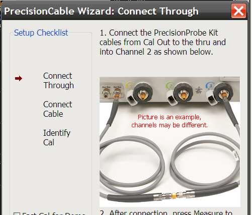
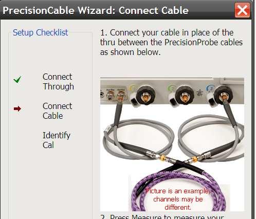
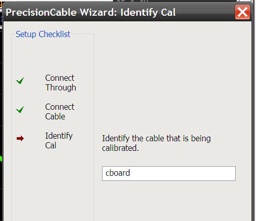
41 PrecisionCable characterizes and corrects in three easy steps 1. Measure baseline 2. Measure loss due to cable 3. Save File Page 41


42 How it works Agilent s X- Series uses its world class 200 GHz Indium Phosphide technology to provide a <15ps edge to the oscilloscope Comparing the baseline measurement with the cables influence, proper characterization is done and corrections can be made Infiniium s custom InP calibration edge Fast edge or Baseline Calibration edge is then measured by the X-Series Edge with lossy cable Lossy cable is then measured agai inst the fast edge e


43 Cable characterized with PrecisionProbe Applied corrected filter Response of cable with no correction Corrected cable response


44 Cable correction results Before PrecisionProbe After PrecisionProbe S21 cable loss is removed through compensation Rise Time improves from 67 ps to 21 ps!


45 The real time eye Results: More margins! 20% less jitter 33% more eye height Slightly wider eye

46 Why using PrecisionProbe for characterizing probes Issues that make the problem worse 1. Cables and channels are lossy 2. Switch paths can all vary 3. Probe characteristics are different from probe to probe 4. Custom probes have no oscilloscope correction 5. Tip and probe head correction is typically based on a model and does not represent the exact physical probe 6. Oscilloscope vendors use different frequency response correction methods to account for probing Uncorrected


47 Probes: PrecisionProbe is the solution Transfer function of probe with no correction Corrected VOut Uncorrected VOut

48 Connections for Probe Calibration Vsrc The signal at the probe point before the probe is connected which would be the signal at the probe point if an ideal probe with infinite input impedance were connected VIn The signal at the probe point while the signal is being loaded by the probe. Probe loading is caused by the input impedance of the probe making a voltage divider with the source impedance of the circuit being measured. VIn VOut The signal that is output from the probe Souce impedance The impedance of the circuit that is driving the probe, which is the impedance looking back input the point being probed with the probe connected VOut VIn (probe) X-series CAL output VIn (to scope) X-series CAL output (step)


49 Probes: final results Transfer function of probe with no correction Corrected VOut Uncorrected VOut 1. PrecisionProbe corrects VOut is directly on top of VIn indicating a corrected VOut/VIn transfer function 2. Transfer function is now flat for the entire bandwdith of the probe 3. 6dB of loss is now compensated

50 Comparison PrecisionProbe vs VNA Figures show a solder in probe characterized by Figures show a solder in probe characterized by PrecisionProbe and a VNA. Notice how closely the characterization matches both systems

51 Summary: PrecisionProbe helps with the following: 1. Cables and channels are lossy 2. Probe characteristics are different from probe to probe 3. Switch paths can all vary 4. Custom probes have no oscilloscope correction 5. Tip and probe head correction is typically based off a model and does not represent the exact physical probe 6. Oscilloscope vendors use different frequency response correction methods to account for probing Uncorrected Corrected By using PrecisionProbe you will further increase your margins without adding significant time or extra equipment
52 Agenda 1. Introduction 2. Emphasis 3. Equalization 4. Virtual probing by De-Embedding 5. PrecisionProbe Concept 6. Summary Page 52
53 Pag Questions?
Practical De-embedding for Gigabit fixture. Ben Chia Senior Signal Integrity Consultant 5/17/2011
 Practical De-embedding for Gigabit fixture Ben Chia Senior Signal Integrity Consultant 5/17/2011 Topics Why De-Embedding/Embedding? De-embedding in Time Domain De-embedding in Frequency Domain De-embedding
Why Engineers Ignore Cable Loss
 Why Engineers Ignore Cable Loss By Brig Asay, Agilent Technologies Companies spend large amounts of money on test and measurement equipment. One of the largest purchases for high speed designers is a real
Eye Doctor II Advanced Signal Integrity Tools
 Eye Doctor II Advanced Signal Integrity Tools EYE DOCTOR II ADVANCED SIGNAL INTEGRITY TOOLS Key Features Eye Doctor II provides the channel emulation and de-embedding tools Adds precision to signal integrity
Exceeding the Limits of Binary Data Transmission on Printed Circuit Boards by Multilevel Signaling
 Exceeding the Limits of Binary Data Transmission on Printed Circuit Boards by Multilevel Signaling Markus Grözing, Manfred Berroth INT, in cooperation with Michael May Agilent Technologies, Böblingen Prof.
Combating Closed Eyes Design & Measurement of Pre-Emphasis and Equalization for Lossy Channels
 Combating Closed Eyes Design & Measurement of Pre-Emphasis and Equalization for Lossy Channels Why Test the Receiver? Serial Data communications standards have always specified both the transmitter and
Combating Closed Eyes Design & Measurement of Pre-Emphasis and Equalization for Lossy Channels
 Combating Closed Eyes Design & Measurement of Pre-Emphasis and Equalization for Lossy Channels Why Test the Receiver? Serial Data communications standards have always specified both the transmitter and
PCI Express. Francis Liu Project Manager Agilent Technologies. Nov 2012
 PCI Express Francis Liu Project Manager Agilent Technologies Nov 2012 PCI Express 3.0 Agilent Total Solution Physical layer interconnect design Physical layertransmitter test Physical layerreceiver test
PAM4 signals for 400 Gbps: acquisition for measurement and signal processing
 TITLE PAM4 signals for 400 Gbps: acquisition for measurement and signal processing Image V1.00 1 Introduction, content High speed serial data links are in the process in increasing line speeds from 25
SDLA Visualizer Serial Data Link Analysis Visualizer Software Printable Application Help
 SDLA Visualizer Serial Data Link Analysis Visualizer Software Printable Application Help *P076017306* 076-0173-06 SDLA Visualizer Serial Data Link Analysis Visualizer Software Printable Application Help
New Serial Link Simulation Process, 6 Gbps SAS Case Study
 ew Serial Link Simulation Process, 6 Gbps SAS Case Study Donald Telian SI Consultant Session 7-TH2 Donald Telian SI Consultant About the Authors Donald Telian is an independent Signal Integrity Consultant.
HighSpeed aus dem Bereich Oszilloskope & Digitaltechnik. Markus Stocklas Digital Vertrieb Agilent Technologies Böblingen
 HighSpeed aus dem Bereich Oszilloskope & Digitaltechnik Markus Stocklas Digital Vertrieb Agilent Technologies Böblingen Agilent Oscilloscopes - Industry s Largest Portfolio Infiniium 600MHz 80GHz New DCA-X
Serial Data Link Analysis Visualizer (SDLA Visualizer) Option SDLA64, DPOFL-SDLA64
 Option SDLA64, DPOFL-SDLA64") Serial Data Link Analysis Visualizer (SDLA Visualizer) Option SDLA64, DPOFL-SDLA64 SDLA Visualizer and DPOJET with simultaneous views of a PCI Express 3.0 acquired signal, signal after compliance channel
Serial Data Link Analysis Visualizer (SDLA Visualizer) Option SDLA64, DPOFL-SDLA64 SDLA Visualizer and DPOJET with simultaneous views of a PCI Express 3.0 acquired signal, signal after compliance channel
PCIe: EYE DIAGRAM ANALYSIS IN HYPERLYNX
 PCIe: EYE DIAGRAM ANALYSIS IN HYPERLYNX w w w. m e n t o r. c o m PCIe: Eye Diagram Analysis in HyperLynx PCI Express Tutorial This PCI Express tutorial will walk you through time-domain eye diagram analysis
Receiver Testing to Third Generation Standards. Jim Dunford, October 2011
 Receiver Testing to Third Generation Standards Jim Dunford, October 2011 Agenda 1.Introduction 2. Stressed Eye 3. System Aspects 4. Beyond Compliance 5. Resources 6. Receiver Test Demonstration PCI Express
立肯科技 LeColn Technology
 DisplayPort PHY Validation 立肯科技 LeColn Technology 1 DisplayPort Basics Maximum bit rate DP1.2b 1.62Gb/s( RBR = reduced bit rate) 2.7Gb/s( HBR = high bit rate) 5.4Gb/s( HBR2 =high bit rate 2) DP1.3/1.4
De-embedding Gigaprobes Using Time Domain Gating with the LeCroy SPARQ
 De-embedding Gigaprobes Using Time Domain Gating with the LeCroy SPARQ Dr. Alan Blankman, Product Manager Summary Differential S-parameters can be measured using the Gigaprobe DVT30-1mm differential TDR
Keysight Technologies Achieve High-Quality Compliance Test Results Using A Top-Quality Test Fixture. Application Note
 Keysight Technologies Achieve High-Quality Compliance Test Results Using A Top-Quality Test Fixture Application Note Introduction When you perform compliance testing, you require the test results to confirm
AMI Modeling Methodology and Measurement Correlation of a 6.25Gb/s Link
 May 26th, 2011 DAC IBIS Summit June 2011 AMI Modeling Methodology and Measurement Correlation of a 6.25Gb/s Link Ryan Coutts Antonis Orphanou Manuel Luschas Amolak Badesha Nilesh Kamdar Agenda Correlation
Agilent MOI for HDMI 1.4b Cable Assembly Test Revision Jul 2012
 Revision 1.11 19-Jul 2012 Agilent Method of Implementation (MOI) for HDMI 1.4b Cable Assembly Test Using Agilent E5071C ENA Network Analyzer Option TDR 1 Table of Contents 1. Modification Record... 4 2.
Prepare for Next Generation USB Technology Testing
 Prepare for Next Generation USB Technology Testing Disclaimer The USB 3.1 compliance test requirements are not final therefore all opinions, judgments, recommendations, etc., that are presented herein
Draft Baseline Proposal for CDAUI-8 Chipto-Module (C2M) Electrical Interface (NRZ)
 Electrical Interface (NRZ)") Draft Baseline Proposal for CDAUI-8 Chipto-Module (C2M) Electrical Interface (NRZ) Authors: Tom Palkert: MoSys Jeff Trombley, Haoli Qian: Credo Date: Dec. 4 2014 Presented: IEEE 802.3bs electrical interface
Draft Baseline Proposal for CDAUI-8 Chipto-Module (C2M) Electrical Interface (NRZ) Authors: Tom Palkert: MoSys Jeff Trombley, Haoli Qian: Credo Date: Dec. 4 2014 Presented: IEEE 802.3bs electrical interface
Signal Integrity Design Using Fast Channel Simulator and Eye Diagram Statistics
 Signal Integrity Design Using Fast Channel Simulator and Eye Diagram Statistics Sanjeev Gupta, Signal Integrity Applications Expert Colin Warwick, Signal Integrity Product Manager Agilent EEsof EDA XTalk1
Designing High Performance Interposers with 3-port and 6-port S-parameters
 DesignCon 2015 Designing High Performance Interposers with 3-port and 6-port S-parameters Joseph Socha, Nexus Technology joe.socha@nexustechnology.com Jonathan Dandy, Tektronix jonathan.s.dandy@tektronix.com
Comparison of NRZ, PR-2, and PR-4 signaling. Qasim Chaudry Adam Healey Greg Sheets
 Comparison of NRZ, PR-2, and PR-4 signaling Presented by: Rob Brink Contributors: Pervez Aziz Qasim Chaudry Adam Healey Greg Sheets Scope and Purpose Operation over electrical backplanes at 10.3125Gb/s
M809256PA OIF-CEI CEI-56G Pre-Compliance Receiver Test Application
 M809256PA OIF-CEI CEI-56G Pre-Compliance Receiver Test Application Find us at www.keysight.com Page 1 Table of Contents Key Features... 3 Description... 3 Calibrations and Tests Covered by M809256PA Pre-Compliance
100G EDR and QSFP+ Cable Test Solutions
 100G EDR and QSFP+ Cable Test Solutions (IBTA, 100GbE, CEI) DesignCon 2017 James Morgante Anritsu Company Presenter Bio James Morgante Application Engineer Eastern United States james.morgante@anritsu.com
A 90 Gb/s 2:1 Multiplexer with 1 Tap FFE in SiGe Technology
 A 90 Gb/s 2:1 Multiplexer with 1 Tap FFE in SiGe Technology Ekaterina Laskin, University of Toronto Alexander Rylyakov, IBM T.J. Watson Research Center October 14 th, 2008 Paper H4 Outline Motivation System
HMC958LC5 HIGH SPEED LOGIC - SMT. Typical Applications. Features. Functional Diagram. General Description
 Typical Applications Features The HMC958LC5 is ideal for: SONET OC-192 and 1 GbE 16G Fiber Channel 4:1 Multiplexer Built-In Test Broadband Test & Measurement Functional Diagram Supports High Data Rates:
Keysight Technologies De-Embedding and Embedding S-Parameter Networks Using a Vector Network Analyzer. Application Note
 Keysight Technologies De-Embedding and Embedding S-Parameter Networks Using a Vector Network Analyzer Application Note L C Introduction Traditionally RF and microwave components have been designed in packages
30 GHz Attenuator Performance and De-Embedment
 30GHz De-Embedment Application Note - Page 1 of 6 Theory of De-Embedment. Due to the need for smaller packages and higher signal integrity a vast majority of todays RF and Microwave components are utilizing
Keysight Technologies M8048A ISI Channels
 Keysight Technologies M8048A ISI Channels Master Your Next Designs Data Sheet Key features Emulate a wide range of channel loss with cascadable ISI traces with fine resolution 4 short (7.7 to 12.8 ) and
How advances in digitizer technologies improve measurement accuracy
 How advances in digitizer technologies improve measurement accuracy Impacts of oscilloscope signal integrity Oscilloscopes Page 2 By choosing an oscilloscope with superior signal integrity you get the
Samtec Final Inch PCIE Series Connector Differential Pair Configuration Channel Properties
 Samtec Final Inch PCIE Series Connector Differential Pair Configuration Channel Properties Scott McMorrow, Director of Engineering Jim Bell, Senior Signal Integrity Engineer Page 1 Introduction and Philosophy
SUNSTAR 微波光电 TEL: FAX: v HMC750LP4 / 750LP4E 12.5 Gbps LIMITING AMPLIFIER
 Typical Applications The HMC75LP4(E) is ideal for: OC-192 Receivers Gbps Ethernet Receivers Gbps Fiber Channel Receivers Broadband Test & Measurement Functional Diagram Features Electrical Specifications,
RF Characterization Report
 BNC7T-J-P-xx-ST-EMI BNC7T-J-P-xx-RD-BH1 BNC7T-J-P-xx-ST-TH1 BNC7T-J-P-xx-ST-TH2D BNC7T-J-P-xx-RA-BH2D Mated with: RF179-79SP1-74BJ1-0300 Description: 75 Ohm BNC Board Mount Jacks Samtec, Inc. 2005 All
Powering Collaboration and Innovation in the Simulation Design Flow Agilent EEsof Design Forum 2010
 Powering Collaboration and Innovation in the Simulation Design Flow Agilent EEsof Design Forum 2010 Channel Simulator and AMI model support within ADS Page 1 Contributors to this Paper José Luis Pino,
The Challenges of Measuring PAM4 Signals
 TITLE The Challenges of Measuring PAM4 Signals Panelists: Doug Burns, SiSoft Stephen Mueller, Teledyne LeCroy Luis Boluña, Keysight Technologies Mark Guenther, Tektronix Image Jose Moreira, Advantest Martin
Agilent E4887A HDMI TMDS Signal Generator Platform
 Agilent E4887A HDMI TMDS Signal Generator Platform Data Sheet Version 1.9 Preliminary E4887A- 007 E4887A- 037 E4887A- 003 Page Convenient Compliance Testing and Characterization of HDMI 1.3 Devices The
Using Allegro PCB SI GXL to Make Your Multi-GHz Serial Link Work Right Out of the Box
 Using Allegro PCB SI GXL to Make Your Multi-GHz Serial Link Work Right Out of the Box Session 8.11 - Hamid Kharrati - A2e Technologies Agenda About the Project Modeling the System Frequency Domain Analysis
ELECTRICAL PERFORMANCE REPORT
 CIRCUITS & DESIGN ELECTRICAL PERFORMANCE REPORT DENSIPAC 4 ROW Date: 06-12-2006 Circuits & Design EMEA Circuits & Design 1/21 06/12/2006 1 INTRODUCTION... 3 2 CONNECTORS, TEST BOARDS AND TEST EQUIPMENT...
LOW POWER DIGITAL EQUALIZATION FOR HIGH SPEED SERDES. Masum Hossain University of Alberta
 LOW POWER DIGITAL EQUALIZATION FOR HIGH SPEED SERDES Masum Hossain University of Alberta 0 Outline Why ADC-Based receiver? Challenges in ADC-based receiver ADC-DSP based Receiver Reducing impact of Quantization
SCSI Cable Characterization Methodology and Systems from GigaTest Labs
 lide - 1 CI Cable Characterization Methodology and ystems from GigaTest Labs 134. Wolfe Rd unnyvale, CA 94086 408-524-2700 www.gigatest.com lide - 2 Overview Methodology summary Fixturing Instrumentation
SV1C Personalized SerDes Tester
 SV1C Personalized SerDes Tester Data Sheet SV1C Personalized SerDes Tester Data Sheet Revision: 1.0 2013-02-27 Revision Revision History Date 1.0 Document release Feb 27, 2013 The information in this
Senior Project Manager / AEO
 Kenny Liao 2018.12.18&20 Senior Project Manager / AEO Measurement Demo Prepare instrument for measurement Calibration Fixture removal Conclusion What next? Future trends Resources Acquire channel data
New Techniques for Designing and Analyzing Multi-GigaHertz Serial Links
 New Techniques for Designing and Analyzing Multi-GigaHertz Serial Links Min Wang, Intel Henri Maramis, Intel Donald Telian, Cadence Kevin Chung, Cadence 1 Agenda 1. Wide Eyes and More Bits 2. Interconnect
GT Dual-Row Nano Vertical Thru-Hole High Speed Characterization Report For Differential Data Applications
 GT-16-97 Dual-Row Nano Vertical Thru-Hole For Differential Data Applications 891-007-15S Vertical Thru-Hole PCB 891-001-15P Cable Mount Revision History Rev Date Approved Description A 8/31/2016 R. Ghiselli/G.
10mm x 10mm. 20m (24AWG) 15m (28AWG) 0.01μF TX_IN1 V CC[1:4] TX_OUT1 TX_OUT2 TX TX_IN3 TX_IN2 TX_OUT3 TX_OUT4 SERDES TX_IN4 RX_OUT1 RX_IN1 RX_OUT2
![10mm x 10mm. 20m (24AWG) 15m (28AWG) 0.01μF TX_IN1 V CC[1:4] TX_OUT1 TX_OUT2 TX TX_IN3 TX_IN2 TX_OUT3 TX_OUT4 SERDES TX_IN4 RX_OUT1 RX_IN1 RX_OUT2](/thumbs/77/74549620.jpg "10mm x 10mm. 20m (24AWG) 15m (28AWG) 0.01μF TX_IN1 V CC[1:4] TX_OUT1 TX_OUT2 TX TX_IN3 TX_IN2 TX_OUT3 TX_OUT4 SERDES TX_IN4 RX_OUT1 RX_IN1 RX_OUT2") 19-2928; Rev 1; 2/07 2.5Gbps 3.2Gbps 4x InfiniBand 10Gbase-CX4 20 24AWG 15 28AWG 0.5 FR4 0.5 FR4 10mm x 10mm 68 QFN 0 C +85 C 4x InfiniBand (4 x 2.5Gbps) 10Gbase-CX4 (4 x 3.125Gbps) 10G XAUI (4 x 3.1875Gbps)
19-2928; Rev 1; 2/07 2.5Gbps 3.2Gbps 4x InfiniBand 10Gbase-CX4 20 24AWG 15 28AWG 0.5 FR4 0.5 FR4 10mm x 10mm 68 QFN 0 C +85 C 4x InfiniBand (4 x 2.5Gbps) 10Gbase-CX4 (4 x 3.125Gbps) 10G XAUI (4 x 3.1875Gbps)
QUICK START GUIDE FOR DEMONSTRATION CIRCUIT /12/14 BIT 10 TO 105 MSPS ADC
 LTC2280, LTC2282, LTC2284, LTC2286, LTC2287, LTC2288 LTC2289, LTC2290, LTC2291, LTC2292, LTC2293, LTC2294, LTC2295, LTC2296, LTC2297, LTC2298 or LTC2299 DESCRIPTION Demonstration circuit 851 supports a
Meeting Embedded Design Challenges with Mixed Signal Oscilloscopes
 Meeting Embedded Design Challenges with Mixed Signal Oscilloscopes Introduction Embedded design and especially design work utilizing low speed serial signaling is one of the fastest growing areas of digital
DesignCon Pavel Zivny, Tektronix, Inc. (503)
") DesignCon 2009 New methods of measuring the performance of equalized serial data links and correlation of performance measures across the design flow, from simulation to measurement, and final BER tests
DesignCon 2009 New methods of measuring the performance of equalized serial data links and correlation of performance measures across the design flow, from simulation to measurement, and final BER tests
C-PHY Essentials Transmitter Test Solution TekExpress C-PHY Essentials Tx
 C-PHY Essentials Transmitter Test Solution TekExpress C-PHY Essentials Tx Applications Camera CMOS Image sensors Display Driver ICs Application processor for Mobile devices Tektronix C-PHY TX Essentials
Generation of Novel Waveforms Using PSPL Pulse Generators
 Generation of Novel Waveforms Using PSPL Pulse Generators James R. Andrews, Ph.D, IEEE Fellow & Bob McLaughlin PSPL Founder & former President (retired) PSPL Sales Engineer Picosecond Pulse Labs (PSPL)
Next Generation Ultra-High speed standards measurements of Optical and Electrical signals
 Next Generation Ultra-High speed standards measurements of Optical and Electrical signals Apr. 2011, V 1.0, prz Agenda Speeds above 10 Gb/s: Transmitter and Receiver test setup Transmitter Test 1,2 : Interconnect,
InfiniBand Trade Association
 InfiniBand Trade Association Revision 1.02 3/30/2014 IBTA Receiver MOI for FDR Devices For Anritsu MP1800A Signal Analyzer and Agilent 86100D with module 86108B and FlexDCA S/W for stressed signal calibration
USB3.1 / Type-C / Power Delivery Test Challenge and Solution
 Woo Jun-Hyung / Choi Seok-Keun USB3.1 / Type-C / Power Delivery Test Challenge and Solution Page USB Type C Connector and USB3.1 Test Solution Agenda Page 3 Introduction to the USB Type C Connector USB3.1
GT Dual-Row Nano Vertical SMT High Speed Characterization Report For Differential Data Applications
 GT-16-95 Dual-Row Nano Vertical SMT For Differential Data Applications 891-011-15S Vertical SMT PCB 891-001-15P Cable Mount Revision History Rev Date Approved Description A 6/3/2016 R. Ghiselli/D. Armani
Calibrate, Characterize and Emulate Systems Using RFXpress in AWG Series
 Calibrate, Characterize and Emulate Systems Using RFXpress in AWG Series Introduction System designers and device manufacturers so long have been using one set of instruments for creating digitally modulated
A Simple, Yet Powerful Method to Characterize Differential Interconnects
 A Simple, Yet Powerful Method to Characterize Differential Interconnects Overview Measurements in perspective The automatic fixture removal (AFR) technique for symmetric fixtures Automatic Fixture Removal
Transmitter Specifications and COM for 50GBASE-CR Mike Dudek Cavium Tao Hu Cavium cd Ad-hoc 1/10/18.
 Transmitter Specifications and COM for 50GBASE-CR Mike Dudek Cavium Tao Hu Cavium 802.3cd Ad-hoc 1/10/18. Introduction The specification methodology for the Copper Cable and backplane clauses creates a
Transmitter Preemphasis: An Easier Path to 99% Coverage at 300m?
 Transmitter Preemphasis: An Easier Path to 99% Coverage at 300m?, Jim McVey, The-Linh Nguyen Finisar Tom Lindsay - Clariphy January 24, 2005 Page: 1 Introduction Current Models Show 99% Coverage at 300m
SIGNAL INTEGRITY SIMULATION AND MODELING
 0.65mm Pitch BGA Socket Adapter System SIGNAL INTEGRITY SIMULATION AND MODELING Rev. 0 www.advanced.com SI Modeling & Simulation Study SI Simulation Setup The 0.65 mm Socket-Adapter model was setup in
HMC-C060 HIGH SPEED LOGIC. 43 Gbps, D-TYPE FLIP-FLOP MODULE. Features. Typical Applications. General Description. Functional Diagram
 HMC-C Features Typical Applications The HMC-C is ideal for: OC-78 and SDH STM-25 Equipment Serial Data Transmission up to 43 Gbps Digital Logic Systems up to 43 Gbps Broadband Test and Measurement Functional
Boosting Performance Oscilloscope Versatility, Scalability
 Boosting Performance Oscilloscope Versatility, Scalability Rising data communication rates are driving the need for very high-bandwidth real-time oscilloscopes in the range of 60-70 GHz. These instruments
Keysight Technologies
 Keysight Technologies A Simple, Powerful Method to Characterize Differential Interconnects Application Note Abstract The Automatic Fixture Removal (AFR) process is a new technique to extract accurate,
SignalCorrect Software and TCS70902 Calibration Source Option SC SignalCorrect software
 SignalCorrect Software and TCS70902 Calibration Source Option SC SignalCorrect software Eye of signal after de-embed using SignalCorrect Features and benefits Measurement and de-embed: Characterize cables
MSO-28 Oscilloscope, Logic Analyzer, Spectrum Analyzer
 Link Instruments Innovative Test & Measurement solutions since 1986 Store Support Oscilloscopes Logic Analyzers Pattern Generators Accessories MSO-28 Oscilloscope, Logic Analyzer, Spectrum Analyzer $ The
Next Generation 인터페이스테크놀로지트렌드
 Next Generation 인터페이스테크놀로지트렌드 (USB3.1, HDMI2.0, MHL3.2) 텍트로닉스박영준부장 Agenda USB3.1 Compliance Test update What s different for USB3.1 Transmitter and Receiver Compliance Test HDMI2.0, MHL3.2 overview Q &
InfiniBand Trade Association
 InfiniBand Trade Association Revision 1.04 2/27/2014 IBTA Receiver MOI for FDR Devices For Tektronix BERTScope Bit Error Rate Tester and Agilent 86100D with module 86108B and FlexDCA S/W for stressed signal
High-Speed Digital Interface 4.0 (PCIe, SAS) Insight and Test Solutions. Francis Liu Senior Project Manager Keysight Technologies
 Insight and Test Solutions. Francis Liu Senior Project Manager Keysight Technologies") High-Speed Digital Interface 4.0 (PCIe, SAS) Insight and Test Solutions Francis Liu Senior Project Manager Keysight Technologies Page 1 Agenda PCIe 4.0 Ecosystem and Timeline PCIe 4.0 TX Testing and Tools
High-Speed Digital Interface 4.0 (PCIe, SAS) Insight and Test Solutions Francis Liu Senior Project Manager Keysight Technologies Page 1 Agenda PCIe 4.0 Ecosystem and Timeline PCIe 4.0 TX Testing and Tools
Removal of Cable and Connector Dispersion in Time-Domain Waveform Measurements on 40Gb Integrated Circuits (slide presentation only)
") Jan Verspecht bvba Gertrudeveld 15 1840 Steenhuffel Belgium email: contact@janverspecht.com web: http://www.janverspecht.com Removal of Cable and Connector Dispersion in Time-Domain Waveform Measurements
Jan Verspecht bvba Gertrudeveld 15 1840 Steenhuffel Belgium email: contact@janverspecht.com web: http://www.janverspecht.com Removal of Cable and Connector Dispersion in Time-Domain Waveform Measurements
Keysight N1085A PAM-4 Measurement Application For 86100D DCA-X Series Oscilloscopes. Data Sheet
 Keysight N1085A PAM-4 Measurement Application For 86100D DCA-X Series Oscilloscopes Data Sheet Introduction Several industry groups and standards bodies are using, or actively considering using, Pulse
Tektronix Inc. DisplayPort Standard
 DisplayPort Standard 06-12-2008 DisplayPort Standard Tektronix MOI for Sink Tests (AWG Jitter Generation using Direct Synthesis and calibration using Real Time DPO measurements for Sink Devices) DisplayPort
Features. For price, delivery, and to place orders, please contact Hittite Microwave Corporation:
 HMC-C1 Typical Applications The HMC-C1 is ideal for: OC-78 and SDH STM-25 Equipment Serial Data Transmission up to 5 Gbps Short, intermediate, and long haul fiber optic applications Broadband Test and
Measurements Results of GBd VCSEL Over OM3 with and without Equalization
 Measurements Results of 25.78 GBd VCSEL Over OM3 with and without Equalization IEEE 100GNGOPTX Study Group Ali Ghiasi and Fred Tang Broadcom Corporation May 14, 2012 Minneapolis Overview Test setup Measured
Microwave Interconnect Testing For 12G-SDI Applications
 DesignCon 2016 Microwave Interconnect Testing For 12G-SDI Applications Jim Nadolny, Samtec jim.nadolny@samtec.com Corey Kimble, Craig Rapp Samtec OJ Danzy, Mike Resso Keysight Boris Nevelev Imagine Communications
Logic Analysis Basics
 Logic Analysis Basics September 27, 2006 presented by: Alex Dickson Copyright 2003 Agilent Technologies, Inc. Introduction If you have ever asked yourself these questions: What is a logic analyzer? What
DisplayPort TX & RX Testing Solutions
 DisplayPort TX & RX Testing Solutions Agenda DP Technology Overview DPC TX Solution DPC RX Solution 2 DP Technology Overview 3 DisplayPort Standards Standards DP 1.2 May, 2012 DP over Type-C Spec Aug,
Logic Analysis Basics
 Logic Analysis Basics September 27, 2006 presented by: Alex Dickson Copyright 2003 Agilent Technologies, Inc. Introduction If you have ever asked yourself these questions: What is a logic analyzer? What
BRR Tektronix BroadR-Reach Compliance Solution for Automotive Ethernet. Anshuman Bhat Product Manager
 BRR Tektronix BroadR-Reach Compliance Solution for Automotive Ethernet Anshuman Bhat Product Manager anshuman.bhat@tektronix.com Agenda BroadR-Reach Automotive Market Technology Overview Open Alliance
Monoblock RF Filter Testing SMA, In-Fixture Calibration and the UDCK
 Application Note AN1008 Introduction Monoblock RF Filter Testing SMA, In-Fixture Calibration and the UDCK Factory testing needs to be accurate and quick. While the most accurate (and universally available)
Part No. Data Rate Distance Interface Temp. DDMI MMF OM3 for 70m QSFP28.100G.SR Gbps
 QSFP28, 100G, SR4, 70m/100m, MPO Особенности: - Supports 10.1Gbps aggregate bit rates - Single.V Power Supply and Power dissipation
R&S RT-Zxx High-Bandwidth Probes Specifications
 R&S RT-Zxx High-Bandwidth Probes Specifications Test & Measurement Data Sheet 14.00 CONTENTS Definitions... 3 Probe/oscilloscope chart... 4 R&S RT-ZZ80 transmission line probe... 5 R&S RT-ZS10/-ZS10E/-ZS20/-ZS30
WAVEEXPERT 100H. Wide Bandwidth Oscilloscopes for the Next Generation Serial Data Standards
 WAVEEXPERT 100H Wide Bandwidth Oscilloscopes for the Next Generation Serial Data Standards The New WaveExpert 100H Sampling Oscilloscope the Complete Workstation for Optimizing Serial Data Signal Integrity
Dual Link DVI Receiver Implementation
 Dual Link DVI Receiver Implementation This application note describes some features of single link receivers that must be considered when using 2 devices for a dual link application. Specific characteristics
QUICK START GUIDE FOR DEMONSTRATION CIRCUIT /12/14 BIT 10 TO 65 MSPS DUAL ADC
 LTC2286, LTC2287, LTC2288, LTC2290, LTC2291, LTC2292, LTC2293, LTC2294, LTC2295, LTC2296, LTC2297, LTC2298 or LTC2299 DESCRIPTION Demonstration circuit 816 supports a family of s. Each assembly features
SignalTap Plus System Analyzer
 SignalTap Plus System Analyzer June 2000, ver. 1 Data Sheet Features Simultaneous internal programmable logic device (PLD) and external (board-level) logic analysis 32-channel external logic analyzer 166
Ali Ghiasi. Nov 8, 2011 IEEE GNGOPTX Study Group Atlanta
 Ali Ghiasi Nov 8, 2011 IEEE 802.3 100GNGOPTX Study Group Atlanta 1 Overview I/O Trend Line card implementations VSR/CAUI-4 application model cppi-4 application model VSR loss budget Possible CAUI-4 loss
Manual Supplement. This supplement contains information necessary to ensure the accuracy of the above manual.
 Manual Title: 9500B Users Supplement Issue: 2 Part Number: 1625019 Issue Date: 9/06 Print Date: October 2005 Page Count: 6 Version 11 This supplement contains information necessary to ensure the accuracy
DesignCon Tips and Advanced Techniques for Characterizing a 28 Gb/s Transceiver
 DesignCon 2013 Tips and Advanced Techniques for Characterizing a 28 Gb/s Transceiver Jack Carrel, Robert Sleigh, Agilent Technologies Heidi Barnes, Agilent Technologies Hoss Hakimi, Mike Resso, Agilent
SI Analysis & Measurement as easy as mobile apps ISD, ADK, X2D2
 SI Analysis & Measurement as easy as mobile apps ISD, ADK, X2D2 Ching-Chao Huang huang@ataitec.com Outline Can SI tools be made like mobile apps? Introduction of AtaiTec SI software Most applications in
Switching Solutions for Multi-Channel High Speed Serial Port Testing
 Switching Solutions for Multi-Channel High Speed Serial Port Testing Application Note by Robert Waldeck VP Business Development, ASCOR Switching The instruments used in High Speed Serial Port testing are
Basic RF Amplifier Measurements using the R&S ZNB Vector Network Analyzer and SMARTerCal. Application Note
 Basic RF Amplifier Measurements using a R&S ZNB Analyzer and SMARTerCal Mark Bailey 2013-03-05, 1ES, Version 1.0 Basic RF Amplifier Measurements using the R&S ZNB Vector Network Analyzer and SMARTerCal.
SDAIII-CompleteLinQ Multi-Lane Serial Data, Noise and Crosstalk Analysis
 SDAIII-CompleteLinQ Multi-Lane Serial Data, Noise and Crosstalk Analysis TOOLS TO MEET SERIAL DATA ANALYSIS CHALLENGES Key Features Most complete jitter decomposition, eye diagram and analysis tools Up
Agilent N6467A BroadR-Reach Compliance Test Application. Methods of Implementation
 Agilent N6467A BroadR-Reach Compliance Test Application Methods of Implementation s1 Notices Agilent Technologies, Inc. 2013 No part of this manual may be reproduced in any form or by any means (including
Agilent Technologies Pulse Pattern and Data Generators Digital Stimulus Solutions
 Agilent Technologies Pattern and Data Generators Digital Stimulus Solutions Leading pulse, pattern, data and clock generation for all test needs in digital design and manufacturing Pattern Generators Agilent
PicoScope 6407 Digitizer
 YE AR PicoScope 6407 Digitizer HIGH PERFORMANCE USB DIGITIZER Programmable and Powerful 1 GHz bandwidth 1 GS buffer size 5 GS/s real-time sampling Advanced digital triggers Built-in function generator
SV1C Personalized SerDes Tester. Data Sheet
 SV1C Personalized SerDes Tester Data Sheet Table of Contents 1 Table of Contents Table of Contents Table of Contents... 2 List of Figures... 3 List of Tables... 3 Introduction... 4 Overview... 4 Key Benefits...
Optimizing BNC PCB Footprint Designs for Digital Video Equipment
 Optimizing BNC PCB Footprint Designs for Digital Video Equipment By Tsun-kit Chin Applications Engineer, Member of Technical Staff National Semiconductor Corp. Introduction An increasing number of video
Electrical Sampling Modules Datasheet 80E11 80E11X1 80E10B 80E09B 80E08B 80E07B 80E04 80E03 80E03-NV
 Electrical Sampling Modules Datasheet 80E11 80E11X1 80E10B 80E09B 80E08B 80E07B 80E04 80E03 80E03-NV The DSA8300 Series Sampling Oscilloscope, when configured with one or more electrical sampling modules,
32 G/64 Gbaud Multi Channel PAM4 BERT
 Product Introduction 32 G/64 Gbaud Multi Channel PAM4 BERT PAM4 PPG MU196020A PAM4 ED MU196040A Signal Quality Analyzer-R MP1900A Series Outline of MP1900A series PAM4 BERT Supports bit error rate measurements