COMPANY. MX 9000 Process Monitor. Installation, Operating & Maintenance Manual AW-Lake Company. All rights reserved. Doc ID:MXMAN082416
|
|
|
- Rose Logan
- 5 years ago
- Views:
Transcription


1 COMPANY MX 9000 Process Monitor Installation, Operating & Maintenance Manual 2016 AW-Lake Company. All rights reserved. Doc ID:MXMAN
2 Table of Contents Unpacking...3 Quick Guide...3 Connect to Sensor...3 Connect to Power...3 Basic Key Definitions...3 Technical Specifications...4 Power Requirement...4 Analog Output 4-20mA...4 Frequency Inputs...4 Integrated Linearization...4 Programming and Data Entry...4 Product Description...5 Principle of Operation...5 Features...5 Relay Contact Ratings...7 Sensor / Pulse Inputs...8 Analog Output(s)...9 Frequency Output (option boards 1 and 2)...9 Relay Outputs...10 Analog Input (option board 1) /240 VAC Input (option board 2)...11 Batch Controller Inputs (option board 3)...12 Run Mode Screens...12 Rate Screens...14 Total / Grand Total Screens...14 LOGO Screen...14 STATUS Screen...15 RATIO A/B (B/A) Screens...16 RA, TA (RB, TB) Screens...16 ANALOG OUT Screen...17 L1/L2 Screen...17 RA/RB Screen...18 TA/TB Screen...18 RATE A + B Screen...19 RATE A - B Screen...19 TOTAL (Grand Total) A - B Screen...19 BATCH TOTAL Screen...20 Control Functions...20 Programming...21 Entering programming mode...21 Changing Values and Making Selections...21 RATE, TOTAL and GRAND TOTAL Scaling...22 K-factor (scaling factor)...22 RATE unit...22 RATE time base...23 TOTAL units...23 Fixed output source
3 Min Flow Rate...26 Min Flow ma...26 Max Flow Rate...26 Max Flow ma...26 Zero Flow ma...26 TOTAL Source...26 Zero Total ma...27 Max Total Value...27 Max Total ma...27 GRAND TOTAL source...27 Zero Grand Total ma...27 Max Grand Total Value...27 Max Total ma...28 LIMIT/ Pulse Output programming...28 Limit 1 & Limit Rate Value...30 Limit Margin...30 TOTAL / GRAND TOTAL Value...30 Frequency Output Programming...31 Gate Time Filter...31 Linearizer Programming...32 Quadrature Signal Programming...33 System Settings Programming...34 Calibrating Analog Output...34 I/O Manual Adjustment...36 installation...36 Analog Output Adjustment...36 Fine ma adjustment...37 Coarse ma adjustment...37 Frequency Adjustment...37 Fine Limit Output Adjustment...38 Coarse Limit Output Adjustment...38 ON/OFF Output Adjustment...39 Monitor External Reset Input...39 Ratio A/B (B/A) Programming...39 ALARM /AB ALARM B/A...40 TARGET NBR...40 BATCH TOTAL Programming...41 Batch Controller Programming...41 Basic programming setup...42 BATCH Programming...42 DELAY...43 BATCH LIMITS...43 ANALOG OUTPUT...43 OPERATION...44 Restoring Factory Defaults...44 Appendix A - Physical Dimensions...45 Appendix B Default Variable Values...47 Limited Warranty
4 Unpacking Separate the MX 9000 Flow Monitor from packaging materials and check for any visual signs of damage. If you determine there are damages caused by shipping, file a claim with the shipping company. If the flow monitor appears to have been improperly assembled or does not operate properly, return it for replacement or repair (see Limited Warranty information at the end of this manual). CAUTION: Before connecting, programming, or operating the MX 9000 Flow Monitor, read this manual. Quick Guide CAUTION: As with any precision-engineered device, always operate the MX 9000 in accordance with the manufacturer s instructions. Connect to Sensor You will connect three wires from the sensor(s) to the back of the MX 9000: An electrical power wire a signal wire, and a ground wire. NOTICE: Dual input models use two sensors (terminals for sensor 2). Insert the stripped end of the red wire into lower terminal #3 (6) and use a screwdriver to secure. Insert the stripped end of the white wire into lower terminal #4 (7) and the stripped end of the black wire into lower terminal #5 (8). Use a screwdriver (push / release) to secure these wires with the spring terminals. Connect to Power Insert the leads from the 120VAC adaptor into terminals 1 & 2 of the lower block. Plug the adaptor into a wall receptacle. If you are supplying power from a DC source, insert the positive lead into terminal #1 and the negative lead to terminal #2. DC input should be from 18 to 24 volts. Basic Key Definitions The MX 9000 has four keys for data input and programming: DOWN / NO UP / YES SELECT / RESET ENTER / EXIT 4
5 Use the SELECT key to move the cursor to the digit you would like to change or reset the total values, use the UP and DOWN keys to change between screens or increase or decrease the value as desired, and use the ENTER key to enter the information. Programming and Data Entry Upon power up, move to the screen that you wish to adjust. Hold the ENTER key in for 3 seconds and screen will change to programming mode. Follow screen prompts. When in programming mode, numerical values are underlined or you are prompted to answer YES or NO. Use the SELECT key to move between characters then the DOWN / UP keys to change. Press ENTER to store the value. Use YES / NO to enter other setup functions and EXIT when completed. See Programming the MX 9000 beginning on page 21 for complete details. Technical Specifications Power Requirement 14 to 16 VAC/250mA, or VDC/200mA (customer supplied), or 120/240 VAC (optional). *All units are shipped wit 120VAC/1000mA wall transformer. Analog Output 4-20mA External-powered loop output into a maximum 500 ohm load impedance with 24 VDC supply. 2nd loop output optional. Frequency Inputs 0-4 KHz, sine, square or saw-tooth; 4 volts minimum amplitude; 3.3 Kohm maximum impedance. Integrated Linearization Maximum 30-point linearization table for improved accuracy over range. Flow Sensor Power Supplies 15 VDC / up to 50 ma each 5
6 Product Description The MX 9000 Flow Monitor is a versatile, multi-functional device that helps you track rate, flow, limit, ratio, and other variables. The unit s multicolor back-lighted LCD display is easy-to-read with up to 22 different display modes available, depending on model. The standard unit is one channel, but the optional twochannel version allows you to monitor dual flows and display them in a number of ways: separately, as a sum (for example in total material use), as a difference (as in fuel consumption), or as a ratio of product A/product B. You can also use the MX 9000 to detect bi-directional flow when A and B channel signals are available from a single flow meter. Other capabilities include the capacity to monitor data and program the unit remotely. Four model variations give the MX 9000 the capability of performing limit, warning and alarm duties and batching. Principle of Operation After first making connections to the power source and to flow transmitter input and output, you can choose up to 22 display modes. These include rates, totals, ratios, limits and others, based on the model purchased. Then input k- factor values, the required engineering units, gate times, limits, etc. A 20 point linearizer is built-in for added display accuracy. You may also program other values such as warning/alarm limits and ratios, depending on model. Features Rate, total, limit, batch and ratio options Single or dual channel Two programmable Form C relay outputs (optional) One or two assignable 4-20 ma output (optional) Easy-to-read LCD display with color backlight that changes color for warning or alarm Batch controller - stores up to 20 batch recipes 6
7 Model Number Key MX X Communication protocol No additional options Options boards 4-20mA output 2, Frequency out, Analog in, 2 relay out 120/240VAC supply, 4-20mA out, Frequency out, 2 relay out Only for batch controller No option board 4 X Output options 4-20mA output 1 No outputs S D R B Main board options Single channel flow/total Dual channel flow/total Ratio monitor Batch controller Technical Data Minimum Power Supply Requirements 16 VAC/250mA with supplied 110 VAC transformer, or VDC/250mA. (customer supplied direct current) 120/240 VAC with option board 2 Flow Sensor Power Output 15 VDC/50 ma. each Frequency Inputs KHz, sine, square or saw-tooth; 5 volts minimum amplitude; 3.3K Ohm impedance Analog Output(s) 4-20 ma external-powered loop output into a maximum 500 Ohm load impedance with 24 volt supply 7
8 Relay Contact Ratings Maximum Switched Power Maximum Switched Voltage Maximum Switched Current Resistive Load Inductive Load DC: 60W AC: 125VA DC: 30W AC: 60VA 100 VDC, 250VAC 2A/DC, 1A/AC Rated Load Resistive Load DC: 30V, 2A NOTE: Maximum wire gauge 16 AWG LOWER TERMINAL BLOCK CONNECTIONS: Inductive Load AC: 125V, 0.3A Pin 1: (+) VDC Supply Voltage / 16 VAC Input Pin 2: (-) VDC Supply Voltage Ground / 16 VAC Input Pin 3: (+) Sensor 1 Supply Voltage 15 VDC 25 ma MAX Pin 4: Sensor 1 Signal Input Pin 5: (-) Sensor 1 Supply / Signal Common Pin 6: (+) Sensor 2 Supply Voltage 15 VDC 25 ma MAX Pin 7: Sensor 2 Signal Input Housing Ground Pin 8: (-) Sensor 2 Supply / Signal Common Pin 9: (+) External Reset Input Pin 10: (-) External Reset Input Pin 11: (+) ma Loop 1 Output Pin 12: (-) ma Loop 1 Output UPPER TERMINAL BLOCK CONNECTIONS (Option Board 1): 8 Pin 1: Limit 2 Relay NC Pin 2: Limit 2 Relay NO Pin 3: Limit 2 Relay COM Pin 4: Limit 1 Relay NC Pin 5: Limit 1 Relay NO Pin 6: Limit 1 Relay COM Pin 7: (+) Analog Input Pin 8: (-) Analog Input Pin 9: (+) Frequency Out Pin 10: (-) Frequency Out Pin 11: (+) ma Loop 2 Output Pin 12: (-) ma Loop 2 Output
9 UPPER TERMINAL BLOCK CONNECTIONS (Option Board 2): Pin 1: Limit 2 Relay NC Pin 2: Limit 2 Relay NO Pin 3: Limit 2 Relay COM Pin 4: Limit 1 Relay NC Pin 5: Limit 1 Relay NO Pin 6: Limit 1 Relay COM Pin 7: (+) ma Loop 2 Output Pin 8: (-) ma Loop 2 Output Pin 9: (+) Frequency Out Pin 10: (-) Frequency Out Pin 11: 120/240 VAC Input Common Pin 12: 120/240 VAC Input Line UPPER TERMINAL BLOCK CONNECTIONS (Option Board 3): Pin 1: Limit 2 Relay NC Pin 2: Limit 2 Relay NO Pin 3: Limit 2 Relay COM Pin 4: Limit 1 Relay NC Pin 5: Limit 1 Relay NO Pin 6: Limit 1 Relay COM Pin 7: +15 VDC (for remote switch select) Pin 8: Mode Change Input Pin 9: Batch Select Input Pin 10: Batch Reset Input Pin 11: Start / Stop Input Pin 12: Program / Run Input 9

 when the input sees a momentary")
10 Sensor / Pulse Inputs Pulse inputs are opto isolated and come referenced to signal ground. Regulated +15 VDC at 50mA max is available for powering each sensor. Inputs can also be isolated from the control power by cutting CT1 or CT2 with a sharp knife but then the internal +15 VDC supply is not available. Minimum input voltage is 5 VDC peak for pulses. Figure 2: Sensor/Pulse Inputs Reset Input Opto-isolated external reset input will trigger the MX 9000 to reset the totalizer(s) when the input sees a momentary transition from low (ground) to high (near supply). Reset input can be isolated from internal ground by cutting CT3 with a sharp knife. Figure 3: Reset Input 10
11 Analog Output(s) The isolated 16-bit 4-20mA output(s) can be wired for use with Loop powered inputs or for ground referenced inputs. The analog signal has an internal LED in series which varies in intensity as the ma signal varies. This can be used for troubleshooting purposes. When using the analog signal with inputs used with loop powered signals, it is important to note that the MX 9000 requires an external power supply to power the loop as shown below. Figure 4: Analog Outputs Frequency Output (option boards 1 and 2) An opto-isolated NPN open-collector output can sink or source depending on connection. Attention must be paid to polarity of connections. Limit circuit current to 50 ma and 30 VDC for this circuit. Figure 5: Frequency Output Relay Outputs Two form C relay outputs are available on option boards 1 and 2. They are programmed by the limit screens as to the function of each. See Relay Contact Ratings on page 10 for limits. 11
12 Figure 6: Relay Outputs Analog Input (option board 1) The analog input is available on option board 1. It can be configured for either a 4-20 ma input or a 0-5 or 0-10 VDC input. The input is referenced to the system common. Programming of the input is done using JP1. For 4-20 ma, use jumper pins 1&3 and 2&4. For 0-5 VDC, use jumper pins 3&5 and 4&6. For 0-10 VDC, use jumper pins 3&5 only. Pins are identified on the printed circuit board. Remove back cover to access. Figure 7: Analog Input /240 VAC Input (option board 2) The line voltage input is available on option board 2. It can be configured for 120 or 240 volt input using jumper pins 1. For 120 volt input jumper both sets of outside pins (see decal on board). For 240 volt input jumper only the center two pins (see decal). NOTE board is factory set for 120 volt input.
. A 15 VDC output is provided as a supply for the inputs.")
13 Figure 8: 120/240 VAC Input Batch Controller Inputs (option board 3) Five inputs are available for remote control of the batch process. You must have ordered the batch model to access these inputs (MX9-B). A 15 VDC output is provided as a supply for the inputs. Program / Run uses a maintained contact (switch), and the other inputs require momentary signals. Figure 9: Batch Controller Inputs 13
14 Run Mode Screens The run mode screens, as shown below, can be accessed by using the UP and DN buttons. Info screen shows critical information on MX 9000 model number, serial number and firmware version NOTICE: Please have this information available when calling for technical support. RATE screen A shows active flow rate information in programmed engineering units RATE screen B shows active flow rate information in programmed engineering units TOTAL screen A shows totalized volume in programmed engineering units TOTAL screen B shows totalized volume in programmed engineering units STATUS screen shows data summary. Flow and total are in un-scaled units of Hertz for flow and Pulses for total. RATIO A/B screen displays rate ratio in % between A&B flows RATIO B/A screen displays rate ratio in % between B&A flows RT/TO screen A shows both the flow rate and total values in programmed engineering units RT/TO screen B shows both the flow rate and total values in programmed engineering units ANALOG OUT screen shows the ma value the MX 9000 is outputting Limits screen shows status of current relay outputs Rate A&B screen shows both rates on one screen Total A&B screen shows both running totals on one screen Rate A plus B screen shows mathematical total of both rates Rate A minus B screen shows differential between rate A and rate B Total / Grand Total A minus B screen shows differential between total A and B Batch total screen shows current total and relay status Direction screen shows flow direction when programmed for a dual sensor (quadrature) input 14
15 LOGO Screen MX 9000 S/N Software Version HART SW Version The LOGO screen shows 3 or 4 lines of important data for the display unit which is needed if contacting the factory for support issues. 1. Line 1 shows the basic model name 2. Line 2 shows the unique serial number of the unit. 3. Line 3 shows the firmware version of the unit Pushing the SELECT button on the LOGO screen will show the actual model number of the MX As the features vary with the model, please make a note of this while reading through this manual. Rate Screens RATE A (B) GPM The RATE screen displays the flow rate of A or B in the programmed engineering units. If the linearizer is active, LN shows in lower left corner. If the Gate Time filter is active, GT shows in lower right corner. Total / Grand Total Screens TOTAL A (B) 6000 GAL 15
16 The TOTAL screen displays the flow total of A or B in programmed engineering units. Pressing the RESET button resets the value back to zero (0). The Total can also be reset remotely by connecting a momentary voltage to the external RESET input. GRAND TOTAL A (B) 6000 GAL The GRAND TOTAL screen can be accessed using the ENTER button from the TOTAL screen. To reset this total pressing the RESET button will request the user to enter a password at this point. Use the UP DOWN SELECT buttons to enter the password code of Then press the RESET button which will reset the grand total value back to zero (0). Note that both grand totals must be reset independent of one another. The STATUS screen is a raw data display of the current major properties of STATUS Screen STATUS L1 OFF L2 OFF RTA TOA RTB TOB ANLG ma the monitor. The rates are shown as Hz, total in pulses, limits as on or off and current loop output (main loop only) in programmed ma DC. NOTE: The Gate Time filter and linearizer, if active, do not affect the flow rate value in the STATUS screen. This is the raw incoming frequency. The ma shown is not a direct reading of the loop current if there are other problems outside of the controller such as a broken wire or defective loop power source. NOTE: Because the ma value is an actual signal output, it is affected by the Gate Time and linearizer, if activated. 16
17 You can also access screen control programming from this screen by pushing and holding the ENTER button for 3 seconds. Use the UP DOWN SELECT buttons to enter the password code of This password cannot be changed. See the advanced programming section for further information on this process. RATIO A/B (B/A) Screens RATIO AB (BA) 1.00 The ratio A/B (B/A) screens show the mathematical relationship of the two flows of dual channel units. NOTE: The units of both flows must be the same for this display to work properly. RA, TA (RB, TB) Screens RA GPM TA GAL The dual rate / total screen are a convenient way of showing both the flow and total at the same time. Pressing the RESET button resets the total value back to zero (0). If the gate time or linearizer are active those will also be indicated by a LN in the lower left or GT in the lower right of the display. By pushing the ENTER key you can change the total displayed to grand total and will be indicated by a GA or GB in front of the total. 17
18 ANALOG OUT Screen LN ANALOG OUT RA MA GT ANALOG OUT screen shows the ma value the MX 9000 is outputting. The 2 letters in the upper right corner indicate what variable the ma output has been assigned to represent. 1. FX = Fixed ma output 2. RA = ma output is scaled to represent the RATE value 3. TO = ma output is scaled to represent the TOTAL value 4. GR = ma output is scaled to represent the GRAND TOTAL value If the linearizer is active, LN shows in lower left corner. If the Gate Time filter is active, GT shows in lower right corner. L1/L2 Screen L1 OFF OFF L2 OFF OFF The L1/L2 screen shows what the Limits are programmed to represent and the state of the output. 18 The first line of each limit represents what the Limit is programmed for: 1. OFF Limit output has been turned off. 2. Rate The Limit output will change state when the flow rate reaches the programmed value 3. Total The Limit output will change when the TOTAL reaches the programmed value
19 4. Grand Total - The Limit output will change when the GRAND TOTAL reaches the programmed value The second line of each limit represents the actual state of the output pin(s) RA/RB Screen RA GPM RB GPM The rate A and B screen is another dual combination screen that provides visibility to both rates at the same time. If the gate time or linearizer are active those will also be indicated by a LN in the lower left or GT in the lower right of the display. TA/TB Screen TA GAL TB GAL The total A and B screen is another dual combination screen that provides visibility to both totals at the same time. If the gate time or linearizer are active those will also be indicated by a LN in the lower left or GT in the lower right of the display. By pushing the ENTER key you can change the totals displayed to grand totals and will be indicated by a GA and GB in front of the totals. 19
20 RATE A + B Screen RATE A + B GPM The rate A + B screen shows the mathematical sum of the two flows of dual channel units. If the gate time or linearizer are active those will also be indicated by a LN in the lower left or GT in the lower right of the display. NOTE: the units of both flows must be the same for this display to work properly. You will receive a warning message if you do not have them matching. RATE A - B Screen RATE A - B 0.16 GPM The rate A - B screen shows the mathematical difference of the two flows of dual channel units. If the gate time or linearizer are active those will also be indicated by a LN in the lower left or GT in the lower right of the display. NOTE: the units of both flows must be the same for this display to work properly. TOTAL (Grand Total) A - B Screen Total A - B GPM 20
21 The total A - B screen shows the mathematical difference of the two totals of dual channel units. For A total being greater than B, a plus (+) sign will be displayed. If total B is greater than A, a minus (-) sign will be displayed. Pushing the ENTER key will change to the grand total screen. If the gate time or linearizer are active those will also be indicated by a LN in the lower left or GT in the lower right of the display. NOTE: the units of both flows must be the same for this display to work properly. BATCH TOTAL Screen BATCH TOTAL GAL S S The batch total screen will display the A channel total along with values for S1 and S2 (option board 3 is required for this feature). The batch function when enabled will turn on relay 1 and 2 when set points 1 and 2 are reached. Hold the ENTER key in for 5 seconds then you will be taken to the S1 set point screen. Enter the value to trigger relay 1 using the UP DOWN SELECT buttons. The screen will also turn to blue indicating that set point 1 is being set. Push ENTER to change to the S2 set point screen. Again enter the value to trigger relay 2 using the UP DOWN SELECT buttons. When operating, the screen will turn blue when set point 1 is reached and relay 1 is activated. When set point 2 is reached relay 2 is activated and the screen is turned red. Control Functions There are 4 dual function buttons located below the display to scroll through the screens or make changes in programming screens. The main functions are DOWN UP SELECT ENTER. The alternate functions are NO YES SELECT EXIT. Push the correct buttons as prompted on the screen when in programming mode. 21
22 Programming Entering programming mode The MX 9000 main programming menus can be accessed from 3 of the run mode screens; [RATE], [ANALOG OUT] and limit [L1/L2] screens. To enter the programming menu from these screens, press and hold the ENTER button for 3 seconds until one of the programming screens appears. The programming menu will show the screen relevant to the run mode screen from which the programming menu was entered. Use the buttons as shown below to navigate through the screens. When exiting the programming menu, the MX 9000 will always return to the run mode screen from which the programming menu was entered. Figure 10: Programming Mode Changing Values and Making Selections When in a programming screen which requires a value to be changed, the active character is indicated by an underscore. To increment the value use the UP button and to decrease the value use the DN button. The character value will wrap around when reaching either 9 or 0. Once a character has been changed press the SELECT button to move to the next character to the right. If at the right most character, pressing SELECT will bring the cursor back to the left most character. 22
23 If a value has a decimal point whose position can be changed, press the SELECT button until the underscore is under the decimal point. Press the DOWN button to move the decimal point to the left and press the UP button to move the decimal point to the right. NOTE: Not all programming screens allow the decimal point location to be changed such as any milliamp value. Once a variable has been changed to the desired value, press the ENTER button to accept the value and move to the next screen or programming value. If an incorrect value is programmed, a warning or error screen will appear. Press any button to exit a warning screen, but you must correct an error before moving on. RATE, TOTAL and GRAND TOTAL Scaling Figure 11: Programming Mode K-factor (scaling factor) The MX 9000 uses one K-factor for each channel for scaling displays. This value is always entered in units of Pulses per Gallon. Once the rate and total units are selected, the MX 9000 uses internal calculations to automatically correct the displayed values to match the user selected units. When the correct K-factor value has been programmed, press ENTER to continue. RATE unit Use the UP and DOWN buttons to scroll through the available units to scale the RATE screen. 23
24 The available units are: GAL LIT CC BBL ML M3 OZ PUL (US gallons) (Liters) (Cubic centimeters) (Barrels) (Milliliters) (Cubic meters) (Liquid ounces) (Pulses) Once the desired unit is showing, press ENTER to continue. RATE time base Use the UP or DOWN buttons to select the time base to use in conjunction with the previously selected RATE units to define the flow rate unit. The available time units are: Seconds Minutes Hours Days When the correct time base is showing, press ENTER to continue. NOTE: If the rate unit & time base are selected as PUL & Seconds, the RATE screen will show the unit as Hz, NOT PUL/SEC. TOTAL units Use the UP and DOWN buttons to scroll through the available units to scale the TOTAL and GRAND TOTAL screens. The available units are: GAL (US gallons) LIT (Liters) CC (Cubic centimeters) BBL (Barrels) ML (Milliliters) M3 (Cubic meters) OZ (Liquid ounces) PUL (Pulses) 24
25 The Rate and Total units do not have to be the same. Once the desired unit is showing, pressing ENTER completes the scaling programming for channel A. Repeat the above to program channel B. When done, you will be at the Analog programming menu. Figure 12: Analog Output Scaling 25
26 When entering the Analog programming menu, the first screen asks to select the Analog Source, or what the analog output value is to represent. There are 7 choices: RATE A TOTAL A Grand Total A Rate B TOTAL B Grand Total B Fixed Output Using the UP and DOWN buttons scrolls through the 7 choices that the ma output can represent: a fixed ma output value, input flow rate A or B, the totalizer value A or B, or the grand totalizer value A or B. Press ENTER when desired choice is showing. Fixed output source This option allows the user to select a constant ma value the MX 9000 will output regardless of any changing values. A constant ma signal could be used as an external indicator showing if the MX 9000 is on. Allowable values are from 2mA to 20mA. Figure 13: Fixed Output Source Figure 14: Rate A or B Source 26
27 RATE source allows the user to configure the ma output to represent the flow rate value. The analog output span can be scaled for either zero to max flow or a non-zero flow to max flow. If the flow rate goes above the programmed maximum flow rate, the analog output will continue to increase, up to a maximum of 22mA. This is useful for system fault detection. Min Flow Rate Enter the minimum user flow rate. This can be a non-zero value, such as the lowest application flow rate if the equipment monitoring the ma signal can be programmed as such. It can also be entered as zero, but in this case it will affect the accuracy of the ma reading vs flow accuracy. If a non-zero value is entered, the user will also be asked to enter a ma value to represent zero flow. Min Flow ma Enter the ma to represent the above entered minimum flow rate. Value must be equal to or greater than 2mA. Max Flow Rate Enter the maximum flow rate to monitor. Max Flow ma Enter the ma value to represent the above entered maximum flow rate value. 20mA is the maximum allowable value. Zero Flow ma This screen only shows if the Min Flow Rate was programmed as a non-zero value. Enter the ma value to represent zero flow. Lowest value allowable is 2mA (cannot be greater than the Min Flow ma value). TOTAL Source TOTAL source allows the user to configure the ma output to represent the Totalizer value. If the totalizer value goes above the programmed maximum total value, the analog output will continue to increase, up to a maximum of 22mA. This is useful for system fault detection. 27
28 Figure 15: Total Source Zero Total ma Enter the ma value to represent a zero totalizer value. Minimum allowable value is 2mA. Max Total Value Enter the maximum totalizer value to monitor. Max Total ma Enter the ma to represent the above entered maximum totalizer value. 20mA is the maximum allowable value. GRAND TOTAL source Figure 16: Grand Total Source GRAND TOTAL source allows the user to configure the ma output to represent the Grand Total value. If the Grand Total value goes above the programmed maximum Grand Total value, the analog output will continue to increase, up to a maximum of 22mA. This is useful for system fault detection. Zero Grand Total ma Enter the ma value to represent a zero Grand Total value. Minimum allowable value is 2mA. Max Grand Total Value Enter the maximum Grand Total value to monitor. 28
29 Max Total ma Enter the ma to represent the above entered maximum totalizer value. 20mA is the maximum allowable value. LIMIT/ Pulse Output programming Figure 17: Limit/Pulse Output Programming Two relay outputs and an opto coupler frequency output are available on option cards 1 and 2. Refer to schematics on pages for connection diagrams. The frequency output can source or sink a maximum of 50 ma at a maximum voltage of 30 VDC. See page 9 for relay contact ratings. Notice: Connection polarity: collector (+), emitter (-) From the first screen, the output to be programmed is selected. All three outputs can be independently setup and if any of the outputs are not to be used, they can be turned off. Limit 1 and Limit 2 can be configured as a rate monitor, to trigger on a set value of the Total or Grand Total, ratio differences between the two inputs (either warning or alarm) or cycle output. The Frequency Out can only be used to output the incoming frequency from the flow meter. To exit the LIMIT programming screen, press the UP or DOWN button until Select Limit option shows Exit. Then press the EXIT button. Limit 1 & Limit 2 Turn Limits OFF To turn either of the Limits off, choose the OFF Limit Type and press ENTER. The corresponding Limit relay output will now stay off regardless of any variable changes. 29
30 Cycle Output (pulsed output) Figure 18: Cycle Output The CYCLE OUT limit function provides an incremental output signal for a remote totalizer, typically at a lower resolution and frequency. Assigning a limit to the CYCLE OUT function toggles the state of the limit output whenever the TOTAL increments by the programmed cycle amount. The output remains ON until the cycle amount accumulates and does not turn OFF until the cycle amount accumulates again as represented in the figure below. The total accumulated between a rising and falling edge is the cycle value. The total accumulated between any two rising edges is twice the cycle value. You enter the cycle value in programmed engineering total units. Figure 19: Cycle out Limit Function CYCLE OUT (PULSE OUTPUT) Lim it Function LIM IT ON 2x CYCLE AM OUNT LIM IT ON CYCLE AM OUNT CYCLE AM OUNT CYCLE AM OUNT CYCLE AM OUNT CYCLE AM OUNT LIM IT OFF LIM IT OFF LIM IT OFF CAUTION: Do not program a cycle amount that produces more than 5 pulses per second (5 Hz). Consider the maximum flow rate to determine the resulting output frequency. The frequency produced (in Hz) is the actual flow rate in Engineering Units per Minute divided by 120, divided by the CYCLE AMOUNT. Figure 20. Rate Limits/Limit Margins 30
31 Each Limit can be set to trigger its output based on a certain flow rate or total set point. This is often used to indicate if a flow rate is outside its intended limits or if a certain total value has been reached in a batch application. Rate Value The limit output will be off if the incoming flow rate is below the programed Rate Value and the output will be on if the incoming flow rate is equal to or above the programmed Rate Value. Limit Margin The Limit Margin variable is programmed in engineering units and determines whether the Rate Limit functions as an absolute limit or activates within a margin or window around the programmed Rate Value. When the Limit Margin is programmed as zero, the limit activates whenever the flow rate equals or exceeds the programmed value. When you enter a Limit Margin value other than zero, the limit is active whenever the selected flow rate is within the window of the programmed Rate Value, plus or minus the MARGIN value. The programmed Limit Margin must be less than the programmed Rate Value. Figure 21. Total/Grand Total Value TOTAL / GRAND TOTAL Value Enter the Total or Grand Total value at which the respective Limit output should change state. When the Total or Grand Total is reset to zero, the limit pin changes back to initial state. 31
32 WARNING / ALARM AB / BA Value The Warning or Alarm AB / BA limit will activate the selected relay when the respective limit is reached in the Ratio AB and BA menus. Select the Warning or Alarm trigger desired and set the values in the Ratio menus starting on page 35. Frequency Output Programming Figure 22. Frequency Output Programming The third output can only be set to output the incoming frequency from one of the two inputs. From the top Limit programming menu, choose the Frequency Output option, press ENTER and use the UP or DOWN button to select the input channel to route to the frequency output. There are no other variables to program. The output frequency is not affected by the Gate Time filter and cannot be linearized. It is always the raw incoming frequency from the selected sensor. Gate Time Filter Figure 23. Gate Time Filter This variable sets the sample time on the incoming frequency for the RATE displays. Programmed in tenths of a second with an allowable range from 0.1 to seconds, this variable affects the update of the display and analog output, and is useful in stabilizing the display and output when dealing with fluctuating flow rates. Setting the Gate Time to zero (0) disables the Gate Time filter and all data is updated at an internal default rate of approximately 0.02 seconds. If the Gate Time filter is active (any non-zero value) any run mode screen affected by the filter will show GT in the lower right hand corner of the screen. 32
33 Linearizer Programming Figure 24. Linearizer Programming The MX 9000 has a 30-point linearizer which can be used to increase the linearity of the flow rate reading. When entering the Linearizer programming mode, the first question asked is if the Linearizer should be activated. If the linearizer has already been programmed, de-activating the linearizer does not erase any previously programmed table values. It only turns off the use of the linearizer and causes the MX 9000 to use the single programmed K-Factor value under the Rate/Total programming menu for its calculations. If the Linearizer is used, the minimum number of points required for programming is 2. When programming the linearizer, each table point requires a frequency value and K-Factor to be entered. To obtain these values it may be necessary to have a separate calibration done on the flow meter ahead of time. Often this information can be found on the original calibration sheet from the manufacturer. Freq. variable When populating the linearizer table, it is required that Point 1 has the lowest frequency and each sub-sequent table point frequency must be in continuously increasing frequency value. The frequency value represents the signal from the flow meter at each flow rate to be programmed into the linearizer table. K-Factor variable The K-Factor is the scaling factor in Pulses per Gallon for each frequency programmed. When the desired number of linearizer table points have been programmed on the next table point leave the frequency value as zero and press ENTER. This is understood by the MX 9000 as meaning end of table programming and saves the table values and exits the linearizer programming menu. Clearing the linearizer table 33
34 To clear a previously programmed linearizer table, enter the linearizer table and change Point 1 Freq. to zero (0). After pressing the ENTER button, the MX 9000 will display a warning that all table values will be cleared. If this is correct, press the YES button. This will cause all table values to be set to zero and the Linearizer will be turned OFF. The user has the ability to press NO button to cancel this option and return to Point 1 programming screen. Changing the linearizer table To change a table Point value, enter the programming screen and press the ENTER button to get to the table value to change. After changing the relevant values, continue pressing the ENTER button through the remaining table values until reaching the end of the programmed table (first table point whose Freq. is zero) to exit the table. Adding linearizer table point To add more table points, it must be noted that data can only be added to the end of a table. Therefore, if the additional point(s) to add do not have a frequency greater than the last entered point, it will require the user to manually shift the table points by entering the new points after the next smallest existing value and then re-entering the remaining points. If an existing table is changed and has more points than required, once the required points have been entered and the next table value has the Freq. changed to zero, all remaining points will automatically be reset to zero when exiting the table. Quadrature Signal Programming Figure 25. Quadrature Signal Programming When used with two inputs on the same meter, the MX 9000 can display the flow direction if the signals are 90 out of phase, due to the quadrature nature of the signals available on gear meters. 34
35 NOTE: Enabling the quadrature signal display will automatically disable all screens associated with channel B as it is required that when using quadrature signals it can only be with one flow meter. System Settings Programming Figure 26. System Settings Programming The system settings menu allows for the customization of the decimal places and background color of the LCD display during limit operation. Decimal Places This sets the number of decimal places in the display for numerical values. The choices are 1 through 3. Use the UP and DOWN buttons to adjust. Screen Color Settings Customization of the backlight for the LCD for the screen is available. Color coding of the limit alarms can be useful for visual indication of totals reached or rates that are out of tolerance. Default settings are green for normal operation, blue for Limit one exceeded and red for limit 2 exceeded. Use ENTER to move from line to line and SELECT to change colors as desired. Calibrating Analog Output The analog output can be calibrated to correct for any variances caused by the users input equipment. The calibration routine allows the user to adjust the 4mA and 20mA output values. The calibration routine is entered from the STATUS screen. NOTE: When entering the calibration routine, any incoming frequency to the MX 9000 is ignored. 35
36 Before starting the calibration routine, make sure the analog output is connected to the intended readout equipment. To calibrate the MX 9000 it is necessary to enter the analog value read from the user s readout equipment. Figure 27. Calibrating Analog Output From the run mode STATUS screen, press and hold the ENTER button for 3 seconds to reach the password screen. Enter using the DOWN UP SELECT buttons then push ENTER. The I/O Function programming screen will appear. Press the UP or DOWN button to display the Calibrate Output Loop 1 choice and then press ENTER. At the first ma adjustment screen, the MX 9000 outputs the value that should equal 4mA output. Change the ma value on the screen to match the value shown on the user s readout equipment and press ENTER when done. At the second ma adjustment screen, the MX 9000 outputs the value that should equal 20mA output. Change the ma value on the screen to match the value shown on the user s readout equipment and press ENTER when done. At the next screen, the MX 9000 outputs the corrected 4mA value for loop 1. At the last screen the MX 9000 outputs the corrected 20mA value for loop 1. If either measured output is still not close enough to the required value, enter the calibration routine again for loop 1. When done, press EXIT until back at STATUS screen. Loop 2 is calibrated in an identical manner just select Calibrate Output Loop 2 in the IO Function screen. NOTE: Loop 2 is only available if option boards 1 or 2 are present. 36
37 I/O Manual Adjustment Whether for troubleshooting purposes or to manually control external equipment, the MX 9000 allows the user to enter an I/O routine in which the analog output, Limit outputs and Frequency outputs can be controlled and the external Reset input can be monitored. A good use of this feature is to verify communication between the MX 9000 outputs and the users readout equipment in a controlled fashion before final system installation. Figure 28. I/O Manual Adjustments When entering the I/O programming mode from the STATUS and password screens, use the UP or DOWN button to change the I/O Function to Test output as shown above and press ENTER. Next choose which I/O to change and press YES. Analog Output Adjustment The user can manually control the ma output to any value between 2mA to 20mA in one of two ways. Fine adjustment allows user to program a specific ma value to output. Coarse adjustment allows user to increment or decrement the ma value in 1mA steps using the UP and DOWN buttons. Use SELECT to choose which control is desired. HINT: Coarse allows a quick way to step from 2 to 20 ma. 37
38 Fine ma adjustment Figure 29. Fine ma Adjustments When you SELECT the Fine adjustment option, the screen above will appear which shows the active ma output value. Change this number to any desired value between 2.00mA and 20.00mA and when ENTER button is pressed, the MX 9000 will output this value. This also returns the screen to the adjustment type screen. Press SELECT to see output value again and make new change. Coarse ma adjustment Figure 30. Coarse ma Adjustments When choosing the Coarse adjustment option, the screen will appear where the ma output value can be changed. When pressing the UP button, the screen value (and ma output value) increments by 1mA, to a max of 20mA. When pressing the DOWN button, the screen value (and ma output value) decrements by 1mA to a min of 2mA. This is the fastest way to test the ma output range if no specific ma output value is required. Press the EXIT button to leave this mode. Frequency Adjustment The Frequency output (available on option boards 1 and 2) can be manually controlled to change states using one of 3 methods. The fine adjustment allows the user to enter a specific frequency to output between 2Hz to 4,500Hz. The coarse adjustment allows the user to output a frequency and change the rate in 38
39 25Hz increments using the UP and DOWN buttons. The ON/OFF adjustment allows the user to individually toggle the output state between on and off using the SELECT button. Fine Limit Output Adjustment Figure 31. Fine Limit Output Adjustment When choosing the Fine adjustment option, the screen will appear which shows the active frequency output value on the Frequency output. Change this number to any desired value between 2Hz and 4,500Hz and when ENTER button is pressed; the MX 9000 will output this value frequency output. This also returns the screen to the adjustment type screen. Press SELECT to see output value again and make new change. Coarse Limit Output Adjustment Figure 32. Coarse limit output adjustment When choosing the Coarse adjustment option, the screen will appear where the frequency output value can be changed. When pressing the UP button, the screen value (and Hz output value) increments by 25Hz to a max of 4,500Hz. When pressing the DOWN button, the screen value (and Hz output value) decrements by 25Hz to a min of 2Hz. Press the EXIT button to leave this mode. 39
40 ON/OFF Output Adjustment Figure 33. On/Off Limit output adjustment ON/OFF Limit output adjustment When choosing the ON/OFF adjustment option, the screen will appear showing the current state of each output. By pressing the UP, DOWN and SELECT buttons, each associated output as shown above will change the state. Monitor External Reset Input When choosing the Monitor Reset input option, if the external reset input will be used to reset the TOTAL value, this screen will show the current state of the pin as interpreted by the MX 9000 firmware. Figure 34. Monitoring External Reset Input To monitor the current state of the external Reset pin, press the YES button from the Monitor Reset input screen. The screen that follows will show what the current state of the pin is. Using an external control signal, toggle the voltage level between high and low and monitor that the MX 9000 also sees the change. Ratio A/B (B/A) Programming Figure 35. Ratio A/B (B/A) programming The RATIO AB or RATIO BA screens set up the MX 9000 for use as a ratio monitor. NOTE: For RATIO operation, both channel A and channel B Engineering Units must be the same; the MX 9000 does not allow programming of ratio functions if the A and B Engineering Units do not match. 40
41 When programming, follow these guidelines: Program the channel A and B K-Factors, decimal locations, and engineering units from the TOTAL A and TOTAL B displays. See page 22 for details. Program the parameters for ratio monitoring, including the ratio error limit percentages, from the RATIO screen. Hold the ENTER key for 3 seconds on the ratio screen to access the programming screens. For ratio warning and alarm limits, assign LIMITS to the RATIO function (see LIMITS Programming on page 29) To program RATIO, use the UP and DOWN keys to select either the RATIO AB or RATIO BA display. Press and hold the ENTER key. The screen first displays the first program variable for this mode. Four parameters are accessed in order as follows: NOTE: For the RATIO WARNING limit to function, you must assign the L1 or L2 LIMIT to the WARNING function. See LIMITS Programming on page 29. ALARM /AB ALARM B/A The MX 9000 uses these individual variables to set the percent ratio error at which the L1 or L2 ALARM limit activates. The ratio error limits are 1% to 100%. The initial value for either ALARM limit is 10.0 %. NOTE: For the ratio alarm limit to function, you must assign the L1 or L2 LIMIT to the ALARM function. See LIMITS Programming on page 29. TARGET NBR The MX 9000 uses this variable to set the number of pulses it samples before making and programming a ratio. The MX 9000 uses the TARGET NUMBER for both the RATIO AB and RATIO BA calculation. The device performs a calculation whenever either channel accumulates the TARGET NUMBER since it calculated the previous ratio. If the TARGET NUMBER is too small, the ratio calculation can consistently produce large errors. If the TARGET NUMBER is too large, the ratio will not be calculated frequently. The allowable range for TARGET NUMBER 41
42 is from 1 to The recommended typical range for values is from 200 to Initial value is 500. BATCH TOTAL Programming Use the BATCH TOTAL program mode to quickly dedicate both limits as total limits and program the values at which the limits (labeled S1 and S2) activate. 1. Using the UP and DOWN keys, select the BATCH TOTAL display. Press and hold the ENTER key. The display changes the first limit assignment S1 with a underlined cursor. 2. Enter a value to assign the limit as a total limit based on the engineering units. Select the digit to edit using the SELECT key. 3. Use UP or DOWN keys to increase or decrease the value. 4. When the desired value displays, press ENTER to store and move the cursor to S2. 5. Select the digit to edit using the SELECT key. Use UP or DOWN keys to increase or decrease the value. 6. When the desired value is displayed, press the ENTER key to store and exit the BATCH TOTAL program mode. If either limit has been previously assigned to a function other than TOTAL A, the MX 9000 will respond by asking Limit mode different, want to change it? Use the YES or NO key to answer. A YES response resets any previous limit assignment to Total A and zeros the limit value. A NO response leaves the limit assigned to the previous function and the S1 or S2 display will read XXXX to indicate that it has no function in this mode. NOTE: The LCD backlight will change to blue when the total reaches the S1 set point and turn red when it reaches the S2 set point. Backlight colors can be changed if desired. See system settings programming on page 34. To disable the batch total S1 and S2 limits you must reprogram the limits. See page 27. Batch Controller Programming The batch controller model enables functions not found on the regular models and is factory configured with a special option board to support these added functions. Instead of just one batch set point found in the standard model, the batch controller adds 19 more for a total of 20 batch presets. Most important are the 5 remote control line inputs which enable the electronics to select and process the 42
43 20 pre-programmed batch quantities. NOTE: The following section only applies to models MX9-B that were shipped programmed as a batch controller. All other units contain only one batch function as shown on page 38. Remote control functions are also only available on the batch controller model. Basic programming setup The basic controller setup is accomplished in an identical manner as a standard MX-9000 monitor for such things as K-Factor, analog output, gate time and linearizer. Refer to the programming sections earlier in this manual for the procedures on how to accomplish this. BATCH Programming Batch programming of the 20 presets must be done using the external inputs along with the front panel pushbuttons. It is not possible to program the monitor using just the front panel pushbuttons. A programming signal must be present on the Program / Run input to enable the programming capability. The batch select input is also utilized during this function. To set the individual batch programs, set the Program / Run switch to the Program position. Use the Batch Select switch to select the batch number to change. It is NOT necessary to program the batches in sequential order you can program any number of them skipping around the 20 available presets. NOTE: Any batch entry that is not programmed will not appear in the RUN mode. Only programmed batches will show when scrolling through the available numbers. When the desired batch number is selected using the external Batch Select switch, push the ENTER pushbutton. The SET BATCH screen appears: Where NN is the batch number 1 through 20. Push SELECT to enter program data for this batch. 43
 is energized immediately at a START input and Limit 1 relay (high flow solenoid output) is turned on")
44 DELAY This variable sets the delay time for Limit 1 relay (high flow solenoid output) relative to the START input. Typical delays are from 0.00 to 4.00 seconds. This function is used in slow start applications where Limit 2 relay (low flow solenoid output) is energized immediately at a START input and Limit 1 relay (high flow solenoid output) is turned on after the DELAY time. Enter the delay value desired for this batch to delay the Limit 1 relay output activation on start using the DOWN UP SELECT buttons and press ENTER. BATCH LIMITS Enter the value desired for this batch to activate the Limit 1 relay output using the DOWN UP SELECT buttons and press ENTER. In an identical manner set the value for the S2 / Limit 2 relay output (batch total). Select the desired engineering units for the display and press ENTER. Continue to program all desired batch presets up to a total of 20. When finished, return the Program / Run switch to the RUN position. ANALOG OUTPUT If your model was ordered with the 4-20 ma analog output option, one additional mode is available to reflect the batch selected for remote monitoring. Selecting the analog output for Mode will result in a current loop value directly proportional to the batch number in use. Refer to the following table: 44
 will energize and the display will indicate RUN.")
45 OPERATION To run a batch, select one of the pre-programmed ones using the batch select switch, then press the start / stop switch. Note that any of the 20 presets that are programmed with 0 for both limits will be skipped. Immediately the low flow output (relay 2) will energize and the display will indicate RUN. If no delay is programmed, relay 1 will also energize (high flow), otherwise the delay will time out and then it will energize. When limit 1 (S1) is reached, relay 1 will turn off slowing the flow at that point. When limit 2 (S2) is reached, relay 2 will shut off stopping the flow and the display will say DONE. If the start / stop button is pressed during a run, both outputs will be turned off and the display will read PAUSE. R Restoring Factory Defaults To restore the unit to factory default settings, a special CLEAN SWEEP function is available through the MX 9000 serial number screen. From the serial number screen, press and hold the ENTER button for 3 seconds to reach the password screen. Enter using the DOWN UP SELECT buttons then push 45
46 ENTER. The CLEAN SWEEP screen will appear. This function can take up to 45 seconds to complete DO NOT TURN OFF OR INTERRUPT POWER DURING THIS OPERATION! WARNING: Performing a CLEAN SWEEP operation will erase ALL programmed information including K-factors, linearizer tables and output limits programming. Current loop calibrations will also be set to default values and will need to be reset. Use this function ONLY when all other troubleshooting methods have failed and unstable operation of the controller remains. It is strongly suggested that the status screen be viewed prior to performing a restore defaults to see if the raw data shown on it looks nominal to the current process. Also make sure the K-Factor or linearizer table data is available for reprogramming as these values will all be lost. 46

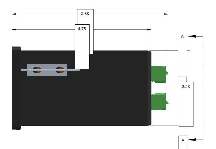
47 Appendix A - Physical Dimensions 47

48 48 Back panel configuration will vary by model. See pages for terminal block connections. Also refer to decal on terminal block for signal identification.
ED3. Digital Encoder Display Page 1 of 13. Description. Mechanical Drawing. Features
 Description Page 1 of 13 The ED3 is an LCD readout that serves as a position indicator or tachometer. The ED3 can display: Speed or position of a quadrature output incremental encoder Absolute position
Vorne Industries. 87/719 Analog Input Module User's Manual Industrial Drive Itasca, IL (630) Telefax (630)
 Telefax (630)") Vorne Industries 87/719 Analog Input Module User's Manual 1445 Industrial Drive Itasca, IL 60143-1849 (630) 875-3600 Telefax (630) 875-3609 . 3 Chapter 1 Introduction... 1.1 Accessing Wiring Connections
Vorne Industries 87/719 Analog Input Module User's Manual 1445 Industrial Drive Itasca, IL 60143-1849 (630) 875-3600 Telefax (630) 875-3609 . 3 Chapter 1 Introduction... 1.1 Accessing Wiring Connections
Noise Detector ND-1 Operating Manual
 Noise Detector ND-1 Operating Manual SPECTRADYNAMICS, INC 1849 Cherry St. Unit 2 Louisville, CO 80027 Phone: (303) 665-1852 Fax: (303) 604-6088 Table of Contents ND-1 Description...... 3 Safety and Preparation
Registers type ILR7XX and ILR7XXT
 Badger Meter Europa GmbH Registers type ILR7XX and ILR7XXT INSTALLATION AND OPERATION MANUAL May 2018 Contents Page 1. Basic safety recommendations... 1 2. Register operation... 3 2.1. Normal operation...
Revision 1.2d
 Specifications subject to change without notice 0 of 16 Universal Encoder Checker Universal Encoder Checker...1 Description...2 Components...2 Encoder Checker and Adapter Connections...2 Warning: High
ORM0022 EHPC210 Universal Controller Operation Manual Revision 1. EHPC210 Universal Controller. Operation Manual
 ORM0022 EHPC210 Universal Controller Operation Manual Revision 1 EHPC210 Universal Controller Operation Manual Associated Documentation... 4 Electrical Interface... 4 Power Supply... 4 Solenoid Outputs...
Operating instructions Electronic preset counter Type series 717
 Operating instructions Electronic preset counter Type series 717 1. Description 5.98.3_gb 6-digit adding/subtracting counter with two presets Very bright 8mm high LED display Counting and preset range
THE ASTRO LINE SERIES GEMINI 5200 INSTRUCTION MANUAL
 THE ASTRO LINE SERIES GEMINI 5200 INSTRUCTION MANUAL INTRODUCTION The Gemini 5200 is another unit in a multi-purpose series of industrial control products that are field-programmable to solve multiple
Model IQ4-PC User Manual Revision Date:
 Basic Specifications Supply Volts 230V 50/60Hz ±15% 115V 50/60Hz ±15% 24V DC (isolated) ±15% Power Consumption Max. 3VA (IQ4-PC-R0) Max. 6VA (IQ4-PC-R2-PSI24-RT) Operating Temperature -5 ~ +60 C Operating
FRQM-2 Frequency Counter & RF Multimeter
 FRQM-2 Frequency Counter & RF Multimeter Usage Instructions Firmware v2.09 Copyright 2007-2011 by ASPiSYS Ltd. Distributed by: ASPiSYS Ltd. P.O.Box 14386, Athens 11510 (http://www.aspisys.com) Tel. (+30)
FlexiScan. Impro FlexiScan 4-Channel Controller INSTALLATION MANUAL
 MODEL NUMBER: HCM991-0-0-GB-XX FlexiScan SPECIFICATIONS Impro FlexiScan 4-Channel Controller INSTALLATION MANUAL Working Environment... Security... Input Voltage... The Impro FlexiScan is designed to work
TABLE OF CONTENTS. Instructions:
 TABLE OF CONTENTS Instructions: 1 Overview 1 2 Main technical parameters 1 3 Display and keyboard 2 3.1 Display Window 2 3.2 Indicator 4 4. Operation 4 4.1 Power 4 4.2 Zero 4 Modified 4 4.3 Modified 4
Quick Setup Guide for IntelliAg Model NTA
 STEP 3: Auto Configuration (identifies sensors connected to each module) Auto config is performed at the factory, but may need to be done in the field as changes are made to the system or if options are
Part No. ENC-LAB01 Users Manual Introduction EncoderLAB
 PCA Incremental Encoder Laboratory For Testing and Simulating Incremental Encoder signals Part No. ENC-LAB01 Users Manual The Encoder Laboratory combines into the one housing and updates two separate encoder
THE ASTRO LINE SERIES GEMINI 4000 INSTRUCTION MANUAL
 THE ASTRO LINE SERIES GEMINI 4000 INSTRUCTION MANUAL INTRODUCTION The Gemini 4100 and 4200 are both units in a multi-purpose series of industrial control units that are field-programmable to solve multiple
Single Axis Position Controller
 SERIES P9511 Single Axis Position Controller Compact Construction Simple Go-to operation Integrated Relay Output Integrated Mains Power Supply ELEKTRO-TRADING sp. Z o.o. 44-109 Gliwice, ul. Mechaników
Figure 1: Standard 906 Sensor and Pulser Disc. Figure 2: Standard 906 Sensor and Pulser Wrap
 Description: The TR5000 is a Full Logic Control Process ratemeter that can display up to three separate values of rate and compare them to programmable set points. Rates A & B can be programmed by the
ST-4000 SIGNAL LEVEL METER
 ST-4000 SIGNAL LEVEL METER Table of Contents Features / Specifications.... 1 Keypad Illustration....... 2 Keypad Controls.... 2 Getting Started: Powering the Meter.... 3 Quick Use Instructions.. 3 Main
AES-402 Automatic Digital Audio Switcher/DA/Digital to Analog Converter
 Broadcast Devices, Inc. AES-402 Automatic Digital Audio Switcher/DA/Digital to Analog Converter Technical Reference Manual Broadcast Devices, Inc. Tel. (914) 737-5032 Fax. (914) 736-6916 World Wide Web:
Quick Start Function Summary Instructions for ASHCROFT GC52 Differential Pressure Transmitter Version 6.03 Rev. B
 Quick Start Function Summary Instructions for ASHCROFT GC52 Differential Pressure Transmitter Version 6.03 Rev. B (See Complete I&M Manual for Further Detail) LOOK FOR THIS AGENCY MARK ON OUR PRODUCTS
THE ASTRO LINE SERIES GEMINI 1000/2000 INSTRUCTION MANUAL
 THE ASTRO LINE SERIES GEMINI 1000/2000 INSTRUCTION MANUAL INTRODUCTION The Gemini 1000 and 2000 are both units in a multi-purpose series of industrial control units that are field-programmable to solve
UNIVERSAL DIGITAL METER DC Volts and Amps AC RMS Volts and Amps Thermocouples and RTDs Process Signals Strain Gauge and Load Cell
 99 Washington Street Melrose, MA 02176 Fax 781-665-0780 TestEquipmentDepot.com UNIVERSAL DIGITAL METER DC Volts and Amps AC RMS Volts and Amps Thermocouples and RTDs Process Signals Strain Gauge and Load
IEFIS G3 Inputs, outputs and Alarms
 IEFIS G3 Inputs, outputs and Alarms Document version: 2, May 2016 User manual on the use and configuration of the analog and digital inputs and digital outputs as well as Alarm setup and use. Related equipement:
MG-XV operating instruction. Measuring of norm signals, 4-8-digit. Panel instrument type MG-BV Construction instrument type MG-AV
 MG-XV operating instruction Measuring of norm signals, 4-8-digit Panel instrument type MG-BV Construction instrument type MG-AV Contents 1. Brief description... 3 2. Safety instructions... 3 2.1. Proper
16-BIT LOAD CELL/DUAL STATUS INPUT
 16-BIT LOAD CELL/DUAL STATUS INPUT On-board Excitation. +5VDC, (120mA). State-of-the-art Electromagnetic Noise Suppression Circuitry. Ensures signal integrity even in harsh EMC environments. Optional Excitation
MT03A Electronic converter for flow rate transmitters
 Instructions manual MT03A Electronic converter for flow rate transmitters The art of measuring R-MI-MT03A Rev.: 0 English version PREFACE Thank you for choosing a Tecfluid S.A product. This instruction
Quick Setup Guide for IntelliAg Model CTA
 STEP 3: Auto Configuration (identifies sensors connected to each module) Auto config is performed at the factory, but may need to be done in the field as changes are made to the system or if options are
AES-404 Digital Audio Switcher/DA/Digital to Analog Converter
 Broadcast Devices, Inc. AES-404 Digital Audio Switcher/DA/Digital to Analog Converter Technical Reference Manual Broadcast Devices, Inc. Tel. (914) 737-5032 Fax. (914) 736-6916 World Wide Web: www.broadcast-devices.com
LAUREL ELECTRONICS, INC.
 LAUREL ELECTRONICS, INC. Laureate Digital Panel Meter for Process, Strain & Potentiometer Follower Signals Features Selectable ±0.2, ±2, ±20, ±200, ±300 & ±600 Vdc voltage ranges Selectable ±2, ±20, ±200
Electronic converter for level transmitters MT03L Instructions manual
 Electronic converter for level transmitters MT03L Instructions manual R-MI-MT03L Rev.: 1 English version PREFACE Thank you for choosing the MT03L converter from MT03 series of Tecfluid S.A. This instruction
CARLO GAVAZZI Automation Components
 CARLO GAVAZZI Automation Components UDM 35/40 Digital Panel Meter Programming Guide Index Description 2 Programming Fundamentals 3 Access to Programming Mode/Password Protection 4 Programming 5-18 Inputs
ST-4000D SIGNAL LEVEL METER
 ST-4000D SIGNAL LEVEL METER Rev 100606 Table of Contents Features / Specifications.... 1 Keypad Illustration....... 2 Keypad Controls.... 2 Getting Started: Powering the Meter...... 3 Quick Use Instructions.....
Operating Instructions
 CNTX Contrast sensor Operating Instructions CAUTIONS AND WARNINGS SET-UP DISTANCE ADJUSTMENT: As a general rule, the sensor should be fixed at a 15 to 20 angle from directly perpendicular to the target
Model 1476-C SuperQuad HR
 Model 1476-C SuperQuad HR Installation and Operating Instructions Table of Contents Page Table of Content... 2 System Description... 3 Features... 3 Installation... 4 Internal Setups... 4 Connections...
3214NXT. Service Manual. IMPORTANT: Fill in Pertinent Information on Page 3 for Future Reference
 3214NXT Service Manual IMPORTANT: Fill in Pertinent Information on Page 3 for Future Reference Table of Contents Job Specification Sheet 3 Timer Operation 4 System Operation in Service 6 Flow in a Four-Unit
AX 345. Process Indicator with Two Analogue Inputs, Calculations and Programmable Analogue Output. Operating Instructions for Model AX 346
 control motion interface motrona GmbH Zwischen den Wegen 32 78239 Rielasingen - Germany Tel. +49 (0)7731-9332-0 Fax +49 (0)7731-9332-30 info@motrona.com www.motrona.com AX 346 Process Indicator with Two
LAUREL. Laureate Digital Panel Meter for Load Cell & Microvolt Input ELECTRONICS, INC. Features. Description
 Description LAUREL ELECTRONICS, INC. Features Laureate Digital Panel Meter for Load Cell & Microvolt Input 20, 50, 100, 250 & 500 mv ranges Span adjust from 0 to ±99,999, zero adjust from -99,999 to +99,999
Triple RTD. On-board Digital Signal Processor. Linearization RTDs 20 Hz averaged outputs 16-bit precision comparator function.
 Triple RTD SMART INPUT MODULE State-of-the-art Electromagnetic Noise Suppression Circuitry. Ensures signal integrity even in harsh EMC environments. On-board Digital Signal Processor. Linearization RTDs
EDL8 Race Dash Manual Engine Management Systems
 Engine Management Systems EDL8 Race Dash Manual Engine Management Systems Page 1 EDL8 Race Dash Page 2 EMS Computers Pty Ltd Unit 9 / 171 Power St Glendenning NSW, 2761 Australia Phone.: +612 9675 1414
OPERATION AND MAINTENANCE
 BAS MS/TP Enabled OPERATION AND MAINTENANCE An Company Contents Powering Up For The First Time... 3 Setting MSTP Communication Parameters... 4 Changing the MSTP Address... 4 Changing the BACNET ID... 5
Troubleshooting CS800/LC900 Bikes
 Troubleshooting CS800/LC900 Bikes CS800/900LC Bike Troubleshooting Entering the Maintenance Mode 15 Touch Screen: The Maintenance Mode is designed to help the tech determine certain faults in the upper
ProVu PD6000 Process Meter
 Congratulations on your purchase of the ProVu PD6000 process meter! This quick start guide will briefly describe some of the common setup procedures for this meter. This guide includes: Basic Wiring for
Signal Conditioners. Highlights. Battery powered. Line powered. Multi-purpose. Modular-style. Multi-channel. Charge & impedance converters
 Signal Conditioners Highlights Battery powered Line powered Multi-purpose Modular-style Multi-channel Charge & impedance converters Industrial charge amplifiers & sensor simulators PCB Piezotronics, Inc.
American DJ. Show Designer. Software Revision 2.08
 American DJ Show Designer Software Revision 2.08 American DJ 4295 Charter Street Los Angeles, CA 90058 USA E-mail: support@ameriandj.com Web: www.americandj.com OVERVIEW Show Designer is a new lighting
Digital differential Pressure switch Model DPS Instruction manual
 Digital differential Pressure switch Model DPS Instruction manual DPSeng_rev2 September 09 MECAIR S.r.l. Diaphragm Valves and Electronic Controls for Dust Collector Filters Via per Cinisello 97 20054 Nova
Panel cutout required: 1.772" x 3.622" (45mm x 92mm) 1.76" (45mm) 2.45" (62mm) 3.20" (81mm) 3.60" (91mm) 0.59" (15mm) Special Features
 1.76 (45mm) 2.45 (62mm) 3.20 (81mm) 3.60 (91mm) 0.59 (15mm) Special Features") NEMA4X, IP65 Front Bezel Meter with Relays Option RELAY2 RELAY1 24V OUT POWER 4 3 2 1 6 5 2 1 2 1 NO NC COM NO NC COM RTD TC P P RTD 3 4 1 2 5 TC 6 SWITCH Rear View Gasket APM765 Panel Meter Description
NEMA4X, IP65 Front Bezel Meter with Relays Option RELAY2 RELAY1 24V OUT POWER 4 3 2 1 6 5 2 1 2 1 NO NC COM NO NC COM RTD TC P P RTD 3 4 1 2 5 TC 6 SWITCH Rear View Gasket APM765 Panel Meter Description
16 Stage Bi-Directional LED Sequencer
 16 Stage Bi-Directional LED Sequencer The bi-directional sequencer uses a 4 bit binary up/down counter (CD4516) and two "1 of 8 line decoders" (74HC138 or 74HCT138) to generate the popular "Night Rider"
Description. Specifications and Ordering Information 1900/27 Vibration Monitor
 R Specifications and Ordering Information 1900/27 Vibration Monitor Description The 1900/27 is a single-channel, stand-alone, locally mounted vibration monitor. It can be used as a stand-alone machinery
imso-104 Manual Revised August 5, 2011
 imso-104 Manual Revised August 5, 2011 Section 1 Getting Started SAFETY 1.10 Quickstart Guide 1.20 SAFETY 1.30 Compatibility 1.31 Hardware 1.32 Software Section 2 How it works 2.10 Menus 2.20 Analog Channel
Global Water Instrumentation, Inc.
 Global Water Instrumentation, Inc. 151 Graham Road P.O. Box 9010 College Station, TX 77842-9010 T: 800-876-1172 Int l: (979) 690-5560, F: (979) 690-0440 E-mail : globalw@globalw.com FC220 Flow Monitor
EMO-500. Opera on & Installa on Manual TWO-COMPONENT RATIO MONITOR. Rev. 6
 TWO-COMPONENT RATIO MONITOR Operaon & Installaon Manual Rev. 6 Table of Contents Safety Definitions and Information... 4 Unpacking... 4 Quick Start Guide... 5 Connect to Flow Transmitters... 5 Connect
Installation and User Guide 458/CTR8 8-Channel Ballast Controller Module
 Installation and User Guide 458/CTR8 8-Channel Ballast Controller Module Helvar Data is subject to change without notice. www.helvar.com i Contents Section Page Introduction 1 Installation 2 1. Attach
TriLIN Program Utility TPU_ TriLIN Programming Manual
 Program Utility TPU_2.8.2 TriLIN Programming Manual 1. Programming the electronics a. Tool necessary Power supply 12-32 V DC Computer with appropriate USB port and a Windows Operating System (We recommend
Preset Counters. X e. X d 6.92 X. 0. IP khz Batch. LCD Preset Counters 1, 2, 4 or 6 Presets. Multifunction. Fast and user-friendly
 The Codix 923/924 can be used universally. As a preset pulse counter, tachometer or preset timer with up to 6 presets it is able to solve a very wide range of control and monitoring tasks in every application.
Operating Instructions (ed. 5.97) Electronic Preset Counter Type Series 904
 Electronic Preset Counter Type Series 904") Operating Instructions 3.96.3 (ed. 5.97) Electronic Preset Counter Type Series 904 1. Description 6 digit preset counter, 2 presets, add./subtr. bright 2-line LCD display with symbols for activated outputs
Operating Instructions 3.96.3 (ed. 5.97) Electronic Preset Counter Type Series 904 1. Description 6 digit preset counter, 2 presets, add./subtr. bright 2-line LCD display with symbols for activated outputs
3200NT System 14. Service Manual. IMPORTANT: Fill in Pertinent Information on Page 3 for Future Reference
 3200NT System 14 Service Manual IMPORTANT: Fill in Pertinent Information on Page 3 for Future Reference Table of Contents Job Specification Sheet... 3 Timer Operation... 4 System Operation In Service...
ASNT_PRBS20B_1 18Gbps PRBS7/15 Generator Featuring Jitter Insertion, Selectable Sync, and Output Amplitude Control
 ASNT_PRBS20B_1 18Gbps PRBS7/15 Generator Featuring Jitter Insertion, Selectable Sync, and Output Amplitude Control Broadband frequency range from 20Mbps 18.0Gbps Minimal insertion jitter Fast rise and
SCALE & WEIGHT DISPLAYS
 The MICRO SERIES SCALE & WEIGHT DISPLAYS LARGE DIGIT MODELS Mighty-5S DPM MODELS Micro-S & Mighty-1S Mighty-1S Micro-S ELECTRO-NUMERICS, INC. Introduction The Electro-Numerics family of Digital Panel Meters
800 Displaying Series Flowmeter
 TECHNICAL PRODUCT INSTRUCTION SHEET 800 Displaying Series Flowmeter OVERVIEW The principle of operation is very simple. A jet of liquid is directed at a free running Pelton wheel turbine in a specially
TUSKIN Equipment Corporation
 TUSKIN Equipment Corporation TC-101 Liquid Color Metering System Operation & Maintenance Manual Warning: Read instructions carefully before attempting to install, operate or service the Tuskin Metering
USER MANUAL FOR THE ANALOGIC GAUGE FIRMWARE VERSION 1.0
 by USER MANUAL FOR THE ANALOGIC GAUGE FIRMWARE VERSION 1.0 www.aeroforcetech.com Made in the USA! WARNING Vehicle operator should focus primary attention to the road while using the Interceptor. The information
USER MANUAL FOR THE ANALOGIC GAUGE FIRMWARE VERSION 1.1
 by USER MANUAL FOR THE ANALOGIC GAUGE FIRMWARE VERSION 1.1 www.aeroforcetech.com Made in the USA! WARNING Vehicle operator should focus primary attention to the road while using the Interceptor. The information
Model 5250 Five Channel Digital to Analog Video Converter Data Pack
 Model 5250 Five Channel Digital to Analog Video Converter Data Pack E NSEMBLE D E S I G N S Revision 3.1 SW v2.0.1 This data pack provides detailed installation, configuration and operation information
QRF5000 MDU ENCODER. Data Sheet
 Radiant Communications Corporation 5001 Hadley Road South Plainfield NJ 07080 Tel (908) 757-7444 Fax (908) 757-8666 WWW.RCCFIBER.COM QRF5000 MDU ENCODER Data Sheet Version 1.1 1 Caution Verify proper grounding
BER MEASUREMENT IN THE NOISY CHANNEL
 BER MEASUREMENT IN THE NOISY CHANNEL PREPARATION... 2 overview... 2 the basic system... 3 a more detailed description... 4 theoretical predictions... 5 EXPERIMENT... 6 the ERROR COUNTING UTILITIES module...
Transmitter Interface Program
 Transmitter Interface Program Operational Manual Version 3.0.4 1 Overview The transmitter interface software allows you to adjust configuration settings of your Max solid state transmitters. The following
Application Note 11 - Totalization
 Application Note 11 - Totalization Using the TrendView Recorders for Totalization The totalization function is normally associated with flow monitoring applications, where the input to the recorder would
BooBox Flex. OPERATING MANUAL V1.1 (Feb 24, 2010) 6 Oakside Court Barrie, Ontario L4N 5V5 Tel: Fax:
 6 Oakside Court Barrie, Ontario L4N 5V5 Tel: Fax:") BooBox Flex OPERATING MANUAL V1.1 (Feb 24, 2010) 6 Oakside Court Barrie, Ontario L4N 5V5 Tel: 905-803-9274 Fax: 647-439-1470 www.frightideas.com Connections The BooBox Flex is available with Terminal Blocks
BooBox Flex OPERATING MANUAL V1.1 (Feb 24, 2010) 6 Oakside Court Barrie, Ontario L4N 5V5 Tel: 905-803-9274 Fax: 647-439-1470 www.frightideas.com Connections The BooBox Flex is available with Terminal Blocks
STD-525T PRECISION TIMER
 FN:STD525TM1.DOC STD-525T PRECISION TIMER DESCRIPTION The STD-525T Precision Timer measures and displays accurate elapsed time in minutes, seconds, tenths of seconds, and hundredths of seconds (MM.SS.TH)
PB-507. Advanced Analog & Digital Electronic Design Workstation Instruction Manual. Revision: 2/2014
 PB-507 Advanced Analog & Digital Electronic Design Workstation Instruction Manual Revision: 2/2014 Test Equipment Depot - 800.517.8431-99 Washington Street Melrose, MA 02176 TestEquipmentDepot.com 1 1
TABLE OF CONTENTS SPECIFICATIONS...1 MOUNTING...3 WIRING...4 THEORY OF OPERATION...6 MILIVOLT INPUT OPTION JUMPER SELECTIONS...7
 TABLE OF CONTENTS SPECIFICATIONS...1 MOUNTING...3 WIRING...4 THEORY OF OPERATION...6 MILIVOLT INPUT OPTION JUMPER SELECTIONS...7 FRONT PANEL OPERATIONS...8 PROGRAMMING FLOW CHART...8 DEFINITIONS OF MENU
Quick Operation Guide of LTN7700/7600 Series NVR
 Quick Operation Guide of LTN7700/7600 Series NVR UD.6L0202B0042A02 Thank you for purchasing our product. If there is any question or request, please do not hesitate to contact dealer. This manual is applicable
Specifications. End-Point Linearity - ±5% F.S., when used with HACO SCR-speed control
 Specifications Model 552 Catalog No. Model Power 55-0665 552 115 VAC, 50-60 Hz 55-0673 552A 230 VAC, 50-60 Hz Input - Single-ended, DC coupled 0 to +10V. Signal source can be Floating (not referenced to
Veeder-Root brand Series C628 Dual Preset Counter (C628-8XXX) Technical Manual
 Technical Manual") Introduction Your Veeder-Root brand C628 Dual Preset Counter is one model in a family of 1/8 DIN units which offers breakthrough display technology as well as easy-to-program single-line parameters. Designed
Introduction Your Veeder-Root brand C628 Dual Preset Counter is one model in a family of 1/8 DIN units which offers breakthrough display technology as well as easy-to-program single-line parameters. Designed
SNG-2150C User s Guide
 SNG-2150C User s Guide Avcom of Virginia SNG-2150C User s Guide 7730 Whitepine Road Revision 001 Richmond, VA 23237 USA GENERAL SAFETY If one or more components of your earth station are connected to 120
PulseFlow FP100 Pulse to 4 20mA Flow Converter (Flow Rate Transmitter / Totalizer / Indicator)
") PulseFlow FP100 Pulse to 4 20mA Flow Converter (Flow Rate Transmitter / Totalizer / Indicator) Submeter Solutions, Inc. PulseFlow FP100 Submeter Solutions, Inc., 800-64METER Page 1 Table of Contents: Installation
PulseFlow FP100 Pulse to 4 20mA Flow Converter (Flow Rate Transmitter / Totalizer / Indicator) Submeter Solutions, Inc. PulseFlow FP100 Submeter Solutions, Inc., 800-64METER Page 1 Table of Contents: Installation
Installation / Set-up of Autoread Camera System to DS1000/DS1200 Inserters
 Installation / Set-up of Autoread Camera System to DS1000/DS1200 Inserters Written By: Colin Langridge Issue: Draft Date: 03 rd July 2008 1 Date: 29 th July 2008 2 Date: 20 th August 2008 3 Date: 02 nd
1.2 General Description
 Note: It is suggested that the foldout at the back of the manual be extended when using this manual. The FOLDOUT, a front view of the AM-48, defines the numbers of the switches which are used to identify
SC26 Magnetic Field Cancelling System
 SPICER CONSULTING SYSTEM SC26 SC26 Magnetic Field Cancelling System Makes the ambient magnetic field OK for electron beam tools in 300 mm wafer fabs Real time, wideband cancelling from DC to > 9 khz fields
AES Channel Digital/Analog Audio Switcher/DA/Digital to Analog Converter
 Broadcast Devices, Inc. AES-408 8 Channel Digital/Analog Audio Switcher/DA/Digital to Analog Converter Technical Reference Manual Broadcast Devices, Inc. Tel. (914) 737-5032 Fax. (914) 736-6916 World Wide
DCP100 Digital Control Programmer Specifications
 DCP100 Digital Control Programmer Specifications EN01-6028 October 1996 Overview The DCP100 is a microprocessor based 1 /4 DIN programmer/controller for process variable versus time control of temperature,
ZIRCONIA OXYGEN ANALYZER CONVERTER
 Service Manual ZIRCONIA OXYGEN ANALYZER CONVERTER TYPE: ZKM INZ-TN5A0845b-E Contents 1. GENERAL...1 1.1 ZKM1 Internal constitution...1 1.2 ZKM2 Internal constitution...1 1.3 Description on display/setting
Preset counters, electronic
 The multifunction preset counters Codix 923 / 924 can be used universally. These preset pulse counters, tachometers or preset timers with up to 6 presets can solve a wide variety of control and monitoring
(Cat. No IJ, -IK)
") (Cat. No. 1771-IJ, -IK) Product Data The Encoder/Counter Module Assembly (cat. no. 1771-IJ or 1771-IK) maintains a count, independent of the processor, of input pulses that may typically originate from
(Cat. No. 1771-IJ, -IK) Product Data The Encoder/Counter Module Assembly (cat. no. 1771-IJ or 1771-IK) maintains a count, independent of the processor, of input pulses that may typically originate from
DIVERSITY DVB-T RECEIVER (DDR)
") User s Manual The most important thing we build is trust. DIVERSITY DVB-T RECEIVER (DDR) Cobham Surveillance GMS Products 1916 Palomar Oaks Way Ste 100 Carlsbad, CA 92008 100-M0062X2 T: 760-496-0055 05/15/09
User s Manual The most important thing we build is trust. DIVERSITY DVB-T RECEIVER (DDR) Cobham Surveillance GMS Products 1916 Palomar Oaks Way Ste 100 Carlsbad, CA 92008 100-M0062X2 T: 760-496-0055 05/15/09
Micro-DCI 53ML5100 Manual Loader
 Micro-DCI 53ML5100 Manual Loader Two process variable inputs Two manually controlled current outputs Multiple Display Formats: Dual Channel Manual Loader, Single Channel Manual Loader, Manual Loader with
2002 Martin Professional A/S, Denmark.
 Freekie user manual 2002 Martin Professional A/S, Denmark. All rights reserved. No part of this manual may be reproduced, in any form or by any means, without permission in writing from Martin Professional
BE1-81O/U Frequency Protection. Washington State University Hands-On Relay School.
 Frequency Protection Washington State University Hands-On Relay School www.basler.com Relay Benefits As many as four independent, adjustable frequency setpoints and time delays Each setpoint has output
ANALOG I/O MODULES AD268 / DA264 / TC218 USER S MANUAL
 UM-TS02 -E026 PROGRAMMABLE CONTROLLER PROSEC T2-series ANALOG I/O MODULES AD268 / DA264 / TC218 USER S MANUAL TOSHIBA CORPORATION Important Information Misuse of this equipment can result in property damage
QUICK START GUIDE FOR DEMONSTRATION CIRCUIT /12/14 BIT 10 TO 105 MSPS ADC
 LTC2280, LTC2282, LTC2284, LTC2286, LTC2287, LTC2288 LTC2289, LTC2290, LTC2291, LTC2292, LTC2293, LTC2294, LTC2295, LTC2296, LTC2297, LTC2298 or LTC2299 DESCRIPTION Demonstration circuit 851 supports a
COMPOSITE VIDEO LUMINANCE METER MODEL VLM-40 LUMINANCE MODEL VLM-40 NTSC TECHNICAL INSTRUCTION MANUAL
 COMPOSITE VIDEO METER MODEL VLM- COMPOSITE VIDEO METER MODEL VLM- NTSC TECHNICAL INSTRUCTION MANUAL VLM- NTSC TECHNICAL INSTRUCTION MANUAL INTRODUCTION EASY-TO-USE VIDEO LEVEL METER... SIMULTANEOUS DISPLAY...
This document is a reference document that shows the menus in the 5500sc, 9610sc and 9611sc analyzers. There are 3 top-level menus:
 Controller menus 5500sc, 9610sc and 9611sc analyzers DOC273.53.80566 Introduction This document is a reference document that shows the menus in the 5500sc, 9610sc and 9611sc analyzers. There are 3 top-level
ZU 251. Incremental Counter Module With Analogue Output and Serial Interface. Operating Instructions. control motion interface
 control motion interface motrona GmbH Zwischen den Wegen 32 78239 Rielasingen - Germany Tel. +49 (0)7731-9332-0 Fax +49 (0)7731-9332-30 info@motrona.com www.motrona.com ZU 251 Incremental Counter Module
User Manual CC DC 24 V 5A. Universal Control Unit UC-1-E. General Information SET. Universal Control Unit UC-1 Of Central Lubrication PAUSE CONTACT
 Universal Control Unit UC-1-E User Manual General Information Universal Control Unit UC-1 Of Central Lubrication CC DC 24 V 5A / M 15 SL /MK 31 M Z 30 General Information Contents Universal Control Unit
Multifunction devices
 devices devices devices, electronic Type Page LED multifunction displays pulse, frequency, time (DC) Codix 524 240 pulse, frequency, time (AC+DC) Codix 544 243 LCD multifunction preset counters 1 or 2
Special Applications Modules
 (IC697HSC700) datasheet Features 59 1 IC697HSC700 a45425 Single slot module Five selectable counter types 12 single-ended or differential inputs TTL, Non-TTL and Magnetic Pickup input thresholds Four positive
FS340 and FS641. High Performance Low Cost Controller for Flying Shears and Saws
 control motion interface motrona GmbH Zwischen den Wegen 32 78239 Rielasingen - Germany Tel. +49 (0)7731-9332-0 Fax +49 (0)7731-9332-30 info@motrona.com www.motrona.com FS340 and FS641 High Performance
MENU EXECUTE Shiloh Road Alpharetta, Georgia (770) FAX (770) Toll Free
 FAX (770) Toll Free") Instruction Manual Model 2016-1250 Downconverter May 2009 Rev A F=2501.750 G=+25.0 MENU MODEL 2016 DOWNCONVERTER CROSS TECHNOLOGIES INC. ALARM REMOTE POWER EXECUTE Data, drawings, and other material contained
Instruction Manual Model 2016-1250 Downconverter May 2009 Rev A F=2501.750 G=+25.0 MENU MODEL 2016 DOWNCONVERTER CROSS TECHNOLOGIES INC. ALARM REMOTE POWER EXECUTE Data, drawings, and other material contained
1 Output 1 operation. 3 Pressure unit display. 4 Main display Large 4-character LCD display. 5 Sub-display Small 4-character LCD display.
 ure Sensor DP-100 Series INSTRUCTI MANUAL High-performance Digital Display For use outside Japan MEUML-DP100 V1.1 Thank you for purchasing products from Panasonic Electric Works SUNX Co., Ltd. Please read
BE3-GPR GENERATOR PROTECTIVE RELAY
 BE3-GPR GENERATOR PROTECTIVE RELAY Behind-the-Panel Mounting Semi-flush Mounting Basler Electric s BE3-GPR generator protective relay offers multiple protective features in a single package. Its microprocessor-based