STATE-OF-THE-ART ELECTRON GUNS AND INJECTOR DESIGNS FOR ENERGY RECOVERY LINACS (ERL)
|
|
|
- Harvey Brown
- 5 years ago
- Views:
Transcription
1 STATE-OF-THE-ART ELECTRON GUNS AND INJECTOR DESIGNS FOR ENERGY RECOVERY LINACS (ERL) Alan Todd Advanced Energy Systems P.O. Box 7455, Princeton, NJ , U.S.A. Corresponding author: Alan Todd Phone: ; FAX: ; alan_todd@mail.aesys.net ABSTRACT A key technology issue of energy recovery linac (ERL) high-power free-electron laser (FEL) and fourth generation light sources is the demonstration of reliable, high-brightness, highpower injector operation. Ongoing programs that target up to 0.5 Ampere injector performance at emittance values consistent with the requirements of these applications, are described. There are three approaches that could deliver the specified performance. These are DC photocathode guns with superconducting RF (SRF) booster cryomodules, high-current normal-conducting RF (NCRF) photoinjectors that may also use SRF boosters, and SRF photocathode guns and boosters. The achieved performance at existing ERL facilities, the status of ongoing source development programs, and the proposed parameters of the injectors for planned ERL facilities are described and compared. As examples, we concentrate on three high-current injectors being developed by Advanced Energy Systems (AES) with collaborators at the Thomas Jefferson National Accelerator Facility (JLAB), Los Alamos (LANL) and Brookhaven (BNL) National Laboratories. PACS: w, AC, Ja, Ha Keywords: Photoinjector, Electron Gun, DC Gun, High-Average-Current, Superconducting Radio Frequency (SRF), Energy Recovery Linac (ERL).
2 1. INTRODUCTION Although the ERL concept had been in existence for many years [1,2,3,4], the spark that spawned many of the ERL devices discussed below was the success of the JLAB ERL IR FEL [5]. Today, there are three active ERL facilities: the JLAB IR FEL Upgrade [6], the ERL FEL at the Japan Atomic Energy Research Institute (JAERI) [7] and the Budker Insitute for Nuclear Physics (BINP) Recuperator at Novosibirsk [8]. Near term ERL facilities under construction include the NSF-funded Cornell [9] and UK Daresbury ERL-Prototype [10] devices. Table 1 lists the principle injector specifications for these and other relevant devices, past, present and future, from which, in Table 2, we will later construct nominal parameter requirements and associated ranges for ERL injectors. The three columns in yellow are the injectors in development at AES that will be discussed in greater detail below. The devices on the left of the table all use DC guns as indicated by Gun Type. These include the active JLAB [6], JAERI [7] and BINP [8] FELs. For the JLAB column, the parameters in parentheses are the values at the wiggler, while the first number in each case is the inferred value after the injector. For BINP and JAERI, the achieved numbers are shown first with projected near-term upgrade values in parentheses. The Cornell ERL [9] injector targets 100 ma average current while the Daresbury ERLP [10] is very similar to the current JLAB device. Both these devices are presently under construction. KEK [11] are developing an ERL concept that is similar to that of Cornell and is not separately listed here. JAERI and BINP use thermionic guns as opposed to the photocathode guns of the other injectors, though JAERI are actively developing a photocathode gun to improve the achievable beam brightness, a key to high-performance for all ERL FELs or light sources. In each case, Gallium Arsenide is the photocathode material of choice for these DC guns. The other listed DC gun and booster consists of a JLAB DC gun and an AES SRF booster that is 1
3 presently being assembled for testing at the JLAB injector test stand beginning in 2006, and which is described in greater detail below. The next three injectors utilize normal-conduction RF (NCRF) guns. It is interesting to appreciate that at 32 ma, the Boeing gun [12,13] shown in Fig. 1 and now retired, which operated at 25% duty factor with a macropulse current of 132 ma, is still the demonstrated high-average-beam-current state-of-the-art despite the recent focus on DC guns. Below, we describe the LANL/AES 700 MHz NCRF Glidcop gun that is in fabrication for thermal testing at LANL in early The nominal operating current for this gun is 100 ma with a 33.3 MHz laser pulse repetition rate (PRF). However, as shown by the figures in parentheses, the same gun, operating at 350 MHz PRF, could, in principle, deliver more than 1 A of average current with the identical thermal load and stress. The LUX project [14] at Lawrence Berkley National Laboratory (LBNL) optimized the cell shaping to design an NCRF gun that delivers improved impedance to lower the thermal loads and stress, thereby permitting the use of OFE copper in place of Glidcop, which can be difficult to braze. The Boeing gun used a Cesium Potassium Antimonide multi-alkaline cathode material. Multi-alkalis are the cathodes of choice for these guns because, as compared to DC guns, the operating vacuum cannot be maintained high enough to permit the use of GaAs. Additionally, for any ERL injector, it is almost mandatory that one use a cathode that responds to green, as opposed to UV, illumination to make the photocathode drive laser tractable, reliable and affordable. The specifics of cathode issues for ERL injectors are addressed in the parallel Reference [15]. Finally, there is growing interest in SRF injectors following the pioneering work of Forschungszentrum Rossendorf, (FZR) [16], albeit at lower current than desired for proposed ERL devices. However, AES is fabricating a MHz half-cell SRF gun, in collaboration with BNL, that is being designed to deliver 0.5 A. In addition to multi-alkalis, 2
4 the novel diamond cathode concept [17] is being considered for this gun. The figures in parenthesis show the significant improvement in the longitudinal beam quality that results from linearizing the longitudinal phase space with a harmonic RF cavity. While this technique can be usefully applied to all injector technologies, none of the other columns includes such optimization. This is one of the three injectors described in more detail below. The final column describes the plans for 4GLS proper as opposed to the ERLP. Here, the desire is to use an SRF gun with a diamond cathode for high-average current operation and most likely an NCRF gun for the alternate high-brightness operation shown in parentheses [18]. The table also indicates what type of booster is planned for each injector unless it is not applicable (N/A). The geometry of the booster in terms of cells per cavity, the power coupling technique and the power level per feed used or planned, whether coaxial (CX) or waveguide (WG), is also shown. In addition to FELs and light sources, there are other ERL and high-current injector applications that have not been specifically included in Table 1. The AES/BNL SRF gun operates at a harmonic of the RHIC frequency and will be a key element of a 0.5 A highcurrent ERL test at BNL in There are two goals for this work [19]: firstly to develop a gun for electron cooling of hadron storage rings such as the Relativistic Heavy Ion Collider (RHIC); and secondly to provide high-intensity electron beams for high-luminosity colliders such as e-rhic and ELIC. Because of the existing RHIC parameters, electron cooling requires 20 nc bunches at 9.4 MHz for an average current of ~200 ma. Hence the ideal injector for this application is not the above 0.5 cell SRF gun, which will however demonstrate the viability of the technology, but rather a 1.5 cell SRF gun without a booster accelerator that accelerates the beam to 5 MeV. The e-rhic collider calls for up to 16 nc 3
5 bunches at MHz for an average current up to 450 ma, and would utilize a similar 1.5 cell gun for the injector. 2. INJECTOR OPTION COMPARISON In looking towards the future, we have combined the Table 1 specification for all the photocathode injectors that plan to operate near or above 100 ma. Table 2 shows the resultant nominal requirements that are being requested for the principal ERL injector parameters, together with an associated range. This table shows that the proposed highcurrent ERL facilities have much in common. It is also clear that there are three injector technologies being seriously considered for ERL facilities, namely: DC, NCRF and SRF guns that will likely be followed by SRF boosters. We do not discuss injector variants and hybrids [20] that utilize coaxial coupling [21,22] or doubly-resonant guns [23,24] that may some day find application in ERL devices. Of the three candidate technologies, the DC gun is the most mature with 10 ma CW already demonstrated at JLAB and 100 ma injectors in fabrication at Cornell and AES/JLAB. Recent Cornell simulations for optimized DC gun configurations show exceptional performance with transverse emittance values significantly lower than 1 µm at the nominal 77 pc charge level [25]. The achievable gradient and voltage with respect to field emission and breakdown may be limited to around 7 MV/m and 500 kv though Cornell plan to stretch these limits experimentally. There will also be a gradient limit set by dark current in these guns. The very high-vacuum capability of the DC gun does lead to a viable cathode option in GaAs, whose performance and lifetime today are limited by ion backbombardment. The 400 C drawn from such a cathode between recesiations [5] corresponds to over an hour of operation at 100 ma, which is not sufficient for ERL facility operation at 4
6 high availability, but is still very promising. Consequently, it appears likely that DC guns coupled with SRF boosters will be capable of delivering the required ERL injector performance. The maximum achievable gradient in CW NCRF guns is limited to around 10 MV/m due to thermal stress limits. There is also an efficiency penalty and associated cost due to the impedance and resistive losses. Achievable vacuum conditions limit visible cathode selection to multi-alkaline materials or diamond amplifiers and raise issues of achievable performance and lifetime. However, we noted that the Boeing injector was still the state-ofthe-art for high-average current gun operation and it serves as a proof-of-concept for NCRF injectors at current levels approaching 100 ma, and with higher beam-loading and PRF, ampere-level operation at the same engineering stress level and beam dynamics performance. The SRF gun, which can, in principle, deliver RF gun performance with DC gun efficiency is the least mature but also the most desirable ERL injector option. The maximum achievable accelerating gradient is likely around 20 MV/m with respect to peak gun fields. It is necessary to demonstrate viable high-average-current choke joint designs and cathode compatibility with the SRF environment, together with a lack of contamination of that environment. As with the NCRF gun, cathode selection is an issue with the diamond amplifier as the preferred approach and multi-alkalis as a backup. However, in contrast to the normal-conducting gun, the SRF gun is expected to have excellent vacuum properties at the cathode surface. At this point we must await experimental demonstration of this option before it can be adopted as a serious candidate for near term facilities. Finally, all the injector technology options must address field limits set by dark current and high-power RF delivery to the accelerating cavities. While high-order modes (HOM), wakefields and beam break up (BBU) instabilities are more issues for the ERL ring accelerating cavities than for the injector cavities, they must still be given serious 5
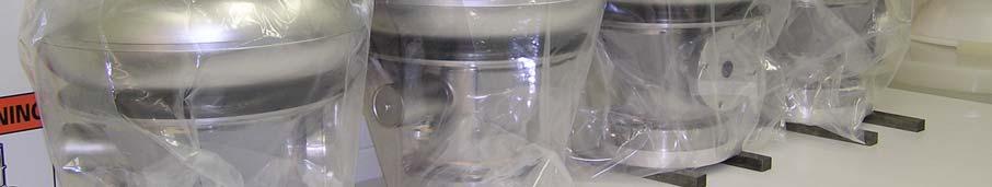
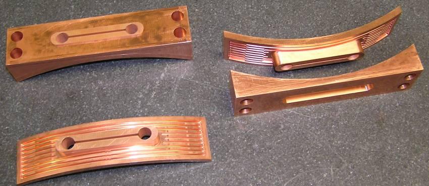
7 consideration in the design process at high beam power. Emittance growth due to space charge and coherent synchrotron radiation (CSR) in mergers and other beam transport elements is also an aspect of the injector design and selection. In the following sections, we describe the design and status of one example of each principle injector option. 3. DC GUN AND SRF BOOSTER The present leading candidate for high-average-current ERL injectors is a DC photocathode gun closely coupled to an SRF booster accelerator. One such device has been designed and fabricated by AES and is presently being assembled at JLAB for testing on their injector test stand. As shown in Fig.2, the device begins with a 500 kv DC gun [26] followed by an emittance compensation solenoid [27]. The electron beam then enters the MHz SRF cryomodule which consists of three single cell fundamental cavities and one MHz third harmonic cavity that accelerate the beam to 7 MeV. The third harmonic cavity is the second cell in the string, whose function is to linearize the longitudinal phase space on exit from the cryostat, as shown by the longitudinal phase space plots in the figure. As was demonstrated with the Boeing injector [28], we have shown that the addition of the longitudinal phase space correction cavity significantly improves the beam quality in these injectors. Specifically at 1 nc or 0.75 A, this configuration can deliver 5.1 microns transverse and 43 kev-psec longitudinal rms emittance at 7 MeV, which is more than adequate for very high-power IR FEL operation. However, due to the recent addition of the harmonic cavity to the actual hardware, we do not list the effect of this correction for 133 pc bunches in Tables 1 and 3, and hence better performance is expected from this device than 6
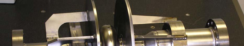
8 indicated. In contrast, the Cornell approach uses five 1300 MHz double-cell booster cavities for their DC gun injector. When every RF bucket is filled with 133 pc, the single cell device provides an average current of 100 ma and an average electron beam power of 700 kw at the 7 MeV injector output. The injector and power couplers have been designed to handle these power levels. The sequence of single cell cavities provides latitude for adjusting the longitudinal phase space through different cavity phasing and ameliorates HOM and wakefield effects driven by high current. The use of MHz means that the injector is compatible with the existing JLAB ERL FEL ring although there are no present plans to install it on that device. Fig. 3 shows four completed single-cell SRF cavities, while Fig. 4 shows the 3 rd harmonic cavity, all minus their helium vessels. Cavity cleaning has begun at JLAB with assembly scheduled for completion by the end of The three fundamental RF power couplers, one per cavity, are designed to deliver 350 kw each. Testing will begin at JLAB in 2006, following the completion of the injector test stand. Initial tests will demonstrate bunch charges up to 1 nc at low PRF, due to initial RF power limitations. Later RF power upgrades should enable 100 ma characterization in NORMAL CONDUCTING RF GUN The second high-power injector approach that is under development at AES is the normal-conducting, CW, photocathode RF electron gun that is shown in Fig. 5. Los Alamos performed the physics and RF design for this 700 MHz, 2½-cell, 3 nc device that delivers 100 ma at a 35 MHz PRF. Higher currents could be delivered without impacting the gun thermal or beam properties, simply by increasing the PRF. A third full cell does not support acceleration but rather serves as a vacuum manifold to permit very high pumping on the gun 7
9 during operation. The crucial issue for this concept is the extremely high-average-power and the peak power densities that result from the resistive losses in the copper of the gun. Two dimensional and three dimensional thermal, stress, and displacement analyses were conducted on the gun design where the effects of temperature and pressure coupled with the RF response were all taken into account. The thermal stresses are such that the gun is manufactured from Glidcop. The total thermal load of the gun is about 720 kw, but analysis indicates the design coolant flow will adequately cool the device. Fig. 6 shows two of the gun cells plated and ready for brazing. One of the ridge loaded waveguide penetrations is visible on cell 3. It also shows the dogbone iris of the power coupler which is a critical thermal and braze point. This gun represents one of the most complex brazing cycles that has ever been attempted. Currently, we are 25% complete on the braze cycle. The gun is scheduled for delivery to Los Alamos for testing in late An existing Los Alamos 1 MW RF test stand will be used to perform a thermal test of the gun in early Beam tests up to about 200 ma CW could be performed in 2006 at reduced accelerating gradient with 1 nc bunches and 200 MHz PRF using the existing LANL RF power, once a preparation chamber and load lock are added to the gun to permit multi-alkali cathode insertion. Addition of a booster, probably SRF and similar to that described above, would enable achieving typical ERL injection energy and performance requirements. 5. SUPERCONDUCTING RF GUN The final option under development at AES in collaboration with BNL, JLAB and FZR is a high-current SRF gun. This gun is being designed and fabricated to deliver 0.5 A to the ERL test ring that is being built at BNL [19]. This high current requires a substantial 8
10 departure from the present FZR 3½-cell design at 1.3 GHz [16]. Firstly, we have adopted a ½-cell gun configuration at the lower frequency of MHz, which is compatible with the RHIC RF frequency, in order to accommodate the higher currents, approaching 0.5 A, required for the RHIC electron cooling rings and the e-rhic collider. Secondly, primarily because of thermal issues, but also for simplicity of fabrication, we determined to utilize a quarter wave choke joint concept [29] that is different from the FZR approach. This is shown to the left in Fig. 7 together with the ½ cell cavity. The details of the output iris and beamtube are not finally set at this time and will change. Thermal and stress analyses of this SRF gun with the quarter wave choke joint have been completed. For 0.5 A operation, the thermal load on the cathode stalk, which is cooled with liquid nitrogen, is between 150 and 180 W, depending on whether a multi-alkali or diamond amplifier cathode is employed. Fig. 8 shows the SRF gun cryostat with a detail of the single cell in the upper left. The cathode preparation chamber is being designed for multi-alkali, diamond and dispenser cathodes. This injector is presently in the final design phase. Delivery to BNL is planned for early Initial gun performance testing will therefore be completed in CONCLUSIONS High-current ERL facilities are being proposed and constructed all over the world. Present facilities operating at the 10 s of ma level will give way to 100 ma and higher current devices. Three technology options exist for the high-current electron injectors these ERL facilities will need. DC guns with SRF boosters are a relatively mature approach and suitable for nearterm deployment. They will likely deliver the required performance at the 100 ma current level and should permit extrapolation towards the Ampere-level. Further, the cathode issue 9
11 is largely solved for this technology at the 100 ma current level with the use of GaAs, although extending the time between recesiations is important. The achievable DC gun accelerating gradient, perhaps limited by dark current, needs to be determined. Normal-conducting RF injectors are the least attractive option for CW operation because of their inefficiency due to resistive wall losses. The achievable gradient is also limited by the resulting thermal constraints. Multi-alkalis are the cathode of choice but suitable lifetime and reliability have yet to be demonstrated. Nevertheless, the Boeing gun, at 32 ma CW, is still the state-of-the-art for high-average current injectors and serves as a proof-of-concept for 100 ma operation. If the cathode, thermal and power coupling issues are solved, these guns can deliver Ampere-level performance and they also remain attractive for lower PRF high-brightness applications as indicated in Table 1 for 4GLS. Superconducting RF injectors are the least mature option and unproven at highaverage current. However, they are the most desirable approach since, in principle, they deliver the better RF gun beam performance at DC gun efficiency levels. They also promise the highest accelerating gradient and thus the most compact option, but must demonstrate a compatible cathode technology and high RF power handling. The performance of three distinct high-current ERL injector technologies, which are under development at AES in partnership with National Laboratories, is listed in Table 3. The impact of harmonic correction, which is important for each technology, is shown in parentheses only for the SRF gun, and each requires further beam tailoring for ERL merging. The 100 ma DC gun with an SRF booster is presently being assembled at JLAB for testing in The normal-conducting gun is in fabrication for delivery to LANL in late It will undergo thermal testing equivalent to beam operation at 1 A in Finally, the SRF gun, which will be installed on the BNL test ERL is in final design. Operation testing of this gun to 0.5 A will occur in
12 ACKNOWLEDGEMENTS The AES injector work is supported by the Naval Sea Systems Command, the Office of Naval Research, the DOD Joint Technology Office and the Missile Defense Agency. We gratefully acknowledge the contributions of the following individuals to the material presented: A. Ambrosio, H. Bluem, V. Christina, M. D. Cole, M. Falletta, D. Holmes, E. Peterson, J. Rathke, T. Schultheiss and R. Wong of AES to the three AES injectors; S. Benson, E. Daly, D. Douglas, F. Dylla, W. Funk, C. Hernandez-Garcia, J. Hogan, P. Kneisel, J. Mammosser, G. R. Neil, L. Phillips, J. Preble, R. Rimmer, C. Rode, T. Siggins, T. Whitlach, M. Wiseman of JLAB, R. Campisi of ORNL, and J. Sekutowicz of DESY to the AES/JLAB DC Gun and Booster; I. Ben-Zvi, A. Burrill, R. Calaga, P. Cameron, X. Chang, H. Hahn, D. Kayran, J. Kewisch, V. Litvinenko, G. McIntyre, A. Nicoletti, J. Rank, J. Scaduto, T. Srinivasan-Rao, K. Wu, A. Zaltsman, Y. Zhao of BNL, D. Janssen of FZR, J. W. Lewellen of ANL, L. Phillips, J. Preble of JLAB, and V. Nguyen- Tuong of Tunnel Dust, to the AES/BNL SRF Gun; P. Colestock, J. P. Kelley, S. Kurennoy, D. Nguyen, S. Russell, W. Reass, D. Rees, D. Schrage, R. Wood of LANL and L. Young of TechSource to the LANL/AES NCRF Gun. Additionally, we wish to thank D. Dowell of LCLS and J. Adamski of Boeing (the Boeing injector and Figure 1), C. Sinclair of Cornell University (the Cornell ERL), R. Rimmer of JLAB (LUX), E. Seddon and M. Dykes of ASTeC, Daresbury, UK (4GLS), N. Vinokurov of BINP, Russia (BINP Recuperator) and E. Minehara of JAERI, Japan (JAERI FEL) for graciously providing information on their described ERL and injector projects. 11
13 FIGURE CAPTIONS Figure MHz, 32 ma Boeing NCRF injector. Figure 2. DC Gun and SRF booster (upper left) with fundamental cavity (upper right). Booster with 3 rd harmonic cavity showing evolution of longitudinal emittance (lower - the vertical scale varies for each phase space plot). Figure 3. Four MHz SRF fundamental cavities. Figure MHz third harmonic SRF cavity. Figure 5. Normal-conducting 2½-cell CW RF gun. Figure 6. NCRF gun cell 2 (upper left) and cell 3 (upper right) plated and ready for brazing. Waveguide irises machined and ready for plating (lower). Figure 7. SRF gun choke joint and ½ cell cavity. Figure 8. SRF gun cryostat with ½ cell cavity detail (upper left). TABLE CAPTIONS Table 1: Summary of parameters for high-current injectors and ERLs. Table 2: ERL injector nominal values and range. Table 3: AES ERL injector parameters. 12
14 REFERENCES [1] M. Tigner, A Possible Apparatus for Electron Clashing-Beam Experiments, Nuovo Cimento 37 (1965) [2] S. O. Schreiber and E. A. Heighway, Double Pass Linear Accelerator Reflexotron, IEEE NS-22 3 (1975) [3] T. I. Smith et al., Development of the SCA/FEL for use in Biomedical and Materials Science Research, NIM A259 (1987) 1-7. [4] D. W. Feldman et al, Energy Recovery in the LANL FEL, NIM A259 (1987) [5] G. R. Neil et al., "Sustained Kilowatt Lasing in a Free-Electron Laser with Same-Cell Energy Recovery," Phys. Rev. Lett. 84 (4) (2000) [6] G. R. Neil et al., The JLAB High-Power ERL Light Source, in this issue of NIM A. [7] E. J. Minehara, Development and Operation of the JAERI ERL (Energy Recovery Linac), ibid. [8] V. P. Bolotin, N. A. Vinokurov et al., ERL at Budker INP, ibid. [9] G. Hoffstaetter et al., ERL Upgrade of an Existing X-ray Facility: CHESS at CESR, Proc. EPAC 2004, ISBN , Lucerne, Switzerland (2004) [10] M. W. Poole and E. A. Seddon, 4GLS and the Prototype Energy Recovery Linac Project at Daresbury, Proc. EPAC 2004, ISBN , Lucerne, Switzerland (2004) [11] E.-S. Kim et al., Design Study for a 205 MeV Energy Recovery Linac Test Facility at the KEK, Proc. EPAC 2004, ISBN , Lucerne, Switzerland (2004)
15 [12] D. H. Dowell et al., Results of the Average Power Laser Experiment Photocathode Injector Test, NIM A356 (1995) [13] D. H. Dowell et al., First Operation of a Photocathode Radio Frequency Gun Injector at High Duty Factor, App. Phys. Lett. 63 (15) (1993) [14] R. A. Rimmer et al., A High-Gradient High-Duty-Factor RF Photo-Cathode Electron Gun, Proc. EPAC 2002, ISSN X, Paris, France (2002) [15] T. Rao et al., in this issue of NIM A. [16] D. Janssen et al., Status of the 3 1/2 Cell Rossendorf Superconducting RF Gun, Proc. FEL 2004, ISBN , Trieste, Italy (2004) [17] T. Rao et al., Diamond Amplifier for Photocathodes, AIP Conf. Proc. 737 (2004) 178. [18] E. A. Seddon and M. W. Poole, 4GLS and the Energy Recovery Linac Prototype Project at Daresbury Laboratory, to appear in Proc. PAC 2005, Knoxville, TN, USA, May 16-20, [19] I. Ben-Zvi and V. Litvinenko, ERLs in High Energy and Nuclear Physics, in this issue of NIM A. [20] S. L. Huang et al., Beam Loading Tests on DC-SC Photoinjector at Peking University, Proc. FEL 2004, ISBN , Trieste, Italy (2004) [21] M. J. de Loos et al., A High-Brightness Pre-accelerated RF-Photo Injector, Proc. EPAC 2002, ISSN X, Paris, France (2002) [22] D. Janssen et al., Axial Power Input in Photocathode Electron Guns, to appear in Proc. PAC 2005, Knoxville, TN, USA, May 16-20, [23] D.H. Dowell et al., A Two-Frequency RF Photocathode Gun, NIM A528 (2004)
16 [24] J. W. Lewellen and J. Noonan, "Field-Emission Cathode Gating for RF Electron Guns," Phys. Rev. ST Accel. Beams 8, (2005) 1-9. [25] I. V. Bazarov and C. K. Sinclair, Multivariate Optimization of a High Brightness DC Gun Photoinjector, Phys. Rev. ST Accel. Beams 8, (2005) [26] C. K. Sinclair, Nucl.Instr.Meth. A318 (1992) [27] B. E. Carlsten, Photoelectric Injector Design Code, Proc. PAC 1989 Chicago, Il, USA, IEEE89CH (1989) [28] D.H. Dowell, T.D. Hayward and A.M. Vetter, Magnetic Pulse Compression Using a Third Harmonic RF Linearizer, Proc. PAC 1995, Dallas, TX, USA, IEEE95CH35843 (2002) [29] V. Nguyen-Tuong, L. Phillips and J. Preble for Tunnel Dust, Inc., priv. comm. 15

17 Figure 1 16
18 MHz 3 rd Harmonic SRF Cell With RF W/G Feed (not shown) Spaceframe DC Gun Cold Box Cold Box 750 MHz Fundamental SRF Cells RF Feed Helium Vessel Emittance Compensation Solenoid (βγ)z z (cm) Figure 2 17


19 Figure 3 18


20 Figure 4 19
21 Vacuum Vacuum Pumps Pumps Vacuum Chamber with Pumps Bucking Solenoid Magnet Cathode Backplate Cooling Focusing Solenoid Magnet Ridge Loaded Waveguide Figure 5 20


22 Figure 6 21
23 SuperFish File Gun 6cm Iris F = MHz Iris diameter = 120 mm Beampipe diameter = 190 mm Frequency = MHz C:\DOCUMENTS AND SETTINGS\KAYRAN\MY DOCUMENTS\ERL\SCGUN_DESIGN\FROM_RAM\RGUN519.AM :18:00 0 Figure 7 22
24 Internal Helium Dewar Top Cover with Facilities Feedthrough Cathode Isolation Valve Cathode Installation Assembly Magnetic and Thermal Shielding Adjustable Supports Vacuum Vessel Power Couplers Beam Line Isolation Valve Cavity Assembly Beam Tube with HOM RF Pickup Figure 8 23
25 DEVICE JLAB AES/JLAB Cornell Daresbury JAERI BINP Boeing LANL/AES LUX AES/BNL 4GLS PARAMETER ERL FEL Injector ERL ERLP ERL ERL FEL Injector Gun Gun Gun/ERL ERL Gun Type DC DC DC DC DC DC NCRF NCRF NCRF SRF SRF(NCRF) Injector and ERL RF Frequency (MHz) PRF (MHz) (83.3) 11.2 (90) (350) (0.001) Charge/Bunch (nc) (1.0) Current (ma) (40) 20 (150) 32(132 Peak) 100 (1050) (0.001) Injector Energy (MeV) (150) Transverse rms Normalized Emittance (µm) < 7 (7) 1.2 < (15) ~ / Longitudinal rms Emittance (kev-psec) 17 (80) (19) RMS Bunch Length (psec) 3.2 (0.35) RMS Energy Spread (%) 0.1 (0.13) < 1 ~ (2.1) ERLP Energy (MeV) 160 N/A (14) N/A N/A N/A 20 ERL Energy Goal (MeV) 200 N/A N/A N/A N/A (1000) Electron Gun DC Gun Voltage (kv) N/A N/A N/A N/A N/A Gun Accelerating Field (MV/m) / 7 / 5 20 / 13 / (TBD) Cathode Material GaAs GaAs GaAs GaAs Thermionic Thermionic CsKSb Multi-Alkali TBD Dia./M-Alk. Dia./M-Alk. Drive Laser FWHM Pulse Length (psec) N/A N/A TBD 10 Laser Wavelength (nm) N/A N/A Laser Power at 5% QE (W) N/A N/A 5 (53) 0.2 / 25 5 (~0) Booster (DC) or Gun (RF) Booster or Gun Type SRF SRF SRF SRF SRF NCRF N/A N/A N/A N/A N/A Geometry (Cavities x Cells) 2 x 5 4 x 1 5 x 2 2 x 9 2 x 1 3 x 1 1 x x 3 1 x x x x 3.5 (TBD) Couplers per Cavity / Type 1 / WG 1/CX:1/WG 2 / CX 2 / WG 1 / CX 2 / WG 2 / WG 3 / WG 2 / CX TBD Coupler Power (kw) (200) TBD Status Operational Assembly Fabrication Fabrication Operational Operational Retired Fabrication Analysis Design/Fab Analysis (Explanation) (At Wiggler) (Upgrade) (Upgrade) (Macropulse) (High PRF) (Correction) (Low PRF) Table 1 24
26 Parameter Value Nominal Range Output Energy (MeV) ~ CW Average Current (ma) ~ Bunch Charge (nc) ~ Transverse rms Normalized Emittance (µm) ~ 1.5 < 1-6 Longitudinal rms Emittance (kev-psec) < Bunch Length (psec) ~ Energy spread (%) at Injection < RF Frequency (MHz) ~ RF Feedthrough Power (kw) < Photocathode Frequency Response Visible Visible Table 2 25
27 DEVICE AES/JLAB LANL/AES AES/BNL PARAMETER Injector Gun Gun/ERL Gun Type DC NCRF SRF RF Frequency (MHz) PRF (MHz) Charge/Bunch (nc) Current (ma) Injector Energy (MeV) Mean Accelerating Gradient (MV/m) 7 / Transverse rms Normalized Emittance (µm) Longitudinal rms Emittance (kev-psec) (19) RMS Bunch Length (psec) RMS Energy Spread (%) (1.7) Table 3 26
Technology Challenges for SRF Guns as ERL Source in View of BNL Work
 Technology Challenges for SRF Guns as ERL Source in View of BNL Work Work being performed and supported by the Collider Accelerator Division of Brookhaven National Labs as well as the Office of Naval Research
TITLE PAGE. Title of paper: PUSH-PULL FEL, A NEW ERL CONCEPT Author: Andrew Hutton. Author Affiliation: Jefferson Lab. Requested Proceedings:
 TITLE PAGE Title of paper: PUSH-PULL FEL, A NEW ERL CONCEPT Author: Andrew Hutton Author Affiliation: Jefferson Lab Requested Proceedings: Unique Session ID: Classification Codes: Keywords: Energy Recovery,
Performance of a DC GaAs photocathode gun for the Jefferson lab FEL
 Nuclear Instruments and Methods in Physics Research A 475 (2001) 549 553 Performance of a DC GaAs photocathode gun for the Jefferson lab FEL T. Siggins a, *, C. Sinclair a, C. Bohn b, D. Bullard a, D.
SLAC R&D Program for a Polarized RF Gun
 ILC @ SLAC R&D Program for a Polarized RF Gun SLAC-PUB-11657 January 2006 (A) J. E. CLENDENIN, A. BRACHMANN, D. H. DOWELL, E. L. GARWIN, K. IOAKEIMIDI, R. E. KIRBY, T. MARUYAMA, R. A. MILLER, C. Y. PRESCOTT,
Design Studies For The LCLS 120 Hz RF Gun Injector
 BNL-67922 Informal Report LCLS-TN-01-3 Design Studies For The LCLS 120 Hz RF Gun Injector X.J. Wang, M. Babzien, I. Ben-Zvi, X.Y. Chang, S. Pjerov, and M. Woodle National Synchrotron Light Source Brookhaven
RUNNING EXPERIENCE OF FZD SRF PHOTOINJECTOR
 RUNNING EXPERIENCE OF FZD SRF PHOTOINJECTOR Rong Xiang On behalf of the BESSY-DESY-FZD-MBI collaboration and the ELBE team FEL 2009, Liverpool, United Kingdom, August 23 ~ 28, 2009 Outline Introduction
High Brightness Injector Development and ERL Planning at Cornell. Charlie Sinclair Cornell University Laboratory for Elementary-Particle Physics
 High Brightness Injector Development and ERL Planning at Cornell Charlie Sinclair Cornell University Laboratory for Elementary-Particle Physics June 22, 2006 JLab CASA Seminar 2 Background During 2000-2001,
STATUS AND COMMISSIONING RESULTS OF THE R&D ERL AT BNL*
 STATUS AND COMMISSIONING RESULTS OF THE R&D ERL AT BNL* D. Kayran #,1,2, Z. Altinbas 1, D. Beavis 1, S. Belomestnykh 1,2, I. Ben-Zvi 1,2, S. Deonarine 1, D.M. Gassner 1, R. C. Gupta 1, H. Hahn 1,L.R. Hammons
Experience with the Cornell ERL Injector SRF Cryomodule during High Beam Current Operation
 Experience with the Cornell ERL Injector SRF Cryomodule during High Beam Current Operation Matthias Liepe Assistant Professor of Physics Cornell University Experience with the Cornell ERL Injector SRF
3 cerl. 3-1 cerl Overview. 3-2 High-brightness DC Photocathode Gun and Gun Test Beamline
 3 cerl 3-1 cerl Overview As described before, the aim of the cerl in the R&D program includes the development of critical components for the ERL, as well as the construction of a test accelerator. The
THE STATUS OF NORMAL CONDUCTING RF (NCRF) GUNS, A SUMMARY OF THE ERL2005 WORKSHOP
 GUNS, A SUMMARY OF THE ERL2005 WORKSHOP") SLAC-PUB-11754 THE STATUS OF NORMAL CONDUCTING RF (NCRF) GUNS, A SUMMARY OF THE ERL2005 WORKSHOP David H. Dowell Stanford Linear Accelerator Center 2575 Sand Hill Road, Menlo Park, CA 94025, USA John W.
SLAC-PUB-11754 THE STATUS OF NORMAL CONDUCTING RF (NCRF) GUNS, A SUMMARY OF THE ERL2005 WORKSHOP David H. Dowell Stanford Linear Accelerator Center 2575 Sand Hill Road, Menlo Park, CA 94025, USA John W.
IOT OPERATIONAL EXPERIENCE ON ALICE AND EMMA AT DARESBURY LABORATORY
 IOT OPERATIONAL EXPERIENCE ON ALICE AND EMMA AT DARESBURY LABORATORY A. Wheelhouse ASTeC, STFC Daresbury Laboratory ESLS XVIII Workshop, ELLETRA 25 th 26 th November 2010 Contents Brief Description ALICE
Report on the LCLS Injector Technical Review
 Report on the LCLS Injector Technical Review Stanford Linear Accelerator Center November 3&4, 2003 Committee Members Prof. Patrick G. O Shea, Chair, University of Maryland Dr. Eric Colby, Stanford Linear
Diamond RF Status (RF Activities at Daresbury) Mike Dykes
 Mike Dykes") Diamond RF Status (RF Activities at Daresbury) Mike Dykes ASTeC What is it? What does it do? Diamond Status Linac Booster RF Storage Ring RF Summary Content ASTeC ASTeC was formed in 2001 as a centre of
Diamond RF Status (RF Activities at Daresbury) Mike Dykes ASTeC What is it? What does it do? Diamond Status Linac Booster RF Storage Ring RF Summary Content ASTeC ASTeC was formed in 2001 as a centre of
Technology Challenges for SRF Guns as ERL Sources in View of Rossendorf work
 Technology Challenges for SRF Guns as ERL Sources in View of Rossendorf work, Hartmut Buettig, Pavel Evtushenko, Ulf Lehnert, Peter Michel, Karsten Moeller, Petr Murcek, Christof Schneider, Rico Schurig,
High Rep Rate Guns: FZD Superconducting RF Photogun
 High Rep Rate Guns: FZD Superconducting RF Photogun J. Teichert, A. Arnold, H. Büttig, D. Janssen, M. Justus, U. Lehnert, P. Michel, K. Moeller, P. Murcek, Ch. Schneider, R. Schurig, G. Staats, F. Staufenbiel,
!"!3
 Abstract A single-mode 500 MHz superconducting cavity cryomodule has been developed at Cornell for the electronpositron collider/synchrotron light source CESR. The Cornell B-cell cavity belongs to the
4.4 Injector Linear Accelerator
 4.4 Injector Linear Accelerator 100 MeV S-band linear accelerator based on the components already built for the S-Band Linear Collider Test Facility at DESY [1, 2] will be used as an injector for the CANDLE
Tutorial: Trak design of an electron injector for a coupled-cavity linear accelerator
 Tutorial: Trak design of an electron injector for a coupled-cavity linear accelerator Stanley Humphries, Copyright 2012 Field Precision PO Box 13595, Albuquerque, NM 87192 U.S.A. Telephone: +1-505-220-3975
Production of quasi-monochromatic MeV photon in a synchrotron radiation facility
 Production of quasi-monochromatic MeV photon in a synchrotron radiation facility Presentation at University of Saskatchewan April 22-23, 2010 Yoshitaka Kawashima Brookhaven National Laboratory NSLS-II,
SRF-gun Development Overview. J. Sekutowicz 17 th September, 2015 SRF15, Whistler, Canada
 SRF-gun Development Overview J. Sekutowicz 17 th September, 2015 SRF15, Whistler, Canada Acknowledgment Many thanks to: A. Arnold, J. Hao, E. Kako, T. Konomi, D. Kostin, J. Lorkiewicz, A. Neumann, J. Teichert
THE NEXT LINEAR COLLIDER TEST ACCELERATOR: STATUS AND RESULTS * Abstract
 SLAC PUB 7246 June 996 THE NEXT LINEAR COLLIDER TEST ACCELERATOR: STATUS AND RESULTS * Ronald D. Ruth, SLAC, Stanford, CA, USA Abstract At SLAC, we are pursuing the design of a Next Linear Collider (NLC)
The PEFP 20-MeV Proton Linear Accelerator
 Journal of the Korean Physical Society, Vol. 52, No. 3, March 2008, pp. 721726 Review Articles The PEFP 20-MeV Proton Linear Accelerator Y. S. Cho, H. J. Kwon, J. H. Jang, H. S. Kim, K. T. Seol, D. I.
Jefferson Lab Experience with Beam Halo, Beam Loss, etc.
 Jefferson Lab Experience with Beam Halo, Beam Loss, etc. Pavel Evtushenko with a lot of input from many experienced colleagues Steve Benson, Dave Douglas, Kevin Jordan, Carlos Hernandez-Garcia, Dan Sexton,
PoS(EPS-HEP2015)525. The RF system for FCC-ee. A. Butterworth CERN 1211 Geneva 23, Switzerland
525. The RF system for FCC-ee. A. Butterworth CERN 1211 Geneva 23, Switzerland") CERN 1211 Geneva 23, Switzerland E-mail: andrew.butterworth@cern.ch O. Brunner CERN 1211 Geneva 23, Switzerland E-mail: olivier.brunner@cern.ch R. Calaga CERN 1211 Geneva 23, Switzerland E-mail: rama.calaga@cern.ch
CERN 1211 Geneva 23, Switzerland E-mail: andrew.butterworth@cern.ch O. Brunner CERN 1211 Geneva 23, Switzerland E-mail: olivier.brunner@cern.ch R. Calaga CERN 1211 Geneva 23, Switzerland E-mail: rama.calaga@cern.ch
DARK CURRENT IN SUPERCONDUCTING RF PHOTOINJECTORS MEASUREMENTS AND MITIGATION
 DARK CURRENT IN SUPERCONDUCTING RF PHOTOINJECTORS MEASUREMENTS AND MITIGATION J. Teichert #, A. Arnold, P. Murcek, G. Staats, R. Xiang, HZDR, Dresden, Germany P. Lu, H. Vennekate, HZDR & Technische Universität,
News from HZB / BESSY Wolfgang Anders at ESLS-RF Meeting September 2010 Trieste
 News from HZB / BESSY Wolfgang Anders at ESLS-RF Meeting September 2010 Trieste Outline Status Klystrons / IOT Modifications of transmitters New LINAC for BESSY II Status BERLinPro HoBiCaT Extension --
PHIN. Report on the Development of a Radio-Frequency Photo Electron Source with Superconducting Niobium Cavity (SRF Gun Realization)
") PHIN Report on the Development of a Radio-Frequency Photo Electron Source with Superconducting Niobium Cavity (SRF Gun Realization) J. Teichert, A. Arnold, H. Buettig, R. Hempel, D. Janssen, U. Lehnert,
PHIN Report on the Development of a Radio-Frequency Photo Electron Source with Superconducting Niobium Cavity (SRF Gun Realization) J. Teichert, A. Arnold, H. Buettig, R. Hempel, D. Janssen, U. Lehnert,
SRF GUN DEVELOPMENT OVERVIEW
 SRF GUN DEVELOPMENT OVERVIEW J. Sekutowicz, DESY, Hamburg, Germany Abstract The most demanding component of a continuous wave (cw) operating electron injector delivering low emittance electron bunches
Current status of XFEL/SPring-8 project and SCSS test accelerator
 Current status of XFEL/SPring-8 project and SCSS test accelerator Takahiro Inagaki for XFEL project in SPring-8 inagaki@spring8.or.jp Outline (1) Introduction (2) Key technology for compactness (3) Key
Status of RF Power and Acceleration of the MAX IV - LINAC
 Status of RF Power and Acceleration of the MAX IV - LINAC Dionis Kumbaro ESLS RF Workshop 2015 MAX IV Laboratory A National Laboratory for synchrotron radiation at Lunds University 1981 MAX-lab is formed
Design and Simulation of High Power RF Modulated Triode Electron Gun. A. Poursaleh
 Design and Simulation of High Power RF Modulated Triode Electron Gun A. Poursaleh National Academy of Sciences of Armenia, Institute of Radio Physics & Electronics, Yerevan, Armenia poursaleh83@yahoo.com
Activities on FEL Development and Application at Kyoto University
 Activities on FEL Development and Application at Kyoto University China-Korea-Japan Joint Workshop on Electron / Photon Sources and Applications Dec. 2-3, 2010 @ SINAP, Shanghai Kai Masuda Inst. Advanced
DESIGN OF 1.2-GEV SCL AS NEW INJECTOR FOR THE BNL AGS*
 DESIGN OF 1.2-GEV SCL AS NEW INJECTOR FOR THE BNL AGS* A. G. Ruggiero, J. Alessi, M. Harrison, M. Iarocci, T. Nehring, D. Raparia, T. Roser, J. Tuozzolo, W. Weng. Brookhaven National Laboratory, PO Box
Design, Fabrication and Testing of Gun-Collector Test Module for 6 MW Peak, 24 kw Average Power, S-Band Klystron
 Available online www.ejaet.com European Journal of Advances in Engineering and Technology, 2014, 1(1): 11-15 Research Article ISSN: 2394-658X Design, Fabrication and Testing of Gun-Collector Test Module
Introduction: CW SRF linac types, requirements and challenges High power RF system architecture
 RF systems for CW SRF linacs S. Belomestnykh Cornell University Laboratory for Elementary-Particle Physics LINAC08, Victoria, Canada October 1, 2008 Outline L band Introduction: CW SRF linac types, requirements
SLAC X-band Technology R&D. Tor Raubenheimer DOE Briefing June 11 th, 2010
 SLAC X-band Technology R&D Tor Raubenheimer DOE Briefing June 11 th, 2010 Introduction Overall ARD strategy ILC Program X-band program Compact XFEL and other applications Status and development needs Proposed
STATUS OF THE SUPERCONDUCTING RF PHOTO-INJECTOR DEVELOPMENT*
 STATUS OF THE SUPERCONDUCTING RF PHOTO-INJECTOR DEVELOPMENT* J. Teichert #, A. Arnold, H. Buettig, D. Janssen, M. Justus, U. Lehnert, P. Michel, K. Moeller, P. Murcek, Ch. Schneider, R. Schurig, F. Staufenbiel,
TESLA FEL-Report
 Determination of the Longitudinal Phase Space Distribution produced with the TTF Photo Injector M. Geitz a,s.schreiber a,g.von Walter b, D. Sertore a;1, M. Bernard c, B. Leblond c a Deutsches Elektronen-Synchrotron,
Detailed Design Report
 Detailed Design Report Chapter 4 MAX IV Injector 4.6. Acceleration MAX IV Facility CHAPTER 4.6. ACCELERATION 1(10) 4.6. Acceleration 4.6. Acceleration...2 4.6.1. RF Units... 2 4.6.2. Accelerator Units...
Summary report on synchronization, diagnostics and instrumentation
 Summary report on synchronization, diagnostics and instrumentation A.P. Freyberger and G.A. Krafft Jefferson Lab, 12000 Jefferson Avenue, Newport News, VA. 23606 Abstract The proceedings of Working Group
SUMMARY OF THE ILC R&D AND DESIGN
 SUMMARY OF THE ILC R&D AND DESIGN B. C. Barish, California Institute of Technology, USA Abstract The International Linear Collider (ILC) is a linear electron-positron collider based on 1.3 GHz superconducting
LCLS Injector Technical Review
 LCLS Injector Technical Review Stanford Linear Accelerator Center November 3&4 2003 Review Committee Members: Prof. Patrick O Shea Chair University of Maryland Dr. E. Colby Stanford Linear Accelerator
VERY HIGH VOLTAGE PHOTOEMISSION ELECTRON GUNS*
 VERY HIGH VOLTAGE PHOTOEMISSION ELECTRON GUNS* Charles K. Sinclair #, Cornell University, Ithaca, NY 14853, USA Abstract There are a growing number of applications for CW electron accelerators, many requiring
Welcome and FRIB Project Status. FRIB Highlights and Plan Ahead
 Welcome and FRIB Project Status Thomas Glasmacher Project Manager This material is based upon work supported by the U.S. Department of Energy Office of Science under Cooperative Agreement DE-SC0000661.
Pulsed Klystrons for Next Generation Neutron Sources Edward L. Eisen - CPI, Inc. Palo Alto, CA, USA
 Pulsed Klystrons for Next Generation Neutron Sources Edward L. Eisen - CPI, Inc. Palo Alto, CA, USA Abstract The U.S. Department of Energy (DOE) Office of Science has funded the construction of a new accelerator-based
Upgrading LHC Luminosity
 1 Upgrading LHC Luminosity 2 Luminosity (cm -2 s -1 ) Present (2011) ~2 x10 33 Beam intensity @ injection (*) Nominal (2015?) 1 x 10 34 1.1 x10 11 Upgraded (2021?) ~5 x10 34 ~2.4 x10 11 (*) protons per
Oak Ridge Spallation Neutron Source Proton Power Upgrade Project and Second Target Station Project
 Oak Ridge Spallation Neutron Source Proton Power Upgrade Project and Second Target Station Project Workshop on the future and next generation capabilities of accelerator driven neutron and muon sources
CLIC Feasibility Demonstration at CTF3
 CLIC Feasibility Demonstration at CTF3 Roger Ruber Uppsala University, Sweden, for the CLIC/CTF3 Collaboration http://cern.ch/clic-study LINAC 10 MO303 13 Sep 2010 The Key to CLIC Efficiency NC Linac for
ERL 2009 WG1 SUMMARY PAPER: DRIVE LASERS AND RF GUN OPERATION AND CHALLENGES*
 ERL 2009 WG1 SUMMARY PAPER: DRIVE LASERS AND RF GUN OPERATION AND CHALLENGES* J.W. Lewellen 1, H. Bluem 2, A. Burrill 3, T.L. Grimm 4, T. Kamps 5, R. Legg 6, K. Liu 7, T. Rao 3, J. Smedley 3, J. Teichert
Status of BESSY II and berlinpro. Wolfgang Anders. Helmholtz-Zentrum Berlin for Materials and Energy (HZB) 20th ESLS-RF Meeting
 20th ESLS-RF Meeting") Status of BESSY II and berlinpro Wolfgang Anders Helmholtz-Zentrum Berlin for Materials and Energy (HZB) 20th ESLS-RF Meeting 16.-17.11.2016 at PSI Outline BESSY II Problems with circulators Landau cavity
Status of BESSY II and berlinpro Wolfgang Anders Helmholtz-Zentrum Berlin for Materials and Energy (HZB) 20th ESLS-RF Meeting 16.-17.11.2016 at PSI Outline BESSY II Problems with circulators Landau cavity
Spontaneous Emission High Gain Harmonic Generation Free Electron Laser
 Spontaneous Emission High Gain Harmonic Generation Free Electron Laser Chuanxiang Tang *, Qingzi Xing, Chao Feng * Tang.xuh@tsinghua.edu.cn Presented at Mini-Workshop on Present and Future FEL Schemes
Present Status and Future Upgrade of KEKB Injector Linac
 Present Status and Future Upgrade of KEKB Injector Linac Kazuro Furukawa, for e /e + Linac Group Present Status Upgrade in the Near Future R&D towards SuperKEKB 1 Machine Features Present Status and Future
STATUS OF THE SWISSFEL C-BAND LINEAR ACCELERATOR
 Proceedings of FEL213, New York, NY, USA STATUS OF THE SWISSFEL C-BAND LINEAR ACCELERATOR F. Loehl, J. Alex, H. Blumer, M. Bopp, H. Braun, A. Citterio, U. Ellenberger, H. Fitze, H. Joehri, T. Kleeb, L.
The Elettra Storage Ring and Top-Up Operation
 The Elettra Storage Ring and Top-Up Operation Emanuel Karantzoulis Past and Present Configurations 1994-2007 From 2008 5000 hours /year to the users 2010: Operations transition year Decay mode, 2 GeV (340mA)
Evaluation of Performance, Reliability, and Risk for High Peak Power RF Sources from S-band through X-band for Advanced Accelerator Applications
 Evaluation of Performance, Reliability, and Risk for High Peak Power RF Sources from S-band through X-band for Advanced Accelerator Applications Michael V. Fazio C. Adolphsen, A. Jensen, C. Pearson, D.
RF considerations for SwissFEL
 RF considerations for H. Fitze in behalf of the PSI RF group Workshop on Compact X-Ray Free Electron Lasers 19.-21. July 2010, Shanghai Agenda Introduction RF-Gun Development C-band development Summary
PEP II Design Outline
 PEP II Design Outline Balša Terzić Jefferson Lab Collider Review Retreat, February 24, 2010 Outline General Information Parameter list (and evolution), initial design, upgrades Collider Ring Layout, insertions,
RF plans for ESS. Morten Jensen. ESLS-RF 2013 Berlin
 RF plans for ESS Morten Jensen ESLS-RF 2013 Berlin Overview The European Spallation Source (ESS) will house the most powerful proton linac ever built. The average beam power will be 5 MW which is five
2 Work Package and Work Unit descriptions. 2.8 WP8: RF Systems (R. Ruber, Uppsala)
") 2 Work Package and Work Unit descriptions 2.8 WP8: RF Systems (R. Ruber, Uppsala) The RF systems work package (WP) addresses the design and development of the RF power generation, control and distribution
2 Work Package and Work Unit descriptions 2.8 WP8: RF Systems (R. Ruber, Uppsala) The RF systems work package (WP) addresses the design and development of the RF power generation, control and distribution
INFN School on Electron Accelerators. RF Power Sources and Distribution
 INFN School on Electron Accelerators 12-14 September 2007, INFN Sezione di Pisa Lecture 7b RF Power Sources and Distribution Carlo Pagani University of Milano INFN Milano-LASA & GDE The ILC Double Tunnel
PROJECT DESCRIPTION. Longitudinal phase space monitors for the ILC injectors and bunch compressors
 PROJECT DESCRIPTION Longitudinal phase space monitors for the ILC injectors and bunch compressors Personnel and Institution(s) requesting funding Philippe Piot Northern Illinois University Dept of Physics,
Accelerator Instrumentation RD. Monday, July 14, 2003 Marc Ross
 Monday, Marc Ross Linear Collider RD Most RD funds address the most serious cost driver energy The most serious impact of the late technology choice is the failure to adequately address luminosity RD issues
The LEP Superconducting RF System
 The LEP Superconducting RF System K. Hübner* for the LEP RF Group CERN The basic components and the layout of the LEP rf system for the year 2000 are presented. The superconducting system consisted of
DESIGN AND PERFORMANCE OF L-BAND AND S-BAND MULTI BEAM KLYSTRONS
 DESIGN AND PERFORMANCE OF L-BAND AND S-BAND MULTI BEAM KLYSTRONS Y. H. Chin, KEK, Tsukuba, Japan. Abstract Recently, there has been a rising international interest in multi-beam klystrons (MBK) in the
Photo cathode RF gun -
 Photo cathode RF gun - *),,, ( 05 Nov. 2004 Spring8 UTNL Linac & Mg Photocathode RF Gun Mg photocathode NERL, 18 MeV Linac and the RF gun Electron Beam Mg photocathode Mg photocathode RF gun of SPring8
Commissioning program of the 704 MHz SRF gun at BNL
 BROOKHAVEN SCIENCE ASSOCIATES Commissioning program of the 704 MHz SRF gun at BNL Brookhaven National Laboratory ERL workshop June 7-12 2015 1 Outline Brief Introduction of the BNL R&D ERL and SRF gun
Studies on an S-band bunching system with hybrid buncher
 Submitted to Chinese Physics C Studies on an S-band bunching system with hybrid buncher PEI Shi-Lun( 裴士伦 ) 1) XIAO Ou-Zheng( 肖欧正 ) Institute of High Energy Physics, Chinese Academy of Sciences, Beijing
A HIGH-POWER SUPERCONDUCTING H - LINAC (SPL) AT CERN
 AT CERN") A HIGH-POWER SUPERCONDUCTING H - LINAC (SPL) AT CERN E. Chiaveri, CERN, Geneva, Switzerland Abstract The conceptual design of a superconducting H - linear accelerator at CERN for a beam energy of 2.2 GeV
A HIGH-POWER SUPERCONDUCTING H - LINAC (SPL) AT CERN E. Chiaveri, CERN, Geneva, Switzerland Abstract The conceptual design of a superconducting H - linear accelerator at CERN for a beam energy of 2.2 GeV
SRS and ERLP developments. Andrew moss
 SRS and ERLP developments Andrew moss Contents SRS Status Latest news Major faults Status Energy Recovery Linac Prototype Latest news Status of the RF system Status of the cryogenic system SRS Status Machine
Spear3 RF System Sam Park 11/06/2003. Spear3 RF System. High Power Components Operation and Control. RF Requirement.
 Spear3 RF System RF Requirement Overall System High Power Components Operation and Control SPEAR 3 History 1996 Low emittance lattices explored 1996 SPEAR 3 proposed 11/97 SPEAR 3 design study team formed
NSLS-II RF Systems James Rose, Radio Frequency Group Leader PAC 2011
 NSLS-II RF Systems James Rose, Radio Frequency Group Leader PAC 2011 1 BROOKHAVEN SCIENCE ASSOCIATES Introduction Linac RF cavities and klystrons Booster Cavity-Transmitter Storage Ring 500 MHz SRF cavity
Design of a High-bunch-charge 112-MHz Superconducting RF Photoemission Electron Source
 Design of a High-bunch-charge 112-MHz Superconducting RF Photoemission Electron Source T. Xin 1,2, J. C. Brutus 1, Sergey A. Belomestnykh #,&,1,2, I. Ben-Zvi 1,2, C. H. Boulware 3, T. L. Grimm 3, T. Hayes
Linac-Beam Characterizations at 600 MeV Using Optical Transition Radiation Diagnostics *
 Linac-Beam Characterizations at 6 MeV Using Optical Transition Radiation Diagnostics * A. H. Lumpkin, W. J. Berg, B. X. Yang, and M. White Advanced Photon Source, Argonne National Laboratory 97 South Cass
STATUS OF THE SwissFEL C-BAND LINAC
 STATUS OF THE SwissFEL C-BAND LINAC F. Loehl, J. Alex, H. Blumer, M. Bopp, H. Braun, A. Citterio, U. Ellenberger, H. Fitze, H. Joehri, T. Kleeb, L. Paly, J.-Y. Raguin, L. Schulz, R. Zennaro, C. Zumbach,
5 Project Costs and Schedule
 93 5 Project Costs and Schedule 5.1 Overview The cost evaluation for the integrated version of the XFEL with 30 experiments and 35 GeV beam energy as described in the TDR-2001 yielded 673 million EUR for
Beam Diagnostics for the BNL Energy Recovery Linac Test Facility
 Beam Diagnostics for the BNL Energy Recovery Linac Test Facility Peter Cameron, Ilan Ben-Zvi, Michael Blaskiewicz, Michael Brennan, Roger Connolly, William Dawson, Chris Degen, Al DellaPenna, David Gassner,
RF Power Generation II
 RF Power Generation II Klystrons, Magnetrons and Gyrotrons Professor R.G. Carter Engineering Department, Lancaster University, U.K. and The Cockcroft Institute of Accelerator Science and Technology Scope
Beam Losses During LCLS Injector Phase-1 1 Operation
 Beam Losses During LCLS Injector Phase-1 1 Operation & Paul Emma September 28, 2006 Radiation Safety Committee Review Scope of Phase 1 Operation Request for Three Operating Modes Operating Plan for Phase
DEVELOPMENT OF X-BAND KLYSTRON TECHNOLOGY AT SLAC
 DEVELOPMENT OF X-BAND KLYSTRON TECHNOLOGY AT SLAC George Caryotakis, Stanford Linear Accelerator Center P.O. Box 4349 Stanford, CA 94309 Abstract * The SLAC design for a 1-TeV collider (NLC) requires klystrons
The ESS Accelerator. For Norwegian Industry and Research. Oslo, 24 Sept Håkan Danared Deputy Head Accelerator Division Group Leader Beam Physics
 The ESS Accelerator For Norwegian Industry and Research Oslo, 24 Sept 2013 Håkan Danared Deputy Head Accelerator Division Group Leader Beam Physics The Hadron Intensity Frontier Courtesy of M. Seidel (PSI)
IOT RF Power Sources for Pulsed and CW Linacs
 LINAC 2004 Lübeck, August 16 20, 2004 IOT RF Power Sources H. Bohlen, Y. Li, Bob Tornoe Communications & Power Industries Eimac Division, San Carlos, CA, USA Linac RF source property requirements (not
STATUS AND FUTURE PROSPECTS OF CLIC
 STATUS AND FUTURE PROSPECTS OF CLIC S. Döbert, for the CLIC/CTF3 collaboration, CERN, Geneva, Switzerland Abstract The Compact Linear Collider (CLIC) is studied by a growing international collaboration.
The basic parameters of the pre-injector are listed in the Table below. 100 MeV
 3.3 The Pre-injector The high design brightness of the SLS requires very high phase space density of the stored electrons, leading to a comparatively short lifetime of the beam in the storage ring. This,
Compact, e-beam based mm-and THzwave light sources
 Compact, e-beam based mm-and THzwave light sources S.G. Biedron, S.V. Milton (CSU) and G.P. Gallerano (ENEA) Frontiers of THz Science Workshop Sept. 5-6, 2012 SLAC 1 Collaborators involved with the enclosed
ADVANCED HIGH-POWER MICROWAVE VACUUM ELECTRON DEVICE DEVELOPMENT
 ADVANCED HIGH-POWER MICROWAVE VACUUM ELECTRON DEVICE DEVELOPMENT H. P. Bohlen, Inc., Palo Alto, CA Abstract The microwave 1 power requirements of particle accelerators have been growing almost exponentially
Photoinjector Laser Operation and Cathode Performance
 Photoinjector Laser Operation and Cathode Performance Daniele Sertore, INFN Milano LASA Siegfried Schreiber, DESY Laser operational experience Laser beam properties Cathode performances Outlook TTF and
DELIVERY RECORD. Location: Ibaraki, Japan
 DELIVERY RECORD Client: Japan Atomic Energy Agency (JAEA) High Energy Accelerator Research Organization (KEK) Facility: J-PARC (Japan Proton Accelerator Research Complex) Location: Ibaraki, Japan 1 October
RF Design of the LCLS Gun C.Limborg, Z.Li, L.Xiao, J.F. Schmerge, D.Dowell, S.Gierman, E.Bong, S.Gilevich February 9, 2005
 RF Design of the LCLS Gun C.Limborg, Z.Li, L.Xiao, J.F. Schmerge, D.Dowell, S.Gierman, E.Bong, S.Gilevich February 9, 2005 Summary Final dimensions for the LCLS RF gun are described. This gun, referred
OPERATIONAL EXPERIENCE AT J-PARC
 OPERATIONAL EXPERIENCE AT J-PARC Hideaki Hotchi, ) for J-PARC commissioning team ), 2), ) Japan Atomic Energy Agency (JAEA), Tokai, Naka, Ibaraki, 39-95 Japan, 2) High Energy Accelerator Research Organization
Status of CTF3. G.Geschonke CERN, AB
 Status of CTF3 G.Geschonke CERN, AB CTF3 layout CTF3 - Test of Drive Beam Generation, Acceleration & RF Multiplication by a factor 10 Drive Beam Injector ~ 50 m 3.5 A - 2100 b of 2.33 nc 150 MeV - 1.4
APT Accelerator Technology
 APT Accelerator Technology J. David Schneider LER/APT, Los Alamos National Laboratory Los Alamos, New Mexico 87545 U.S. Abstract The proposed accelerator production of tritium (APT) project requires an
Magnetized-Beam Formation and Beam-Beam Kicker for Electron Cooling
 Northern Illinois Center for Accelerator and Detector Development Magnetized-Beam Formation and Beam-Beam Kicker for Electron Cooling Ph. Piot, FermiLab & Northern Illinois University 4/5/17 1 Outline
A HIGH POWER LONG PULSE HIGH EFFICIENCY MULTI BEAM KLYSTRON
 A HIGH POWER LONG PULSE HIGH EFFICIENCY MULTI BEAM KLYSTRON A.Beunas and G. Faillon Thales Electron Devices, Vélizy, France S. Choroba DESY, Hamburg, Germany Abstract THALES ELECTRON DEVICES has developed
Electron linac photo-fission driver for rare isotope program at TRIUMF
 Canada s national laboratory for particle and nuclear physics Laboratoire national canadien pour la recherche en physique nucléaire et en physique des particules Electron linac photo-fission driver for
Linac 4 Instrumentation K.Hanke CERN
 Linac 4 Instrumentation K.Hanke CERN CERN Linac 4 PS2 (2016?) SPL (2015?) Linac4 (2012) Linac4 will first inject into the PSB and then can be the first element of a new LHC injector chain. It will increase
Operating Experience and Reliability Improvements on the 5 kw CW Klystron at Jefferson Lab
 Operating Experience and Reliability Improvements on the 5 kw CW Klystron at Jefferson Lab Richard Walker & Richard Nelson Jefferson Lab, Newport News VA Jefferson Lab is a $600M Department of Energy facility
Development of Multiple Beam Guns for High Power RF Sources for Accelerators and Colliders
 SLAC-PUB-10704 Development of Multiple Beam Guns for High Power RF Sources for Accelerators and Colliders R. Lawrence Ives*, George Miram*, Anatoly Krasnykh @, Valentin Ivanov @, David Marsden*, Max Mizuhara*,
Scientific Assessment of Free-Electron Laser Technology for Naval Applications
 Scientific Assessment of Free-Electron Laser Technology for Naval Applications Fall Meeting of the Board on Physics and Astronomy November, 007 Beckman Center, Irvine, Calif. Free-electron electron lasers
LLRF at SSRF. Yubin Zhao
 LLRF at SSRF Yubin Zhao 2017.10.16 contents SSRF RF operation status Proton therapy LLRF Third harmonic cavity LLRF Three LINAC LLRF Hard X FEL LLRF (future project ) Trip statistics of RF system Trip