Spear3 RF System Sam Park 11/06/2003. Spear3 RF System. High Power Components Operation and Control. RF Requirement.
|
|
|
- Ferdinand Watson
- 6 years ago
- Views:
Transcription
1 Spear3 RF System RF Requirement Overall System High Power Components Operation and Control
2 SPEAR 3 History 1996 Low emittance lattices explored 1996 SPEAR 3 proposed 11/97 SPEAR 3 design study team formed 11/97 Director s Review 07/98 DOE Lehman Review FY99 DOE BES and NIH discuss joint funding 11/98 Active cavity and WG arcing 01/99 Additional funding for NEW RF (476.3 MHz) 04/99 Active RFHVPS failure. 01/00 Cavities ordered (Received 05/03) 03/00 Klystron ordered (Received 08/01, Repaired 05/03) 05/ MW PS ordered (Received 01/02) 11/01 Circulator ordered (Received 11/01) 02/02 WG parts ordered (Receive 04/02) 03/02 LLRF work in progress 04/03 Installation (6 months) 12/03 Commissioning (3 months) 03/04 User Beam (3.0 GeV, 100 ma, 18 nm-rad)
3 Electron Beam Energy Loss due to Synchrotron Radiation Energy loss at bend magnets U 0-bend (kev/turn) = 88.5*(E b /GeV) 4 /(ρ/m) Energy loss at insertion device U 0-ID (kev/turn) = 0.633*(E b /GeV) 2 *<(B/T) 2 >*(L/m) 2 where <B> is the rms magnetic field of the pole and L is the insertion device length With beam energy E b =3.0GeV, bend radius ρ=7.86m, total beam power loss is 1.16MV*500mA=510 kw in 2003, and 1.33MV*500mA=665 kw in 2012 as the insertion devices are added on.
4 Spear 3 Beam Lifetime
5 Spear 3 RF Installation

6 SPEAR 3 Overall System
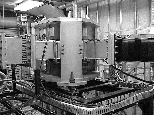
7 Klystron (Repaired Marconi) Maximum RF Power : P rf = 1.2 MW Beam Power : P b = V b *I b = 82 kv * 23.5 A = 1.93 MW Microperveance µp = I b /V b 1.5 * 10 6 = 1.00 Efficiency η = P rf /P b = 62% Gain A = 10*Log 10 (P rf /P drive ) = 45 db Drive amplifier power P drive = 40 W Cathode heater power P h = 110Vac*5.2A = 570 W Focusing magnet power P m = 70.2V*47.5A = 3.33kW No bucking coil power LCW flow for 1.5MW : 275 gpm, 150 psi, 32 ±1 o C 2 VacIon pumps, 8 L/s each
8 SPEAR 3 Klystron Spear3 klystron from Marconi That klystron was loaned to PEP2 The klystron failed, and rebuilt by PCI SLAC Klystron Dept to produce 4 klystrons Those SLAC klystrons have higher power capability Philips/EEV/Marconi Klystron Experience at SLAC No. Klystron Date failed Fil. Hrs Failure type Remedy 1 Philips #5 09/25/00 14,102 Heater short Rebuilt at CPI 2 Philips #5 03/29/01 13,895 Anode dislocation 3 Philips #5 05/22/01 5,740 Anode dislocation Rebuilt at SLAC 4 Marconi #3 07/17/01 1,350 Vacuum leak (up to 10 ma pump current) Rebuilt at CPI 5 Marconi #2 07/26/01 4,730 Vacuum leak (up to 60 ma pump current) Rebuilt at CPI

9 Marconi Klystron
10 ATF Circulator Specification Type: Y-Junction Y 3-port 3 Circulator Frequency : 476 ± 10 MHz Forward Power : 1.2 MW cw Reverse Power : 1.2 MW cw Insertion Loss : < 0.1 db (VSWR ( : <1.1, power reflection <0.25% ) Isolation : > 26 db (>14 db in ± 10 MHz) Cooling LCW : >26 gpm (150 psig, 25~40 o C, nominal 35 ± 1 o C) Mounting Orientation : any
11 AFT Circulator
12 Water Load Specification Coolant : HCW (0.75% Corr-Shield by volume to LCW) Coolant supply : 150 psig, 10~70 o C Coolant return : 15 psig, <80 o C Coolant duct : Teflon tubing Frequency : 476 ±10 MHz Power : <1.2 MW average (<2.0 MW peak for 100 µs) VSWR : <1.05 (reflected power < 0.06%) RF Leakage : < 0.1 mw/cm 2 Length : 9.5 feet overall Air pressure : <0.5 psig (0.25 psig nominal)

13 Water Load

14 HCW Station behind Booster
15 RFHV Power Supply Specification Output DC power : 90 kv* 27A=2.43 MW Corresponds to microperveance of 1.00 and 2.43 * 0.62 = 1.50 MW RF power Input AC power : kv line-to to-line, 127 A per phase Power supply efficiency = 2430/(1.73*127*12.47) = 0.89 Lower efficiency at lower output voltage/power New filtering capacitors by General Atomics Light triggered crowbar SCR s Less than 0.5 Joules to the klystron in case of arcing at 80 kv per swinging ball test of crowbar
16 RFHV Power Supply Schematic

17 Spear3 RFHV Power Supply

18 Spear3 RFHV Power Supply Grounding Tank
19 RFHV PS Swinging Ball Test
20 Spear3 RF Cavity Characteristics Frequency MHz (different from PEP MHz) Shunt Impedance R a = V 2 g /Prf rf = 7.62 MΩ M (95 kw for 0.85 MV) Acceleration field ~ 3.9 MV/m Coupling β = 1+P b /P c = 3.8 (high reflection at lower current) Window power <410 kw, Wall power < 80 W/cm 2 3 high power HOM loads at each of 4 cavities One HOM filter per cavity at the waveguide coupler Similar filters were used at Spear2 One movable tuner per cavity Coupler window temperature is monitored by IR sensor Q ~ 30,000 at operating temperature (Fill time is Q/ω ~10 µs) If RF is turned off on orbit interlock trip, beam is lost in ~300 µs

21 Spear3 RF Cavity Assembly

22 Spear3 RF Cavity Assembly

23 Cavities in the West Straight

24 Cavities in the West Straight


25 Spear3 RF System Sam Park 11/06/2003 LCW flow is 6 gallons per minute. No appreciable T is detected, but the flow is interlocked. HOM load at E- and H-mitre HOM load plate, water-cooled Cooling channels were drilled out from a solid copper plate. Matrix of 1.0 inch square ferrite tiles. They are soft- soldered onto a copper plate.

26 Spear3 RF System Sam Park Movable Tuner below the Cavity 11/06/2003
27 Movable Tuner Tuning Range y = E-06x E-04x E-02x E-01 R 2 = E-01, y = δfres, x = tuner position Resonance Shift (MHz) Tuner Position (mm)
28 Waveguide Network & Phasing Magic Tees : Divide RF power evenly. Magic tee loads are to compensate for any mismatch and absorbs reflected power (two arms are 90 degree apart) Bellow lengths are adjusted to match the RF phase in cavities Guided wavelength λ g = λ 0 /[1-(λ 0 /2a) 2 ] 1/2, λ g = c/f Waveguide sections are positively pressurized with dry air to ensure that there is no mechanical gap (no RF leakage) and no moisture enters into the system Window at the klystron is cooled by forced air

29 Magic-T T and Bellow Network

30 LLRF in Room 101, Bldg 132

31 Connections to Klystron

32 Connections to Klystron

33 Flow monitor and interlock
34 Power Balance with Beam Loading Reflect RF Power (kw) Stored Current (ma)
35
36
37
38
39 Marconi Klystron Gain Curves Vb=81kV kv kV kV 60 kv Drive Power (W) Power Out (kw)
40 Marconi Klystron Gain Curves W 400 Pdrive=60 W 40 W Klystron Beam Voltage (kv) Klystron RF Output (kw)
41
42 Booster klystron saturation 6 Figure 4 gain breakdown 5 attenuator control voltage -50X klystron drive power -20X klystron forward power 5X cavity cell power amplitude(v) time (s) Fig. 2 P(kly) vs. P(drv) at 43.5 kv P-klystrin (dbm) 55 y = x x P-drive (dbm)


43 Existing Booster RF Soft-Start, Mechanical SCR Assembly with Built-In Soft Start
44 Timing System SPEAR frequency control loop filter new components phase detect SPEAR RF VCO MHz Booster RF VCO p to SPEAR RF q bucket select phase shift h SP bucket delay MHz to Booster RF injection energy window sync sync d h B n vernier timing f Brev /n D clk D clk f SPrev ejection energy window f Brev trigger delays modulators S-band amp inject kicker chopper eject kicker SP kickers trigger delays Single-bunch filling Phase-lock Booster RF ( MHz) to SPEAR RF ( MHz) C Boo /C SPEAR = 4 / 7 f Boo /f SPEAR = 70 / 93
45 1 SPEAR BUNCH PATTERN Volts Milliseconds Driving I&Q Modulator 0.3 SPEAR BUNCH PATTERN Microseconds Test Fill Pattern in Spear2. Volts.


46 SPEAR 3 Cavity Production Cavity body milling at Accel Electroforming at Accel
 RF")
47 SPEAR 3 (PEP-II) RF Cavities


48 PEP-II RF Cavity Assemblies
Detailed Design Report
 Detailed Design Report Chapter 4 MAX IV Injector 4.6. Acceleration MAX IV Facility CHAPTER 4.6. ACCELERATION 1(10) 4.6. Acceleration 4.6. Acceleration...2 4.6.1. RF Units... 2 4.6.2. Accelerator Units...
Status of BESSY II and berlinpro. Wolfgang Anders. Helmholtz-Zentrum Berlin for Materials and Energy (HZB) 20th ESLS-RF Meeting
 20th ESLS-RF Meeting") Status of BESSY II and berlinpro Wolfgang Anders Helmholtz-Zentrum Berlin for Materials and Energy (HZB) 20th ESLS-RF Meeting 16.-17.11.2016 at PSI Outline BESSY II Problems with circulators Landau cavity
Status of BESSY II and berlinpro Wolfgang Anders Helmholtz-Zentrum Berlin for Materials and Energy (HZB) 20th ESLS-RF Meeting 16.-17.11.2016 at PSI Outline BESSY II Problems with circulators Landau cavity
INFN School on Electron Accelerators. RF Power Sources and Distribution
 INFN School on Electron Accelerators 12-14 September 2007, INFN Sezione di Pisa Lecture 7b RF Power Sources and Distribution Carlo Pagani University of Milano INFN Milano-LASA & GDE The ILC Double Tunnel
IOT OPERATIONAL EXPERIENCE ON ALICE AND EMMA AT DARESBURY LABORATORY
 IOT OPERATIONAL EXPERIENCE ON ALICE AND EMMA AT DARESBURY LABORATORY A. Wheelhouse ASTeC, STFC Daresbury Laboratory ESLS XVIII Workshop, ELLETRA 25 th 26 th November 2010 Contents Brief Description ALICE
RF Power Generation II
 RF Power Generation II Klystrons, Magnetrons and Gyrotrons Professor R.G. Carter Engineering Department, Lancaster University, U.K. and The Cockcroft Institute of Accelerator Science and Technology Scope
RF Upgrades & Experience At JLab. Rick Nelson
 RF Upgrades & Experience At JLab Rick Nelson Outline Background: CEBAF / Jefferson Lab History, upgrade requirements & decisions Progress & problems along the way Present status Future directions & concerns
3 cerl. 3-1 cerl Overview. 3-2 High-brightness DC Photocathode Gun and Gun Test Beamline
 3 cerl 3-1 cerl Overview As described before, the aim of the cerl in the R&D program includes the development of critical components for the ERL, as well as the construction of a test accelerator. The
Experience with the Cornell ERL Injector SRF Cryomodule during High Beam Current Operation
 Experience with the Cornell ERL Injector SRF Cryomodule during High Beam Current Operation Matthias Liepe Assistant Professor of Physics Cornell University Experience with the Cornell ERL Injector SRF
ANKA RF System - Upgrade Strategies
 ANKA RF System - Upgrade Strategies Vitali Judin ANKA Synchrotron Radiation Facility 2014-09 - 17 KIT University of the State Baden-Wuerttemberg and National Laboratory of the Helmholtz Association www.kit.edu
Program Risks Risk Analysis Fallback Plans for the. John T. Seeman DOE PEP-II Operations Review April 26, 2006
 Program Risks Risk Analysis Fallback Plans for the PEP-II B-FactoryB John T. Seeman DOE PEP-II Operations Review April 26, 2006 OPS Review Topics Are there any PEP-II program risks? Has the laboratory
XFEL High Power RF System Recent Developments
 XFEL High Power RF System Recent Developments for the XFEL RF Group Outline XFEL RF System Requirements Overview Basic Layout RF System Main Components Multibeam Klystrons Modulator RF Waveguide Distribution
18 GHz, 2.2 kw KLYSTRON GENERATOR GKP 24KP 18GHz WR62 3x400V
 18 GHz, 2.2 kw KLYSTRON GENERATOR GKP 24KP 18GHz WR62 3x400V With its characteristics of power stability whatever the load, very fast response time when pulsed (via external modulated signal), low ripple,
TECHNICAL SPECIFICATION Multi-beam S-band Klystron type BT267
 TECHNICAL SPECIFICATION Multi-beam S-band Klystron type BT267 The company was created for the development and manufacture of precision microwave vacuum-electron-tube devices (VETD). The main product areas
North Damping Ring RF
 North Damping Ring RF North Damping Ring RF Outline Overview High Power RF HVPS Klystron & Klystron EPICS controls Cavities & Cavity Feedback SCP diagnostics & displays FACET-specific LLRF LLRF distribution
LCLS RF Reference and Control R. Akre Last Update Sector 0 RF and Timing Systems
 LCLS RF Reference and Control R. Akre Last Update 5-19-04 Sector 0 RF and Timing Systems The reference system for the RF and timing starts at the 476MHz Master Oscillator, figure 1. Figure 1. Front end
High Brightness Injector Development and ERL Planning at Cornell. Charlie Sinclair Cornell University Laboratory for Elementary-Particle Physics
 High Brightness Injector Development and ERL Planning at Cornell Charlie Sinclair Cornell University Laboratory for Elementary-Particle Physics June 22, 2006 JLab CASA Seminar 2 Background During 2000-2001,
9th ESLS RF Meeting September ALBA RF System. F. Perez. RF System 1/20
 ALBA RF System F. Perez RF System 1/20 ALBA Synchrotron Light Source in Barcelona (Spain) 3 GeV accelerator 30 beamlines (7 on day one) 50-50 Spanish Government Catalan Government First beam for users
Operating Experience and Reliability Improvements on the 5 kw CW Klystron at Jefferson Lab
 Operating Experience and Reliability Improvements on the 5 kw CW Klystron at Jefferson Lab Richard Walker & Richard Nelson Jefferson Lab, Newport News VA Jefferson Lab is a $600M Department of Energy facility
Status and Plans for PEP-II
 Status and Plans for PEP-II John Seeman SLAC Particle and Particle-Astrophysics DOE HEPAP P5 Review April 21, 2006 Topics Luminosity records for PEP-II in October 2005 Fall shut-down upgrades Run 5b turn
14 GHz, 2.2 kw KLYSTRON GENERATOR GKP 22KP 14GHz WR62 3x400V
 14 GHz, 2.2 kw KLYSTRON GENERATOR GKP 22KP 14GHz WR62 3x400V With its characteristics of power stability independent of the load, very fast response time when pulsed (via external modulated signal), low
DELIVERY RECORD. Location: Ibaraki, Japan
 DELIVERY RECORD Client: Japan Atomic Energy Agency (JAEA) High Energy Accelerator Research Organization (KEK) Facility: J-PARC (Japan Proton Accelerator Research Complex) Location: Ibaraki, Japan 1 October
Jae-Young Choi On behalf of PLS-II Linac team
 PLS-II Linac 2015. 4. 8. Jae-Young Choi On behalf of PLS-II Linac team Accelerators in Pohang Accelerator Laboratory XFEL (under construction) 400 M$ Machines under installation PLS-II PAL : Chronology
4.4 Injector Linear Accelerator
 4.4 Injector Linear Accelerator 100 MeV S-band linear accelerator based on the components already built for the S-Band Linear Collider Test Facility at DESY [1, 2] will be used as an injector for the CANDLE
Status of SOLARIS. Paweł Borowiec On behalf of Solaris Team
 Status of SOLARIS Paweł Borowiec On behalf of Solaris Team e-mail: pawel.borowiec@uj.edu.pl XX ESLS-RF Meeting, Villingen 16-17.11.2016 Outline 1. Timeline 2. Injector 3. Storage ring 16-17.11.2016 XX
Pulsed Klystrons for Next Generation Neutron Sources Edward L. Eisen - CPI, Inc. Palo Alto, CA, USA
 Pulsed Klystrons for Next Generation Neutron Sources Edward L. Eisen - CPI, Inc. Palo Alto, CA, USA Abstract The U.S. Department of Energy (DOE) Office of Science has funded the construction of a new accelerator-based
CEBAF 8 kw CW KLYSTRON SPECIFICATION EE0043, Rev. H January 15, 1998
 Thomas Jefferson National Laboratory Specification CEBAF 8 kw CW KLYSTRON SPECIFICATION EE0043, Rev. H January 15, 1998 Approved by: Richard Nelson Date William Merz Date Claus Rode Date EE0044, Rev. H
Low Level RF for PIP-II. Jonathan Edelen LLRF 2017 Workshop (Barcelona) 16 Oct 2017
 16 Oct 2017") Low Level RF for PIP-II Jonathan Edelen LLRF 2017 Workshop (Barcelona) 16 Oct 2017 PIP-II LLRF Team Fermilab Brian Chase, Edward Cullerton, Joshua Einstein, Jeremiah Holzbauer, Dan Klepec, Yuriy Pischalnikov,
Low Level RF for PIP-II Jonathan Edelen LLRF 2017 Workshop (Barcelona) 16 Oct 2017 PIP-II LLRF Team Fermilab Brian Chase, Edward Cullerton, Joshua Einstein, Jeremiah Holzbauer, Dan Klepec, Yuriy Pischalnikov,
Diamond RF Status (RF Activities at Daresbury) Mike Dykes
 Mike Dykes") Diamond RF Status (RF Activities at Daresbury) Mike Dykes ASTeC What is it? What does it do? Diamond Status Linac Booster RF Storage Ring RF Summary Content ASTeC ASTeC was formed in 2001 as a centre of
Diamond RF Status (RF Activities at Daresbury) Mike Dykes ASTeC What is it? What does it do? Diamond Status Linac Booster RF Storage Ring RF Summary Content ASTeC ASTeC was formed in 2001 as a centre of
PEP II Design Outline
 PEP II Design Outline Balša Terzić Jefferson Lab Collider Review Retreat, February 24, 2010 Outline General Information Parameter list (and evolution), initial design, upgrades Collider Ring Layout, insertions,
Current status of XFEL/SPring-8 project and SCSS test accelerator
 Current status of XFEL/SPring-8 project and SCSS test accelerator Takahiro Inagaki for XFEL project in SPring-8 inagaki@spring8.or.jp Outline (1) Introduction (2) Key technology for compactness (3) Key
Design, Fabrication and Testing of Gun-Collector Test Module for 6 MW Peak, 24 kw Average Power, S-Band Klystron
 Available online www.ejaet.com European Journal of Advances in Engineering and Technology, 2014, 1(1): 11-15 Research Article ISSN: 2394-658X Design, Fabrication and Testing of Gun-Collector Test Module
TOSHIBA Industrial Magnetron E3328
 TOSHIBA E3328 is a fixed frequency continuous wave magnetron intended for use in the industrial microwave heating applications. The average output power is 3kW in the frequency range from 2450 to 2470
Top-Up Experience at SPEAR3
 Top-Up Experience at SPEAR3 Contents SPEAR 3 and the injector Top-up requirements Hardware systems and modifications Safety systems & injected beam tracking Interlocks & Diagnostics SPEAR3 Accelerator
RF Power Klystrons & 20 Year Look. R. Nelson 7/15/15
 RF Power Klystrons & 20 Year Look R. Nelson 7/15/15 RF Power klystrons 8 x 13 kw klystrons Page 2 Why A klystron? Best (only) choice at the time - 1988 Easy to use: Input (drive), output (to CM), power
LLRF at SSRF. Yubin Zhao
 LLRF at SSRF Yubin Zhao 2017.10.16 contents SSRF RF operation status Proton therapy LLRF Third harmonic cavity LLRF Three LINAC LLRF Hard X FEL LLRF (future project ) Trip statistics of RF system Trip
!"!3
 Abstract A single-mode 500 MHz superconducting cavity cryomodule has been developed at Cornell for the electronpositron collider/synchrotron light source CESR. The Cornell B-cell cavity belongs to the
The ALS RF systems, upgrades and ALS-U plans
 The ALS RF systems, upgrades and ALS-U plans M. Betz*, K. Baptiste, Q. Du, M. Vinco, S. Virostek 06/27/2018, CWRF2018, Hsinchu, Taiwan * mbetz@lbl.gov Outline Structure of this talk RF systems in the Advanced
Next Linear Collider. The 8-Pack Project. 8-Pack Project. Four 50 MW XL4 X-band klystrons installed on the 8-Pack
 The Four 50 MW XL4 X-band klystrons installed on the 8-Pack The Demonstrate an NLC power source Two Phases: 8-Pack Phase-1 (current): Multi-moded SLED II power compression Produce NLC baseline power: 475
Synchrotron Light Facility. Operation of ALBA RF. Angela Salom on behalf of RF team: Francis Perez, Bea Bravo and Jesus Ocampo
 Operation of ALBA RF Angela Salom on behalf of RF team: Francis Perez, Bea Bravo and Jesus Ocampo Outline ALBA RF Overview: Booster and SR RF Operation with beam Statistics of first year operation Cavities
Status of RF Power and Acceleration of the MAX IV - LINAC
 Status of RF Power and Acceleration of the MAX IV - LINAC Dionis Kumbaro ESLS RF Workshop 2015 MAX IV Laboratory A National Laboratory for synchrotron radiation at Lunds University 1981 MAX-lab is formed
STATUS OF THE SWISSFEL C-BAND LINEAR ACCELERATOR
 Proceedings of FEL213, New York, NY, USA STATUS OF THE SWISSFEL C-BAND LINEAR ACCELERATOR F. Loehl, J. Alex, H. Blumer, M. Bopp, H. Braun, A. Citterio, U. Ellenberger, H. Fitze, H. Joehri, T. Kleeb, L.
RF plans for ESS. Morten Jensen. ESLS-RF 2013 Berlin
 RF plans for ESS Morten Jensen ESLS-RF 2013 Berlin Overview The European Spallation Source (ESS) will house the most powerful proton linac ever built. The average beam power will be 5 MW which is five
RF Power Upgrade at Jefferson Lab
 RF Power Upgrade at Jefferson Lab Rick Nelson*, Andrew Kimber *nelson@jlab.org * Notice: Authored by Jefferson Science Associates, LLC under U.S. DOE Contract No. DE- AC05-06OR23177. The U.S. Government
The Elettra Storage Ring and Top-Up Operation
 The Elettra Storage Ring and Top-Up Operation Emanuel Karantzoulis Past and Present Configurations 1994-2007 From 2008 5000 hours /year to the users 2010: Operations transition year Decay mode, 2 GeV (340mA)
A Unique Power Supply for the PEP II Klystron at SLAC*
 I : SLAC-PUB-7591 July 1997 A Unique Power Supply for the PEP II Klystron at SLAC* R. Case1 and M. N. Nguyen Stanford Linear Accelerator Center Stanford University, Stanford, CA 94309 Presented at the
KARA and FLUTE RF Overview/status
 KARA and FLUTE RF Overview/status Nigel Smale on behalf of IBPT and LAS teams Laboratory for Applications of Synchrotron radiation (LAS) Institute for Beam Physics and Technology (IBPT) KARA KIT The Research
RF Solutions for Science.
 RF Solutions for Science www.thalesgroup.com State-of-the-art RF sources for your scientific needs High-power klystrons HIGH KLYSTRONS WITH RF LONG PULSE above 50 μs Thales has been one of the leading
Introduction: CW SRF linac types, requirements and challenges High power RF system architecture
 RF systems for CW SRF linacs S. Belomestnykh Cornell University Laboratory for Elementary-Particle Physics LINAC08, Victoria, Canada October 1, 2008 Outline L band Introduction: CW SRF linac types, requirements
KEKB INJECTOR LINAC AND UPGRADE FOR SUPERKEKB
 KEKB INJECTOR LINAC AND UPGRADE FOR SUPERKEKB S. Michizono for the KEK electron/positron Injector Linac and the Linac Commissioning Group KEK KEKB injector linac Brief history of the KEK electron linac
The LEP Superconducting RF System
 The LEP Superconducting RF System K. Hübner* for the LEP RF Group CERN The basic components and the layout of the LEP rf system for the year 2000 are presented. The superconducting system consisted of
IOT RF Power Sources for Pulsed and CW Linacs
 LINAC 2004 Lübeck, August 16 20, 2004 IOT RF Power Sources H. Bohlen, Y. Li, Bob Tornoe Communications & Power Industries Eimac Division, San Carlos, CA, USA Linac RF source property requirements (not
A New 4MW LHCD System for EAST
 1 EXW/P7-29 A New 4MW LHCD System for EAST Jiafang SHAN 1), Yong YANG 1), Fukun LIU 1), Lianmin ZHAO 1) and LHCD Team 1) 1) Institute of Plasma Physics, Chinese Academy of Sciences, Hefei, China E-mail
SRS and ERLP developments. Andrew moss
 SRS and ERLP developments Andrew moss Contents SRS Status Latest news Major faults Status Energy Recovery Linac Prototype Latest news Status of the RF system Status of the cryogenic system SRS Status Machine
A HIGH POWER LONG PULSE HIGH EFFICIENCY MULTI BEAM KLYSTRON
 A HIGH POWER LONG PULSE HIGH EFFICIENCY MULTI BEAM KLYSTRON A.Beunas and G. Faillon Thales Electron Devices, Vélizy, France S. Choroba DESY, Hamburg, Germany Abstract THALES ELECTRON DEVICES has developed
GA A26497 SOLID-STATE HIGH-VOLTAGE CROWBAR UTILIZING SERIES-CONNECTED THYRISTORS
 GA A26497 SOLID-STATE HIGH-VOLTAGE CROWBAR by J.F. Tooker, P. Huynh, and R.W. Street JUNE 2009 DISCLAIMER This report was prepared as an account of work sponsored by an agency of the United States Government.
ILC-LNF TECHNICAL NOTE
 IL-LNF EHNIAL NOE Divisione Acceleratori Frascati, July 4, 2006 Note: IL-LNF-001 RF SYSEM FOR HE IL DAMPING RINGS R. Boni, INFN-LNF, Frascati, Italy G. avallari, ERN, Geneva, Switzerland Introduction For
KLYSTRON GUN ARCING AND MODULATOR PROTECTION
 SLAC-PUB-10435 KLYSTRON GUN ARCING AND MODULATOR PROTECTION S.L. Gold Stanford Linear Accelerator Center (SLAC), Menlo Park, CA USA Abstract The demand for 500 kv and 265 amperes peak to power an X-Band
L-Band RF R&D. SLAC DOE Review June 15 th, Chris Adolphsen SLAC
 L-Band RF R&D SLAC DOE Review June 15 th, 2005 Chris Adolphsen SLAC International Linear Collider (ILC) RF Unit (TESLA TDR Layout) Gradient = 23.4 MV/m Bunch Spacing = 337 ns Fill Time = 420 µs Train Length
News from HZB / BESSY Wolfgang Anders at ESLS-RF Meeting September 2010 Trieste
 News from HZB / BESSY Wolfgang Anders at ESLS-RF Meeting September 2010 Trieste Outline Status Klystrons / IOT Modifications of transmitters New LINAC for BESSY II Status BERLinPro HoBiCaT Extension --
SLS RF operation report 2003
 SLS RF operation report 2003 M. Pedrozzi, Jean-Yves Raguin Paul Scherrer Institute, 5232 Villigen PSI, Switzerland SUMMARY LINAC report SR Superconducting Third Harmonic system report SR 500 MHz system
Karin Rathsman. Calculations on the RF Source and Distribution
 Accelerator Division ESS AD Technical Note ESS/AD/0002 Karin Rathsman Calculations on the RF Source and Distribution 26 March 2010 Calculations on the rf source and distribution system for the ESS elliptical
The PEFP 20-MeV Proton Linear Accelerator
 Journal of the Korean Physical Society, Vol. 52, No. 3, March 2008, pp. 721726 Review Articles The PEFP 20-MeV Proton Linear Accelerator Y. S. Cho, H. J. Kwon, J. H. Jang, H. S. Kim, K. T. Seol, D. I.
SPEAR 3: Operations Update and Impact of Top-Off Injection
 SPEAR 3: Operations Update and Impact of Top-Off Injection R. Hettel for the SSRL ASD 2005 SSRL Users Meeting October 18, 2005 SPEAR 3 Operations Update and Development Plans Highlights of 2005 SPEAR 3
RF POWER GENERATION FOR FUTURE LINEAR COLLIDERS* 1. Introduction
 SLAC-PUB-5282 June 1990 (A) RF POWER GENERATION FOR FUTURE LINEAR COLLIDERS* W. R. Fowkes, M. A. Allen, R. S. Callin, G. Caryotakis, K. R. Eppley, K. S. Fant, Z. D. Farkas, J. Feinstein, K. Ko, R. F. Koontz,
PEP-II Overview & Ramp Down Plan. J. Seeman DOE PEP-II Ramp Down-D&D Review August 6-7, 2007
 PEP-II Overview & Ramp Down Plan J. Seeman DOE PEP-II Ramp Down-D&D Review August 6-7, 2007 Topics Overview of the PEP-II Collider PEP-II turns off September 30, 2008. General list of components and buildings
Upgrading LHC Luminosity
 1 Upgrading LHC Luminosity 2 Luminosity (cm -2 s -1 ) Present (2011) ~2 x10 33 Beam intensity @ injection (*) Nominal (2015?) 1 x 10 34 1.1 x10 11 Upgraded (2021?) ~5 x10 34 ~2.4 x10 11 (*) protons per
Design Studies For The LCLS 120 Hz RF Gun Injector
 BNL-67922 Informal Report LCLS-TN-01-3 Design Studies For The LCLS 120 Hz RF Gun Injector X.J. Wang, M. Babzien, I. Ben-Zvi, X.Y. Chang, S. Pjerov, and M. Woodle National Synchrotron Light Source Brookhaven
RF considerations for SwissFEL
 RF considerations for H. Fitze in behalf of the PSI RF group Workshop on Compact X-Ray Free Electron Lasers 19.-21. July 2010, Shanghai Agenda Introduction RF-Gun Development C-band development Summary
PEP-I1 RF Feedback System Simulation
 SLAC-PUB-10378 PEP-I1 RF Feedback System Simulation Richard Tighe SLAC A model containing the fundamental impedance of the PEP- = I1 cavity along with the longitudinal beam dynamics and feedback system
PEP II STATUS AND PLANS *
 PEP II STATUS AND PLANS * John T. Seeman + Stanford Linear Accelerator Center, Stanford University, Stanford, CA 94309 USA The PEP II B-Factory 1 project is an e + e - colliding beam storage ring complex
ABORT DIAGNOSTICS AND ANALYSIS DURING KEKB OPERATION
 ABORT DIAGNOSTICS AND ANALYSIS DURING KEKB OPERATION H. Ikeda*, J. W. Flanagan, T. Furuya, M. Tobiyama, KEK, Tsukuba, Japan M. Tanaka, MELCO SC,Tsukuba, Japan Abstract KEKB has stopped since June 2010
AARHUS UNIVERSITET November, ASTRID2 Status. Heine Dølrath Thomsen on behalf of the ASTRID2 Team
 21-22 November, 2013 ASTRID2 Status Heine Dølrath Thomsen on behalf of the ASTRID2 Team præsen TATION ASTRID2 ASTRID2 is the new synchrotron light source being commissioned in Aarhus, Denmark ASTRID2 main
Status of SOLARIS Arkadiusz Kisiel
 Status of SOLARIS Arkadiusz Kisiel Solaris National Synchrotron Light Source Jagiellonian University Czerwone Maki 98 30-392 Kraków www.synchrotron.uj.edu.pl Arkadiusz.Kisiel@uj.edu.pl On behalf of SOLARIS
OF THIS DOCUMENT IS W8.MTO ^ SF6
 fflgh PEAK POWER TEST OF S-BAND WAVEGUIDE SWITCHES A. Nassiri, A. Grelick, R. L. Kustom, and M. White CO/0 ^"^J} 5, t * y ^ * Advanced Photon Source, Argonne National Laboratory» \^SJ ^ ^ * **" 9700 South
Evaluation of Performance, Reliability, and Risk for High Peak Power RF Sources from S-band through X-band for Advanced Accelerator Applications
 Evaluation of Performance, Reliability, and Risk for High Peak Power RF Sources from S-band through X-band for Advanced Accelerator Applications Michael V. Fazio C. Adolphsen, A. Jensen, C. Pearson, D.
Review of Diamond SR RF Operation and Upgrades
 Review of Diamond SR RF Operation and Upgrades Morten Jensen on behalf of Diamond Storage Ring RF Group Agenda Stats X-ray and LN2 pressure results Cavity Failure Conditioning in the RFTF Cavity Simulations
Improvements to the APS LINAC and SR/Booster klystron HVPS, and Accomplishments of the 352MHz RFTS
 Improvements to the APS LINAC and SR/Booster klystron HVPS, and Accomplishments of the 352MHz RFTS G. Trento Accelerator Systems Division Argonne National Laboratory Work supported by the U.S. Department
Status of Elettra, top-up and other upgrades
 Status of Elettra, top-up and other upgrades Emanuel Karantzoulis ELETTRA / Trieste, Italy / 2010 November 25-26 Past and Present Configurations 1994-2007 From 2008 No full energy injection Full energy
THE NEXT LINEAR COLLIDER TEST ACCELERATOR: STATUS AND RESULTS * Abstract
 SLAC PUB 7246 June 996 THE NEXT LINEAR COLLIDER TEST ACCELERATOR: STATUS AND RESULTS * Ronald D. Ruth, SLAC, Stanford, CA, USA Abstract At SLAC, we are pursuing the design of a Next Linear Collider (NLC)
45 MW, 22.8 GHz Second-Harmonic Multiplier for High-Gradient Tests*
 US High Gradient Research Collaboration Workshop. SLAC, May 23-25, 2007 45 MW, 22.8 GHz Second-Harmonic Multiplier for High-Gradient Tests* V.P. Yakovlev 1, S.Yu. Kazakov 1,2, and J.L. Hirshfield 1,3 1
reported by T. Shintake KEK / RIKEN Japan Summary of C-band R&D for Linear Collider at KEK New soft-x-ray FEL Project at RIKEN/SPring-8
 C-band RF System R&D reported by T. Shintake KEK / RIKEN Japan Summary of C-band R&D for Linear Collider at KEK New soft-x-ray FEL Project at RIKEN/SPring-8 Project was funded in 2001 April Material Science
Karin Rathsman, Håkan Danared and Rihua Zeng. Report from RF Power Source Workshop
 Accelerator Division ESS AD Technical Note ESS/AD/0020 Karin Rathsman, Håkan Danared and Rihua Zeng Report from RF Power Source Workshop 10 July 2011 Report on the RF Power Source Workshop K. Rathsman,
PEP-II STATUS REPORT *
 PEP-II STATUS REPORT * Jonathan Dorfan Stanford Linear Accelerator Center, Stanford University, Stanford, CA 94309 USA For the SLAC, LBNL, LLNL PEP-II group Abstract The main design features of the PEP-II
Status of CTF3. G.Geschonke CERN, AB
 Status of CTF3 G.Geschonke CERN, AB CTF3 layout CTF3 - Test of Drive Beam Generation, Acceleration & RF Multiplication by a factor 10 Drive Beam Injector ~ 50 m 3.5 A - 2100 b of 2.33 nc 150 MeV - 1.4
EPJ Web of Conferences 95,
 EPJ Web of Conferences 95, 04012 (2015) DOI: 10.1051/ epjconf/ 20159504012 C Owned by the authors, published by EDP Sciences, 2015 The ELENA (Extra Low Energy Antiproton) project is a small size (30.4
650MHz/800kW Klystron Development at IHEP
 650MHz/800kW Klystron Development at IHEP Shilun Pei, IHEP On behalf of HERSC (High Efficiency RF Source R&D Collaboration) in China Presentation at the IAS Program on High Energy Physics January 22, 2018,
Tutorial: Trak design of an electron injector for a coupled-cavity linear accelerator
 Tutorial: Trak design of an electron injector for a coupled-cavity linear accelerator Stanley Humphries, Copyright 2012 Field Precision PO Box 13595, Albuquerque, NM 87192 U.S.A. Telephone: +1-505-220-3975
PULSED MODULATOR TECHNOLOGY
 PULSED MODULATOR TECHNOLOGY Hiroshi MATSUMOTO J-PARC/KEK CONTENTS 1. VARIOUS REQUIREMENT OF THE RECENT MODULATORS SHORT PULSE WIDTH (~µsec) LONG PULSE WIDTH (~msec) AND HIGH REP. RATE. (200 Hz) OUTPUT
Linac upgrade plan using a C-band system for SuperKEKB
 Linac upgrade plan using a C-band system for SuperKEKB S. Fukuda, M. Akemono, M. Ikeda, T. Oogoe, T. Ohsawa, Y. Ogawa, K. Kakihara, H. Katagiri, T. Kamitani, M. Sato, T. Shidara, A. Shirakawa, T. Sugimura,
PRESENT STATUS OF J-PARC
 PRESENT STATUS OF J-PARC # F. Naito, KEK, Tsukuba, Japan Abstract Japan Proton Accelerator Research Complex (J-PARC) is the scientific facility with the high-intensity proton accelerator aiming to realize
PEP II Status and Plans
 SLAC-PUB-6854 September 1998 PEP II Status and Plans By John T. Seeman Invited talk presented at the 16th IEEE Particle Accelerator Conference (PAC 95) and International Conference on High Energy Accelerators,
The basic parameters of the pre-injector are listed in the Table below. 100 MeV
 3.3 The Pre-injector The high design brightness of the SLS requires very high phase space density of the stored electrons, leading to a comparatively short lifetime of the beam in the storage ring. This,
The TESLA RF System. S. Choroba. for the TESLA Collaboration. DESY Notkestr. 85, D Hamburg, Germany
 The TESLA RF System S. Choroba for the TESLA Collaboration DESY Notkestr. 85, D-22603 Hamburg, Germany Abstract. The TESLA project proposed by the TESLA collaboration in 2001 is a 500 to 800GeV e+/e- linear
CEPC Klystron Development
 CEPC Klystron Development Zusheng Zhou On behalf of High Efficiency RF Source R&D Collaboration Institute of High Energy Physics Sep. 26, 2018, HKUST, Hong Kong 1 Outline Strategy and plan 650MHz/800kW
4617 Super Power Triode
 4617 Super Power Triode Matrix-Oxide-Type Cathode DoubIe-Ended Terminal Configuration for Symmetrical Circuity Liquid Cooled Peak Power Output - 8 MW The BURLE-4617 is a water-cooled super-power triode
FIR Center Report. Development of Feedback Control Scheme for the Stabilization of Gyrotron Output Power
 FIR Center Report FIR FU-120 November 2012 Development of Feedback Control Scheme for the Stabilization of Gyrotron Output Power Oleksiy Kuleshov, Nitin Kumar and Toshitaka Idehara Research Center for
Pulses inside the pulse mode of operation at RF Gun
 Pulses inside the pulse mode of operation at RF Gun V. Vogel, V. Ayvazyan, K. Floettmann, D. Lipka, P. Morozov, H. Schlarb, S. Schreiber FLASH Seminar, DESY March 29, 2011 Contents Why we need a PiPmode
CLIC Feasibility Demonstration at CTF3
 CLIC Feasibility Demonstration at CTF3 Roger Ruber Uppsala University, Sweden, for the CLIC/CTF3 Collaboration http://cern.ch/clic-study LINAC 10 MO303 13 Sep 2010 The Key to CLIC Efficiency NC Linac for
Klystron Lifetime Management System
 Klystron Lifetime Management System Łukasz Butkowski Vladimir Vogel FLASH Seminar Outline 2 Introduction to KLM Protection and measurement functions Installation at Klystron test stand FPGA implementation
A HIGH-POWER SUPERCONDUCTING H - LINAC (SPL) AT CERN
 AT CERN") A HIGH-POWER SUPERCONDUCTING H - LINAC (SPL) AT CERN E. Chiaveri, CERN, Geneva, Switzerland Abstract The conceptual design of a superconducting H - linear accelerator at CERN for a beam energy of 2.2 GeV
A HIGH-POWER SUPERCONDUCTING H - LINAC (SPL) AT CERN E. Chiaveri, CERN, Geneva, Switzerland Abstract The conceptual design of a superconducting H - linear accelerator at CERN for a beam energy of 2.2 GeV