IMCFW-350 FLOW WRAPPER MACHINE
|
|
|
- Luke Thomas
- 5 years ago
- Views:
Transcription

1 IMCFW-350 FLOW WRAPPER MACHINE INTERNATIONAL MACHINE CONCEPTS WELCOMES YOU TO YOUR NEW MACHINE Operation Manual: Date 2018
2 CONTENTS Chapter 1 Machine Description 1.1 Uncrating Instructions 1.2 Installation 1.3 Installation of machine parts and components Electrical connections 1.4 Chapter 2 Technical Parameters and Description 2.1 Chapter 3 Operating Instruction Starting the machine for the first time 3.0 Packaging material loading 3.1 Computer screens and description 3.2 Mechanical description and adjustments 3.3 In-feed Product Chain Adjustment Film Guide and Packaging film Fitting Bag Former adjustment Longitudinal roller and adjustment Horizontal sealing rollers and adjustment Cutter blade adjustment Heater slip rings and adjustment 3.3.7
3 Chapter 4 Malfunctions (Faults) and their rectification Table of possible faults 4.1 Chapter 5 Maintenance instructions 5.1 Chapter 6 Mechanical Drawing 6.1 Electrical Panel Layout 6.2 Sensors Location Drawing 6.3 Chapter 7 Electrical diagrams 7.1 Chapter 8 Manufacturers manuals 8.1 Servo drivers Temperature controllers Chapter 9 Spare parts list 9.1
4 Chapter Machine Description This machine is the latest in our series of flow wrappers, the machine has many advanced functions that will be explained later in the manual. The main function of this flow wrapper is to perform a packet sealed around the product. The film is formed via a forming shoulder and then sealed as a center seal under the product and then transferred to the back and front sealer thereby forming a complete packet around the product. The machine is fully automated and consist of various control mechanisms to perform the full function. The main systems are. In-feed product transfer belt Film holder and guide system Film forming shoulder Longitudinal sealing system Front and back sealing system with cut off knife. The film registration is a sub system of the film guide system, The entire machine is servo system driven and is electronically clutched together via a PLC and Touch screen. All the systems on the machine can be controlled via the Touch Screen including individually for checking purposes. v Correct setting up of the machine is essential for correct operation and specific attention should be paid to the following areas. The person who operates this packaging machine must know the contents of this manual in detail. The operator and at least two mechanical and electrical staff will need to be trained on the machine after commissioning to ensure that daily maintenance of the machine. NOTE: All these areas will be covered in a later chapter (Chapter 3) Machine Safety Guides The following safety guides pertaining to this machine must be observed in order to prevent accidents with this machine: The installation of all safety devices, such as protective doors, must be closed to enable the machine to operate. Note these parts cannot be dismantled. The machine operators must check the machine for any foreign objects that could cause damage to the machine prior to switching on and operation. Once the machine is running, no hands are to be placed or inserted near the
5 sealing area as well as any of the running parts Safety with the Operational Parts The air source and power supply must be switched off when the machine is being cleaned or repaired. If the machine is equipped with a hopper, do not insert hands or fingers into the filling device during operation. Please report any damaged safety equipment on the machine as soon as damage is noted. The entire power and air supply source must be cut off during non production. v Please note: Mechanical and bodily harm will be caused if the following parts are tampered with during production: The heating block at the sealing device. The sealing and opening area of the heat-sealing device. The moving parts at the bag-feeding device. The area at the cam transmission mechanism. (Rear of machine) In case of emergency, press the red EMERGENCY STOP button on the machine. The machine will stop running immediately. After troubleshooting, the button can be reset The Safety Devices Clear Safety Protection Cover The Safety Protective door is made of transparent plexi glass and needs to be closed in order to avoid contact with moving parts on the machine when in production. The machine can only be run for a short time with the safety doors open and only by the remote run jog button Emergency Shutdown Button In case of emergency, press the red EMERGENCY STOP button on the machine. The machine will stop running immediately. After troubleshooting, the button can be reset. Reset the Emergency Shutdown Button after activation by releasing with a quarter turn Safety Covers Check The state of the safety protection cover must be inspected before restarting the machine.
6 1.1.4 Structural Principles Structural Composition This machine is made up the following parts the electronic control system, the pneumatic control system, the bag installation system, bag pickup system, opening of the bag system, moving of the bag system, filling of the bag system, the upper seal system, the mechanical transmission system. Electrical Composition The electrical part of the machine consists of a PLC programmed by a computer programmer; a frequency converter runs this system. this is a highly integrated, well-controlled and reliable operation. The application of the touch screen technology allows for a more reliable, convenient and interactive interfacing for the operator. The Photo-electric Sensors, Encoders, proximity switches and various other switches are made up of high quality advanced sensor components, this allows for precise performance of the mechanical and electrical components A brief Introduction to the Packing Principle Packaging Process The product is transported to the bag forming section via a finger transport chain. The film is guided through a film guide section to the forming shoulder. The film and product meet at this section, The film is then formed around the product and a center bottom fin seal is created. The film is pulled through by bottom heated rollers both pulling and sealing the film. The formed pouch is now passed through the horizontal sealing and cutting station to cut the pouches into individual sections or packets. Multiple packets are also possible via settings on the touch screen. v This machine cannot use materials that are not composite. The recommended film is PET/PE. However various types of films can be accommodated as long as the outside film melts at a lower temperature than the inner film. PET/plated AL/PE, PET/PE, PAPER/PE, NYLON, etc.
7 Main Machine Components Structural Features Double-servo and single frequency conversion control this means that the bag length can be set and cut in one step. An automatic stop will occur when a bag is not filled in the production line the film cutter and film feed action will be halted. The temperature control module is independent of the PID control which allows for accuracy and is suitable for different packaging materials to be used. Touch screen allows for ease of use with operation and settings. All machine control are carried out on the PLC for ease of use. Emergency stop button will halt the machine instantly this will stop blades from sticking as well as prevent film wastage. PAPER FEEDING MECHANISM CONTROL SYSTEM BELT-TYPE DISCHARGE MECHANISM FEEDING MECHANISM BAG MAKER END-SEALING MECHANISM FRAME MID-SEALING MECHANISM DRIVING MECHANISM! 1.2 Un-crating Instructions The machine is generally transported in wooden crates. During uncrating make sure that no physical damage to the outside of the crate has taken place. Carefully break open the exterior panels to reveal the machine and its working parts. The machine will be covered in a plastic protective cover. This is to be removed. Make sure that no parts have been damaged during transport, or fallen off the machine. The machine will get to you with certain parts dis-assembled. These need to be fitted to the machine to resemble the photos above of the machine. The machine is affixed to the wooden pallet by four metal brackets. Remove these brackets and discard or keep for future use. The doors and
8 covers have been taped closed for safety reasons; these taped parts can now be opened. Surface rust can take place due to the excessive sea air during shipping. This will only be surface rust and a dry cloth should be used to remove this rust residue. The entire machine was shipped with an oil coating on the machine to safeguard the machine from corrosion. This can now be removed with a very light detergent. The non stainless steel parts should be re-oiled to prevent rusting taking place after cleaning. Do not leave the machine wet. The machine is top heavy and as such care should be taken when handling the machine and removing it from its wooden pallet. Handling After unpacking, a forklift can be used to maneuver the machine into position; the length of the fork must be long enough to reach under the width of the machine. See figure below. The center of gravity of the machine is about 1500mm from the right hand side (the electrical box side) frontal view of machine. NOTE: Do not handle the machine on the upper surface of the machine. This area has safety covers that might break. Under these covers are the upper movement systems. These parts are critically aligned and should they be bent out of position the bags may run off and the machine will not function. 1.3 Installation v Only a qualified technician should perform the machine installation or a suitably trained person. Note: It is dangerous to work on a moving machine and the machine should be off and isolated before any form of work is performed Machine should be placed in a well- ventilated room free from dust and excessive corrosion type materials


9 There should be at least 1.5 meters space around each side of the machine for convenient operation and maintenance. Power Requirements; three Phase, 220V, 50Hz, three-wire power supply, and to connect to an appropriate earth wire Steps of installation of the machine parts 1. The first step is to determine the installation position, refer to diagram 3. After the machine is set, take the worktable as the level reference to adjust the four level adjusting screws, set the main machine in a level position. 2. Install the feeding machine, fix it to the left side of the main machine with bolts, then adjust the two level adjusting screws of the feeding machine, set it in a level position. For the part connecting with the main machine, the bottom of the feeding chute and the main machine table should be aligned and kept in a same level. 3. Install the push finger chain. Loosen the left hand-wheel (see diagram 2) of the feeding machine, and install and connect the push finger chain. Turn the hand-wheel to adjust the push finger chain to a proper tension. 4. Connect power supply line. This machine uses single-phase 220V, 50HZ power supply. Never connect to 380V or other unqualified power supply. Special attention must be paid to this requirement! In order to ensure safety, all wiring work should be carried out by qualified professional electricians. Fit the end conveyor to the out-feed of the machine the out-feed conveyor must be joined to the drive by the supplied chain, ensure that the chain is tight by adjusting the jockey tensioner


10 Fit the in-feed conveyor to the main body with the bolts as shown. Firstly connect the legs to the conveyor with bolts shown. Ensure that the in-feed conveyor is straight and level with the machine body. The in-feed conveyor chain can now be fitted to the in-feed conveyor frame ensuring that the chain is tensioned around the in-feed conveyor drive sprockets and rear idler sprockets. The chain can be tensioned using the two tensioning levers at the rear of the in-feed conveyor NOTES: Check every part of the machine carefully for damage during shipping. Tighten any loose parts, screws and moving parts. All gearboxes should be checked for sufficient oil Check all electrical connections for loose wires. Make a test of the machines electrical power supply and confirm the voltage and earth continuity. All safety connections relative to your own country should be adhered too. TEST Voltage: Phase to Neutral 220v AC Phase to Earth - >5000m Ohms Earth continuity <1 Ohm Before operating the machine, please lubricate the following parts: linear bearings and its bearing holes located in the rack system (Cover), cams located on horizontal main shaft. Although the machine has been designed to be virtually oil free. No two metal parts can run without some type of

11 lubrication. The upper moving parts should be lubricated with silicon spray periodically to reduce wear Operation Panel Introduction Introduction to the Switch on the Operation Control Box Control Panel Start -- The machine will start to run. Control Panel Stop -- The machine will be stopped in position. Control Panel Inching The machine will inch forward. Control Panel -- Print Mark Light On Button. Control Panel Emergency Stop Emergency stop of the entire machine. Control Panel power On Light. Control Panel Mid Heater -- Heating on/off Switch Control Panel End Heater -- Heating on/off Switch Control Panel Temperature Controller -- Mid Sealing elements/longitudinal Sealing elements Control Panel Temperature Controller -- End Sealing elements/horizontal Sealing elements To Stop the machine: Use the Control Panel Stop Button. v Emergency Stop Button This will stop the machine from running immediately, this stop should only be used in an emergency condition.


12 1.3.3 The Motor Make sure the rotation of the motor-driven cam is correct: Description of the machine This machine is designed for packing fixed shaped materials into pillow packets, for example: biscuits, candies and nuts. 1.4 Electrical connection Main Power supply connection 220v AC 2 wire plus earth
13 Chapter Machine Specification, Parameters and Description Model Cutter type Film Width Bag length Product Width Product Height Film Roll Diameter Packaging Rate Power Machine Size (L x W x H) Machine Weight HDL-350DS Rotary Max: 350mm mm mm Max 40mm Max:320mm Bags/min 220V, 50/60Hz, 2,4KW 3812x875x kg * The actual working environment shall be based on the characteristics of the packaging materials. Speeds can be compromised by material and powder characteristics.
14 Chapter 3 Operating Instructions 3.0 Starting the machine for the first time Make sure that the power supply has been connected correctly. Connect all circuit breakers in the control cabinet, check meters and power indicator lamps on the control panel are normal. Test the Jog button. Set packing speed at 40 bags per minute, press start button and run the machine for 3 to 5 minutes making sure that the machine is running properly. Press the Stop button. It is always advisable to rotate the machine at very slow speed using the jog function to ensure that the parts as shown above operate correctly. Testing using the manual functions can be performed before automatic function is processed. Ensure that all the above installation is carried out and tested before starting the machine for the first time. Full knowledge of the touch screen system should be understood before starting the machine. v No mechanical obstruction should be noted and all lubrication should be carried out. v Electrical tests to determine correct voltage and phasing (direction) must be carried out v Pneumatic connection must be made and pressure should be correct. Proceed with caution: Mechanical description and adjustments Feeding Mechanism The feeding mechanism of the machine is equipped with two Push-finger Chain tension adjusting Hand Wheels on the left hand side of the feeding mechanism. Once the product type is established, the width of the guide chute of the feeding mechanism can be adjusted to accommodate the product to be packed. Packaging material-feeding mechanism Once the packing film roll has been installed on the automatic central aligning clamping roller, the film must be fed through the machine depending on whether the machine has a code-printer installed or not. See diagrams below in packaging Material Loading.
15 Diagrammatic film route when the machine is equipped with a code-printing machine Diagrammatic film route when the machine is not equipped with a codeprinting machine
16 Regardless of whether the machine is equipped with a code printer or not, when the film enters the bag maker, open the mid-sealing open and close handle, pass the film through the film pull wheel, midsealing heating board, press-fit wheel. Once this is done, close the open-and-close handle. Jog the machine, making the film pass through the end-sealing knife. The film is now properly installed. Packing film tensioning and alignment adjustment When the film passes through the bag-making mechanism and is uneven, adjust the Swing Roll or the angle of the Swing Link ( see Diagram ) this will alter the position between the Swing Roll and Bag Maker. If the Mid-sealing of the packed product is uneven, adjust the Packing Film Central Aligning Adjusting Hand wheel. (see diagram ) Adjust until the two sides of the mid-sealing are aligned. The width and film elevation on the Bag Former is adjustable. The width can be adjusted with the Bag-Maker Hand wheel. Add 5mm to the actual width of the packaging material. To adjust the height of the bag, loosen the fixing Hand wheel, moving the bag up or down to adjust the height. Again add 5mm to the actual bag size that the machine is rewired to make. Tighten the Hand wheel once all adjustments have been made. The Mid-Sealing Mechanism consists of a paper-pull wheel, heating block, press-fit wheel and open-and-close hand wheel. If the the packing film is too tight or loose as it passes through the Paper-Pull Wheel, heating block or the press-fit wheel it needs to be adjusted with the Press-Fit Wheel Speed adjusting Hand wheel. Mid sealing should result in a tight sealing and clear lines, if not, the following steps should be followed: Place two white papers with a carbon paper between into the missealing wheel and turn one revolution, remove the papers, the printed markings should be clear, if not, adjust the meshing position between the two wheels. Check the printed markings again. Repeat the above process until the lines are clear on the papers. If the meshing is correct as well as the temperature, but the sealing quality is still poor, the Set Screws need to be adjusted to increase or decrease the meshing pressure of the sealing wheel. The mid-sealing parts have been factory set, so there should be no need to adjust the Mid-sealing Mechanism. End Sealing Mechanism consists of an End sealing knife. This should not need further adjustments, but if needed, the following steps need to be followed: Again use two white papers with a carbon paper between, test whether the marks on the paper are even and clear. Loosen the M10 Screw slightly, adjust the Cross Adjusting Screw to the correct position on the Cutter Seat. Tighten the M10 Screw.
17 Adjusting the height of the End-Sealing knife Holder This should be adjusted according to the height of the packed product so as to make the meshing center of the sealing knife align with the height of the packed product. To adjust, loosen the screws of the side board of the cutter holder, then adjust the upward and downward adjusting screw of the endsealing (middle screw), making the distance between the meshing position of the upper and lower sealing knives and working plane about half the height of the packed product. After adjusting tighten the four screws. Temperature Control This machine has two sets of temperature control systems, which control the longitudinal-sealing Temperature and the Horizontal- Sealing Temperature. The temperature value for each set of temperature control systems is determined by the packing speed, the thickness of the packing film being used and the outside temperature. The optimal temperature setting value should produce a result that has no leaking or burnt crimpled seals on the bags for both mid and end seals. Color-mark Eye Once packing film has been installed, adjust the position of the electric eye, along the beam emitted from the eye to the colour-mark on the film. See diagram below:
18 3.1 Computer screens and description Operation Screen In this screen you can set the basic parameters according to required specification. Length of bag Push the length of bag button to reveal the digital input keypad, enter bag length in millimeters. If the bag length setting is set beyond the max length, the screen will display an error message and require re-setting until the length is correct. See Operation Screen below. Current Speed Press Current Speed Button, the digital input keypad will appear, press to enter the speed value in units of bags/ min. If the speed setting is set beyond the max speed, the screen will display an error message and will require resetting until the speed is correct. Can also press + - button to increase or decrease speed. See Operation Screen below. Set Speed Press Set Speed" Button, the digital input keypad will appear, press to enter the speed value in units of bag/ min. Set speed is the speed of the machine setting. Refer to the Operation Screen below. Control Parameter Screen 1P - Tracking Mark Cut Press Seek Mark Range Button, the figure inside the box will indicate the currently selected figures. When using packing film without a sensor mark, choose No Mark Times. When using packing film with sensor mark, choose Fixed Length Colour Mark. Setting Cutting Position Setting Cutting Position means adjusting the position of the colour mark when you choose tracing cut. Press Cutting Position button and the digital input keyboard will appear, enter a value that you need. You can also press +1 to +10 or -1 to -10 and the value will increase or decrease. First set the parameter of cutting position to 0, seal and cut the empty bags, measure the distance L between the cutting point and the color mark (see figure nine), and then input the measure value L to the cutting position.
19 色标 Cutting position measuring Setting Packing Product Position When the product enters the packing bag, usually it is not centered inside the bag. So we need to set the product in the middle of packing bag when packing the product. There are two ways of centering the product inside the package o With a bag length basis to adjust the product, this is called "based on bag length, o The second method is to position the product according to the length between 2 pushers on the chain. Either of these two methods is suitable. Specific steps are as follows: Place 3 ~ 5 packing product between the pusher on chain, start the machine, then stop the machine when the distance between product and end sealing is 100mm. Measure the position of product in one bag, actual position and the desired position is the current state value to be adjusted. Select based on bag length (recommended), enter the desired value on the keyboard, or press the +1 or , -10 button, the setting value will be in the order of plus or minus 1 or 10 on the basis of value. A combination of both buttons can be used until the desired value is reached. Cutter speed adjustment The factory will have already adjusted the knife speed before leaving the factory. End sealing cutter is to be consistent with the speed of packing film, this can be achieved by adjusting the cutter speed If the speeds are not consistent, you can adjust the cutter speed to achieve consistent speeds. Functions Screen This screen has the following functions: Batch Setting Screen, Print/inflate Screen (optional), Temperature Control Screen, Empty Bag Stop Screen, (optional), Prevent Cut Material Screen (optional), Recipe Function Screen. Batch Packing Screen This screen allow operator to set a Batch Packing Value. When the set packaging quantity has been reached the machine will automatically stop. When you re-start packing machine, batch packing quantity will be set at Zero
20 again. In the Functions Screen page, Press Batch Setting Screen Button, operator will enter the Batch Packing Screen. Press Back key to return to the Functions Screen. In the Batch Packing Screen, the following can be seen as well as set: Total Production and Batch Production. When you need Batch Packaging, first press "Batching Off" and enter number of bags in the right hand side box. Then Batch Packaging function will open and the machine will pack as Batch Setting. See Batch Packing Screen. Print/ inflate In the Functions Screen press Print/Inflate Screen button to enter print/inflate interface, as shown in Functions Screen below. Press Back key to return to the Functions Screen screen. In order to print the date in the Print/Inflate Interface, press On on the right hand side, the printing date function is then turned on. Press date print, and enter the value in the input box on right hand side, the position of print can be adjusted, units are in mm. Print time is shown in the right box, usually set to about 0.1. When you need the inflate function, press the box on right side of first/second/third inflate to turn inflate on do this with the first/second/third line, the inflate function will be turned on. Press start angle and then enter the appropriate value, at this position inflation will start. Press end angle and then enter the appropriate value, in this position inflation will stop. The individual values depend on the specific product being packed, the bag length and inflation for adjustment value. Temperature Control Press the Temperature Control key to enter the temperature module interface. Press the back key if you wish to return to the Functions Screen. To enter the desired temperature, press the start button, the End Sealing and Vertical Sealing buttons will turn on, enter the temperature on the screen. Empty Bag Stop Screen Push Empty Bag Stop Screen key. Push Back key to return to the Functions Screen. In the absence of product in the machine, the Feeding Chain, Packing Film and Cutter will stop running. When there is product in the machine, the Packing Film and Cutter will run for packing. If the operator is using the Empty Bag Stop Function a Tracking Sensor (empty bag detection eye) will be installed. Before using Empty Bag Stop Function, user will need to adjust the Product Packaging Setting Position to the middle, then open the Empty Bag Stop Function. Installation of the Tracking Sensor is as follows: Jog the machine until pushers (feed axis) push product into packing bag (when pusher drops down, the product will fall into the packing film. (This is called the Position Separated Point). At this time the cutter is in the closed position, jog the machine again and let the cutter open to prevent the cutter melting the packaging. Choose the pusher near the separation point (position when the pusher drops down, and the product falls into the packing film), install the tracing sensor (electric eye)
21 position at this point moving it slightly behind this point, Note: the tracking line of the sensor must not shine on the next product. On the screen Current Position value must be set to the same value as feed axis position and Empty Bag Stop. Count the number of Pushers (Feed Axis) between Tracking Sensor and separation point, enter the number of Pushers (Feed Axis) into the Test Buffer. This is a preliminary way to get Test Buffer, then run experimental tests several times to correct any discrepancies. Test Buffer can be checked to see if it is correct as follows: Place product into the Feeding Chain, running the packing machine, observe the product fall into film bag, there will be one of three situations: o Case 1: the product and the previous product maintain a normal space. This means that the test buffer is set correctly. o Case 2: the space between the product and previous product is too large. This means that test buffer is set too small, set to increase the test buffer. Try first to plus 1 and test. o Case 3: the space between the packing product and previous is too small. This means that test buffer is set too large. Set to decrease the test buffer. Try first to reduce by 1 and test. Press Empty Bag Disable button, press enable / disable to either enable or disable the sensor. Set the Effective Material Signal cycle Ratio : in order to strengthen the tracing sensor (electric eye) to detect any jamming. For example: the space between two pushers (feeding axis) is 200mm, the length of the packing product is 100mm, the length of one pusher (length in the direction along pushing product) is 2mm, then the Material Signal Cycle Ratio is: 100/200 = 50%, the "pusher (feed axis) signal cycle ratio" is: 2/200 = 1%, that is to say, when there is product, cycle detected be tracing sensor (electric eye) is no less than 50%, while only 1% with no packing product, then we can set the Effective Material Signal Cycle Ratio in this range, for example, it can be set to 10% (1% <10% <50%) then product can be properly detected, and does not interfere with the sensor. Prevent cut material Screen In the Functions Screen press the Prevent Cut Material button to enter the Prevent Cut Material Interface, press Back key to return to the Functions Screen screen. The Prevent Cut Material tracking sensor (electric eye) will need to be installed. The Tracking sensor (Electric eye) is usually installed in a location between the bag former and the cutter. When the material runs through the sensor eye it will be detected. If the packaging material is transparent or partially transparent: and the position where the product is in the bag will be opaque, but other part of film transparent, the sensor can be installed on the Correlation electric eye. Press the "Disable / Enable" button to activate the anti-cut material functions. Before using anti-cut material features first check that the machine is running normally, open the anti-cut material functions. Prevent cut material has two modes, mode 0 and mode 1. Mode 0: Normal for general length of the bag, the cutter will cut without
22 stopping to wait for the package. Use of this method is as follows: o Adjust feed material position to offset i.e. product position not in the center of the bag. Turn off current cut material functions; adjust the feeding offset with normal package. o Adjust the electric eye position and set a "buffer." In the feeding chain part, insert enough product to fill between the bag cutter points and Prevent Cut Material electric eye, do this by jogging the machine. Watch until there is product filling between the cutter point and electric eye, stop the machine at the point that the cutter closes, jog the machine to so that the cutter just moves away from the close point to prevent the packaging film, from melting, but the film feed axis does not move. Observe whether the electric eye shone on the product in the bag. If not on, move the electric eye position so that it just shines on the product. Count the number of bags between cutter close point and electric eye(note: do not include the product that electric eye is shining on, the number of bags must be 1, enter this number into Buffer. The number in Buffer is a preliminary determination and must verified to see if it is correct. The method for testing is as follows: o Set the Alarm to Off. Place bags into feeding chain (recommended to place two or more), start the machine. After the bags pass through the sensor eye, the controller will detect the location of the bags (this position is different with film running positions, this position will be based on cutter closing point), and this will be displayed in the Measured no Material length (material spacing) Button. For example, the detecting measured data is 40-80mm, assuming the material position in packing bag could be smaller or bigger than 10mm, cutter will not cut the material. Then you can set the "Measured no Material length (material spacing) " as: min: = 50mm; max: = 70mm, i.e. set : 50-70mm. If the calculated data is not correct, then add a bag length; if the calculated data is greater than the length of the bag, minus one bag length. o Check if the Buffer zone is set correctly. Inspection is as follows: switch on Prevent Cut Material function, place two bags into the feeding chain, run the machine, stop running the machine when the first bag is detected by the sensor eye, move the second bag closer to the first bag, and run the machine again, watch the Cutting operation, cutting problems can be divided into three options: o Option 1: If two bags pass through the cutter normally, this means that "Buffer" is set correctly. o Option 2: If the blade cuts the material before the cut line, this means that the Buffer setting is too small, add 1 to the original setting. o Option 3: If the blade cuts the material after the cut line, this means that the buffer Zone is set too large, you can subtract 1 from the original. o Measured no Material length Button is the spacing between the two materials. o Measured Material length is the length of material detected by the sensor eye.
23 Mode 1: use this mode when the length of the bag is too long, and the cutter timing will need to be lengthened. This mode will need two parameters to be set, the Blanking Proof Knife Closed Point Horizontal Distance and the Blanking Proof Safety Distance". o Cutter Half Cycle Corresponds to Length is the bag length when the cutter is running half circle. Setting to meet requirements necessary for the bag length: Blanking Proof Knife Closed Point Horizontal Distance + Blanking Proof Safety Distance Cutter Half Cycle corresponds to length o Simulate Cutting Button: Press to simulate a cutting motion on the desired bag. Recipe Function Manual Screen In the Functions Screen press Recipe Function this will take you to the Recipe Function interface. Press Upload Recipe, this allows you to save the current recipe parameter in the recipe group for your choice. When you need the recipe parameter, select the group number and touch the Download Recipe button, you can then download the required recipe parameter for current use. On the screen, press individual buttons to access different functions. For example, the top row of buttons on the screen will allow the machine to - Start, Stop, Jog the machine and Emergency Stop. Pushing the lower buttons are either Forward, Reverse, Proximity and Cut Position functions for each of the following functions of the machine Cutter, Film, Feed and Manual Temperature control This machine has two sets of temperature control systems, one controls the Mid-Sealing Temperature and the second End-Sealing Temperature respectively. The temperature setting value for each set of temperature control systems is determined by to the packing speed, the thickness of the packing film, and the environmental temperature. The optimum temperature setting value should have a result that there is no leakage or burnt crimples for both mid-sealing and end sealing. The operation method for the thermostat is described in the Thermostat Instruction Manual to the machine. Color mark electric eye The Electric Sensor Eye is required for products to which follow-up is necessary. Once the packing film is installed, adjust the position of the electric eye; along the light beam emitted from the sensor eye to the place where the colour mark pass the sensor beam, as shown below
24 The sensitivity of the sensor eye has been adjusted in the factory. If further adjustment is needed, follow the Sensor Eye Instruction Manual. Start o Inching Press and hold the jog button (Black Button), the machine will run with a speed of 20 bags per minutes, when the key is released, the machine will stop immediately. o Continuous running Press the start button, the machine will run continuously with the set speed until the stop button (Red Button) or emergency stop button (Mushroom-Shaped Button) is pressed Stop o Normal stop Press the Stop button (Red Button), the machine will stop with the End-Sealing Knife in the level position. o Emergency stop Press the Emergency Stop button (Mushroom-Shaped), the machine will stop immediately, to restart the machine, the Reset button must be pressed. Speed adjustment Increase or decrease the speed setting value directly from the Basic Parameters of the interface.


25 IMC Logo Screen Home Screen

26 Operation Screen The purpose of this screen is for general operation and the various screen items are explained as follows. Display/Set Button Length of Bag Set the length of the Bag Display/Set Button Current Speed Set the Current Operation Speed Display/Set Button Set Speed Set Speed of the machine at bags per minute Display/Set Button Total bags The Total number of bags in production Display/Set Button Status Displays the status of the machine production Push Button Fixed Length Allows operator to switch the Fixed length of the Bags to On/Off I.e. Run as per an eye mark or not Push Button Normal Set Normal Length Push Button Reset Reset the Total Bags Counter Screen Switch Button Manual Screen Menu swap (System Setup for Manual Screen settings) Screen Switch Button User Parameter Screen Menu swap (System Setup for User Parameter Screen settings) Push Button Specific Function Screen Menu swap (System Setup for Specific Function Screen settings) Push Button PLC I/O Screen Menu swap (System Setup for PLC I/O Screen settings) Push Button Parameter Screen Menu swap (System Setup for Parameter Screen settings) Push Button Back Menu swap (System Setup for previous Screen settings)

27 System Configure 2 Screen Display/Set Button System Function (HEX) Displays the Hexadecimal System function Push Button Cutter Pulse Switch The Cutter Pulse On/Off Push Button Cutter Enable Switch The Cutter Enable On/Off Push Button Feed Analog Switch The Feed Analog On/Off Push Button Feed Enable Switch The Feed Enable On/Off Push Button Cutter Pulse Frequency No Doubling Switch the Cutter Pulse Frequency no Doubling On/Off Push Button Push Button Push Button Push Button Film Pulse Frequency No Doubling Feed Pulse Frequency Doubling Cutter Servo High Level Alarm Feed Servo High Level Alarm Switch the Film Pulse Frequency no Doubling On/Off Switch the Feed Pulse Frequency Doubling On/Off Switch the Cutter Servo High Level Alarm On/Off Switch the Feed Servo High Level Alarm On/Off Push Button Cutter Servo On Control Switch the Cutter Servo On Control On/Off Push Button Film Servo On Control Switch the Film Servo On Control On/Off Push Button Feed Inverter Forward Control Switch the Feed Inverter Forward Control On/Off Push Button Film Servo High Level Alarm Switch the Film Servo High Level Alarm On/Off Screen Switch Button Other Parameter Menu swap (System Setup for Other Parameter Screen settings) Screen Switch Button Reset Controller Allows operator to switch the Reset Controller On/Off

28 Screen Switch Button Back Menu swap (System Setup for previous Screen settings) Working Limit Screen Display/Set Button Cutter pulse Set the Cutter Pulse speed Display/Set Button Film Pulse Set the Current Film Pulse speed Display/Set Button Feed Pulse Set the Feed Pulse speed Display/Set Button Cutter Close Set the Cutter Closing speed Display/Set Button Speed Low Limit Set the Speed Low Limit Display Button Limit State Set the Limit State Push Button No Limit Switch the No Limit On/Off Push Button Enable Limit Switch the Limit On/Off Screen Switch Button Other Parameter Screen Menu swap (System Setup for Other Parameter Screen settings) Push Button Back Menu swap (System Setup for previous Screen settings)

29 PLC I/O Screen 1 Display/Set Button X00 Jog Light on Displays the Jog Input is working Display/Set Button X01 E Stop Light on Displays the Emergency Stop Input is working Display/Set Button X02 Prevent Empty Light on Displays the Prevent Empty Input is working Display/Set Button X03 Prevent Cut Material Light on Displays the Prevent Cut Material Input is working Display/Set Button X04 Cycle Stop Light on Displays the Cycle Stop Input is working Display/Set Button X05 Start Light on Displays the Start Input is working Display/Set Button X06 Mid Seal Prox. Light on Displays the Mid Seal Prox. Input is working Display/Set Button X07 Film Alarm Light on Displays the Film Alarm Signal Input is working Display/Set Button X10 Eye Mark Light on Displays the Eye Mark Input is working Display/Set Button X11 Inflate 1 Light on Displays the Inflate 1 Input is working Display/Set Button X12 Inflate 2 Light on Displays the Inflate 2 Input is working Display/Set Button X13 Inflate 3 Light on Displays the Inflate 3 Input is working Display/Set Button X14 Clear Alarm Light on Displays the Clear Alarm Input is working Display/Set Button X15 Mid Seal Light on Displays the mid Seal Input is working Display/Set Button X16
 PLC I/O Screen 2 Display/Set Button Y00 Printing On Light on Displays the Printing Output is working Display/Set Button Y01 Inflate 1 Light on")
30 Display/Set Button X17 Discharge State Light on Displays the Discharge State Input is working Screen Switch Button PLC 2 Menu swap (System Setup for PLC 2 Screen settings) Screen Switch Button Back Menu swap (System Setup for previous Screen settings) PLC I/O Screen 2 Display/Set Button Y00 Printing On Light on Displays the Printing Output is working Display/Set Button Y01 Inflate 1 Light on Displays the Inflate 1 Output is working Display/Set Button Y02 Inflate 2 Light on Displays the Inflate 2 Output is working Display/Set Button Y03 Inflate 3 Light on Displays the Inflate 3 Output is working Display/Set Button Y04 Clear Alarm Light on Displays the Clear Alarm Output is working Display/Set Button Y05 Start Light on Displays the Start Output is working Display/Set Button Y06 Display/Set Button Y07 Discharge Start Light on Displays the Discharge Start Output is working Display/Set Button Y10 Cutter On Light on Displays the Cutter On Output is working Display/Set Button Y11 Cutter Direction Light on Displays the Cutter Direction Output is working Display/Set Button YB0 Feed Start Light on Displays the Feed Start Output is

31 working Display/Set Button YB1 Film On Light on Displays the Film On Output is working Display/Set Button YB2 Film Direction Light on Displays the Film Direction Output is working Display/Set Button YB3 Cutter Pulse Light on Displays the Cutter Pulse Output is working Display/Set Button YB4 Film Pulse Light on Displays the Film Pulse Output is working Display/Set Button YB5 Screen Switch Button PLC 1 Menu swap (System Setup for PLC 1 Screen settings) Screen Switch Button Back Menu swap (System Setup for previous Screen settings) Functions Screen Screen Switch Button Batch Setting Screen Switch to the Batch Settings Screen Screen Switch Button Empty Bag Stop Screen Switch to the Empty Bag Stop Screen Screen Switch Button Print/Inflate Screen Switch to the Print/Inflate Screen Screen Switch Button Prevent Cut Material Switch to the Prevent Cut Material Screen Screen Screen Switch Button Temperature Control Switch to the Temperature Control Screen Screen Screen Switch Button Recipe Function Screen Switch to the Recipe Function Screen Screen Switch Button Operation Menu swap (System Setup for Operation Screen settings) Screen Switch Button Back Menu swap (System Setup for previous Screen settings)

32 Manual Screen Display/Set Button Speed Set the speed at which the bags are being filled per minute Push Button Start Start the Production of bags at Set Speed Push Button Stop Stop the Production of bags at Set Speed Push Button Jog Jog the Current Production Push Button E Stop Stop the Current Production immediately Display/Set Button Cutter Displays the Cutter Functions Push Button Forward Move the Cutter forward Push Button Reverse Reverse the Cutter Push Button Proximity Cutter Proximity Sensor Push Button Cut Pos. Cutter Position Sensor Display/Set Button Film Displays the Film Functions Push Button Forward Move the Film forward Push Button Reverse Reverse the Film Push Button Proximity Film Proximity Sensor Display/Set Button Feed Displays Feed Functions Push Button Forward Move the Feed forward Push Button Reverse Reverse the Feed Push Button Proximity Feed Proximity Sensor Display/Set Button Manual Displays Manual Functions Push Button Open Open the Manual Functions Push Button Close Close the Manual Functions Push Button Clear Servo Fault Clears faults with Servo Screen Switch Button Back Menu swap (System Setup for previous Screen settings)

33 Parameter Screen Display/Set Button Set Speed Set the speed of production Display/Set Button Length of Bag Set the length of the Bag being filled in mm Display/Set Button Film Offset Set the Offset size of the Film in mm Display/Set Button Feed Offset relative to Length Set the Feed Offset relative to the Length of the Bags in mm Display/Set Button Feed Offset Set the Offset size of the Feed in mm Display/Set Button Knife speed correction Set the Knife speed correction in percentage Display/Set Button Jog Speed Set the Jog speed of the bags in production Screen Switch Button Operation Screen Menu swap (System Setup for Operation Screen settings) Screen Switch Button Back Menu swap (System Setup for previous Screen settings)

34 Systems Parameter Screen 1P Display/Set Button Cutter Pulse Set the number of Cutter Pulses per Hour Display/Set Button Film Pulse Set the number of Film Pulses per Hour Display/Set Button Feed Pulse Set the number of Feed Pulses per Hour Display/Set Button Cutter Close Set the number of Cutter Close Pulses per Hour Display/Set Button Speed Low Limit Set the Speed Low Limit per Hour Display/Set Button Length Lower Limit Set the Length Lower Limit per Hour Display/Set Button Minimum Frequency Set the minimum Frequency per Hour Display/Set Button Cutter Circumference Set the set Cutter Circumference in mm Display/Set Button Film Circumference Displays the set Film Circumference in mm Display/Set Button Feed Circumference Set the set Feed Circumference in mm Display/Set Button Locking Range Set the Locking Range in mm Display/Set Button Speed Upper Limit Set the Speed Upper Limit Display/Set Button Length Upper Limit Set the Length Upper Limit Display/Set Button Minimum Frequency Set the Minimum Frequency Screen Switch Button Other Parameter Menu swap (System Setup for Other Parameter Screen settings) Push Button Restart Controller Allows operator to Restart The Controller Screen Switch Button Back Menu swap (System Setup for previous Screen settings)

35 Systems Parameter Screen 2P Display/Set Button Cutter Speed Range Set the Cutter Speed Range Display/Set Button Film Speed Range Set the Film Speed Range Display/Set Button Feed Speed Range Set the Film Speed Range Display/Set Button Cutter proximity switch Set the Cutter Proximity switch Packets Packets Display/Set Button Cutter Transmission Type Set the Cutter transmission Type 0: uniform velocity. 1: displays a varying velocity Display/Set Button Servo Alarm detection Set the Servo Alarm Detection Delay Delay Display/Set Button System Function 3(Hex) Set the System Function 3(Hex) Display/Set Button Feed proximity switch Set the Feed proximity switch Type Type Push Button Voltage Measurement Set the Voltage Measurement Push Button Self Tuning Allows the operator to tune the settings manually Screen Switch Button Other Parameter Menu swap (System Setup for Other Parameter Screen settings) Push Button Restart Controller Allows operator to Restart The Controller Screen Switch Button Back Menu swap (System Setup for previous Screen settings)

36 Control Parameter Screen 1P Display/Set Button Feed Length Set the Feed Length Display/Set Button Stop Angle Set the Stop Angle Display/Set Button Knife Speed Correction Set the Knife Speed Correction in % Display/Set Button Seek Mark Range Set the Seek Mark Range Display/Set Button Auto Length Set the Auto Length in mm Display/Set Button Adjust Range Set the Adjusting Range in mm Display/Set Button Cutter Single Action Set the Cutter Single Action - bags per minute Display/Set Button Feed Angle Action Set the Feed Single Action - bags per minute Display/Set Button Speed Source Set the Speed Source Display/Set button Transmission Time Set the Transmission Time Screen Switch Button Other Parameter Menu swap (System Setup for Other Parameter Screen settings) Push Button Restart Controller Allows operator to Restart The Controller Screen Switch Button Back Menu swap (System Setup for previous Screen settings)

37 Control Parameter Screen 2P Display/Set Button Synchronous Tracking Integration Time Set the Synchronous Tracking Integration Time Display/Set Button Cutter Set the Synchronous Tracking Integration Time of the Cutter Display/Set Button Film Set the Synchronous Tracking Integration Time of the Film Display/Set Button Feed Set the Synchronous Tracking Integration Time of the Feed Display/Set Button Discharge Ratio Set the Discharge Ratio Display/Set button Discharge Offset Set the Discharge Offset Display/Set button Locked Rotor Test Time Set the Locked Rotor Test Time Display/Set button Locked Rotor Stop Time Set the Locked Rotor Stop Time Display/Set Button Servo Off Delay Set the Servo Off Delay Display/Set Button Cutter Set the Servo Off Delay for the Cutter Display/Set button Film Set the Servo Off Delay for the Film Display/Set Button Feed Set the Servo Off Delay for the Feed Display/Set Button Control Function 3(Hex) Set the Control Function 3(Hex) Display/Set Button Control Function 4(Hex) Set the Control Function 4(Hex) Display/Set Button Feed Proximity Switch/Fixed Length Set the Feed Proximity Switch/Fixed Length Push Button Feed Proximity Switch Switch Feed Proximity Switch On/Off Push Button Restart Controller Restart Controller On/Off Screen Switch Button Other Parameter Menu swap (System Setup for Other Parameter screen Settings) Screen Switch Button Back Menu swap (System Setup for previous Screen settings)
 Screen Switch Button Temperature Parameter Menu swap (System Setup for Temperature Parameter Screen settings) Screen Switch Button Condition Monitor Menu swap (System Setup")
38 Advanced Parameter Screen Screen Switch Button System Parameter Menu swap (System Setup for Parameter Screen settings) Screen Switch Button Control Parameter Menu swap (System Setup for Control Parameter Screen settings) Screen Switch Button Temperature Parameter Menu swap (System Setup for Temperature Parameter Screen settings) Screen Switch Button Condition Monitor Menu swap (System Setup for Condition Monitor Screen settings) Screen Switch Button Mid Seal Operate Menu swap (System Setup for the Mid seal Operate Screen settings) Screen Switch Button Change Password Menu swap (System Setup for the Change Password Screen settings) Display/Set Button HMI Version Set HMI Version Display/Set Button Hardware Version Set Hardware Version Display/Set Button Software Version Set Software Version Display/Set button Timed Release Code Set Timed Released Code Screen Switch Button Back Menu swap (System Setup for previous Screen settings)

39 Passwords Screen This screens main function is for changing of the passwords. The Master Password cannot be changed. The operator password; Lock Password; Maintenance Password can be changed by use of the Master Password. The Lock Password function is to prevent the machine from running past a specifc date. This date can be changed by use of the Lock Password and inputing a date into the future from the current date. This function can also be turned off using the Lock Function off switch. The Maintenance locked function is to prevent the machine from running past a specifc date due to a lack of maintenance. This date can be changed by use of the Maintenance Lock and inputing a date into the future from the current date. This function can also be turned off using the Maint Function off switch. All Passwords during changing require the operator to use the Password save switch after inputing the new password. Machine Default Passwords: Operator Password: 1348 Lock Password: 2480 Maintenance Password: 313 Master Password: IMC123

40 Display Set Button Operator Password Insert Operator Password Display Set Button Lock Password Locks the Password once inserted Display Set Button Maintenance Password Insert the Maintenance Password Push Button Lock or Maintain Log On Locks or keeps Log On open Display Set Button Lock Date Locks Date once date is inserted Push Button Lock Function Off Switches Lock Function on/off Push Button Lock Screen Switches Lock Screen on/off Push Button Maint Function Off Switches Maintenance Function on/off Push Button Maint Reset Off Switches Maintenance reset date on/off Display Set Button Total Run Time Displays The total time the machine has been in operation Display Set Button System Date and Time Displays the systems Date and Time Screen Switch Button Help Menu swap (Set up screen for Help settings) Screen Switch Button Back Menu Swap (Set up screen for Return Settings) Password Help Screens


41 Batch Packing Screen Display/Set Button Total Production Set Total Production Display/Set Button Batch production Set Batch Production Display/Set Button Stop Bags Set Stop Bags

42 Display/Set Button Stop Batch Function Switch Stop Batch Function to On/Off Display/Set Button Clear Total Bags Switch Clear Total Bags to On/Off Display/Set Button Jog Packing Operator is able to control the Jog Packing of Bags Push Button Reset Operator is able to reset the Jog Packing Bag count Push Button 1 Bag Operator is able to reset the Jog Packing 1 bag to On/Off Push Button 2 Bags Operator is able to reset the Jog Packing 2 bags to On/Off Push button 3 Bags Operator is able to reset the Jog Packing 3 bags to On/Off Screen Switch Button Back Menu swap (System Setup for previous Screen settings) Print/Inflate Screen Display/Set Button Current Film Position Set the Current Film Position in mm Display/Set Button Printing Set the Print Function On/Off Display/Set Button Position Set the position of the printing on the bag in mm Display/Set Button Time Displays the Time Display/Set Button Current Cut Angle Set the Current Cut Angle Display/Set Button First Inflation Operator is able to control the First Inflation of Bags to On/Off Display/Set Button Inflate Angle Operator is able to see the First Inflate Start and End Angles Display/Set Button Second Inflation Operator is able to control the Second

43 Inflation of Bags to On/Off Display/Set Button Inflate Angle Operator is able to see the Second Inflate Start and End Angles Display/Set Button Third Inflation Operator is able to control the Third Inflation of Bags to On/Off Display/Set Button Inflate Angle Operator is able to see the Third Inflate Start and End Angles Screen Switch Button Back Menu swap (System Setup for previous Screen settings) Prevent Cut Material Screen Display/Set Button Prevent Cut Material Switch the Prevent Cut material to Able/Disable Display/Set Button Mode Displays the Mode the machine is set for production Either Mode 0 or Mode 1 Display/Set Button Alarm Switch the Alarm to On/Off Display/Set Button Time Set Time Information Mode 0 Routine bag Routine Bag Length Length Display/Set Button Current Position Set the Current Position of the Mode 0 Bag Length in mm Display/Set Button Measured no Material Length Set the Measured No Material length in Mode 0 Display/Set Button Measured Material Length Set The Measured Material Length in Mode 0 Information Mode 1 Long Bag Length Long Bag Length Display/Set button Cutter Half Cycle Corresponds to Length Set Cutter Half Cycle Corresponds to Length Screen Switch Button Blanking and Knife Set Blanking and Knife Closed Point
 Screen Switch Button Back Menu swap (System Setup for previous Screen")
44 Closed Point Horizontal Horizontal Distance Distance Screen Switch Button Blanking Proof safety Set The Blanking Proof Safety Distance Distance Screen Switch Button Buffer Set the Buffer Push Button Simulate Cutting Simulate Cutting to On/Off Screen Switch Button Page Down Menu swap (System Setup for page Down Screen settings) Screen Switch Button Back Menu swap (System Setup for previous Screen settings) Empty Bag Stop Screen Display/Set Button Empty bag Stop Switch the Empty Bag Stop to Enable/Disable Display/Set Button Continuous Set Continuous empty bag run number Display/Set Button Continuous Empty Bag Set Continuous Empty Bag Counter Counter Push Button Reset Reset the Continuous Empty Bag Counter count Display/Set Button Effective Material Signal Cycle Ratio Set the Effective Material Signal Cycle Ratio Screen Switch Button Operation Menu swap (System Setup for the Operation Screen settings) Screen Switch Button Back Menu swap (System Setup for previous Screen settings)

45 Recipe Function Screen Display/Set Button Current Value Displays the Current Value of production Display/Set Button Recipe Value Displays the Recipe Value of production Display/Set Button Recipe Group Displays the Number of the recipe in production Display/Set Button Bag length Set the length of the bags in the current production Push Button Upload Recipe Operator is able to upload a new recipe Display/Set Button Fixed length Colour Mark Fixed length of the colour mark On/Off Display/Set Button Film Offset Set the Film Offset Display/Set Button Feed Offset Set the Feed Offset Push Button Download Recipe Operator is able to Download a new recipe Push Button Previous Group Operator is able to recall a recipe from the Previous Group of Recipes Push Button Next Group Operator is able to call a recipe from the Next Group of Recipes Push Button Save recipe Operator is able to Save a recipe to the machines memory Screen Switch Button Page Down Menu swap (System Setup for Page Down Screen settings) Screen Switch Button Operation Menu swap (System Setup for Operation Screen settings) Screen Switch Button Back Menu swap (System Setup for previous Screen settings)

46 Lock Screen This screen will be active if the machine lock date has been reached as set in the Password Screen. Only the Master Password person can unlock this function. Set Button Year Set up the Year Set Button Month Set up the Month Set Button Day Set up the Day Set Button Hour Set up the Hour Set Button Minute Set up the Minute Set Button Second Set up the Second Set Button Lock Function off Turn on/off the Lock Function Push Button Maint Function off Turn on/off the Maintenance Function Push Button Password Save Used to save a changed Password Screen Switch Button Back Return to Home Screen
47 Maintenance Lock Screen This screen will be active if the machine maintenance lock date has been reached as set in the Password Screen. Only the Maintenance Password holder person can unlock this function. Set Button Year Set up the Year Set Button Month Set up the Month Set Button Day Set up the Day Set Button Hour Set up the Hour Set Button Minute Set up the Minute Set Button Second Set up the Second Set Button Lock Function off Turn on/off the Lock Function Push Button Maint Function off Turn on/off the Maintenance Function Push Button Password Save Used to save a changed Password Screen Switch Button Back Return to Home Screen


48 3.3 Mechanical description and adjustments In-feed Product Chain Adjustment The product in-feed chain should have sufficient tension on it so as to not hang loose under the convening frame. Adjust the tension by turning the two adjustment knobs at the rear end of the in-feed conveyor. The product in-feed sensor must be mounted so as to sense product when product passes under the sensor. The timing of this sensor is controlled by the computer system. This sensor is mounted on the in-feed conveyor just before the film former Film Guide and Packaging film Fitting Insert the film as shown in this diagram. The film should be unwound in the correct direction so that the glue side forms a fin seal between the sealing rollers.


49 3.3.3 Bag Former adjustment The bag former can be adjusted for different width of film, when the film passes over the box former make sure that there is sufficient film to form a fin seal under the product as shown Width Adjustment Height Adjustment Width Adjustment


50 3.3.4 Longitudinal roller and adjustment The longitudinal rollers and seals can be opened for film insertion during a new real changeover or starting a new real. The rollers can be opened using the leavers shown, once the film is inserted the rollers must be closed for operation. During switch off the sealing bars will automatically open and during a real changeover the bars can be opened using the touch screen control. The sealing bars are mounted to an electronic solenoid to avoid any human touching. Note: These bars are extremely hot and should never be touched by hand. Solenoid opening system Film in- feed direction

51 3.3.5 Horizontal sealing rollers and adjustment The horizontal sealing rollers Upper horizontal sealing rollers fitted with sealing elements, two sets fitted to each at 180 offset Lower horizontal sealing rollers fitted with sealing elements, two sets fitted to each at 180 offset The upper horizontal sealing roller assembly is mounted to a spring tension system, the tension can be set so as to sufficiently create pressure between the film as it passes through the elements. Note: Correct adjustment of this system is imperative to create a correct seal. Please insure that the imprint left on the film is equal on both the left and right of the seal. Too little imprint will create a weak seal and over tension will create a damaged seal and cut through the film causing air leaks. Horizontal tension adjustment bolts


52 3.3.6 Cutter blade adjustment The cutting blades cannot be adjusted, should there be incorrect cutting the blades need to be replaced. There are two blades one in each upper horizontal seal element Heater slip rings and adjustment The heater slip rings and thermo couple slip rings and brushes are maintenance components. The brushes and slip rings cannot be adjusted. Routine maintenance of these areas to remove contamination should be performed. Should the brushes not be making correct contact the following errors can result. 1: No power to the heating element elements will not heat up even though there is power at the brush assembly note if there is a circuit from the brushes through the element and return. This can only be checked by a qualified electrical person. 2: No signal to the thermocouple note if there is a thermocouple circuit via the appropriate brushes. This can only be checked by a qualified electrical person.
53 Chapter Malfunctions (Faults) and their rectification Fault Always check the alarm screen for fault s Machines will not switch on Machine is on, but the machine will not run Cutting position is deviated from the Color-mark Color-mark follow-up is not used. The film color-mark is weak. The film is slipping. The cutter cuts onto the product Burnt crimples appear on the seal Sealing is loose or missed. is running. Thermostat does not control temperature Rectification See Alarm Screen for faults and reset Check power supply to machine Check main isolator is in a reset position Check emergency stop is not pushed Have you pushed the start push button Main motor should be running, if not main motor could be faulty. Qualified personnel to check motor electrical and mechanical functionality Main motor is driven by electronic speed control system, check drive unit for fault, if in fault disconnect power from machine and wait 5 minutes and then switch on machine again. If problem persists, main drive unit may be damaged. Replace unit Check speed control knob is set to center position 5 during fault finding Change the follow-up method into follow-up cut on the touch screen. Adjust the tension of the rubber roller or the degree of tightness of the brake. Align the Push Rod and cutter. Refer to section describing the Push-Finger Position Adjust the height of the End-sealing parts, adjust the sealing knife meshing center to half of the product height Decrease the packing speed. Adjust the sealing temperature Increase the sealing speed. Replace the film being used with a better quality film. Increase the sealing temperature. Decrease the sealing speed Replace the film being used with a better quality film Check if the heating element is damaged. If so, then replace. Check if the solid state relay is burnt. If so then
54 There is product on the in-feed finger chain but the machine does not wrap the product replace it. Check to see if the Thermocouple is damaged. If so, replace it. Check to see if the Temperature control meter is damaged. If so, Replace the thermostat. Check to see if the slip rings and or bushes are not damaged or wires are loose check for dirt and or contamination Check for circuit continuity Check for error signals on the temperature control units. Check to see if the in-feed product sensor is being activated
55 Chapter Maintenance instructions This machine has very few moving parts and as such requires very little maintenance. Proper daily cleaning of the working surfaces needs to be carried out so that no powder residue remains on the working surfaces. Note: Not all parts of the machine are stainless steel and as such leaving these surfaces wet will result in surface rust. Daily maintenance: A visual inspection of all moving parts is to be done to determine that no parts have been damaged or corroded. Before starting the machine, the vertical and horizontal jaws must be cleaned and any dirt or packaging material must be removed The horizontal rollers are knurled and should not have damage or marks on them, check to facilitate smooth running The cutting blade needs to be inspected for damage and contamination Visually check the forming shoulder for bends or damaged/torn metal. This former is extremely fragile and cannot be man handled in any way. Remove any fragments of film that might be stuck Check that all parts are secure and inline. Monthly maintenance Lubricate all bearings and cams in the main section of the machine Check and top up the main gearbox oil Check all sealing jaw surfaces for damage, and repair or replace as necessary Check all electrical connections for damage or loose wiring. The thermo- couples are to be checked for damaged insulation. Check the main horizontal jaw assembly for excessive wear on the linear bearings or and linear rods. Replace if necessary or grease.
56 Check temperature controllers for correct operation and calibration. Re-align horizontal sealing jaws Please pay attention to the machine while running if there are any sound you can distinguish as abnormal. Stop and investigate After fitting the material onto the machine, if the machine does not start to run for a long time or stops suddenly, switch off remove the bags and run the machine to sealing positions. Check that the horizontal sealing parts are not too tightly positioned Clean horizontal jaws with lint free cloth often, if there is film or dust on the surface, it will influence the sealing capability. Turn off the power switch when checking and cleaning the machine. Never put your hands between any of the moving parts of the machine while it is running. The sealing jaws are hot and should never be touched with a bear hand or any part of your body. Pay attention when doing mechanical adjustments as this can severely influence the functioning of the machine. Check all drive belts for wear and replace if necessary Check all cams are tight and in position Check rotary encoder coupling for wear and tightness Check all springs for damage and re-tension if necessary Check slip ring carbon brushes for wear and replace if necessary Check slip ring brass contact area for contamination and wear and replace/clean.
57 Chapter Mechanical Equipment Drawing


58 6.2 Electrical Panel Layout o Electrical Panel 1 Power Relay Longitudinal seal 6 Main Terminal Strip 2 Power relay Horizontal Seal low 7 C/B Heaters 3 Power relay Horizontal Seal High 8 C/B Heaters 4 24v Dc Relay 9 C/B Heaters 5 PLC o Control Panel rear View 1 Panel Fan 3 Switches and Pilot Lights 2 Temperature Controllers 4 Main Power Isolator


59 o Servo Drive Connections 1 Power Connections 3 Servo Encoder and signal connection plug 2 Servo Motor Connections 4 Communication plug o Servo Drives Wiring
60 6.3 Sensors Layout Drawing
61 Chapter Electrical Diagrams INPUT OUTPUT PLC Y00 Y01 Y02 Y03 Y04 Y05 Y06 Y07 Y10 Y11 DA0 YB0 YB1 YB2 YB3 YB4 24V+ COM PRINT (OPTIONAL) INFLATE 1 (OPTIONAL) INFLATE 2 (OPTIONAL) INFLATE 3 (OPTIONAL) SERVO ALARM CLEAR LID SEALING ELECTROMAGNET END SEALING SERVO DIRECTION FEEDING SPEED FEEDING MOTOR ON FILM SERVO ON FILM SERVO DIRECTION END SEALING PULSE FILM PULSE INCHING BUTTON SB1 24V+ COM X00 X01 X02 X03 X04 X05 X06 X07 X10 X11 X12 X13 X14 X15 X16 X17 A B END SEALING SERVO ON STOP BUTTON SB4 START BUTTON SB5 MID SEALING OPEN & CLOSE PROXIMITY SWITCH SQ1 FILM SERVO MOTOR CODER (A PHASE) COLOUR MARK EYE SQ2 EMPTY BAG DETECT SQ3 CUT MATERIAL PROTECT PROXIMITY SWITCH SQ4 FEEDING CODER SQ5 FEEDING PROXIMITY SWITCH SQ6 SEALING JAW PROXIMITY SWITCH SQ7 END SEALING SERVO CODER (A PHASE) 485 TOUCH SCREEN PROJECT DESCRIPTION PROJECT NUMBER DATE IMCFW-350 FLOW WRAPPER MACHINE DRAWING 1 OF 6 11 NOVEMBER 2017 DRAWING DESCRIPTION DESIGNER PLC INPUT AND OUTPUT MICHAEL MURPHY REVISION GND 0V DC 24V DC 24V DC 0V DC
62 R1 R2 TS1 1 2 KS1 (-) (+) 1 2 KS2 (-) (+) 1 2 KS3 (-) (+) PROJECT DESCRIPTION PROJECT NUMBER DATE DRAWING 2 OF 6 JANUARY 2018 DRAWING DESCRIPTION DESIGNER REVISION MICHAEL MURPHY 1 2 KS4 (-) (+) 1 2 KS5 (-) (+) V12 V22 L10 L21 L22 L23 L24 L25 L20 N L GRND QS N0 L0 KM AC 220V 50/60HZ PE H1 H4 QF1 AP1 GRND AP2 AP3 AC L N DC OUT T/C OUT T/C 0V DC 24V+ DC V21 V20 V11 V19 POWER COOLING FAN MID SEALING HEATER TUBE MID SEALING ELECTROMAGNET INFLATE ELECTROMAGNET (OPTIONAL) 10A SB5 SB6 K2 K1 PE H2 H3 24V+ QF2 N L Y00 Y01 Y02 END SEALING HEATER TUBE 4x250W 2x200W L N MID-SEALING END-SEALING IMCFW-350 FLOW WRAPPER MACHINE 220V POWER SUPPLY MAIN CIRCUIT
63 N L AC 220V 50/60HZ 20A 20A 24V+ QF2 QF3 24V- 24V- L FEEDING INVERTER PANASONIC VF200 AP3 POWER L20 L30 N (9) PWM (5) STF (6) STR (10) (3) COM (11) COM U V W GRND DAO PLC YBO PLC L N AP4 END SEALING SERVO DRIVE PANASONIC MCDKT3520E U V W (1) (2) (4) (6) (7) (29) (31) (36) (37) (41) YB3 - PLC Y11 - PLC Y10 - PLC Y04 - PLC X17- PLC L N AP5 GRND GRND FILM SERVO DRIVE PANASONIC MCDKT3520E (1) (2) (4) (6) (7) (29) (31) (36) (37) (41) U V W YB4- PLC YB4 - PLC YB1 - PLC Y04 - PLC X07- PLC U3 V3 W3 U1 V1 W1 U2 V2 W2 M3 MAIN MOTOR M1 END SEALING SERVO MOTOR PANASONIC MHMJ052G1U.75KW 4A 3PH 115V M2 MID SEALING SERVO MOTOR PANASONIC MHMJ052G1U.75KW 4A 3PH 115V PROJECT DESCRIPTION PROJECT NUMBER DATE IMCFW-350 FLOW WRAPPER MACHINE DRAWING 3 OF 6 JANUARY 2018 DRAWING DESCRIPTION DESIGNER REVISION MOTOR DRIVES MICHAEL MURPHY
64 24V+ DC 0V DC SQ1 SQ2 SQ3 SQ4 SQ5 SQ6 SQ7 X06 CLOSE PROXIMITY SWITCH X10 COLOUR MARK EYE X12 CLOSE PROXIMITY SWITCH X13 CUT ELECTRICAL PROTECT PROXIMITY SWITCH X14 FEEDING CODER X15 FEEDING PROXIMITY SWITCH X16 SEALING JAR PROXIMITY SWITCH PROJECT DESCRIPTION PROJECT NUMBER DATE IMCFW-350 FLOW WRAPPER MACHINE DRAWING 4 OF 6 JANUARY 2018 DRAWING DESCRIPTION DESIGNER REVISION SENSOR DRAWING MICHAEL MURPHY
65 0V DC SB1 SB4 SB5 X00 X04 X05 INCHING BUTTON STOP BUTTON START BUTTON PROJECT DESCRIPTION PROJECT NUMBER DATE IMCFW-350 FLOW WRAPPER MACHINE DRAWING 5 OF 6 JANUARY 2018 DRAWING DESCRIPTION DESIGNER REVISION SWITCHES DRAWING MICHAEL MURPHY
66 XP V- 24V+ T0+ T0- T1+ T1-24V- X16 24V+ 24V- X15 24V+ 24V- X14 24V+ 24V- X10 24V+ 24V- X12 24V+ 24V- X13 24V+ X2 24V- PLC END SEALING THERMOPOUPLE MID SEALING THERMOPOUPLE SEALING PROXIMITY SWITCH FEEDING PROXIMITY SWITCH FEEDING CODER COLOUR MARK EYE EMPTY BAG DETECTION PROXIMITY SWITCH CUT MATERIAL PROTECT PROXIMITY SWITCH SAFE DOOR PROJECT DESCRIPTION PROJECT NUMBER DATE IMCFW-350 FLOW WRAPPER MACHINE DRAWING 6A OF 6 JANUARY 2018 DRAWING DESCRIPTION DESIGNER REVISION TERMINALS DRAWING A MICHAEL MURPHY TO B
67 XP TO A X5 24V- X0 24V- X4 24V- X1 24V- X7 VB1 YB2 YB4 Y04 24V- 24V+ X17 Y10 Y11 YB3 Y04 24V- 24V+ YB0 DA0 24V- START BUTTON INCHING BUTTON STOP BUTTON EMERGENCY STOP BUTTON FEEDING PROXIMITY SWITCH END SEALING SERVO DRIVE FEEDING INVERTER PROJECT DESCRIPTION PROJECT NUMBER DATE IMCFW-350 FLOW WRAPPER MACHINE DRAWING 6B OF 6 JANUARY 2018 DRAWING DESCRIPTION DESIGNER REVISION TERMINALS DRAWING B MICHAEL MURPHY
68 XP2 PE 1 2 PE 3 4 PE PE TO A L30 No L30 No L20 No L21 No L22 No L23 No L24 No L251 L252 L N POWER TO FILM SERVO DRIVE TO END SEALING DRIVE TO FEEDING INVERTER TO END SEALING HEATER TUBE TO MID SEALING HEATER TUBE TO MID SEALING ELECTROMAGNET TO INFLATE ELECTROMAGNET (OPTIONAL) TO CONNECT DATE PRINTER TRIGGER INPUT (OPTIONAL) PROJECT DESCRIPTION PROJECT NUMBER DATE IMCFW-350 FLOW WRAPPER MACHINE DRAWING 6C OF 6 JANUARY 2018 DRAWING DESCRIPTION DESIGNER REVISION TERMINALS DRAWING C MICHAEL MURPHY

69 Chapter 8 Manufactures manuals Servo Drivers Faults see manual supplied with machine
70 8.1.2 Temperature Controllers XM T- 100 INTELLIGENT DIGITAL DISPLAY TEMPERATURE CONTROLLER INSTRUCTION MANUAL 0 Before using this product, please carefully read this manual for its correct use. In addition, after reading the manual keep it available easily anytime. OPERATION PRECAUTIONS Before cleaning the instrument, check that the power is turned off. Remove stains on the display unit using a soft cloth or tissue paper. As the display unit is easily scratched, do not scrub or touch it with a hard object. Do not operate the front key with a pointed object such as a ballpoint pen or screwdriver, as this may scratch or damage the key. 1. PRODUCT CHECK XMT Panel Dimensions(mm) 5Type of Input D: : Thermocouple signal E: : Thermo- resistance signal (RTD input) F:96 48(Vertical form) 6Type of Output G:48 48 No: Relay contact (Maximum 3A) 2Type of Display V: Logic output for SSR 1: Double rows display A: Relay contact (Maximum 16A) 3Type of control action G: Relay contact (Maximum 16A) 0: On- off action Relay 7Type of power 3: Time proportion action X:20~40v; Y:187~242VAC; Z:85~264VAC 4: On- off PID control with auto tuning 8Type of calibration 7: Single phase zero- across pulse PID action with auto- tuning 9The range of measurement <Accessories> 4On- off position Alarm Mounting bracket: 2 pieces 0: No alarm Instruction manual: 1 copy 1: High alarm 2:absolute value of high 3:Low alarm 4:absolute value of Low 2. MOUNTING 2.1Main technique principal (1) Type of Input: thermocouple E, EA, K; thermo- resistance Pt100, Cu50. (2) Measure the error: ±0. 5%(F,S)±1di g (3)Measure temperature at most: 999. (4)Control method: On- off action Relay,Time proportion action,single phase zero- across pulse PID action with auto- tuning (5)P I D Choose the range in parameter: Proportional band 1~100%, Integral time 0~999s, Differential time0~999s. (6) The time of keepi ng t i me: t en years. (7)Control the capacity of outputting: Contact type:3a/250vac(resistance load), Life- span of contact 10^5times; Level type(used for driving SSR or controlling the logical circuit): 12VDC/30Ma; SSR(Used for urging SSR to use for driving the two- way silicon controlled rectifier of high- power): 0.5A/250VAC. (8) Alarmoutput: Contact type, Capacity of contact:1a/250vac((resistance load). (9) Great power output type: Contact type: 5A/250VAC. Pulse type: 2.5A/250VAC(XMTG TYPE),4A/250VAC. (10) Voltage of the power: Consulting type table power range. (11) Consumption: 5W. (12) Environment for use: Temperature 0~50, Ambient humidity 85%,Has not corroded, there is no conductive dust
71 3. Configuration of the Instrument Panel auto- tuning execution. Control output lamps [Green](OUT)turned on when outputs operate SET AT Alarm output lamp (ALM)[Red] turned on when output operate 4 Function key Used for displaying the change and confirm of the parameters 4. Dimensions H h B L b b The appearance and the hole measurement form: type Size of the panel Size of the shell the size of hole H B h b L h b XMTD (92+1) (92+1) XMTE (68+1) (68+1) XMTF (92+1) (44+1) XMTG (44+1) (44+1) h 5. Wiring 5.1 Wiring attention (1) The electric thermocouple inputting, should use the corresponding compensation wire. (2) The input signal line should be far away from the instrument cable, motive force cable and load line, in order to avoid producing the miscellaneous news to interfere. ⑴ ㈠ ⑾ Control output Control level output 1 ㈠ 6 ⑴ ⑻ Alarm output Control output Alarm output Control output ⑶ 2 7 ⑵ ⑼ ⑷ 3 ㈩ 8 ⑶ ⑽ Alarm output signal input ⑸ 4-9 ⑷ ㈠ ⑾ Power input signal input Control level output ⑹ ⑸- ㈩ ⑿ Power input ⑺ ⑹ + ⒀ XMTG Power input ⑻ ⑺ ⒁ signal input ⑼- XMTE ⑽+ ⑵ ㈩ ⑿ 6. Operation 6.1 Have the electricity to show: XMTD/F- 1000
72 Belonging to the display and indicator lamp to light after being set up an electric circuit, then show the type and graduation number, then upper and lower limit Cheng of showing etc., the first three status display enter routine measurement value after the one second respectively / the establishing value show that put into and control running. PV On power SV All displays lighting The type of the instrument and calibration The range of measurement Measureing and establishing value display Caution: The calibration code of the instrument in-putting : E: Thermocouple, K: Thermocouple, EA2: Thermocouple CU50: Thermo- resistance PT100: Thermo- resistance 6.2 Establish temperature value: Press or 5 6 both can enter the state of establishing, If below row displays " SP " ( establishing value code ); Press 5 6 can add and subtract the temperature of establishing one by one: Press 5/AT can select figure number revised to want, make it glimmer, press 5 6 can make it glimmer location choose a number value needed from 0 to 9 After modifying the establishing value, press a key approve and withdraw the setting for value not to set for the state to revise the method of establishing negative temperature: Establish temperature value first, press 5/AT establish high position most, press 6 make it reduce to " 0 ",continue according to appear" - "Number 6.3 P I D parameter Auto- tuning After the machine is set up an electric circuit, establish temperature at first, press 5/AT greater than ten seconds, " AT " indicator lamp show instrument enter course of auto- turning, after two shake cycle system to glimmer, the auto- turning ends, " AT" light put out, instrument at this moment get one control parameter that group optimizes and keep for a long time. CAUTION: 1 When the systematic operating mode changes bigger, should since exactly fix once again, in order to meet the new systematic parameter 2 it will withdraw from the state of auto- turning while losing electrical power it s parameter does not change Following table lists the function parameters The first step Press s can enter the state of establishing parameter Order Type of Display Represent the content Number value meaning 1 2 Db: Difference switched over Ub: The time proportion is established again Dead band for on- off control and Alarm. For on- off controller, On- off control and alarm adopted Same value. The time proportion is established again, dispel the quiet and bad power of maintaining(0~90%).only used for adjusting the quiet difference of the proportion controller Initial value setting at factory 0.5 5% 3 Proportional Band When P is large, the proportional Action is small. Only used for heating Side. P=0,On- off Control 15.0 The second step: Show each parameter in the order with pressing If revise the shown parameters,please press 5/AT and select figure number that will be revised, and make it glimmer, press 5 6 can change to glimmer in the location. Press to confirm and keep after finishing revising 4 Integral Time 5 Differential Time 6 Control Period 7 Control mode Warning value of upper limit, the warning value 8 of lower limit, the warning value of the deviation (Re- setting time) When I is large, the integral action Is small. I=0,PD Control (Pre- setting) When D is large the derivative Action in large. D=0,PI Control 1 Contact type:the electric heater of general machinery is fetched for seconds, Fetch the large capacity oven heater for seconds 2 Contactless type:fetch for 3-10 seconds Ctr=0/4; Routine control; Ctr=1/5; avoid high shoot; Ctr=2/6: have cable avoid overshoot only, later controlled according to routine PID Ctr=0~2 is AH or AL; Ctr=4~6 is AE s 4s 2 Lower limit of the span/ Upper limit of the span 9 Amplitude limiting of establishing value establishing value SA Lower limit of the span 10 The sensor revising Revise the error of the sensor, revise the range as Set data Lock Lck fetches 123, the parameter can be changed, then the parameter can't be revised to fetch other value The third step Press and withdraw from the state of establishing parameter

73 Chapter 9 Spare Parts List
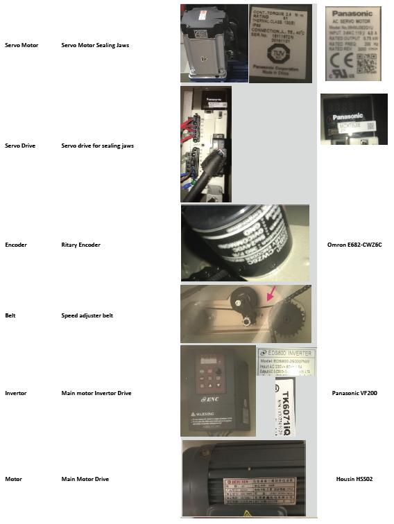
74
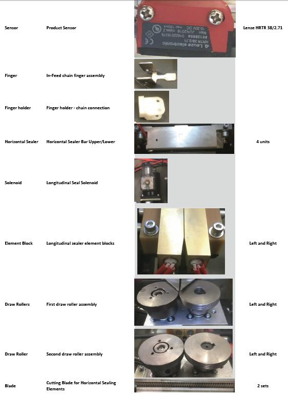
75
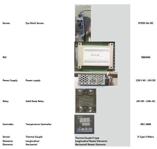
76
Table of Content. Foreword.. 3
 Table of Content Foreword.. 3 1.Safety Precautions.. 3 2.Machine description 2.1.Machine application.4 2.2.Structural features 4 2.3.Machine outline and names for each part...4 2.4.Positions and names
PSC300 Operation Manual
 PSC300 Operation Manual Version 9.10 General information Prior to any attempt to operate this Columbia PSC 300, operator should read and understand the complete operation of the cubing system. It is very
Label Applicator HERMA 400
 Label Applicator HERMA 400 Info GB V6.0 / 30.3.07 [ Facts & Data ] R Constructional variant Right-hand or left-hand version, always flexible to use L Power supply / Line voltage Max. power consumption
Intelligent Pendulum Hardness Tester BEVS 1306 User Manual
 Intelligent Pendulum Hardness Tester BEVS 1306 User Manual Please read the user manual before operation. PAGE 1 Content 1. Company Profile... 3 2. Product Introduction... 3 3. Operation Instruction...
The supreme discipline
 The supreme discipline Automatic film sealing machines The automatic film-sealing machines fulfil the most diverse performance requirements. The bottom seam automatic bag machines manufacture large item
SIMET AVIKO D INSTRUCTION MANUAL SORTING Solutions, Ltd.
 SIMET AVIKO D INSTRUCTION MANUAL 1870 SORTING Solutions, Ltd. 1. TABLE OF CONTENTS 1. TABLE OF CONTENTS...1 2. INTRODUCTION...2 2.1. Application...2 2.2. Operating Conditions...2 2.3. Electro - Optical
Series 1100 ColorTS Servo Manual Registration System
 Series 1100 ColorTS Servo Manual Registration System 400 Oser Avenue Hauppauge NY 11788 631 434 3700 phone 631 434 3718 fax www.empregister.com December 14, 2005 TABLE OF CONTENTS TABLE OF CONTENTS...
Rapid-Air. Operating Instructions. C-T-L w/ 100D Series Servo Feed Control Ver. C. s/n & Later
 Rapid-Air Operating Instructions C-T-L w/ 100D Series Servo Feed Control Ver. C s/n 133095 & Later 4601 Kishwaukee Street, Rockford, IL 61109 815.397.2578 www.rapidair.com Thank you for purchasing a Rapid-Air
Vibratory Deck Sieves 15 in. (380 mm)
") Instruction Sheet P/N 1604433-01 Vibratory Deck Sieves 15 in. (380 mm) Introduction This instruction sheet covers the vibratory deck sieves listed in the following tables. 15-Inch Deck Sieves with 2.5
Instruction Sheet P/N 1604433-01 Vibratory Deck Sieves 15 in. (380 mm) Introduction This instruction sheet covers the vibratory deck sieves listed in the following tables. 15-Inch Deck Sieves with 2.5
Model DT-311J. And DT-311J-230V(AC) DIGITAL STROBOSCOPE INSTRUCTION MANUAL
 DIGITAL STROBOSCOPE INSTRUCTION MANUAL") Test Equipment Depot - 800.517.8431-99 Washington Street Melrose, MA 02176 - TestEquipmentDepot.com Model DT-311J And DT-311J-230V(AC) DIGITAL STROBOSCOPE INSTRUCTION MANUAL 1. GENERAL The DT-311J DIGITAL
Test Equipment Depot - 800.517.8431-99 Washington Street Melrose, MA 02176 - TestEquipmentDepot.com Model DT-311J And DT-311J-230V(AC) DIGITAL STROBOSCOPE INSTRUCTION MANUAL 1. GENERAL The DT-311J DIGITAL
Wired Troubleshooting Manual
 Wired Troubleshooting Manual Congratulations on your choice of this product. Its superior sound reproduction will provide enjoyment and entertainment. We appreciate your patronage and take pride in the
1-Touch Vibratory Sieve Shaker SS-10
 1-Touch Vibratory Sieve Shaker SS-10 Safety Instructions WARNING!! This machine operates on electric current. Improper operation could result in electrical shock, electrocution, or an explosion! 1. ALWAYS
TRF STEP-DOWN TRANSFORMER USER MANUAL
 TRF STEP-DOWN TRANSFORMER USER MANUA www.ventilation-system.com 2013 ! WARNING The present operation manual consisting of the technical details, operating instructions and technical specification applies
Field Service Procedure Replacement PCU Kit, Coastal
 1. Brief Summary: Troubleshooting document for diagnosing a fault with and replacing the PCU assembly on the coastal series antennas. 2. Checklist: Initialization Rate Sensor Outputs Run the Built In Test
READ ME FIRST. Touchstone TV Lift
 Whisper Lift II PRO 2 READ ME FIRST 1. After completing the unpacking and uncrating of the cabinet, you will find the Owner s Manual, TV, installation hardware, and the wireless remote all together and
Index. Index. 1.0 Introduction...2 This Manual Operation Finger Lift Cable Lift Pneumatic Operation...
 Li nearenc oder s wi t httlout put Us ermanual Index 1.0 Introduction..........................2 This Manual...........................2 2.0 Safety Summary......................3 Terms in this Manual....................3
OWNERS MANUAL. Revision /01/ Lightronics Inc. 509 Central Drive Virginia Beach, VA Tel
 OWNERS MANUAL Revision 1.8 09/01/2002 OWNERS MANUAL Page 2 of 12 AR-1202 UNIT DESCRIPTION The AR-1202 consists of a processor and 12 dimmer channels of 2.4KW each. Each dimmer channel is protected by a
AUTOMATIC TAPING MACHINE INSTRUCTION MANUAL TAIYO SEIKI CO., LTD.
 - AUTOMATIC TAPING MACHINE INSTRUCTION MANUAL TAIYO SEIKI CO., LTD. 1 Contents CONTENTS 1. Introduction... 2 1-1. Important safety notice...2 1-2. Precautions for use and installation...2 1-3. Operating
High Performance (Gold Plus) Spliceable Tape Feeder Part Number: Part Number: Revision 3 Jun 2008 No.
 Spliceable Tape Feeder Part Number: Part Number: Revision 3 Jun 2008 No.") 8mm High Performance (Gold Plus) Spliceable Tape Feeder Part Number: 50934707 12mm High Performance (Gold Plus) Spliceable Tape Feeder Part Number: 50934807 Revision 3 Jun 2008 No. 0930D-E010 i Table
8mm High Performance (Gold Plus) Spliceable Tape Feeder Part Number: 50934707 12mm High Performance (Gold Plus) Spliceable Tape Feeder Part Number: 50934807 Revision 3 Jun 2008 No. 0930D-E010 i Table
DLP ANTENNA INSTRUCTION MANUAL. Dielectric LLC 22 Tower Road Raymond, Maine Phone:
 DLP ANTENNA INSTRUCTION MANUAL Dielectric LLC 22 Tower Road Raymond, Maine 04071 Phone: 800-341-9678 TABLE OF CONTENTS Section Title Page Warnings 1 Return Policy. 1 Factory Tests... 1 Antenna Description....
Blown Film Extrusion. Line Control. 5 Layers CD Series IBC Temperature USER MANUAL
 Blown Film Extrusion Line Control 5 Layers CD Series IBC Temperature USER MANUAL P.O.B. 1122 Afula Illit 18550, Israel Tel: +972-4-6405857 Fax: +972-4-6405911 info@sysmetric-ltd.com Manual Number: 5CDIT102
INSTRUCTION AND MAINTENANCE VIDEO MOTORE PROJECTION SCREEN
 INSTRUCTION AND MAINTENANCE VIDEO MOTORE PROJECTION SCREEN 1.1 TECHNICAL DATA PRODUCT DESCRIPTION Screens made with the following projection fabrics: SOFT WHITE, MATT WHITE SOFT, SOFT WHITE TRANSOUND,
Installation Manual Original Instructions - IW4001
 Installation Manual Original Instructions - IW4001 Installation Manual 1 General Operator and Supervisor Information Signal Word Definition Signal Word Panel Table of Contents Operator and Supervisor Information
High Performance DL-60 (Gold Plus) (7 in - 13 in) Dual Lane Spliceable Tape Feeder Part Number: Revision 3 Sep No.
 (7 in - 13 in) Dual Lane Spliceable Tape Feeder Part Number: Revision 3 Sep No.") 8mm High Performance DL-60 (Gold Plus) (7 in - 13 in) Dual Lane Spliceable Tape Feeder Part Number: 50381212 Revision 3 Sep. 2010 No. 0730D-E043 Page i Table of Contents Functional Description...1 Procedures
8mm High Performance DL-60 (Gold Plus) (7 in - 13 in) Dual Lane Spliceable Tape Feeder Part Number: 50381212 Revision 3 Sep. 2010 No. 0730D-E043 Page i Table of Contents Functional Description...1 Procedures
Caution. Hanging the Screen:
 Installation Instructions for Laminar and Laminar XL Projection Screens Caution 1. Read Instructions through completely before proceeding; keep them for future reference. Follow these instructions carefully.
BEAM MOVING HEAD YODN Lamp. 132W 2R MOVING HEAD Brightness / Stability USER MANUAL. Version 1.0 beta
 BEAM MOVING HEAD YODN Lamp W R MOVING HEAD Brightness / Stability This product manual contains important information about the safe installation and use of this projector. Please read and follow these
INSTALATION PROCEDURE
 INSTALLATION PROCEDURE Overview The most difficult part of an installation is in knowing where to start and the most important part is starting in the proper start. There are a few very important items
PLL2210MW LED Monitor
 PLL2210MW LED Monitor USER'S GUIDE www.planar.com Content Operation Instructions...1 Safety Precautions...2 First Setup...3 Front View of the Product...4 Rear View of the Product...5 Quick Installation...6
Flat-Bed Module Recorders
 Flat-Bed Module Recorders Model No. 08376-50 08376-55 08376-60 0115-0192 4/28/00 Table of Contents Introduction...3 Power Requirements...3 Chart Paper Installation...3 Pen Installation...5 Grounding...5
Operating instructions Retro-reflective sensor. OJ50xx laser / / 2010
 Operating instructions Retro-reflective sensor OJ50xx laser 70481 / 00 05 / 010 Contents 1 Preliminary note3 1.1 Symbols used 3 Safety instructions 3 4 Installation 4 4.1 Installation of the supplied mounting
Safety Precautions and Maintenance
 Safety Precautions and Maintenance 1. Unplug the monitor before cleaning it with a slightly damp cloth. 2. Wiping the screen with a dry cloth is recommendable, and only during the power has been switched
Model 5240 Digital to Analog Key Converter Data Pack
 Model 5240 Digital to Analog Key Converter Data Pack E NSEMBLE D E S I G N S Revision 2.1 SW v2.0 This data pack provides detailed installation, configuration and operation information for the 5240 Digital
03-Durchfuehren_RZ_0708_EN.qxd:03-Durchfuehren GB.qxd :06 Uhr Seite 200 Feed-through
 Feed-through Feed-through FEED-THROUGH Series Size Page Rotary Feed-through for Robots DDF 202 DDF 031 206 DDF 040 208 DDF 040-1 210 DDF 050 212 DDF 050-1 214 DDF 063 216 DDF 080 218 DDF 080-1 220 DDF
8mm PrecisionPro (Green) DL Spliceable 7-13 Tape Feeder. T Rev. B hd This document supports assembly Rev. -
 DL Spliceable 7-13 Tape Feeder. T Rev. B hd This document supports assembly Rev. -") 8mm PrecisionPro (Green) DL Spliceable Tape Feeder 8mm PrecisionPro (Green) DL Spliceable Tape Feeder 8mm PrecisionPro (Green) DL Spliceable Tape Feeder 8mm PrecisionPro (Green) DL Spliceable 7-13 Tape
8mm PrecisionPro (Green) DL Spliceable Tape Feeder 8mm PrecisionPro (Green) DL Spliceable Tape Feeder 8mm PrecisionPro (Green) DL Spliceable Tape Feeder 8mm PrecisionPro (Green) DL Spliceable 7-13 Tape
Colour Explosion Proof Video Camera USER MANUAL VID-C
 Colour Explosion Proof Video Camera USER MANUAL VID-C Part Number: MAN-0036-00 Rev 4 Copyright 2002 Net Safety Monitoring Inc. Printed in Canada This manual is provided for informational purposes only.
Model 5250 Five Channel Digital to Analog Video Converter Data Pack
 Model 5250 Five Channel Digital to Analog Video Converter Data Pack E NSEMBLE D E S I G N S Revision 3.1 SW v2.0.1 This data pack provides detailed installation, configuration and operation information
Three Axis Digital Readout System
 NEWALL MEASUREMENT SYSTEMS C80 Three Axis Digital Readout System CONTENTS 2 SPECIFICATIONS 3 CONNECTIONS 4 MOUNTING 4 Arm Mounting (Non-adjustable) 4 Arm Mounting (Adjustable) 5 Face Mounting (Adjustable)
General Specifications
 General Specifications WG41F11C Compact O Frame GS 14M04B10-20E-Z1 [Style: S1] Overview The WG41F11C Compact O frame is a space-saving frame designed for coating lines of battery electrode sheets. This
LED Spot Light User Manual Model LS90 Big Dipper Laser Science And Technology Co., Ltd Please read this manual carefully before operating
 LED Spot Light User Manual Model:LS90 Big Dipper Laser Science And Technology Co., Ltd REV: 1.01 Please read this manual carefully before operating Warnings: Please check the package whether any damage
Operating Instructions
 CNTX Contrast sensor Operating Instructions CAUTIONS AND WARNINGS SET-UP DISTANCE ADJUSTMENT: As a general rule, the sensor should be fixed at a 15 to 20 angle from directly perpendicular to the target
In-Ceiling Electric Motorized Front Projection Screen Evanesce Series. User s Guide
 In-Ceiling Electric Motorized Front Projection Screen Evanesce Series User s Guide Important Safety & Warning Precautions Make sure to read this user s guide and follow the procedures below. Caution: The
VPM2. Operator's Manual
 VPM2 Operator's Manual Whip Mix Corporation 361 Farmington Ave. P.O. Box 17183 Louisville, KY 40217-0183 USA 502-637-1451 800-626-5651 Fax 502-634-4512 www.whipmix.com Features The Whip Mix VPM2 is designed
Instruction Manual. Universal Flow Controller Model 261 / 261-EC-01
 Universal Flow Controller Model 261 / 261-EC-01 Instruction Manual Type ARS 261-EC 01 Art.-no: 82212264 Table of Contents 1. Safety Instructions 2. Product ID - Dimensions 3. Function Description 4. Installation
ivw-fd122 Video Wall Controller MODEL: ivw-fd122 Video Wall Controller Supports 2 x 2 Video Wall Array User Manual Page i Rev. 1.
 MODEL: ivw-fd122 Video Wall Controller Supports 2 x 2 Video Wall Array User Manual Rev. 1.01 Page i Copyright COPYRIGHT NOTICE The information in this document is subject to change without prior notice
PERFORMANCE, PACKAGED FLEXIBLES VERTICAL PACKAGING SOLUTIONS THAT FIT
 PERFORMANCE, PACKAGED FL FLEXIBLES VERTICAL PACKAGING SOLUTIONS THAT FIT YOUR PRODUCT. YOUR BUDGET. YOUR NEEDS. PACKAGING SOLUTIONS FOR OVER 40 YEARS Rennco manufactures a full line of vertical packaging
SPECIFICATION NO Model 207 Automatic GTAW Welding System
 1.0 Introduction The Model 207 is a completely self-contained Gas Tungsten Arc Welding (GTAW) System requiring only input power, inert gas and AMI Welding Head (or manual torch) for operation. Its small
MultiMac. Eddy Current Instrument for Encircling Coil, Sector and Rotary Probe Testing of Tube, Bar, & Wire
 MultiMac Eddy Current Instrument for Encircling Coil, Sector and Rotary Probe Testing of Tube, Bar, & Wire Inspection Features Versatile Threshold Selection Challenging test conditions are made simple
8000 Plus Series Safety Light Curtain Installation Sheet ( CD206A/ CD206B )
") SMARTSCAN 8000 PLUS LIGHT CURTAIN 1 Unpacking 8000 Plus Series Safety Light Curtain Installation Sheet ( CD206A/0160306 CD206B160306 ) Remove all packaging material and retain it Locate and keep the delivery
SMARTSCAN 8000 PLUS LIGHT CURTAIN 1 Unpacking 8000 Plus Series Safety Light Curtain Installation Sheet ( CD206A/0160306 CD206B160306 ) Remove all packaging material and retain it Locate and keep the delivery
INSTRUCTION & INSTALLATION GUIDE
 Digital electric radiator INSTRUCTION & INSTALLATION GUIDE 2 Introduction harmoni digital electric radiators are programmable with an exclusive electronic temperature programmer and manufactured with quality
3.22 Finalize exact specifications of 3D printed parts.
 3.22 Finalize exact specifications of 3D printed parts. This is the part that connect between the main tube and the phone holder, it needs to be able to - Fit into the main tube perfectly - This part need
2.4 METER SERIES 1250 ANTENNA SYSTEM
 June 1,2009 Revision B Assembly Manual 2.4 METER SERIES 1250 ANTENNA SYSTEM General Dynamics SATCOM Technologies 1500 Prodelin Drive Newton NC 28658 2.4 Meter 2 Piece Az/El Installation Instructions B
MICROMASTER Encoder Module
 MICROMASTER Encoder Module Operating Instructions Issue 01/02 User Documentation Foreword Issue 01/02 1 Foreword Qualified Personnel For the purpose of this Instruction Manual and product labels, a Qualified
Motor Operated Solar Shade with Valance Installation and Care Instructions Complete Video Instructions Available Online at
 * Motor Operated Solar Shade with Valance Installation and Care Instructions Complete Video Instructions Available Online at www.keystonefabrics.com Step 1: Identify the parts of your shade (parts shown
USER S Manual NGLT104WPD NGLT150WPD LCD TV / Monitor (IP67 Grade)
") USER S Manual NGLT104WPD NGLT150WPD LCD TV / Monitor (IP67 Grade) This Manual is revisable without further notice Contents CONTENTS ------------------------------------------------------------------- 1
USER S Manual NGLT104WPD NGLT150WPD LCD TV / Monitor (IP67 Grade) This Manual is revisable without further notice Contents CONTENTS ------------------------------------------------------------------- 1
INSTRUCTIONAL MANUAL FOR LCD ZOOM MICROSCOPE
 INSTRUCTIONAL MANUAL FOR LCD ZOOM MICROSCOPE ? 8 LCD Screen? 10.4 LCD Screen LCD Zoom Microscope Instruction Manual Please read the Instruction Manual carefully before installation and keep it for future
Website: Tel: ADDRESS: 6475 Las Positas Rd. Livermore, CA Item No. E5B/E5S Installation Guide
 Website: www.flexispot.com Tel: -855-4-808 ADDRESS: 6475 Las Positas Rd. Livermore, CA 9455 Item No. E5B/E5S Installation Guide Specifications Step Column 3 Max. Weight Capacity 0 Ibs (00 kg) Speed 38mm/s
DP1 DYNAMIC PROCESSOR MODULE OPERATING INSTRUCTIONS
 DP1 DYNAMIC PROCESSOR MODULE OPERATING INSTRUCTIONS and trouble-shooting guide LECTROSONICS, INC. Rio Rancho, NM INTRODUCTION The DP1 Dynamic Processor Module provides complete dynamic control of signals
19 / 20.1 / 22 WIDE SCREEN TFT-LCD MONITOR
 19 / 20.1 / 22 WIDE SCREEN TFT-LCD MONITOR V193/ V220 Series V202 Series USER MANUAL www.viewera.com Rev. 2.0 Table of Contents EMC Compliance......1 Important Precautions...2 1. Package contents....3
LITE-ON TECHNOLOGY CORPORATION
 Features * Lead (Pb) free product RoHS compliant. * Low power consumption. * High efficiency. * Versatile mounting on p.c. board or panel. * I.C. compatible/low current requirement. * Popular T-1 diameter.
SceneStyle2 User Guide
 SceneStyle2 User Guide Mode Lighting (UK) Limited. The Maltings, 63 High Street, Ware, Hertfordshire, SG12 9AD, UNITED KINGDOM. Telephone: +44 (0) 1920 462121 Facsimile: +44 (0) 1920 466881 e-mail: website:
Winmate Communication INC.
 20.1 Military Grade Display Model: R20L100-RKA2ML User s Manual Winmate Communication INC. May, 2011 1 IMPORTANT SAFETY INSTRUCTIONS Please read these instructions carefully before using the product and
PL2410W LCD Monitor USER'S GUIDE.
 PL2410W LCD Monitor USER'S GUIDE www.planar.com Content Operation Instructions...1 Safety Precautions...2 First Setup...3 Front View of the Product...4 Rear View of the Product...5 Quick Installation...6
ORM0022 EHPC210 Universal Controller Operation Manual Revision 1. EHPC210 Universal Controller. Operation Manual
 ORM0022 EHPC210 Universal Controller Operation Manual Revision 1 EHPC210 Universal Controller Operation Manual Associated Documentation... 4 Electrical Interface... 4 Power Supply... 4 Solenoid Outputs...
Operating Manual. Automated Gear. Apollo Design Technology, Inc Fourier Drive Fort Wayne, IN USA
 Operating Manual Automated Gear Apollo Design Technology, Inc. 4130 Fourier Drive Fort Wayne, IN 46818 USA PH: +01(260)497-9191 FX: +01(260)497-9192 www.apollodesign.net 11-25-09 5-6 POWERING UP THE RIGHT
Modular Lube Lubrication Systems System Controls
 Model 84501 Program Timer Solid State Designed to control the lubrication cycle frequency of air-operated single-stroke pumps. Timer turns pump on/off at programmed intervals via a 3-way or 4-way air solenoid
Saddle-stitching System StitchLiner5500
 Saddle-stitching System StitchLiner5500 Combining the efficiency and ease of operation of flat sheet collating with the productivity, versatility and quality of a saddle-stitching system. The StitchLiner5500
Instruction manual. KUZMA 4POINT 14 inch TONEARM Serial Number:
 Instruction manual KUZMA 4POINT 14 inch TONEARM Serial Number:.. 2016-09 1 KUZMA LTD INSTRUCTION MANUAL FOR 4POINT 14 tonearm The 4POINT 14 tonearm is a very precisely engineered piece of equipment, however,
2100, 2200, 4100, 6200, MPB Series Side Mount Drive Package for Light Load 60 Hz Gearmotors
 00, 00, 400, 600, MPB Series Side Mount Drive Package for Light Load 60 Hz Gearmotors Installation, Maintenance & Parts Manual DORNER MFG. CORP. INSIDE THE USA OUTSIDE THE USA P.O. Box 0 975 Cottonwood
Installation / Set-up of Autoread Camera System to DS1000/DS1200 Inserters
 Installation / Set-up of Autoread Camera System to DS1000/DS1200 Inserters Written By: Colin Langridge Issue: Draft Date: 03 rd July 2008 1 Date: 29 th July 2008 2 Date: 20 th August 2008 3 Date: 02 nd
Orbit TM DIGITAL SHAKERS
 Orbit TM DIGITAL SHAKERS INSTRUCTION MANUAL Models P2, P4, M60, 300, 1000, 1900 Labnet International PO Box 841 Woodbridge, NJ 07095 Phone: 732 417-0700 Fax: 732 417-1750 email: labnet@labnetlink.com 2
DLP200M 2 Relay Module for Heating and Cooling Plants
 Product Sheet TH6.24 Thermostat Type DLP200M DLP200M 2 Relay Module for Heating and Cooling Plants The DLP 200 M is a relay module for activation of loads (namely thermal actuators or circulators) in wireless
Elcometer Circular Ball Type. Drying Time Recorder. Operating Instructions
 English Elcometer 5500 Circular Ball Type Drying Time Recorder Operating Instructions English The Elcometer 5500 Circular Ball Type Drying Time Recorder has been tested in accordance with EU Regulations
User Manual 15" LCD Open frame SAW Touch Monitor KOT-0150US-SA4W. Table of Contents
 User Manual 15" LCD Open frame SAW Touch Monitor KOT-0150US-SA4W Table of Contents Chapter 1. Introduction...2 1.1 Product Description 1.2 About the Product Chapter 2. Installation and Setup...2 2.1 Unpacking
ART2000i Digital Dimming System. Installation guide. Stock number *8200-
 ART2000i Digital Dimming System Installation guide Stock number 8200-0159 *8200- 0159* Useful Avolites phone numbers:- Avolites England Sales and service* (+44) (0) 20 8965 8522 Service out of hours* (+44)
TRANSCENSION 6-CHANNEL DMX DIMMER PACK (order code: BOTE40) USER MANUAL
 USER MANUAL") www.prolight.co.uk TRANSCENSION 6-CHANNEL PACK (order code: BOTE40) USER MANUAL SAFETY WARNING FOR YOUR OWN SAFETY, PLEASE READ THIS USER MANUAL CAREFULLY BEFORE YOUR INITIAL START-UP! CAUTION! Keep this
www.prolight.co.uk TRANSCENSION 6-CHANNEL PACK (order code: BOTE40) USER MANUAL SAFETY WARNING FOR YOUR OWN SAFETY, PLEASE READ THIS USER MANUAL CAREFULLY BEFORE YOUR INITIAL START-UP! CAUTION! Keep this
1.8 METER SERIES 1183 Az/El MOUNT ANTENNA SYSTEM
 REVISION G January 11, 2002 ASSEMBLY MANUAL 1.8 METER SERIES 1183 Az/El MOUNT ANTENNA SYSTEM PRODELIN CORPORATION 1500 Prodelin Drive Newton NC 28658 1.8 METER SERIES 1183 Az/El MOUNT ANTENNA SYSTEM G
DCL9AW. User Manual. English
 DCL9AW User Manual English PRECAUTIONS Information for users applicable in European Union countries 1 Information for users applicable in United States of America 1 Installation 1 Power connection 1 Maintenance
Operating Instructions 07/2007 Edition. SINAMICS G130/G150 Line harmonics filter. sinamics
 Operating Instructions 07/2007 Edition SINAMICS G130/G150 Line harmonics filter sinamics s Safety information 1 General 2 SINAMICS SINAMICS G130/G150 Operating Instructions Mechanical installation 3 Electrical
USER MANUAL. 28" 4K Ultra HD Monitor L28TN4K
 USER MANUAL 28" 4K Ultra HD Monitor L28TN4K TABLE OF CONTENTS 1 Getting Started 2 Control Panel/ Back Panel 3 On Screen Display 4 Technical Specs 5 Care & Maintenance 6 Troubleshooting 7 Safety Info &
VPM2. Operation Manual
 VPM2 Operation Manual Whip Corporation 361 Farmington Ave. P.O. Box 17183 Louisville, KY 40217-0183 USA 502-637-1451 800-626-5651 Fax 502-634-4512 www.whipmix.com LISTED Features The Whip VPM2 is designed
Renishaw Ballbar Test - Plot Interpretation - Mills
 Haas Technical Documentation Renishaw Ballbar Test - Plot Interpretation - Mills Scan code to get the latest version of this document Translation Available This document has sample ballbar plots from machines
A COMPUTERIZED SYSTEM FOR THE ADVANCED INSPECTION OF REACTOR VESSEL STUDS AND NUTS BY COMBINED MULTI-FREQUENCY EDDY CURRENT AND ULTRASONIC TECHNIQUE
 More Info at Open Access Database www.ndt.net/?id=18566 A COMPUTERIZED SYSTEM FOR THE ADVANCED INSPECTION OF REACTOR VESSEL STUDS AND NUTS BY COMBINED MULTI-FREQUENCY EDDY CURRENT AND ULTRASONIC TECHNIQUE
ALO 030 MKII. 30 Watt DMX LED scanner. User manual
 ALO 030 MKII 30 Watt DMX LED scanner User manual Safety instructions WARNING! Always keep this device away from moisture and rain! Hazardous electrical shocks may occur! WARNING! Only connect this device
3 Cleaning. 4 Technical data
 EXC+ EXC- Sig- SIG+ SEN- SEN+ 2.4 Attaching cable to the analog board Attaching cable of the weighing cell to the system solution Connect the cable to the appropriate terminal strip of the Ex1 system solution
SCREEN WINCH SYSTEM INSTALLATION MANUAL FOR SCREENS FROM 300 cm. UP TO 450 cm. of width
 SCREEN WINCH SYSTEM INSTALLATION MANUAL FOR SCREENS FROM 300 cm. UP TO 450 cm. of width Before installing the screen winch system, please read the following instructions carefully: The screen winch system
2100/2200/4100/6200 & MPB Series Bottom Mount Drive Pack. for Standard Load Parallel Shaft 60 Hz Gearmotors
 00/00/400/600 & MPB Series Bottom Mount Drive Pack. for Standard Load Parallel Shaft 60 Hz Gearmotors Installation, Maintenance & Parts Manual DORNER MFG. CORP. INSIDE THE USA OUTSIDE THE USA P.O. Box
EDL8 Race Dash Manual Engine Management Systems
 Engine Management Systems EDL8 Race Dash Manual Engine Management Systems Page 1 EDL8 Race Dash Page 2 EMS Computers Pty Ltd Unit 9 / 171 Power St Glendenning NSW, 2761 Australia Phone.: +612 9675 1414
USER MANUAL. 27 Full HD Widescreen LED Monitor L27ADS
 USER MANUAL 27 Full HD Widescreen LED Monitor L27ADS TABLE OF CONTENTS 1 Getting Started 2 Control Panel/ Back Panel 3 On Screen Display 4 Technical Specs 5 Care & Maintenance 6 Troubleshooting 7 Safety
Operating instructions Through-beam sensor. OJ51xx laser / / 2010
 Operating instructions Through-beam sensor OJ5xx laser 70480 / 00 05 / 200 Contents Preliminary note. Symbols used 2 Safety instructions Functions and features 4 4 Installation 4 5 Electrical connection5
ACCESSORIES MANUAL PART NUMBER: TNP500. Universal Tilt N Plug Interconnect Box USER'S GUIDE
 MANUAL PART NUMBER: 400-0091-003 TNP500 Universal Tilt N Plug Interconnect Box USER'S GUIDE INTRODUCTION Your purchase of the TNP100 Tilt N Plug Interconnect Box is greatly appreciated. We are sure you
INSTALLATION MANUAL. ST-CVTMD420-WPIR-W Covert Motion Detection Color Camera. v1.3 8/11/11 1
 INSTALLATION MANUAL ST-CVTMD420-WPIR-W Covert Motion Detection Color Camera v1.3 8/11/11 1 PACKAGE CONTENTS This package contains: One ST-CVTMD420-WPIR-W covert motion detection camera One installation
PLL1920M LED LCD Monitor
 PLL1920M LED LCD Monitor USER'S GUIDE www.planar.com Content Operation Instructions...1 Safety Precautions...2 First Setup...3 Front View of the Product...4 Rear View of the Product...5 Installation...6
VITEK VTM-TLM191 VTM-TLM240
 VTM-TLM191 VTM-TLM240 19 & 24 Professional LED Monitors with HDMI, VGA, and Looping BNC VITEK FEATURES 19 & 24 Wide Screen LED Display Panel HDMI, VGA, and Looping BNC Composite Video Inputs & Stereo Audio
LED Thunder S-150 Code 1097
 LED Thunder S-150 Code 1097 User Manual 1 1 SAFETY INSTRUCTIONS This device has left the factory in perfect condition. In order to maintain this condition and to ensure a safe operation, it is absolutely
1.5mm amplitude at 10 to 55Hz frequency in each X, Y, Z direction for 2 hours 500m/s² (approx. 50G) in each X, Y, Z direction for 3 times
 in each X, Y, Z direction for 3 times") Color Mark Color Mark Feature Outstanding color matching accuracy - RGB light emitting diodes and 12-bit resolution - 2 detection modes (color only / color + intensity) - -step sensitivity adjustment for
Color Mark Color Mark Feature Outstanding color matching accuracy - RGB light emitting diodes and 12-bit resolution - 2 detection modes (color only / color + intensity) - -step sensitivity adjustment for
Up to 85% higher Service Life due to efficient sealing method.
 Robot Accessories Feeding through Up to 85% higher Service Life due to efficient sealing method. 346 Robot Accessories Feeding through Feeding through DDF 2 Rotary Feed-through Series Size Page DDF 2 348
Dancer control slims down while gaining functionality
 Dancer control slims down while gaining functionality Delta Servo drives with onboard control plus integrated HMI eliminate the need for a PLC on a film handling module. When Company X decided to build
USER MANUAL. 27 Full HD Widescreen LED Monitor L270E
 USER MANUAL 27 Full HD Widescreen LED Monitor L270E TABLE OF CONTENTS 1 Getting Started 2 Control Panel/ Back Panel 3 On Screen Display 4 Technical Specs 5 Care & Maintenance 6 Troubleshooting 7 Safety
USER MANUAL. 22" Class Slim HD Widescreen Monitor L215DS
 USER MANUAL 22" Class Slim HD Widescreen Monitor L215DS TABLE OF CONTENTS 1 Getting Started Package Includes Installation 2 Control Panel / Back Panel Control Panel Back Panel 3 On Screen Display 4 Technical
Cambridge International Examinations Cambridge International General Certificate of Secondary Education
 Cambridge International Examinations Cambridge International General Certificate of Secondary Education *5003676564* DESIGN AND TECHNOLOGY 0445/42 Paper 4 Systems and Control May/June 2015 1 hour Candidates