The CRT-Based Oscilloscope
|
|
|
- Gervais Lawson
- 5 years ago
- Views:
Transcription
1 The CRT-Based Oscilloscope The Basic Mysteries Patrick Jankowiak KD5OEI
2 Knowledge to be Covered What the Oscilloscope Does For You Introduction to the CRT CRT Components The Electron Gun Electrostatic Deflection Plates Post-Deflection Accelerator Operating a CRT Considerations Example CRT the 5ADP1 Creation of Operating Potentials Simple Oscilloscope Practical Block Diagram Sweep Circuits Amplifiers Chop / Alternate Sweep Probes Measuring High Voltages Safety Repair Tips for Scopes Time Permitting: References Hands-on Q&A Free Stuff LCD based digital scopes will not be discussed. 2
3 What the Oscilloscope Does For You The Oscilloscope draws an accurate picture of the variations of a voltage and plots it: Against time. Against another static or varying voltage. Accessories enable it to plot electrical current or trace curves of tubes or transistors. Shows you things about a signal that the finest meter can not. 3
4 Introduction to the CRT The CRT the Heart of the Oscilloscope The rest of the instrument is dedicated to support the CRT. Alone, the CRT is only a high tech ornament. Understanding the CRT is the first step to knowing how the scope works, how to use it, and how to repair it. The CRT is a Linear Accelerator +KV Km/S %C (Newtonian) , , , , , , ,
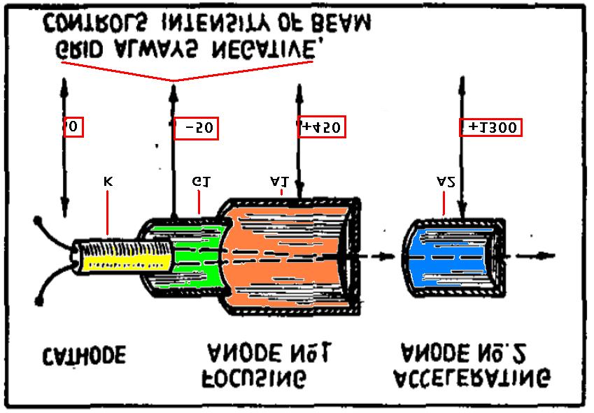
5 CRT Components Electron Gun Heater-Cathode Grid Accelerating Anode (A1) Focus Anode (A2) Electrostatic Deflection Plates PDA / Ultor Anode / A3 (some CRTs) 5


6 The Electron Gun Heater-Cathode Control Grid Accelerating and Focus Anodes comprise the Electrostatic Lens 6


7 The Electron Gun (in simplest CRTs) 7
8 Electrostatic Deflection Plates

9 Post-Deflection Accelerator
10 Operating a CRT Brightness Control varying the voltage on G1 relative to K. G1 negative lower brightness Focus Control varying the voltage on A1 relative to A2. A2 is usually two separate cylinders in modern CRTs, one before A1 and one after A1. Creates the Focus Lens. A2 is responsible for beam acceleration through the deflection plate area. The ultimate brightness is determined by the final accelerating potential, often that of A2 on smaller CRTs. This can be up to about 2,000V relative to K. Limited by socket insulation It is maintaining the correct relationships between the operating voltages that creates a quality electron beam and a well-focused, round spot on the screen. 10
11 Operating Considerations Consideration: The deflection plates must often be +/-300V relative to chassis GND for circuit design reasons, therefore K is often 600V to 2000V negative relative to GND. Consideration: The deflection plates are physically close to A2, A2 is often within +/-300V of the deflection plate average voltage. to prevent arcing prevent distortion of the focused electron beam excessive electrostatic field gradient (parasitic lensing). A3, the Third Anode, is an optional element made of an internal conductive coating and carries the highest potential. It has a terminal on the side of the CRT bell because the socket cannot usually withstand 4000 to 10,000 Volts. Also called the PDA or Ultor Scope CRT can usually function without a much higher voltage on this, but at reduced brilliance. 11

12 Example CRT The 5ADP1
13 Creation of Operating Potentials 13

14 Practical Oscilloscope Block Diagram 14 Return to AC Amplifier
15 Sweep Circuits The clock of the oscilloscope Generates sawtooth signal for horizontal deflection axis Provides calibrated and variable time standard against which to display and measure waveforms Generates blanking signals to turn off beam when not drawing the waveform Can run without trigger, trigger while running, wait for trigger, be manually triggered (one-shot) Can be triggered by AC line, input signal, external signal
16 Sweep Time Constants Generating a sawtooth waveform the easy way: 1. Charge a capacitor through a resistor 2. Quickly discharge the capacitor RC charge curve is nonlinear but the scope needs a linear sweep.

17 Sweep Time Constants Using only a small portion of the charging waveform results in an acceptably linear increase of voltage with time.
18 Sweep Oscillator -Thyratron A thyratron such as the 884 can discharge the capacitor almost instantly depending on circuit constants. In this diagram, current limiting resistor Rb is large and the discharge time is too long for scope use. The 884 has been used in 1-2MHz scopes with H sweep rates up to about 50KHz.
19 Sweep Oscillator-Thyratron Several sweep frequency ranges are made available by selecting different timing capacitors C. 2M resistor R adjusts the frequency continuously within each range.
20 Sweep Oscillator Multivibrator Multivibrators can run much faster than thyratrons and careful design is necessary to achieve a fast discharge.
21 Sweep Oscillator Multivibrator Showing interconnections to H DEFL amplifier, blanking circuit, and trigger circuit Switch selects capacitors from banks C1 and C2. C1 is retrace. C2 is trace.

22 Refined Sweep Circuit
23 Sync / Trigger Circuits
24 Deflection Amplifiers AC Coupled Amplifiers Simple design Low parts count Ease of alignment Ease of repair Cannot amplify a DC voltage Distortion increases at frequencies <100Hz DC Coupled Amplifiers Handle AC, DC and mixed signals accurately No distortion at low frequencies Special measurements possible Complex balanced design 2x-3x the parts count Harder to align and repair
25 AC Coupled Input Attenuator 25
26 DC Coupled Input Attenuator Simple compensated attenuator is much like that in a VTVM or VOM 26
27 DC Coupled Input Attenuator High accuracy attenuator uses separate compensation for decade ( ) and integer (1-2- 5) ranges 27
 28 Refer to")
28 AC Amplifier (balanced deflection) 28 Refer to practical Diagram
29 AC Amplifier Beam Positioning
30 DC Amplifier (solid state)
31 DC Amplifier (tube preamp section)
32 DC Amplifier (tube output section)

33 Chop/Alternate function

34 Synchronized Trace Alternation
35 Common Probes 1:1 straight probe 100V at probe is carried directly to scope input 10:1 probe with compensator 100V at probe is reduced by series resistor to 10V at scope RF detector probe Simple, has built in RF diode detector and network Usually for low RF voltages <50V peak AC Usually good for DC to V (capacitor isolated) Often good to 500MHz Detected envelope (e.g. audio) is delivered to scope Not always calibrated for amplitude Always use the GND.
36 Measuring Voltages to 600V Be certain of scope input voltage limits Usually stated as peak or DC on front panel near input connector Some are 600V, some are 50V, some special are even 5V If not stated, V is usually OK on older tube units. Trigger inputs may have different ratings. What is the voltage rating of the probe? Read the manual. Always use the GND.
37 Measuring High Voltages Special Considerations Would you trust the probe in your hand when you touch it to these test points? 5000V pulse in the tube color TV set? 700V DC+AC in a filter choke input? Anything over 600V peak should never be measured with a standard probe. Arc at the tip. Arc through the probe body Over 600V should only be measured with a probe built or designed for higher voltages. Always use the GND.
38 Measuring High Voltages HV Series Multiplier Probes If scope has 1M input resistance, adding a 9M resistance in series increases resistance to 10M and allows 10X the voltage rating. Commercial series-probes and probe tip adapters are out there. Be aware that if the scope is not grounded to the work, and the tip or probe is not plugged into the scope, arcing may occur. For DIY - Always observe voltage ratings of series resistors. Most resistors are V, some are less. Use nine 1M resistors in series for example. Or buy a special HV resistor Caddock, OhmCraft, Victoreen, Vishay Remember - no compensation with resistors only. Always use the GND.
39 Measuring High Voltages DIY HV Series Multiplier Probes Use nine 1M resistors in series for example. Slip into a glass tube with a tip at the end. Slip the glass tube inside a (brass) metal tube leaving 1 exposed at the tip ( hot ) end. Run coaxial cable from scope plug to housing. Center to cold end of resistor string Shield to tube (housing) and a GND lead Brass tube probe body becomes a metal grounded shield between the high voltage resistor and the operator. ALWAYS have probe attached to scope before probing. Otherwise, HV may arc at loose scope end of cable and back to operator. Always use the GND.
40 Measuring High Voltages DIY High Voltage Divider Probes Same body construction as series probe Increased safety ; integral ground. Assume scope input=1m Use nine 1M resistors in series plus a 500K and a 1M Tip tap-1-GND_lead The scope is tapped to the top of the last 1M resistor. Multiplication is 20:1; 2KV at tip makes 100V at scope. Always use the GND.

41 Measuring Power at Very High Voltages The 7575 Ohm dummy load attached to the modulator has a 7306V p-p audio signal across it, and is also at 3500VDC above ground :1 divider Tip Tap-75-GND. Power of 890W RMS measured using scope to see clipping level and VOM to read volts. Can Do with care. Use external divider and temporarily install to equipment, then attach to tap and GND Space and insulate divider and cables from objects to prevent arcing. Respect wattage and voltage ratings. Always use the GND. Hands-Off measurement Kill-Switch on AC Input Stand well back Observe from distance Light fuse and get away.
42 Isolation and Grounding Safety Scope should always be grounded using AC grounding plug. Some scopes do not have a grounding cord. Connect proper ground wire between the scope and workbench power ground. Your workbench must have an AC power ground. Use isolation transformer on equipment under test. If not appropriate to isolate gear, check for AC leakage from gear and if OK proceed. Noise from bad grounds and ground loops can obscure weak signals. Not a safety issue but an annoyance. Point? Bad things happen to hands, scopes, and signal purity when lots of current flows through the probe ground.
43 Safety High Power Stuff Inside the Scope Bipolar power supplies, +/- 200 to 500VDC Cathodes as well as anodes in DC amplifiers Deflection amplifiers (solid state units as well) Large tube scopes like the Tektronix 545 can deliver 1amp at 600VDC for a few seconds before blowing a fuse. Any CRT connection (Cathode 2KV) Especially the PDA +1.5KV to +20KV
44 Safety CRT Implosion Violent breakage of glass; explosion. Drives fragments toward each other, smashing and scattering in all directions. Eye protection against flying glass. Gloves and apron protect against cuts lbs of atmospheric pressure on a 5 CRT bulb. Cleanup? Fairly harmless, just get all the glass. No mercury, lead, or poison gas Phosphors are basic mineral compounds, just don t eat. Trash OK. Wash hands. Don t break it in the first place.
45 Same problems as radios Scope Repair Caps leaky Resistors out of tolerance Bad tubes Mechanical damage These need not be discussed Special problems Arcing Ozone and corona damage Problems of HV insulators and couplings CRT issues HV supply issues DC amplifier issues
46 Scope Repair Arcing May be seen and heard and snapping white sparks Diagnose quickly, don t let it go on. Clean up area or spots on wire Possibly apply 3M self bonding tape, corona dope, or silicon glue Replace badly burned wire with 5KV or better test lead wire. In some cases wire may need to be 10KV or 20KV rated.
47 Scope Repair Ozone and Corona 2KV to 20KV points Ozone fresh air odor. Faint or very faint hissing sound. Do not stick your ear near it. The hiss is a warning. It will arc. Tiny violet discharge into air, seen in dark. Clean and repair. Remove sharp edges from object. Or cover with insulating compound Insulate with corona dope or silicon glue.
48 Scope Repair Problems of insulators and shaft couplings HV standoffs and enclosures Insulated non-conductive shafts Insulating shaft couplers, u-joints Shafting and couplers often found on intensity and focus pots. Any control that is >500V to GND Dirt is the real enemy Cleaning Scrubbing Wiping with non-residue solvent. Remove carbon tracks if burn has occurred. Cover damaged area.
49 Scope Repair Problems of CRTs Replace it for Internal shorts Dynamic shorts with HV applied Loose internal parts Burn marks on screen Can you live with it? Search for replacement. Heater does not light Neck warm? Check heater voltage Check solder on pins Low emission, poor focus, low brightness Check all operating voltages against instrument manual or CRT manual Standard CRT rejuvenation techniques as last resort
50 HV Supply Issues Scope Repair Check manual for correct potentials Is supply oscillator-driven? Rectifier or voltage multiplier Some have 2 or 3 tubes Open or burned resistors Also check CRT circuit voltage dividers Short on intensity or focus pot? Shorted capacitor Leaky PCB capacitor clean up, bag, dispose in trash OK; EPA definition small PCB capacitor
51 Scope Repair DC Coupled Amplifier Issues Can cause beam to be held off the screen to the side, making it look like the CRT is faulty. Tip: connect all 4 deflection plates together momentarily. Spot should appear on screen. Transistorized units check potentials at each device. Work as if it were an audio power amplifier. Tube units - check all potentials on each tube using the cathode voltage as the (-) VOM lead/reference point. Find missing/wrong voltages Use tube manual as guide if instrument manual is not available. Start at front end and work towards deflection plates. The usual suspects Tubes, Resistors, Capacitors DC amplifier grid and plate voltages change when the position or centering controls are moved. An audio generator is also useful. Using a scope to troubleshoot a scope is a plus.
52 References: Most of the pictures in this presentation were taken from the materials listed here. We owe the authors of these documents a debt for their contributions. It is advisable to study these materials in order to increase one s knowledge of CRT-based oscilloscope technology, use, and maintenance. These documents are available freely on the WWW. THE CATHODE RAY TUBE AT WORK, John Rider Hughes Memo-Scope 104D Instruction Manual, Hughes Aircraft Company Know Your Oscilloscope, Paul C. Smith Troubleshooting With the Oscilloscope, Robert G Middelton Oscilloscope Techniques, Alfred Haas The Cathode-Ray Oscilloscope, Charles Sicuranza Cathode Ray Tube Displays, Louis N Ridenour, MIT Radiation Series V22 Radio and TV Test Instruments, Hugo Gernsback Sylvania 1959 Tube Manual, Sylvania Tektronix 545 Oscilloscope Manual, Tektronix Precision Electronics ES-500 Oscilloscope Manual, Precision Electronics Bell and Howell / Heathkit " Oscilloscope Manual
53 Disclaimer You should assume that all material presented is protected by copyright unless otherwise noted and may not be used except as permitted in these Terms and Conditions. Fair Use of Others' Copyrighted Materials:In cases where the author has made fair use of the copyrighted work of another entity, your use of that information is subject to applicable law just as if you had made use of the original copyrighted work. Your use of the material is at your risk: The author makes no warranties or representations as to its safety or accuracy and The author specifically disclaims any liability or responsibility for any errors or omissions in the content. Neither the author nor any other party involved in creating, producing, or delivering the material is liable for any direct, incidental, consequential, indirect, or punitive damages arising out of your access to, or use of, or inability to use or access, the material. Without limiting the foregoing, the material is provided to you "AS IS" WITHOUT WARRANTY OF ANY KIND, EITHER EXPRESSED OR IMPLIED, INCLUDING, BUT NOT LIMITED TO, THE IMPLIED WARRANTIES OF MERCHANTABILITY, FITNESS FOR A PARTICULAR PURPOSE, OR NON-INFRINGEMENT. Please note that some jurisdictions may not allow the exclusion of implied warranties, so some of the above exclusions may not apply to you. Check your local laws for any restrictions or limitations regarding the exclusion of implied warranties. Features and specifications of products described or depicted in the materials are subject to change at any time without notice. Specifications, weights, safety warnings, and measures are approximate. Some statements or information may be incompetent or even outright lies. All CRT screens are measured diagonally; all screen images are photos or simulated pictures unless otherwise indicated. The author assumes no responsibility, and shall not be liable for, any damages to, or viruses, worms, trojan horses, and or without limitation, any and all destructive files, infernal, and or malicious code that may infect, your computer equipment or other property on account of your access to, use of, or browsing in the material or your possession or use of any materials, data, text, images, video, audio, or viruses, worms, trojan horses, infernal, and or malicious code, and or without limitation, any and all files from the CDROM or DVD, regardless of the initiator, means, or procedure of download. The author assumes no responsibility, and shall not be liable for, any damages to, or destruction, death, personal injury, and or without limitation, any and all inconveniences, losses, immolations, fires, electrocution, rusty nails and broken glass, radiation of any kind including nuclear accidents and X-ray, objects stuck in body parts or walls, other impalements, lacerations, disfigurements, disease including cancer, blindness, insanity; and or LASER, RF damage, burns, and or unpleasant or infernal effects which may harm or destroy, any person, equipment or other property on account of your access to, use of, or browsing in the material and or your obedience to or following of, any materials, ideas, instructions, data, text, images, video, audio, or infernal and or malicious plans, and or without limitation, any and all orders or compulsions from the materials. The term materials also includes for the purpose of disclaimer of liability, all websites in which the author has written any material or posted any files. Possession of the material means that you agree that the author is not responsible for anything from the beginning of time until the end of time. If you do not agree, then you must return or destroy all of the materials at you own expense.
54 Errata Page 13: Grid voltage should be 0 to 220V per tube manual and in the practical example should be 1350 to 1570V. The power supply design voltage could be adjusted to compensate for any difference. Page 14: same corrections as page 13.
55 Questions? Thanks! Free stuff: - DVD with reference materials
OSCILLOSCOPE AND DIGITAL MULTIMETER
 Exp. No #0 OSCILLOSCOPE AND DIGITAL MULTIMETER Date: OBJECTIVE The purpose of the experiment is to understand the operation of cathode ray oscilloscope (CRO) and to become familiar with its usage. Also
CHAPTER 4 OSCILLOSCOPES
 CHAPTER 4 OSCILLOSCOPES 4.1 Introduction The cathode ray oscilloscope generally referred to as the oscilloscope, is probably the most versatile electrical measuring instrument available. Some of electrical
University of Utah Electrical & Computer Engineering Department ECE1050/1060 Oscilloscope
 University of Utah Electrical & Computer Engineering Department ECE1050/1060 Oscilloscope Name:, A. Stolp, 2/2/00 rev, 9/15/03 NOTE: This is a fill-in-the-blanks lab. No notebook is required. You are encouraged
CATHODE-RAY OSCILLOSCOPE (CRO)
") CATHODE-RAY OSCILLOSCOPE (CRO) I N T R O D U C T I O N : The cathode-ray oscilloscope (CRO) is a multipurpose display instrument used for the observation, measurement, and analysis of waveforms by plotting
CATHODE-RAY OSCILLOSCOPE (CRO) I N T R O D U C T I O N : The cathode-ray oscilloscope (CRO) is a multipurpose display instrument used for the observation, measurement, and analysis of waveforms by plotting
CATHODE RAY OSCILLOSCOPE (CRO)
") CATHODE RAY OSCILLOSCOPE (CRO) 4.6 (a) Cathode rays CORE Describe the production and detection of cathode rays Describe their deflection in electric fields State that the particles emitted in thermionic
CATHODE RAY OSCILLOSCOPE (CRO) 4.6 (a) Cathode rays CORE Describe the production and detection of cathode rays Describe their deflection in electric fields State that the particles emitted in thermionic
The Cathode Ray Tube
 Lesson 2 The Cathode Ray Tube The Cathode Ray Oscilloscope Cathode Ray Oscilloscope Controls Uses of C.R.O. Electric Flux Electric Flux Through a Sphere Gauss s Law The Cathode Ray Tube Example 7 on an
RICHLAND COLLEGE School of Engineering Business & Technology Rev. 0 W. Slonecker Rev. 1 (8/26/2012) J. Bradbury
 J. Bradbury") RICHLAND COLLEGE School of Engineering Business & Technology Rev. 0 W. Slonecker Rev. 1 (8/26/2012) J. Bradbury INTC 1307 Instrumentation Test Equipment Teaching Unit 8 Oscilloscopes Unit 8: Oscilloscopes
RICHLAND COLLEGE School of Engineering Business & Technology Rev. 0 W. Slonecker Rev. 1 (8/26/2012) J. Bradbury INTC 1307 Instrumentation Test Equipment Teaching Unit 8 Oscilloscopes Unit 8: Oscilloscopes
Elements of a Television System
 1 Elements of a Television System 1 Elements of a Television System The fundamental aim of a television system is to extend the sense of sight beyond its natural limits, along with the sound associated
CATHODE RAY OSCILLOSCOPE. Basic block diagrams Principle of operation Measurement of voltage, current and frequency
 CATHODE RAY OSCILLOSCOPE Basic block diagrams Principle of operation Measurement of voltage, current and frequency 103 INTRODUCTION: The cathode-ray oscilloscope (CRO) is a multipurpose display instrument
HOM rev. new Heathkit of the Month #87: by Bob Eckweiler, AF6C. Heath of the Month #87 - Heathkit O-Series Oscilloscopes - Part II
 Heathkit of the Month #: by Bob Eckweiler, AF6C! ELECTRONIC TEST EQUIPMENT Heathkit O- through O- Oscilloscopes. Introduction: In the June RF Newsletter the first four Heathkit Oscilloscopes were discussed;
4.9 BEAM BLANKING AND PULSING OPTIONS
 4.9 BEAM BLANKING AND PULSING OPTIONS Beam Blanker BNC DESCRIPTION OF BLANKER CONTROLS Beam Blanker assembly Electron Gun Controls Blanker BNC: An input BNC on one of the 1⅓ CF flanges on the Flange Multiplexer
3B SCIENTIFIC PHYSICS
 B SCIENTIFIC PHYSICS Triode S 11 Instruction sheet 1/15 ALF 1 5 7 1 Guide pin Connection pins Cathode plate Heater filament 5 Grid Anode 7 -mm plug for connecting anode 1. Safety instructions Hot cathode
OPERATING INSTRUCTIONS FOR SYLVANIA. Type I08 Cathode-Ray Oscilloscope. Sylvania Electric Products Inc. Industrial Apparatus. Emporium, Pennsylvania
 OPERATING INSTRUCTIONS FOR SYLVANIA Type I08 Cathode-Ray Oscilloscope Sylvania Electric Products Inc. Industrial Apparatus Plant Emporium, Pennsylvania OPERATING INSTRUCTIONS FOR Sylvania Type 08 Cathode-Ray
Electrical and Electronic Laboratory Faculty of Engineering Chulalongkorn University. Cathode-Ray Oscilloscope (CRO)
") 2141274 Electrical and Electronic Laboratory Faculty of Engineering Chulalongkorn University Cathode-Ray Oscilloscope (CRO) Objectives You will be able to use an oscilloscope to measure voltage, frequency
2141274 Electrical and Electronic Laboratory Faculty of Engineering Chulalongkorn University Cathode-Ray Oscilloscope (CRO) Objectives You will be able to use an oscilloscope to measure voltage, frequency
The tracer - A dual range tester for semiconductors and other components.
 The tracer - A dual range tester for semiconductors and other components. Introduction The Electro resales tracer is a modern implementation of a testing device developed originally to assist service professionals
CR7000. CRT Analyzer & Restorer. Easily Test And Restore CRTs With The Most Complete Tests Available For Added Profit And Security.
 CR7000 CRT Analyzer & Restorer Easily Test And Restore CRTs With The Most Complete Tests Available For Added Profit And Security. S1 New Demands From Higher Performance CRTs Require New Analyzing Techniques
University of Utah Electrical Engineering Department EE1050/1060 Oscilloscope. Name:, Lab TA:
 University of Utah Electrical Engineering Department EE1050/1060 Oscilloscope Name:, Lab TA: A. Stolp, 2/2/00 rev, 9/14/00 NOTE: This is a fill-in-the-blanks lab. No notebook is required. You are encouraged
Physics 123 Hints and Tips
 Physics 123 Hints and Tips Solderless Breadboards All of the analog labs and most of the digital labs will be built on the Proto-Board solderless breadboards. These provide three solderless breadboard
CHAPTER 3 OSCILLOSCOPES AND SIGNAL GENERATOR
 CHAPTER 3 OSCILLOSCOPES AND SIGNAL GENERATOR OSCILLOSCOPE 3.1 Introduction The cathode ray oscilloscope (CRO) provides a visual presentation of any waveform applied to the input terminal. The oscilloscope
Christmas LED Snowflake Project
 Christmas LED Snowflake Project Version 1.1 (01/12/2008) The snowflake is a follow-on from my Christmas star project from a few years ago. This year I decided to make a display using only white LEDs, shaped
DSO138mini Troubleshooting Guide
 DSO138mini Troubleshooting Guide Applicable main board: 109-13800-00I Applicable analog board: 109-13801-00H 1. Frequently Found Problems 1) LCD completely dark. No backlight 2) LCD lights up but no display
S op o e p C on o t n rol o s L arni n n i g n g O bj b e j ctiv i e v s
 ET 150 Scope Controls Learning Objectives In this lesson you will: learn the location and function of oscilloscope controls. see block diagrams of analog and digital oscilloscopes. see how different input
Using an oscilloscope - The Hameg 203-6
 Using an oscilloscope - The Hameg 203-6 What does an oscilloscope do? Setting up How does an oscilloscope work? Other oscilloscope controls Connecting a function generator Microphones audio signals and
INSTRUMENT CATHODE-RAY TUBE
 Instrument cathode-ray tube D14-363GY/123 INSTRUMENT CATHODE-RAY TUBE mono accelerator 14 cm diagonal rectangular flat face internal graticule low power quick heating cathode high brightness, long-life
GA A26497 SOLID-STATE HIGH-VOLTAGE CROWBAR UTILIZING SERIES-CONNECTED THYRISTORS
 GA A26497 SOLID-STATE HIGH-VOLTAGE CROWBAR by J.F. Tooker, P. Huynh, and R.W. Street JUNE 2009 DISCLAIMER This report was prepared as an account of work sponsored by an agency of the United States Government.
The Venerable Triode. The earliest Triode was Lee De Forest's 1906 Audion.
 The Venerable Triode The very first gain device, the vacuum tube Triode, is still made after more than a hundred years, and while it has been largely replaced by other tubes and the many transistor types,
What is the time? Actually a scope-clock. Introduction:
 What is the time? Actually a scope-clock. 2009-Oct.-29 Introduction: This document is for building the MNS (Microcontrollergesteuerte nostalgische Stationsuhr) scope clock project with all the selected
CP-830FP Chassis TX-29E50D TX-29E50D/B TX-29PS12D TX-29PS12F TX-29PS12P SPECIFICATIONS. Order No: PCZ C2
 Order No: PCZ0510103C2 SPECIFICATIONS Power Source: Power Consumption: 220-240V a.c.,50hz 100W Stand-by Power Consumption: 1,5W Aerial Impedance: 75Ω unbalanced, Coaxial Type Receiving System: PAL-I, B/G,
SERVICE AND OPERATION MANUAL
 MTG-XX02XT/XN Publication A. Issue 1 SERVICE AND OPERATION MANUAL MTG- XX02XT/XN OPEN FRAME XVGA COLOR MONITORS MTG-1702XT/XN : 17INCH, FST MTG-1902XT/XN : 19INCH, FST Information in this publication current
KHT 1000C HV-Probe Calibrator. Instruction Manual
 KHT 1000C HV-Probe Calibrator Instruction Manual Copyright 2015 PMK GmbH All rights reserved. Information in this publication supersedes that in all previously published material. Specifications are subject
COHERENCE ONE PREAMPLIFIER
 COHERENCE ONE PREAMPLIFIER OWNER S MANUAL TABLE OF CONTENTS Introduction Features Unpacking Instructions Installation Phono Cartridge Loading Basic Troubleshooting Technical Specifications Introduction
Burlington County College INSTRUCTION GUIDE. for the. Hewlett Packard. FUNCTION GENERATOR Model #33120A. and. Tektronix
 v1.2 Burlington County College INSTRUCTION GUIDE for the Hewlett Packard FUNCTION GENERATOR Model #33120A and Tektronix OSCILLOSCOPE Model #MSO2004B Summer 2014 Pg. 2 Scope-Gen Handout_pgs1-8_v1.2_SU14.doc
Quick Start. RSHS1000 Series Handheld Digital Oscilloscope
 Quick Start RSHS1000 Series Handheld Digital Oscilloscope General Safety Summary Carefully read the following safety precautions to avoid personal injury and prevent damage to the instrument or any products
SERVICE AND OPERATION MANUAL
 MTG-2907TN Publication A. Issue 1 SERVICE AND OPERATION MANUAL MTG- 2907TN OPEN FRAME VGA COLOR MONITORS MTG-2907TN : 29INCH, FST Information in this publication current as of Jun, 2003. Information subject
Service Manual for D9100 Series Digital-Control Color Monitor
 Service Manual for D9100 Series Digital-Control Color Monitor Wells-Gardner Electronics 9500 W. 55 th Street Suite A McCook, Illinois 60525-3605 (708) 290-2100 069X3015-100 Revision: B / E01025 Date: 8-24-00
Brief Description of Circuit Functions. The brief ckt. description of V20 107E5 17 Monitor
 Exhibit 4 Brief Description of Circuit Functions The brief ckt. description of V20 107E5 17 Monitor 0. Functional Block Diagram 1. General Description 2. Description of Circuit Diagram A. Power Supply
INSTRUMENT CATHODE-RAY TUBE
 INSTRUMENT CATHODE-RAY TUBE 14 cm diagonal rectangular flat face domed mesh post-deflection acceleration improved spot quality for character readout high precision by internal permanent magnetic correction
Build A Video Switcher
 Build A Video Switcher VIDEOSISTEMAS serviciotecnico@videosistemas.com www.videosistemas.com Reprinted with permission from Electronics Now Magazine September 1997 issue Copyright Gernsback Publications,
SERVICE AND OPERATION MANUAL
 MTG-XX02SN/SE Publication A. Issue 1 SERVICE AND OPERATION MANUAL MTG- XX02SN/SE OPEN FRAME SVGA COLOR MONITORS MTG-2902SN/SE : 29INCH, FST MTG-3302SN/SE : 33INCH, FST MTG-3802SN/SE : 38INCH, FST Information
LavryBlack Series Model DA10 Digital to Analog Converter
 LavryBlack Series Model DA10 Digital to Analog Converter Lavry Engineering, Inc. P.O. Box 4602 Rolling Bay, WA 98061 http://lavryengineering.com email: techsupport@lavryengineering.com January 14, 2008
Bill of Materials: Super Simple Water Level Control PART NO
 Super Simple Water Level Control PART NO. 2169109 Design a simple water controller in which electrodes are required to sense high and low water levels in a tank. Whenever the water level falls below the
Noise Detector ND-1 Operating Manual
 Noise Detector ND-1 Operating Manual SPECTRADYNAMICS, INC 1849 Cherry St. Unit 2 Louisville, CO 80027 Phone: (303) 665-1852 Fax: (303) 604-6088 Table of Contents ND-1 Description...... 3 Safety and Preparation
If you are using a CRT tester/restorer other than the CR7000 you are likely incorrectly testing today s CRTs and risk damaging every one you restore.
 general analyzing instruments By Paul Nies Tech Disc Multimedia Producer If you are using a CRT tester/restorer other than the CR7000 you are likely incorrectly testing today s CRTs and risk damaging every
NewScope-7A Operating Manual
 2016 SIMMCONN Labs, LLC All rights reserved NewScope-7A Operating Manual Preliminary May 13, 2017 NewScope-7A Operating Manual 1 Introduction... 3 1.1 Kit compatibility... 3 2 Initial Inspection... 3 3
GEKCO SUBCARRIER REFERENCE OSCILLATOR MODEL SRO10 OPERATION/SERVICE MANUAL
 GEKCO MODEL SRO10 SUBCARRIER REFERENCE OSCILLATOR OPERATION/SERVICE MANUAL GEKCO Labs PO Box 642 Issaquah, WA 98027 (425) 392-0638 P/N 595-431 REV 5/98 Copyright c 1998 GEKCO Labs All Rights Reserved Printed
Metal Electrode Meter
 Metal Electrode Meter INSTRUCTION MANUAL FOR Metal Electrode Meter MODEL 2900 Serial # Date PO Box 850 Carlsborg, WA 98324 U.S.A. 360-683-8300 800-426-1306 FAX: 360-683-3525 http://www.a-msystems.com Version
DL-1A. RF dummy load - 50Ω 20W. Assembly manual. Last update: May 1, Thank you for constructing the DL-1A dummy load kit
 DL-1A RF dummy load - 50Ω 20W Assembly manual Last update: May 1, 2016 ea3gcy@gmail.com Updates and news at: www.qsl.net/ea3gcy Thank you for constructing the DL-1A dummy load kit Have fun assembling it
CHAPTER 9. Actives Devices: Diodes, Transistors,Tubes
 CHAPTER 9 Actives Devices: Diodes, Transistors,Tubes 1 The electrodes of a semiconductor diode are known as anode and cathode. In a semiconductor diode, electrons flow from cathode to anode. In order for
WideScreen. Compliant to DO-160D. Document # Rev C. www. rosenaviation.com. www. rosenaviation.com
 7 Model DISPLAY WideScreen Number 7001 www. rosenaviation.com OEM SALES / CORPORATE OFFICE 1020 Owen Loop South Eugene, OR 97402 1-888-668-4955 Fax (541) 342-4912 DEALER & OPERATOR SALES 1121 Warren Ave,
The Knowledge Bank at The Ohio State University. Ohio State Engineer
 The Knowledge Bank at The Ohio State University Ohio State Engineer Title: Creators: Principles of Electron Tubes Lamoreaux, Yvonne Issue Date: 1944-03 Publisher: Ohio State University, College of Engineering
OPERATOR S, ORGANIZATIONAL, DIRECT SUPPORT AND GENERAL SUPPORT MAINTENANCE MANUAL FOR OSCILLOSCOPE OS-261B(V)1/U
1/U") TECHNICAL MANUAL OPERATOR S, ORGANIZATIONAL, DIRECT SUPPORT AND GENERAL SUPPORT MAINTENANCE MANUAL FOR OSCILLOSCOPE OS-261B(V)1/U (NSN 6625-01-101-1318) (TEKTRONIX MODEL 475 WITH OPTION 04) This copy is
TECHNICAL MANUAL OPERATOR S, ORGANIZATIONAL, DIRECT SUPPORT AND GENERAL SUPPORT MAINTENANCE MANUAL FOR OSCILLOSCOPE OS-261B(V)1/U (NSN 6625-01-101-1318) (TEKTRONIX MODEL 475 WITH OPTION 04) This copy is
Tube Cricket Build Guide
 Tube Cricket Build Guide The Tube Cricket is a small-wattage amp that puts out about 1 watt of audio power. With a 12AU7 tube-preamp and a JRC386 power amp, the Tube Cricket gives you great tone in a compact
TEKTRONIX 2465B OSCILLOSCOPE: MAIN BOARD INTER-TRACK LEAKAGE.
 TEKTRONIX 2465B OSCILLOSCOPE: MAIN BOARD INTER-TRACK LEAKAGE. Dr. H. Holden. June 2014. This article describes a complex fault which developed in one of my three Tektronix 2465B oscilloscopes. I decided
1995 Metric CSJ SPECIAL SPECIFICATION ITEM 6031 SINGLE MODE FIBER OPTIC VIDEO TRANSMISSION EQUIPMENT
 1995 Metric CSJ 0508-01-258 SPECIAL SPECIFICATION ITEM 6031 SINGLE MODE FIBER OPTIC VIDEO TRANSMISSION EQUIPMENT 1.0 Description This Item shall govern for the furnishing and installation of color Single
SPECIAL SPECIFICATION 6911 Fiber Optic Video Data Transmission Equipment
 2004 Specifications CSJ 3256-02-079 & 3256-03-082 SPECIAL SPECIFICATION 6911 Fiber Optic Video Data Transmission Equipment 1. Description. Furnish and install Fiber Optic Video Data Transmission Equipment
Instructions. P MHz 1X/10X Passive Probe
 Instructions P2100 100 MHz 1X/10X Passive Probe 071-0774-01 071077401 Copyright Tektronix, Inc. All rights reserved. Tektronix products are covered by U.S. and foreign patents, issued and pending. Information
LUDLUM MODEL 43-5 ALPHA SCINTILLATOR. March 2011
 LUDLUM MODEL 43-5 ALPHA SCINTILLATOR LUDLUM MODEL 43-5 ALPHA SCINTILLATOR STATEMENT OF WARRANTY Ludlum Measurements, Inc. warrants the products covered in this manual to be free of defects due to workmanship,
K Service Source. Apple High-Res Monochrome Monitor
 K Service Source Apple High-Res Monochrome Monitor K Service Source Specifications Apple High-Resolution Monochrome Monitor Specifications Characteristics - 1 Characteristics Picture Tube 12-in. diagonal
18 GHz, 2.2 kw KLYSTRON GENERATOR GKP 24KP 18GHz WR62 3x400V
 18 GHz, 2.2 kw KLYSTRON GENERATOR GKP 24KP 18GHz WR62 3x400V With its characteristics of power stability whatever the load, very fast response time when pulsed (via external modulated signal), low ripple,
THE OPERATION OF A CATHODE RAY TUBE
 THE OPERATION OF A CATHODE RAY TUBE OBJECT: To acquaint the student with the operation of a cathode ray tube, and to study the effect of varying potential differences on accelerated electrons. THEORY:
Safety Information. Camera System. If you back up while looking only at the monitor, you may cause damage or injury. Always back up slowly.
 Table of Contents Introduction...3 Safety Information...4-6 Before Beginning Installation...7 Installation Guide...8 Wiring Camera & Monitor...9-10 Replacement Installation Diagram...11 Clip-On Installation
SPECIAL SPECIFICATION 1987 Single Mode Fiber Optic Video Transmission Equipment
 1993 Specifications CSJ 0027-12-086, etc. SPECIAL SPECIFICATION 1987 Single Mode Fiber Optic Video Transmission Equipment 1. Description. This Item shall govern for the furnishing and installation of color
K Service Source. Apple High-Res Monochrome Monitor
 K Service Source Apple High-Res Monochrome Monitor K Service Source Specifications Apple High-Resolution Monochrome Monitor Specifications Characteristics - 1 Characteristics Picture Tube 12-in. diagonal
Simple Way To Brighten Up A 17 Computer Monitor Picture Tube
 Simple Way To Brighten Up A 17 Computer Monitor Picture Tube By Jestine Yong http://www.electronicrepairguide.com Give a copy to a friend This article is free. You can post this article to your website.
14 GHz, 2.2 kw KLYSTRON GENERATOR GKP 22KP 14GHz WR62 3x400V
 14 GHz, 2.2 kw KLYSTRON GENERATOR GKP 22KP 14GHz WR62 3x400V With its characteristics of power stability independent of the load, very fast response time when pulsed (via external modulated signal), low
These are used for producing a narrow and sharply focus beam of electrons.
 CATHOD RAY TUBE (CRT) A CRT is an electronic tube designed to display electrical data. The basic CRT consists of four major components. 1. Electron Gun 2. Focussing & Accelerating Anodes 3. Horizontal
Total solder points: 123 Difficulty level: beginner 1. advanced AUDIO ANALYZER K8098. audio gea Give your. . high-tech ILLUSTRATED ASSEMBLY MANUAL
 Total solder points: 123 Difficulty level: beginner 1 2 3 4 5 advanced AUDIO ANALYZER K8098 ra audio gea Give your. look high-tech ILLUSTRATED ASSEMBLY MANUAL H8098IP-1 Features & Specifications Features
PHILIPS Anubis A(AC) Chassis
 Chassis") PHILIPS Anubis A(AC) Chassis Recommended Safety Parts Item Part No. Description 4822 276 12597 MAIN SWITCH 4822 258 30274 FUSE HOLDER 4822 255 40955 LED HOLDER 4822 267 60243 EURO CONN. 4822 265 30389
PHILIPS Anubis A(AC) Chassis Recommended Safety Parts Item Part No. Description 4822 276 12597 MAIN SWITCH 4822 258 30274 FUSE HOLDER 4822 255 40955 LED HOLDER 4822 267 60243 EURO CONN. 4822 265 30389
FOCUS VOLTAGE ADJUSTMENT 1. Receive RETMA pattern signal. 2. Adjust the FOCUS VOLUME on the FBT and make the picture on the screen be finest.
 General Information Also Covers: DVT-1484D, DVT-2084D Ferguson FG 14 CB 12V, FG 20 CB 12V Goodmans TVC 1400 & TVC 14 VP Electrical Adjustments (TV) GENERAL INFORMATION All adjustments are throughly checked
OPERATION NOTES FOR PSIDEX AUDIO PGP-1A PRE-AMPLIFIER DESCRIPTION INSTALLATION
 OPERATION NOTES FOR PSIDEX AUDIO PGP-1A PRE-AMPLIFIER DESCRIPTION The Psidex Audio Laboratory PGP- 1A is a vacuum tube based microphone preamp and program line amplifier designed to provide solid, robust
HDMI 1.4 OVER SINGLE CAT5/6/7 EXTENDER WITH BI-DIRECTIONAL IR and RS232 TRANSMITTER & RECEIVER AT-HD4-100SR
 User Manual AtlonA HDMI 1.4 OVER SINGLE CAT5/6/7 EXTENDER WITH BI-DIRECTIONAL IR and RS232 TRANSMITTER & RECEIVER AT-HD4-100SR TABLE OF CONTENTS 1. Introduction... 3 2. Package Contents... 3 3. Features...
DEPARTMENT OF THE ARMY TECHNICAL BULLETIN CALIBRATION PROCEDURE FOR AUTOMATIC VIDEO CORRECTOR TEKTRONIX, MODEL 1440 (NSN )
") DEPARTMENT OF THE ARMY TECHNICAL BULLETIN TB 11-5820-861-35 CALIBRATION PROCEDURE FOR AUTOMATIC VIDEO CORRECTOR TEKTRONIX, MODEL 1440 (NSN 5820-00-570-1978) Headquarters, Department of the Army, Washington,
DEPARTMENT OF THE ARMY TECHNICAL BULLETIN TB 11-5820-861-35 CALIBRATION PROCEDURE FOR AUTOMATIC VIDEO CORRECTOR TEKTRONIX, MODEL 1440 (NSN 5820-00-570-1978) Headquarters, Department of the Army, Washington,
User Manual. 1x8 S-Video Distribution Amplifier With Stereo Audio AT-SAV18
 User Manual 1x8 S-Video Distribution Amplifier With Stereo Audio AT-SAV18 www.atlona.com TABLE OF CONTENTS 1. Introduction... 2 2. Features... 2 3. Package Contents... 2 4. Specification... 2 5. Panel
MODIFYING A SMALL 12V OPEN FRAME INDUSTRIAL VIDEO MONITOR TO BECOME A 525/625 & 405 LINE MULTI - STANDARD MAINS POWERED UNIT. H. Holden. (Dec.
 MODIFYING A SMALL 12V OPEN FRAME INDUSTRIAL VIDEO MONITOR TO BECOME A 525/625 & 405 LINE MULTI - STANDARD MAINS POWERED UNIT. H. Holden. (Dec. 2017) INTRODUCTION: Small open frame video monitors were made
Industrial Monitor Update Kit
 Industrial Monitor Update Kit (Bulletin Number 6157) Installation Instructions 2 Table of Contents Table of Contents Industrial Monitor Update Kit... 3 Overview... 3 Part 1 - Initial Preparation... 5 Part
Digital Delay / Pulse Generator DG535 Digital delay and pulse generator (4-channel)
") Digital Delay / Pulse Generator Digital delay and pulse generator (4-channel) Digital Delay/Pulse Generator Four independent delay channels Two fully defined pulse channels 5 ps delay resolution 50 ps
Digital Delay / Pulse Generator Digital delay and pulse generator (4-channel) Digital Delay/Pulse Generator Four independent delay channels Two fully defined pulse channels 5 ps delay resolution 50 ps
RoHS. Atma-Sphere Music Preamplifier. model P-2 OWNER'S MANUAL. Please study this document carefully before using equipment
 1742 Selby Av. St. Paul, MN 55104 651 690 2246 atma sphere.com Atma-Sphere Music Preamplifier model P-2 OWNER'S MANUAL Please study this document carefully before using equipment RoHS CONGRATULATIONS!
BLOCK DIAGRAM. Brightness Control -120V. Vertical Blanking, FBT 30V 15V. Protection TDA8172 ( IC601) Circuit -12V 12V. H/V Sync Processor
 Circuit -12V 12V. H/V Sync Processor") BLOCK DIAGRAM H.V DY CDT H- Conver gence Dynamic Focus Static Focus Auto Beam Limit Heater ( ) Screen G1 < OSD > H / V POSITION H / V SIZE SPCC TRAPIZODE PIN BALANCE PARALLELOGRAM CORNERTRAP DDC ON/OFF
BLOCK DIAGRAM H.V DY CDT H- Conver gence Dynamic Focus Static Focus Auto Beam Limit Heater ( ) Screen G1 < OSD > H / V POSITION H / V SIZE SPCC TRAPIZODE PIN BALANCE PARALLELOGRAM CORNERTRAP DDC ON/OFF
SPECIAL SPECIFICATION 1291 Fiber Optic Video Data Transmission Equipment
 1993 Specifications CSJ 0500-01-117 SPECIAL SPECIFICATION 1291 Fiber Optic Video Data Transmission Equipment 1. Description. This Item shall govern for the furnishing and installation of Fiber Optic Video
. The vertical pull-in range is approximately 10 Hz at fv = 60 Hz.
 Ordering number: EN2781B Monolithic Linear IC CRT Display Synchronization Deflection Circuit Overview The is a sync-deflection circuit IC dedicated to CRT display use. It can be connected to the LA7832/7833,
User Manual. AtlonA. Passive VGA Extender with Wall Plate or Box options up to 330ft over 1 x CAT5/6/7 Cable AT-VGA100-SR and AT-WPVGA-SR AT-WPVGA-SR
 User Manual AtlonA Passive VGA Extender with Wall Plate or Box options up to 330ft over 1 x CAT5/6/7 Cable AT-VGA100-SR and AT-WPVGA-SR AT-WPVGA-SR Receiver Transmitter AT-VGA100-SR Receiver Transmitter
USB-TG124A Tracking Generator User Manual
 USB-TG124A Tracking Generator User Manual Signal Hound USB-TG124A User Manual 2017, Signal Hound, Inc. 35707 NE 86th Ave La Center, WA 98629 USA Phone 360.263.5006 Fax 360.263.5007 This information is
WVR500 Waveform/Vector Monitor
 Service Manual WVR500 Waveform/Vector Monitor 070-8897-01 Warning The servicing instructions are for use by qualified personnel only. To avoid personal injury, do not perform any servicing unless you are
VectorVGA Tempest User Manual
 VectorVGA Tempest User Manual 2 Notice Regarding This Product WARNING! To install this product you should: Be familiar with safe handling procedures for electronic components. Be able to use hand tools
LavryBlack Series Model AD10 Analog to Digital Converter
 LavryBlack Series Model AD10 Analog to Digital Converter Lavry Engineering, Inc. P.O. Box 4602 Rolling Bay, WA 98061 http://lavryengineering.com email: techsupport@lavryengineering.com Rev 1.20 January
2 Any form of reproduction if this document, also electronic reproduction, such as placing it in the internet is not allowed.
 2 GUIDE TO TUBE TESTER REPAIR AND CALIBRATION - INSTRUCTIONS, HINTS AND INFORMATION Jac van de Walle Last edited: 08.08.2013 All information here is to the best of our knowledge, but we take no reliability
A3U5 Replacement 1705A Spectrum Monitor
 Instructions 050-3621-00 A3U5 Replacement 1705A Spectrum Monitor 075-0876-00 Warning The servicing instructions are for use by qualified personnel only. To avoid personal injury, do not perform any servicing
SlimLine. Compliant to DO-160D Document # Rev H. www. rosenaviation.com. www. rosenaviation.com
 10.4 Model DISPLAY SlimLine Number 1042 www. rosenaviation.com OEM SALES 8 Shackleford Plaza, Suite 201 Little Rock, AR 72211 1-888-523-7523 Fax (501) 225-1015 Document # 9200-0102-835 Rev H CORPORATE
Sep 09, APPLICATION NOTE 1193 Electronic Displays Comparison
 Sep 09, 2002 APPLICATION NOTE 1193 Electronic s Comparison Abstract: This note compares advantages and disadvantages of Cathode Ray Tubes, Electro-Luminescent, Flip- Dot, Incandescent Light Bulbs, Liquid
Documentation VFD clock 8 a clock
 Documentation VFD clock 8 a clock This documentation is protected by our copyright. It must not be used for commercial purposes. Congratulations on your purchase of your VFD clock. To guarantee success
GME. User s Manual. Rev 1.3
 GME User s Manual Rev 1.3 TEST INSTRUMENT SAFETY GUIDELINES WARNING An electrical shock of over 10 milliamps of current to pass through the heart will stop most human heartbeats. Voltage as low as 35 volts
Phono Amplifier brinkmann «EDISON» Manual.
 Phono Amplifier brinkmann «EDISON» ----------------------------------------------------------------------------------------------- Manual Preface We congratulate you on the purchase of our «EDISON» phono
3B SCIENTIFIC PHYSICS
 3B SCIENTIFIC PHYSICS Complete Fine Beam Tube System 1013843 Instruction sheet 10/15 SD/ALF If it is to be expected that safe operation is impossible (e.g., in case of visible damage), the apparatus is
THE OPERATION OF A CATHODE RAY TUBE
 THE OPERATION OF A CATHODE RAY TUBE OBJECT: To acquaint the student with the operation of a cathode ray tube, and to study the effect of varying potential differences on accelerated electrons. THEORY:
American Power Design, Inc.
 FEATURES 4 Customer Selects Output Voltage 4 Outputs to 8000 Vdc 4 Proportional Output Voltage 4 Six-Sided Shielded Case 4 60 khz Switching Frequency 4 5000 Vdc Output Isolation 4 Continuous Short Circuit
clipping; yellow LED lights when limiting action occurs. Input Section Features
 ELX-1A Rack-Mount Mic/Line Mixer Four inputs, one output in a single rack space Very-highery-high-quality audio performance High reliability Extensive filtering circuitry and shielding protect against
V25 V25+ WS WS WS WS V27 WS-65517
 2005 Down to1 HIGH SPEED TROUBLESHOOTING V25-V27 CHASSIS V25 V25+ WS-48515 WS-55615 WS-55515 WS-65615 WS-65515 WS-73615 V25++ WS-55815 WS-65815 WS-55517 V27 WS-65517 WS-73517 MITSUBISHI DIGITAL ELECTRONICS
Lawnbott No Signal /Blackout Troubleshooting Guide
 The Lawnbott No Signal error can be the most difficult problem to resolve. There are two types of No Signal errors, persistent and intermittent. Persistent means the Lawnbott display shows No Signal as
Trusted 40 Channel Analogue Input FTA
 PD-T8830 Trusted Trusted 40 Channel Analogue Input FTA Product Overview The Trusted 40 Channel Analogue Input Field Termination Assembly (FTA) T8830 is designed to act as the main interface between a field
GUIDE TO ASSEMBLY OF ERICA SYNTHS DELAY MODULE
 If you are reading this, most probably, you are about to build Erica Synths DIY DELAY module. The module is 4mm deep, skiff friendly, has solid mechanical construction and doesn t require wiring. Erica