Strand Lighting Inc Darin Way, Cypress, CA 90630, USA Tel: Fax:
|
|
|
- Alicia Jacobs
- 6 years ago
- Views:
Transcription


1
2 Strand Lighting Inc Darin Way, Cypress, CA 90630, USA Tel: Fax: Strand Lighting Europe Ltd. Unit 2, Royce Road, Fleming Way, Crawley, West Sussex. United Kingdom Tel: Fax: Strand Lighting Asia 20/F Delta House, 3 On Yiu Street, Shatin, N.T. Hong Kong Tel: Fax: The material in this manual is for information purposes only and is subject to change without notice. Strand Lighting assumes no responsibility for any errors or omissions which may appear in this manual. For comments and suggestions regarding corrections and/or updates to this manual, please contact your nearest Strand Lighting office. El contenido de este manual es solamente para información y está sujeto a cambios sin previo aviso. Strand Lighting no asume responsabilidad por errores o omisiones que puedan aparecer. Cualquier comentario, sugerencia o corrección con respecto a este manual, favor de dirijirlo a la oficina de Strand Lighting más cercana. Der Inhalt dieses Handbuches ist nur für Informationszwecke gedacht, Aenderungen sind vorbehalten. Strand Lighting uebernimmt keine Verantwortung für Fehler oder Irrtuemer, die in diesem Handbuch auftreten. Für Bemerkungen und Verbesserungsvorschlaege oder Vorschlaege in Bezug auf Korrekturen und/oder Aktualisierungen in diesem Handbuch, moechten wir Sie bitten, Kontakt mit der naechsten Strand Lighting-Niederlassung aufzunehmen. Le matériel décrit dans ce manuel est pour information seulement et est sujet à changements sans préavis. La compagnie Strand Lighting n'assume aucune responsibilité sur toute erreur ou ommission inscrite dans ce manuel. Pour tous commentaires ou suggestions concernant des corrections et/ou les mises à jour de ce manuel, veuillez s'll vous plait contacter le bureau de Strand Lighting le plus proche. Information contained in this document may not be duplicated in full or in part by any person without prior written approval of Strand Lighting Inc. Its sole purpose is to provide the user with conceptual information on the equipment mentioned. The use of this document for all other purposes is specifically prohibited. Certain features of the equipment described in this document may form the subject of patents or patent applications. Document Number: Version as of: December 11, 2008 Vision.net Fader Master Station Installation & Operation Guide 2008 Philips Group. All rights reserved.
3 Fader Master Station Installation & Operation Guide TABLE OF CONTENTS Preface...2 About this Guide...2 Vision.net System Overview...2 Quick Start...2 Fader Master Remote Station Overview...3 Specifications...3 Installation...4 Installation Steps...4 Vision.net Station Operation Modes...5 Standard Mode...5 Configurable Mode...5 Operation...9 Selecting a Scene...9 Manually Setting Channel Levels...9 Recording a Scene...9 Troubleshooting...9 Standard Mode...9 Configurable Mode...9 IMPORTANT INFORMATION. PLEASE READ! This unit is intended for installation in accordance with the National Electric Code and local regulations. It is also intended for permanent installation in indoor applications only. Before any electrical work is performed, disconnect power at the circuit breaker or remove the fuse to avoid shock or damage to the control. It is recommended that a qualified electrician perform this installation. 1
4 Installation & Operation Guide Fader Master Station PREFACE About this Guide The document provides programming and installation instructions for the following Vision.net products: Vision.net Fader Master Stations (63003VN, 63006VN, 63009VN, 63012VN & 63015VN) Please read all instructions before installing or using this product. Retain this guide for future reference. Vision.net System Overview The Vision.net System is designed to control architectural lighting by distributing both power and intelligence. The system provides processing power and control at each respective Pushbutton, Fader or Touch Screen Station, eliminating the need for a central processor. Fader Stations provide individual control for up to 15 channels, 8 scenes plus "Off," all with adjustable fade times. By combining Vision.net Fader Stations, Vision.net Button Stations and Vision.net Touch Screens, the system provides remote access to scenes, Master Raise/Lower control, Multi-room partition control, or Master Station Lockout. Vision.net Stations are compatible with Strand Lighting A21, R21, C21 and EC21 Dimming Cabinets. Vision.net products are controlled by the Vision.net System protocol. All Vision.net control devices must be connected to the Vision.net system and given a unique ID (or address) in order to interact properly. The ID identifies the device on the network and allows the device to avoid network collisions when transmitting data. Quick Start To get the Fader Station up and running quickly, use the following checklist: Step 1. Install unit (refer to "Installation" on page 4). Step 2. Connect to Vision.net Network. Step 3. Set the mode using the Vision.net Designer software. The unit should now be ready for operation. Note: Fader Master Panels are pre-configured at the factory with the ID of 1 and are set to activate channels equal to the number of faders on the station and Scenes 1 to 8 in Room 1 of your Vision.net system. 2
 are used in combination with other Vision.net Button Stations to provide quick, one-touch access to 8 Preset Scenes.")
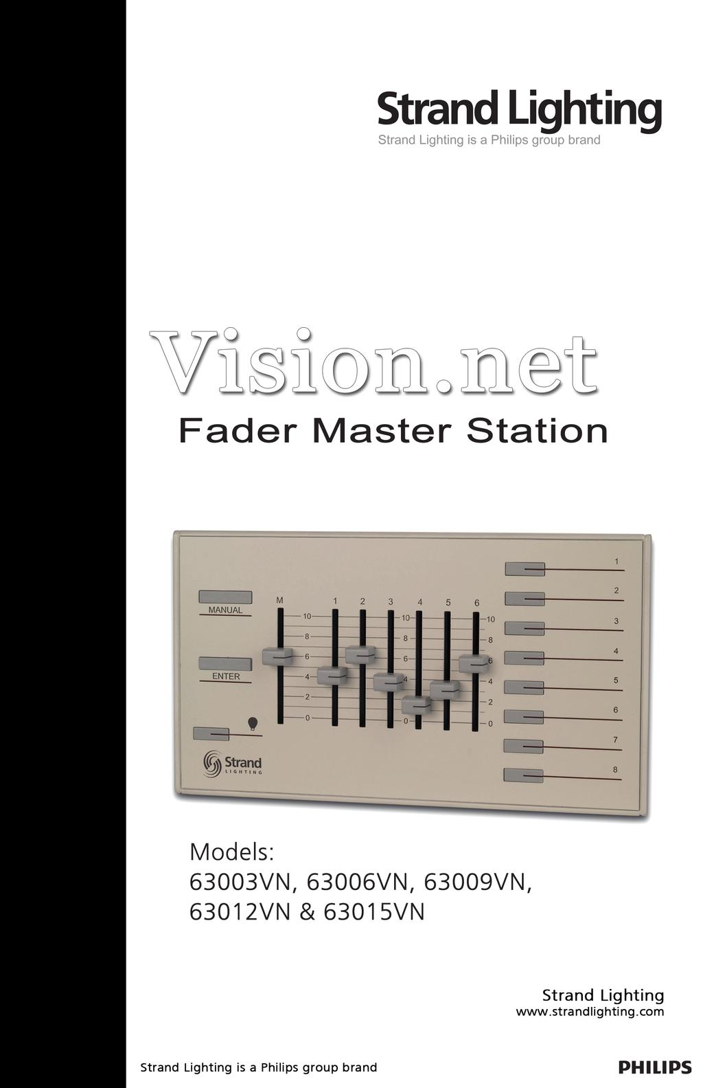
5 Fader Master Station Installation & Operation Guide Fader Master Remote Station Overview The Vision.net Fader Master Remote Stations (63003VN, 63006VN, 63009VN, 63012VN & 63015VN) are used in combination with other Vision.net Button Stations to provide quick, one-touch access to 8 Preset Scenes. The Fader panels feature a Master Fader and individual channel faders, Manual push button, Blackout push button, Enter pushbutton and eight illuminated pushbuttons which correspond to Scenes 1-8. The following diagram provides an overview of a 6 channel Fader Master Station and controls in a typical configuration. SPECIFICATIONS Electrical Input Power: VDC (powered from Vision.net network) Current: 20mA Temperature: - Storage: -25 to 85 C - Operating: 0 to 40 C - Relative Humidity: 30-90% (non-condensing) Communications Vision.net Protocol 3
6 Installation & Operation Guide Fader Master Station INSTALLATION The Vision.net Network consists of a single CAT5e cable connecting all modules in a daisy chain manner. All units connect to the network using a 9-pin plug-in connector (included). Installation Steps Step Step Step Step 1. Unpack unit and inspect for any signs of shipping damage. Ensure that two mounting screws and Allen Key are included. 2. Release the Sub Plate from the panel by loosening the set screw at the base of the panel with the supplied Allen Key. 3. Connect Sub Plate to a wall box using the two supplied mounting screws. 4. Connect Vision.net Network Cable to 9-pin connector at back of the panel Interface. Note: Use only wire specified on system drawings. All wiring must be daisy chained only. Step 5. Connect the trim panel to the sub frame and fix in place with the set screws. Note: The back box shall be inches deep, sized for the appropriate station gang width. Back box must be grounded. All Back boxes shall be provided by others. 4
7 Fader Master Station Installation & Operation Guide VISION.NET STATION OPERATION MODES Vision.net stations can be set in either Standard Mode or Configurable Mode. The default setting for the station is assigned to Room 1 in Standard Mode. A station, configured in either Standard or Configurable Mode, can be reset to the factory default as follows: Step 1. Unplug the station from the network. Step 2. Re-plug the station while pressing and holding any button for at least 3 seconds. Standard Mode In Standard Mode, you can control up to 31 rooms, each with Presets 1 to 8. Note: Standard Mode requires either 8-button stations or Slider Preset stations in each room. Assigning a station to a room: Step 1. Reset the station to the factory default, Room 1 as described above. Step 2. Press and hold Buttons 3 and 6 for 3 or more seconds to enter programming mode. When in programming mode, all button LED s are off, except for Button 1 which should be flashing. All other Stations on the network will blink with either one or two quick blinks every 2 seconds Step 3. Pressing Button 2 increases the assigned room number by 1. You can press Button 2 a maximum of 30 times assigning it up to room 31. Step 4. Stations with a single blink every 2 seconds are already set to this room. Pressing and holding any button on a blinking station that has the 2 blink pattern for 3 or more seconds, will set it to the current room. It will blink in with the single blink pattern in confirmation. Step 5. Complete the programming mode by pressing and holding Button 1 on the first station. Configurable Mode In Configurable Mode, Vision.net products are controlled by the Vision.net System protocol. All Vision.net devices must be given an ID (or address), which identifies the device on the network and allows it to avoid network collisions when transmitting data. Standard IDs are in the range of 1 to The Network ID for the panel will be pre-assigned at 1 by the factory and will need to be set to the required address and programmed as required for your installation. Vision.net stations are programmed and have their ID s set using the Vision.Net Designer software (supplied separately, part number #67518). To obtain the Vision.Net Designer software, please contact your local Strand Lighting Distributor. 5


8 Installation & Operation Guide Fader Master Station Setting the Station's Vision.net Network ID: Step 1. Connect the PC running the Vision.net Designer software to the Vision.net Network via the Vision.net RS232 station, using an RS232 lead. Alternatively you can connect to the Vision.net network using a Bluetooth interface. Please contact your local Strand Lighting Office for more details on this interface. Step 2. Set Vision.net Designer to work "On Line." Step 3. Select or add the required station from the Network Tree and press the Station ID button. Step 4. Select Set Station ID and the LED s of all unassigned stations will flash. Step 5. Press and Hold any button on the required station for 3 seconds and the station's ID will be set. Changing the Vision.net Network ID: Step 1. Connect the PC running the Vision.net Designer software to the Vision.net Network via the Vision.net RS232 station, using an RS232 lead. Alternatively you can connect to the Vision.net network using a Bluetooth interface. Please contact your local Strand Lighting Office for more details on this interface. Step 2. Set Vision.net Designer to work "On Line." Step 3. Select or add the required station from the Network Tree and press the Station ID button. Step 4. Select Change Station ID and the LED's of all stations will flash. Step 5. Press and Hold any button on the required panel for 3 seconds and that Station will be set to the current station ID. Any other station that is currently set to that ID will have its ID cleared. 6

9 Fader Master Station Installation & Operation Guide Saving the Configuration to the Station: Step 1. Connect the PC running the Vision.net Designer software to the Vision.net Network via the Vision.net RS232 station, using an RS232 lead. Alternatively you can connect to the Vision.net network using a Bluetooth interface. Please contact your local Strand Lighting Office for more details on this interface. Step 2. Set Vision.net Designer to work "On Line." Step 3. Select or add the required station from the Network Tree and set the required mode for each button as desired. Step 4. Select Upload & OK and the configuration set in the Vision.net Designers software will be saved to the station. Note: If the upload process fails, a warning will appear advising that the communications to the panel are unreliable. If this occurs, check that you have a good connection to the Vision.net network and that there is a panel with the ID that you are trying to download the information to. Refer to "Troubleshooting" on page 9. 7

10 Installation & Operation Guide Fader Master Station Downloading the current Configuration from the Station: Step 1. Connect the PC running the Vision.net Designer software to the Vision.net Network via the Vision.net RS232 station, using an RS232 lead. Alternatively you can connect to the Vision.net network using a Bluetooth interface. Please contact your local Strand Lighting Office for more details on this interface. Step 2. Set Vision.net Designer to work "On Line." Step 3. Select or add the required panel from the Network Tree and press the Get Configuration from Station button. The current configuration loaded in that panel will be downloaded to Vision.net Designer. Once the information has been downloaded the current configuration of the station will be displayed. Note: If the download process fails, a warning will appear advising that the communications to the panel are unreliable. If this occurs, check that you have a good connection to the Vision.net network and that there is a panel with the ID that you are trying to download the information to. Refer to "Troubleshooting" on page 9. 8

11 Fader Master Station Installation & Operation Guide OPERATION Selecting a Scene. Typically the 8-button on the Fader station provides access to eight Scenes (1-8). To select a Scene, press the appropriate button on the keypad. The LED will illuminate to show the selected scene. A separate button is provided for the OFF scene. Manually Setting Channel Levels. Pressing the Manual button selects the manual mode of operation, deselecting the any current scene for that room. Adjust the Master Fader and individual channel faders to give the required scene. The set levels can then be recorded into a scene on the panel. Recording a Scene. If the station does not have the "Disable Press-Hold Learn" feature enabled, pressing and holding the button on for 3 or more seconds will record the current state into the scene. The LED for the requested scene will then illuminate to confirm that it has been recorded. Note: If other actions have been programmed into the station, it is possible that LED's may not illuminate. TROUBLESHOOTING In order to determine if a Vision.net Network device is communicating, a network test signal can be sent. Standard Mode Step 1. Press and hold Buttons 3 and 6 for 3 or more seconds to enter programming mode, When in programming mode, all button LED s are off, except for Button 1 which should be flashing. Step 2. All other stations assigned to the same room will flash. Step 3. Cancel programming mode by pressing and holding Button 1 on the same station. Configurable Mode The network test signal can be sent using the Vision.net Designer software. Station Identification: Step 1. Connect the PC running the Vision.net Designer software to the Vision.net Network via the Vision.net RS232 station, using an RS232 lead. Alternatively you can connect to the Vision.net network using a Bluetooth interface. Please contact your local Strand Lighting Office for more details on this interface. Step 2. Set Vision.net Designer to work "On Line." Step 3. Select the required panel from the Network Tree and press the Station ID button. Step 4. Select Flash Station and the LED's of the selected station will flash. 9
12 Part No
KALEIDOSCOPE. Effects & Colour Control Software for GENIUS. Operator's Manual
 KALEIDOSCOPE Effects & Colour Control Software for GENIUS Operator's Manual Document No.: 85021 (A86) Issue: 2 Date: June 1994 Offices and Service Centres Asia: Canada: France: Germany: Italy: U.K: USA:
Strand Lighting Locations
 Strand Lighting Locations Philips Strand Lighting - Dallas Petal Street Dallas, TX Tel: -- Fax: -- Philips Strand Lighting - New York th Ave, th Floor New York, NY Tel: -- Fax: -- Philips Strand Lighting
Philips Strand Lighting Offices
 Philips Strand Lighting Offices Philips Strand Lighting - Dallas 10911 Petal Street Dallas, TX 75238 Tel: 214-647-7880 Fax: 214-647-8031 Philips Strand Lighting - Asia Limited Unit C, 14/F, Roxy Industrial
 QuickStart Guide Showline Offices Dallas 10911 Petal Street Dallas, TX 75238 Tel: +1 214-647-7880 Fax: +1 214-647-8030 Auckland 19-21 Kawana Street Northcote, Auckland 0627 New Zealand Tel: +64 9 481 0100
10911 Petal Street Kawana Street Dallas, TX Northcote, Auckland Fax: Tel: Fax:
 SL LEDSPOT 300 Luminaire Quickstart Guide Showline Offices Dallas Auckland 10911 Petal Street 19-21 Kawana Street Dallas, TX 75238 Northcote, Auckland 0627 Tel: +1 214-647-7880 New Zealand Fax: +1 214-647-8030
FOREWORD January
 FOREWORD 02.9692.0010 0 14 January 2011 0 PHILIPS SELECON PL1 LED LUMINAIRE SERVICE MANUAL Forward The material in this manual is for information purposes only and is subject to change without notice.
Showline Offices Dallas Petal Street Dallas, TX Tel: Fax:
 Showline Offices Dallas 10911 Petal Street Dallas, TX 75238 Tel: +1 214-647-7880 Fax: +1 214-647-8030 Asia Unit C, 14/F, Roxy Industrial Centre No. 41-49 Kwai Cheong Road Kwai Chung, N.T., Hong Kong Tel:
INSTALLATION & USER S MANUAL
 Lighting BRINGING IMAGINATION TO LIGHT INSTALLATION & USER S MANUAL 20160601 Pegasus Installation Manual Corporate Offices: 57 Alexander Street Yonkers, NY 10701 (914)-476-7987 www.altmanlighting.com The
CommuniquéPro Operator s manual
 CommuniquéPro Operator s manual Communications software For GeniusPro & Lightpalette v2.1 and later Document Number: 40/B731 Issue: 3.0 Date: 19 Jan 98 Offices And Service Centres Phone numbers do not
Lighting Control Software. Operator's Manual
 Lighting Control Software Operator's Manual Offices and Service Centres Asia: Canada: France: Germany: Italy: U.K: USA: 7th Floor Corporation Sq., 8 Lam Lok St.,Kowloon Bay, Kowloon, Hong Kong Tel: (852)
Strand Lighting Offices Philips Strand Lighting - Dallas Petal Street Dallas, TX Tel: Fax:
 Strand Lighting Offices Philips Strand Lighting - allas 10911 Petal Street allas, TX 75238 Tel: 214-647-7880 Fax: 214-647-8031 Philips Strand Lighting - sia Limited Unit, 14/F, Roxy Industrial entre No.
Commander 384. w w w. p r o l i g h t. c o. u k U S E R M A N U A L
 Commander 384 w w w. p r o l i g h t. c o. u k U S E R M A N U A L 1, Before you begin 1.1: Safety warnings...2 3 1.2: What is included...4 1.3: Unpacking instructions...4 2, Introduction 2.1: Features...4
SR - 516D DESK TOP DMX REMOTE STATION. Version: Date: 05/16/2013
 SR - 516D DESK TOP DMX REMOTE STATION Version: 1.10 Date: 05/16/2013 Page 2 of 10 TABLE OF CONTENTS DESCRIPTION 3 POWER REQUIREMENTS 3 INSTALLATION 3 CONNECTIONS 3 POWER CONNECTIONS 3 DMX CONNECTIONS 3
PRESET TEN ARCHITECTURAL TWO OWNERS MANUAL
 PRESET TEN ARCHITECTURAL TWO OWNERS MANUAL model PRE10-A2 Doug Fleenor Design 396 Corbett Canyon Road Arroyo Grande, CA 93420 (805) 481-9599 Software Version 1.0 Manual Revision 12/2/2008 Serial # 08B001
MOONRING MULTIPLES INSTALLATION INSTRUCTIONS MOONRING MULTISTAK TM STACKED CANOPY. A nd Avenue, Unit 1 Oakland,
 INSTALLATION INSTRUCTIONS MOONRING MULTIPLES MOONRING MULTISTAK TM STACKED CANOPY A 1035 22nd Avenue, Unit 1 Oakland, CA 94606 P 510.489.2530 E TalkToUs@alwusa.com W alwusa.com MR-MultiStak - Safety &
DUAL/QUAD DISPLAY CONTROLLER Operation Manual
 DUAL/QUAD DISPLAY CONTROLLER Operation Manual Model PXD524 MicroImage Video Systems division of World Video Sales Co., Inc PO Box 331 Boyertown, PA 19512 Phone 610-754-6800 Fax 610-754-9766 sales@mivs.com
Installation Guide. CTI/1 RS422/BBV Coax Telemetry Interface Single Channel
 CTI/1 RS422/BBV Coax Telemetry Interface Single Channel Installation Guide Building Block Video Ltd 17 Apex Park, Diplocks Industrial Estate, Hailsham, East Sussex, BN27 3JU, UK Tel: + 44 (0) 1323 842727
Aspect 2 Circuit Digital Scene Control
 Aspect 2 Circuit Digital Scene Control S p e c i f i c a t i o n 2 circuits of trailing edge dimming 500W total between the two circuits Both circuits feature independent overload, short-circuit and open-circuit
USER MANUAL. Kramer Electronics, Ltd. Models:
 Kramer Electronics, Ltd. USER MANUAL Models: VS-88A, 8 x 8 Balanced Audio Matrix Switcher VS-88V, 8 x 8 Video Matrix Switcher SD-7588V, 8 x 8 SDI Matrix Switcher Contents Contents 1 Introduction 1 2 Getting
USER MANUAL. DV-HSW-41 HDMI 4x1 SWITCHER LIT Bergen Boulevard, Woodland Park, NJ Tel FAX Web
 USER MANUAL DV-HSW-41 HDMI 4x1 SWITCHER 244 Bergen Boulevard, Woodland Park, NJ 07424 Tel 973-785-4347 FAX 973-785-3318 Web www.fsrinc.com LIT1372 PROPRIETARY INFORMATION All information in this manual
NT-9600 Wireless Barcode Scanner. Introduction
 Guangzhou Netum Electronic Technology Co., Ltd TEL: +86 20 82679969*816 FAX: +86 20 82684887 E-mail: scottchiu@gzxlscan.com Address: Unit137, the Pacific Industry Area, Xintang Town, Zengcheng District,
192 Channel DMX Controller
 DM-X 92 Channel DMX Controller USER MANUAL 54. 9UK Vers ion. D M X 5 2 C O N T R O L L E R S E R I E S Content. Before you begin. What is included.......2 Unpacking instructions....3 Safety instructions...
MANUAL ENGLISH Core Club Ordercode: D2314
 MANUAL ENGLISH Core Club Ordercode: Highlite International B.V. Vestastraat 2 6468 EX Kerkrade the Netherlands Table of contents Warning... 2 Unpacking Instructions... 2 Safety Instructions... 2 Operating
Model 5250 Five Channel Digital to Analog Video Converter Data Pack
 Model 5250 Five Channel Digital to Analog Video Converter Data Pack E NSEMBLE D E S I G N S Revision 3.1 SW v2.0.1 This data pack provides detailed installation, configuration and operation information
OPERATING MANUAL. DMX / DSI / DALI Dekoder 3004B-H Mk2
 OPERATING MANUAL DMX / DSI / DALI Dekoder 3004B-H Mk2 (C) SOUNDLIGHT 1996-2004 * ALL RIGHTS RESERVED * NO PART OF THIS MANUAL MAY BE REPRODUCED, DUPLICATED OR USED COMMERCIALLY WITHOUT THE PRIOR WRITTEN
Connevans.info. DeafEquipment.co.uk. This product may be purchased from Connevans Limited secure online store at
 Connevans.info Solutions to improve the quality of life Offering you choice Helping you choose This product may be purchased from Connevans Limited secure online store at www.deafequipment.co.uk DeafEquipment.co.uk
Yoke Safety cable loop. Up Light Bulb
 Source Four LED Profile Overview For complete information and step-by-step instructions, see the User Manual. ETC documentation can be downloaded at www.etcconnect.com. Yoke Safety cable loop Yoke locking
MS2540 Current Loop Receiver with RS485 Communication
 MS2540 Current Loop Receiver with RS485 Communication User Manual Metal Samples Company A Division of Alabama Specialty Products, Inc. 152 Metal Samples Rd., Munford, AL 36268 Phone: (256) 358 4202 Fax:
TRANSCENSION 6-CHANNEL DMX DIMMER PACK (order code: BOTE40) USER MANUAL
 USER MANUAL") www.prolight.co.uk TRANSCENSION 6-CHANNEL PACK (order code: BOTE40) USER MANUAL SAFETY WARNING FOR YOUR OWN SAFETY, PLEASE READ THIS USER MANUAL CAREFULLY BEFORE YOUR INITIAL START-UP! CAUTION! Keep this
www.prolight.co.uk TRANSCENSION 6-CHANNEL PACK (order code: BOTE40) USER MANUAL SAFETY WARNING FOR YOUR OWN SAFETY, PLEASE READ THIS USER MANUAL CAREFULLY BEFORE YOUR INITIAL START-UP! CAUTION! Keep this
I N S T R U C T I O N D A T A
 I N S T R U C T I O N D A T A RFL (C37.94) Fiber Service Unit Single Mode 108015-1 RS-449 108015-2 V.35 108015-3 G.703 108015-4 X.21 108015-5 E1 Multimode 107460-1 RS-449 107460-2 V.35 107460-3 G.703 107460-4
RERUN ARCHITECTURAL DMX512 RECORDER OWNERS MANUAL
 RERUN ARCHITECTURAL DMX512 RECORDER MODEL RERUN-A OWNERS MANUAL Doug Fleenor Design 396 Corbett Canyon Road Arroyo Grande, CA 93420 (805) 481-9599 Software Version 1.0 Manual Revision 0 Serial #069177
P-2 Installing the monitor (continued) Carry out as necessary
 Carry out as necessary") P-2 Installing the monitor (continued) Carry out as necessary Using the monitor without the bezel MDT552S satisfies the UL requirements as long as it is used with the bezel attached. When using the monitor
P-2 Installing the monitor (continued) Carry out as necessary Using the monitor without the bezel MDT552S satisfies the UL requirements as long as it is used with the bezel attached. When using the monitor
Kramer Electronics, Ltd. USER MANUAL. Model: VS x 1 Sequential Video Audio Switcher
 Kramer Electronics, Ltd. USER MANUAL Model: VS-120 20 x 1 Sequential Video Audio Switcher Contents Contents 1 Introduction 1 2 Getting Started 1 2.1 Quick Start 2 3 Overview 3 4 Installing the VS-120 in
Trusted 40 Channel Analogue Input FTA
 PD-T8830 Trusted Trusted 40 Channel Analogue Input FTA Product Overview The Trusted 40 Channel Analogue Input Field Termination Assembly (FTA) T8830 is designed to act as the main interface between a field
Application Note #428 Revision A April 2012 Wired seetouchr QS Wallstation: Advanced Programming Mode
 Revision A April 2012 Wired seetouchr QS Wallstation: Advanced Programming Mode Wired seetouchr QS Wallstations contain an Advanced Programming Mode (APM) that allows installers to customize wallstations
Power Injector 1520 Series
 Power Injector 1520 Series Technical Specifications Input voltage 100 to 240 VAC Output voltage 56.0 VDC Voltage range tolerance 54 VDC to 57 VDC Maximum current 1.43 A No load current 15 ma 56VDC@0.71A
Installation and User Guide 458/CTR8 8-Channel Ballast Controller Module
 Installation and User Guide 458/CTR8 8-Channel Ballast Controller Module Helvar Data is subject to change without notice. www.helvar.com i Contents Section Page Introduction 1 Installation 2 1. Attach
FB10000 Error Messages Troubleshooting
 FB10000 Error Messages FB10000 Error Messages Error ID: 67009: Safety - Bridge front door is open. Error Severity: Critical Possible Causes The bridge front door is open The bridge front door interlock
Manual Addendum For Rerun V1.1 software 12/12/2006, RERUN-A = Serial #06A068, RERUN-P = Serial #06A031
 Manual Addendum For Rerun V1.1 software 12/12/2006, RERUN-A = Serial #06A068, RERUN-P = Serial #06A031 The Rerun product manual was written for V1.0 software. The new release, V1.1, adds a number of new
iw Scene Controller Control intelligent white light fixtures at the touch of a button
 Control intelligent white light fixtures at the touch of a button Control intelligent white light fixtures at the touch of a button gives you instantaneous, pushbutton control of the entire range of Philips
SceneStyle2 User Guide
 SceneStyle2 User Guide Mode Lighting (UK) Limited. The Maltings, 63 High Street, Ware, Hertfordshire, SG12 9AD, UNITED KINGDOM. Telephone: +44 (0) 1920 462121 Facsimile: +44 (0) 1920 466881 e-mail: website:
ETC Quick Guide. Source Four LED Profile
 ETC Quick Guide Source Four LED Profile Overview For complete information and step-by-step instructions, see the Source Four LED Profile User Manual. ETC documentation can be downloaded at www.etcconnect.com.
Installation Guide. HDMI 4x1 Switcher
 Installation Guide HDMI 4x1 Switcher SY Electronics Ltd, Unit 7, Worrall Street, Salford, Greater Manchester, M5 4TH, United Kingdom Tel: +44 (0) 161 868 3450 Fax: +44 (0) 161 868 3459 The SY-HD-S41 is
USER INSTRUCTIONS MODEL CSI-200 COAXIAL SYSTEM INTERFACE
 USER INSTRUCTIONS MODEL CSI-200 COAXIAL SYSTEM INTERFACE 9350-7676-000 Rev B, 5/2001 PROPRIETARY NOTICE The RTS product information and design disclosed herein were originated by and are the property of
The features shown in the following graphics may not appear on all Desire Series fixtures. LCD Power In DMX In
 Desire Fixture Series Overview For complete information and step-by-step instructions, see Desire Series by ETC D22, D40, D40XT, D60, D60X User Manual. ETC documentation can be downloaded at www.etcconnect.com/downloads.aspx.
STAGE SETTER-8. User Instructions. Elation Professional 4295 Charter Street Los Angeles Ca
 Introduction STAGE SETTER-8 User Instructions Introduction: Thank you for purchasing the Elation Professional Stage Setter 8. To optimize the performance of this product, please read these operating instructions
INSTALLATION & USER GUIDE
 INSTALLATION & USER GUIDE Digidim 458 8-Channel Dimmer STEP 1 Assemble Dimmer Unit STEP 2 Mount Dimmer Chassis STEP 3 Electrical Installation STEP 4 Attach Module and Make Connections STEP 5 Replace Cover
Digital Lighting Systems, Inc.
 , Inc. Series DMX CHASER/CROSS-FADER Controllers MODE RUN RATE MAX. MIN. Lighting Animation Controller FADE AUTO STOP BLK. OUT DIM1 DIM2 DIM3 DIM4 MODEL NUMBERS 2 2C Miami, Fl. USA digitallighting.com
RA-RS232, RB-RS232. Setup and Installation Guide Addendum For RadioRA RS232 Interface
 RA-RS232, RB-RS232 Setup and Installation Guide Addendum For RadioRA RS232 Interface A Comprehensive Step-by-Step Guide for Programming and Operating the Lutron RadioRA RS232 Interface Note: Please leave
OWNERS MANUAL. Revision /29/ Lightronics Inc. 509 Central Drive Virginia Beach, VA Tel
 OWNERS MANUAL Revision 1.87 01/29/2006 Page 2 of 17 TABLE OF CONTENTS AR-1202 UNIT DESCRIPTION 3 EXTERNAL CONTROLS 3 POWER REQUIREMENTS 3 INSTALLATION 3 Physical Location 3 Power Input Connections 3 Three
USER GUIDE. DM Engineering Multi Station Relay Adapter (MSRA and MSRA-RM) Version DM Engineering
 Version DM Engineering") USER GUIDE DM Engineering Multi Station Relay Adapter (MSRA and MSRA-RM) Version 1.35 DM Engineering 2174 Chandler St. Camarillo, CA 91345-4611 805-987-7881 800-249-0487 www.dmengineering.com Overview:
USER GUIDE DM Engineering Multi Station Relay Adapter (MSRA and MSRA-RM) Version 1.35 DM Engineering 2174 Chandler St. Camarillo, CA 91345-4611 805-987-7881 800-249-0487 www.dmengineering.com Overview:
User Guide. Centrex Recording Interface
 User Guide Centrex Recording Interface Table of Contents Introduction... 2 The Meridian Business Set... 3 Key Numbering Plan (18 button add-on)... 4 Key Numbering Plan (36 button add-on)... 5 Key Numbering
-TECH DIGITAL. Explore The High DefinitionWorld. Website: Hot Line: [US] USER MANUAL
![-TECH DIGITAL. Explore The High DefinitionWorld. Website: Hot Line: [US] USER MANUAL](/thumbs/80/80689593.jpg "-TECH DIGITAL. Explore The High DefinitionWorld. Website: Hot Line: [US] USER MANUAL") -TECH DIGITAL Explore The High DefinitionWorld Website: www.jtechdigital.com Hot Line: 1-888-610-2818[US] USER MANUAL J-Tech Digital ProAV H.264 Encoder/Decoder Many to Many HDMI Extender RoHS 1 Operating
-TECH DIGITAL Explore The High DefinitionWorld Website: www.jtechdigital.com Hot Line: 1-888-610-2818[US] USER MANUAL J-Tech Digital ProAV H.264 Encoder/Decoder Many to Many HDMI Extender RoHS 1 Operating
Artistic Licence. moody & moody cv. User Guide. Download the user guide by scanning the following QR code: moody & moody cv User Guide.
 Artistic Licence moody & moody cv User Guide Download the user guide by scanning the following QR code: moody & moody cv User Guide Version 2-0 Please read these instructions before using the product.
Snapshot. Obey 10 DMX Controller USER MANUAL
 Obey 10 DMX Controller Snapshot Ok on Dimmer Outdoor OK Sound Activated DMX512 Master/Slave 115V/230V Switch Replaceable Fuse User Serviceable Duty Cycle USER MANUAL Chauvet, 3000 N 29 th Ct, Hollywood,
RD RACK MOUNT DIMMER OWNERS MANUAL VERSION /09/2011
 RD - 122 RACK MOUNT DIMMER OWNERS MANUAL VERSION 1.3 03/09/2011 Page 2 of 14 TABLE OF CONTENTS UNIT DESCRIPTION AND FUNCTIONS 3 POWER REQUIREMENTS 3 INSTALLATION 3 PLACEMENT 3 POWER CONNECTIONS 3 OUTPUT
Scoreboard Operator s Instructions MPCX SCD / DGT / Pitch Time Control
 Scoreboard Operator s Instructions MPCX SCD / DGT / Pitch Time Control Since 1934 Retain this manual in your permanent files Rev. 2/3/2012 135-0136 These Instructions are for the Following Models: LED
Trusted 40 Channel 120 Vac Digital Input FTA
 PD-T8824 Trusted Trusted 40 Channel 120 Vac Digital Input FTA Product Overview The Trusted 40 Channel 120 Vac Digital Input Field Termination Assembly (FTA) T8824 is designed to act as the main interface
Junior Max (JR Max ) Controller
 Controller") Get more done TM Junior Max (JR Max ) Controller stations Operating Instructions Thank you for purchasing this advanced, highly featured Irritrol Junior MAX controller. The Junior MAX is the latest addition
Get more done TM Junior Max (JR Max ) Controller stations Operating Instructions Thank you for purchasing this advanced, highly featured Irritrol Junior MAX controller. The Junior MAX is the latest addition
Operating Instructions
 Marshall Electronics Broadcast A/V Division Model No. VSW-2200 4-Input Seamless SDI A/V Switcher Operating Instructions Table of Contents 1. Overview... 2. Features.... Package Contents... 4. Specifications...
Dragonfly Quad. User Manual V1.4. Order code: EQLED101
 Dragonfly Quad User Manual V1.4 Order code: EQLED101 Safety advice WARNING FOR YOUR OWN SAFETY, PLEASE READ THIS USER MANUAL CAREFULLY BEFORE YOUR INITIAL START-UP! Before your initial start-up, please
Trusted 40 Channel 120 Vac Digital Input FTA
 ICSTT-RM290F-EN-P (PD-T8824) Trusted Product Overview The Trusted 40 Channel 120 Vac Digital Input Field Termination Assembly (FTA) T8824 is designed to act as the main interface between a field device
Model: UHD41-ARC. Installation Guide
 Model: UHD41-ARC Installation Guide 1 Safety Information: Electrical safety Use only the power supplies and the AC power cord that were included with your product. Use of other power supplies could damage
DMX48. User s instruction manual. 24 Channel DMX controller
 WWW.LIGHTEMOTIONS.COM.AU DMX48 24 Channel DMX controller User s instruction manual This manual contains important information about the safe installation and use of this product Please read this instruction
TeamWork 601 Kit Installation Guide
 C G G TX RX COM +V APARATUS US 0 TeamWork 0 Kit Installation Guide TeamWork 0 Kit The TeamWork 0 kit consists of an analog and digital video switcher, system controller, Cable Cubby, and cables packaged
TL5024 MEMORY LIGHTING CONSOLE OWNERS MANUAL. Version 1.01
 TL5024 MEMORY LIGHTING CONSOLE OWNERS MANUAL Version 1.01 09/22/2017 Page 2 of 14 SPECIFICATIONS Total channels Operating modes Scene memory Chase 12 or 24 depending on mode 12 channels x 2 manual scenes
Inspire Station. Programming Guide. Software Version 3.0. Rev A
 Inspire Station Programming Guide Software Version 3.0 Rev A Copyright 2016 Electronic Theatre Controls, Inc. All rights reserved. Product information and specifications subject to change. Part Number:
TeamWork Kits Installation Guide
 TX 0 RX COM +5V APARATUS US TeamWork Kits Installation Guide TeamWork 400 and TeamWork 600 Kits The TeamWork 400 and TeamWork 600 kits consist of an HDMI switcher, system controller, Cable Cubby, and cables
Smart Control SC16 3-Channel for matrix
 Operating Manual Smart Control SC16 3-Channel for matrix Dear Customer, Thank you for choosing a WALTRON daytime lighting controller. Your daytime lighting controller is a high-quality product that was
For warranty service, please contact Microframe at: A technician will gladly assist you.
 Your Microframe System is warranted against failure due to defects in workmanship or material for a period of one (1) year from the date of purchase. Microframe Corporation will repair or replace any defective
GAUGEMASTER PRODIGY EXPRESS
 GAUGEMASTER PRODIGY EXPRESS DCC01 USER MANUAL Version 1.2 2014 1 T A B L E O F C O N T E N T S 1 Getting Started Introduction Specifications and Features Quick Start Connecting to Your Layout Running a
CH-2538TXWPKD 4K UHD HDMI/VGA over HDBaseT Wallplate Transmitter. CH-2527RX 4K UHD HDMI over HDBaseT Receiver. Operation Manual
 CH-2538TXWPKD 4K UHD HDMI/VGA over HDBaseT Wallplate Transmitter CH-2527RX 4K UHD HDMI over HDBaseT Receiver Operation Manual DISCLAIMERS The information in this manual has been carefully checked and
VNS2200 Amplifier & Controller Installation Guide
 VNS2200 Amplifier & Controller Installation Guide VNS2200 Amplifier & Controller Installation 1. Determine the installation location for the VNS2200 device. Consider the following when determining the
Contents: 1 LANsmart Pro Main Unit 4 Remote Unit: ID1, ID2, ID3, ID4
 LANsmart Pro user manual Introduction LANsmart Pro is a hand-held, multifunction Cable Map Tester and Cable Length Meter. It has an integrated Analog and Digital Tone Generator, Port Finder, and Quick
Operation/Reference Guide IRIS. Infrared/Serial Data Capture Unit. Control System Accessories
 Operation/Reference Guide IRIS Infrared/Serial Data Capture Unit Control System Accessories Last Revised: 1/17/2007 AMX Limited Warranty and Disclaimer All products returned to AMX require a Return Material
Telemetry Receiver Installation Guide
 BBV Telemetry Receiver Installation Guide Models covered Rx200 Building Block Video Ltd., Unit 1, Avocet Way, Diplocks Industrial Estate, Hailsham, East Sussex, UK. Tel: +44 (0)1323 842727 Fax: +44 (0)1323
USER MANUAL. 27 Full HD Widescreen LED Monitor L27ADS
 USER MANUAL 27 Full HD Widescreen LED Monitor L27ADS TABLE OF CONTENTS 1 Getting Started 2 Control Panel/ Back Panel 3 On Screen Display 4 Technical Specs 5 Care & Maintenance 6 Troubleshooting 7 Safety
Scoreboard Operator s Instructions MPCX Volleyball Control
 Scoreboard Operator s Instructions MPCX Volleyball Control Since 1934 Retain this manual in your permanent files Rev. 2/3/2012 135-0137 These Instructions are for the Following Models: LED models: Incandescent
GE Interlogix Fiber Options S700VT-MST. Instruction Manual FIBER-OPTIC MINIATURE VIDEO TRANSMITTER
 g GE Interlogix Fiber Options Instruction Manual S700VT-MST FIBER-OPTIC MINIATURE VIDEO TRANSMITTER Federal Communications Commission and Industry Canada Radio Frequency Interference Statements This equipment
Single cable multiswich programmer PC102W
 Single cable multiswich programmer PC102W 1. Product description The PC102W - single cable multiswich programmer (in the text - programmer) is useful instrument while configuring and troubleshooting SAT
GE Interlogix Fiber Options S700V & S702V. Instruction Manual FIBER-OPTIC VIDEO TRANSMISSION SYSTEM
 g GE Interlogix Fiber Options Instruction Manual S700V & S702V FIBER-OPTIC VIDEO TRANSMISSION SYSTEM Federal Communications Commission and Industry Canada Radio Frequency Interference Statements This equipment
INSTALLATION INSTRUCTIONS MODEL VSBX-236 LED 3 X 8 INDOOR SCOREBOARD
 1 INSTALLATION INSTRUCTIONS MODEL VSBX-236 LED 3 X 8 INDOOR SCOREBOARD NOTE TO INSTALLERS: PLEASE RETURN THIS MANUAL TO THE INDIVIDUAL IN CHARGE OF THE SCOREBOARD UPON COMPLETION OF INSTALLATION. The scoreboard
FB10000 Error Messages Troubleshooting
 Error ID: 67019: Safety - Front manual loading flap is down Error Severity: Critical Possible Causes Front manual loading flap is down Interlocks connecting flap are misaligned Interlock is faulty or cable
DA IN 1-OUT LINE DRIVER WITH EQUALIZATION + AUDIO USER S GUIDE
 MANUAL PART NUMBER: 400-0430-001 1-IN 1-OUT LINE DRIVER WITH UALIZATION + AUDIO USER S GUIDE TABLE OF CONTENTS Page PRECAUTIONS / SAFETY WARNINGS... 2 GENERAL...2 GUIDELINES FOR RACK-MOUNTING...2 INSTALLATION...2
Package Contents. LED Protocols Supported. Safety Information. Physical Dimensions
 Pixel Triton Table of Contents Package Contents... 1 Safety Information... 1 LED Protocols Supported... 1 Physical Dimensions... 1 Software Features... 2 LED Status... 2 Power... 2 Activity LED... 2 Link
USER MANUAL. 27" 2K QHD LED Monitor L27HAS2K
 USER MANUAL 27" 2K QHD LED Monitor L27HAS2K TABLE OF CONTENTS 1 Getting Started 2 Control Panel/ Back Panel 3 On Screen Display 4 Technical Specs 5 Troubleshooting 6 Safety Info & FCC warning 1 GETTING
OPERATOR MANUAL Version 2.3 May 2007
 OPERATOR MANUAL Version 2.3 May 2007 Supplied by: LSC Lighting Systems (Aust) Pty Ltd ABN 21 090 801 675 7 University Place, Clayton Victoria, 3168 Australia Tel: +61 3 9561 5255 Fax: +61 3 9561 5277 Email:
4 Wiring Brochure Wiring and installation of specific control
 - Wiring Brochure tekmarnet 4 User Switch 480 W 480 09/09 1 Information Brochure Choose controls to match application 2 Application Brochure Design your mechanical applications 3 Rough In Wiring Rough-in
Color mixing or White-light LED (Light Emitting Diode) ERS-style product
 ERS-style product") WHT Color mixing or White-light LED (Light Emitting Diode) ERS-style product GENERAL PHYSICAL A. The product shall be an Ovation E-910FC as manufactured by Chauvet & Sons, LLC or approved equal. 1. The
WHT Color mixing or White-light LED (Light Emitting Diode) ERS-style product GENERAL PHYSICAL A. The product shall be an Ovation E-910FC as manufactured by Chauvet & Sons, LLC or approved equal. 1. The
USER MANUAL DUX-TX DUX-RX HDMI EXTENDER
 USER MANUAL DUX-TX DUX-RX HDMI EXTENDER Table of Contents Important Safety Instructions...03 Introduction...04 Features...04 Packing List...05 Specifications...06 DUX-TX Transmitter...06 DUX-RX Receiver...07
OWNERS MANUAL. Revision /01/ Lightronics Inc. 509 Central Drive Virginia Beach, VA Tel
 OWNERS MANUAL Revision 1.8 09/01/2002 OWNERS MANUAL Page 2 of 12 AR-1202 UNIT DESCRIPTION The AR-1202 consists of a processor and 12 dimmer channels of 2.4KW each. Each dimmer channel is protected by a
Kramer Electronics, Ltd. USER MANUAL. Model: 900xl. Power Amplifier
 Kramer Electronics, Ltd. USER MANUAL Model: 900xl Power Amplifier Introduction Contents 1 Introduction 1 2 Getting Started 1 2.1 Recycling Kramer Products 1 3 Overview 2 4 Your 900xl Power Amplifier 3
7 Day Digital Programmer 3 Channel Surface Mount
 7 Day Digital Programmer 3 Channel Surface Mount Model: TRT038N Installation & Operating Instructions 1. General Information These instructions should be read carefully and retained for further reference
INSTALLATION INSTRUCTIONS FOR. MODEL 2230LED
 INSTALLATION INSTRUCTIONS FOR MODEL 2230LED www.sportablescoreboards.com 1 Table of Contents MODEL 2230LED... 3 8 X 4 INDOOR SCOREBOARD... 3 THE SCOREBOARD SYSTEM SHOULD INCLUDE THE FOLLOWING PARTS:...
Preset 10 Ethernet Interface Configuration & Owner s Manual
 Preset 10 Ethernet Interface Configuration & Owner s Manual model: PRE10E-A Doug Fleenor Design, Inc. 396 Corbett Canyon Road Arroyo Grande, CA 93420 (805) 481-9599 Voice and FAX Manual Revision 0 September
INSTALLATION INSTRUCTIONS FOR
 INSTALLATION INSTRUCTIONS FOR MODEL 2240LED www.sportablescoreboards.com 1 Table of Contents 8 X 7 INDOOR SCOREBOARD... 3 THE SCOREBOARD SYSTEM SHOULD INCLUDE THE FOLLOWING PARTS:... 3 INSTRUCTIONS FOR
ACCESSORIES MANUAL PART NUMBER: TNP500. Universal Tilt N Plug Interconnect Box USER'S GUIDE
 MANUAL PART NUMBER: 400-0091-003 TNP500 Universal Tilt N Plug Interconnect Box USER'S GUIDE INTRODUCTION Your purchase of the TNP100 Tilt N Plug Interconnect Box is greatly appreciated. We are sure you
EDITION NOTES. Document Revision
 User Manual EDITION NOTES The VIP Drive 43Nova User Manual includes a description, safety precautions, installation, programming, operation, and maintenance instructions for the VIP Drive 43Nova as of
APOLLO DESIGN TECHNOLOGY 4130 Fourier Drive Fort Wayne, IN USA Phone: Fax:
 APOLLO DESIGN TECHNOLOGY 4130 Fourier Drive Fort Wayne, IN 46818 USA Phone: +01.260.497.9191 Fax: +01.260.497.9192 www.apollodesign.net 07.26.10 Operating Manual [ Table of Contents ] Safety Information.
Video wall Precautions when moving and handling. Precaution. Please adhere to the warning signs printed on the box.
 Video wall Precaution 4-1. Precautions when moving and handling Please adhere to the warning signs printed on the box. Model: 47WV30MS 47WV30BR 47WV30BS 47WV30-BAAM 47WV30-BAAL 47WV50BR 47WV50MS 47LV35A