Light Generation & Control Beam Splitters/Combiners Beam Modifiers Rotary Joints Patch Cords Cannulas In vitro and In vivo
|
|
|
- Morris Hawkins
- 5 years ago
- Views:
Transcription

1
2
3 Contents Light Generation & Control 11 LED Illumination Laser Diode Illumination Ce:YAG Fluorescent Illumination Modulators Beam Splitters/Combiners 31 Doric Mini Cubes Doric Micro Splitters Doric Multiple Splitters/Combiners Beam Modifiers 37 Filtering NA Converter Rotary Joints 39 Fiber-optic Rotary Joints Electrical Rotary Joints Fiber-optic & Electric Rotary Joints Fiber-optic & Liquid Rotary Joints Patch Cords 56 Fiber-optic Patch Cords Electrical Patch Cords Opto-electric Patch Cords Cannulas 71 Fiber-optic Cannulas Opto-electric Cannulas Opto-fluid Cannulas Stereotaxic Tools In vitro and In vivo (head-fixed animal) Illumination 100 Optical Fiber Probes Opto-electric Probes Single-cell Recording Opto-electric Probe Single-cell Recording Opto-electric Probe Systems Miniaturized Fluorescence Microscopy 112 Miniaturized Fluorescence Microscopy Systems Fluorescence Microscope Bodies Snap-in Imaging Cannulas Fluorescence Microscope Drivers Fluorescence Microscope Accessories Fiber Photometry 142 Fiber Photometry Systems
4 Fiber Photometry Console Connectorized Fluorescence Mini Cubes Photodetectors Fiber Photometry Cannula Holders Behavioral Tracking 158 Behavior Tracking Cameras Optogenetically Synchronized Electrophysiology (OSE) 163 Optogenetically Synchronized Electrophysiology Systems Optogenetically Synchronized Electrophysiology Components Doric Neuroscience Studio 169 Software Modules Accessories 170
5 Overview of Neuro-photonics products catalog Over the years, this catalog has overgrown its optogenetics roots to become a reference of neurophotonics products. Initially, it covered only the hardware that was used for light stimulation and/or control of cells marked with genetically encoded light-sensitive proteins. In these experiments, the light from a laser or a LED source is sent over an optical fiber to the slice of brain tissue or to the brain of a head-fixed or freely-moving animal. Overtime, this simple optical link has evolved into a more complex circuitry, resembling the early days fiber-optic telecommunication network. This fiber-to-the-brain (FTTB) network consists of fiber coupled light sources and their drivers, light shutters or modulators, rotary joints for experiments with freely-moving animals, beam-splitters, fiberoptic patch cords, various fiber-optic cannulas and much more. In addition to delivering light pulses to the tissue, this network monitors the interaction of tissue with light, sends and records electrical signals and administers different fluids. While optogenetics is more about controlling the brain by putting some parts on or off, there is a need for monitoring changes in the brain cells activity. Perfect tools for that seem to be fiber photometry and head-on miniature fluorescent microscopy and we have dedicated a significant part of the catalog to address related hardware issues. The following pages show some examples of possible FTTB optogenetics and fiber photometry configurations. 5
 Bilateral optogenetic stimulation with a Connectorized LED with Fiber-optic")
6 (Left) Optogenetic stimulation with a Laser Diode Fiber Light Source. (Right) Bilateral optogenetic stimulation with a Connectorized LED with Fiber-optic Rotary Joint.
7 (Left) Dual optogenetic stimulation with a Laser Diode Fiber Light Source. (Right) 2-color optogenetic stimulation with a Ce:YAG + LED Fiber Light Source.
8 (Left) Fiber Photometry System with a Connectorized Fluorescence Mini Cube 5 ports and the Fiber Photometry Console. (Right) Miniaturized Fluorescence Microscopy System used for calcium imaging with GCaMP6.

9 (Left) Optogenetic stimulation and electrophysiology recordings with an Opto-electric Probe Tip. (Right) Optogenetic stimulation and fluid delivery with a Mono Opto-fluid Cannula.
10 Fiberless & Wireless Optogenetically Synchronized Electrophysiology System and Behavior Tracking Camera

11 Light Generation & Control LED Illumination Light emitting diodes (LEDs) coupled in an optical fiber are suitable for neuroscience experiments which need to bring the light into the brain. LED light allows to control the excitation, inhibition or signalling of specific cells in optogenetic experiments. The uniform illumination of an LED makes it the first choice in light sources for fluorescence miniature microscopy and fiber photometry techniques. Our compact Connectorized LEDs or multiple color combined LEDs are used with Doric programmable LED Drivers. We also offer LED Fiber Light Sources integrating 1, 2, or 4 independently controlled LEDs into the driver housing. LED Modules Connectorized LEDs Doric Connectorized LEDs couple high brightness LEDs into an FC receptacle compatible with an FC connectorized fiberoptic patch cord. Each Connectorized LED is actively aligned for optimum output power and its optical design provides the maximum fiber-coupling efficiency into multimode optical fibers. Connectorized LED Each Connectorized LED includes an EPROM memory enabling its identification by the driver. The wavelength is recognized and the maximum current is automatically set to avoid accidental overdrive. Doric Connectorized LEDs are easily screwed on an optical table for a basic passive cooling suitable for low power and pulsed operations. During high power cw applications, an active cooling is obtained by connecting the internal fan with a micro-usb power supply. This is essential to maximize the device life span and obtain stable performances in terms of output power. Notes: A micro-usb power supply is included with each Connectorized LED. A Connectorized LED does not include the corresponding LED Driver. See Table 4 for available LED Driver models. An Optical Breadboard for Connectorized LED (LEDB; see Table 95) is available to mount systems including two Connectorized LEDs. 11
12 12 Light Generation & Control Table 1: Typical Connectorized LED Output Power vs Optical Fiber Core Diameter LED Central Wavelength (nm) Bandwidth FWHM (nm) Core 200 µm 0.53 NA TYPICAL OUTPUT ma (mw) ma (pulsed) Core 400 µm 0.53 NA Core 960 µm 0.63 NA x x x x x x x K The power is given for Connectorized LEDs and LEDs with Fiber-optic Rotary Joints (LEDFRJ). Contact us for power levels for other LED products. Connectorized LED male pinout All power values taken at a maximum current of 1000 ma, except for 365, 385, 405 and 420 nm LEDs (500 ma). In overdrive mode, LED drivers can produce current pulses of up to 2000 ma.

13 Light Generation & Control 13 Color ORDERING CODE: CLED LED color code (see Table 2) Table 2: Connectorized LEDs Color Codes Central Wavelength (nm) LED Color Code Near UV Near UV Near UV Violet Royal Blue Cyan Green Lime Amber Orange Red Infrared Infrared White 5500K W55 LED Drivers Doric programmable LED Drivers are available in 1-, 2-, and 4-channel versions. When connected to a Connectorized LED having an eprom memory, the LED Driver recognizes the LED wavelength and automatically sets the maximum current value to avoid accidental overdriving. Two-channel LED Driver In stand-alone mode, all LED Drivers allow cw operation and external analog modulation through an input BNC connector for each channel. For each channel, there is also a current monitoring BNC output allowing data acquisition or triggering of other devices. When using Doric Neuroscience Studio Software, more advanced operating modes are available such as TTL modulation and software
14 14 Light Generation & Control defined illumination sequences, thus eliminating the need for a function generator. In low-duty cycle pulsed mode, the software allows to overdrive the LED sources if a higher power is needed. For multiple channel driver versions, each channel is controlled independently. Although not mandatory for LED sources, our LED Drivers come with a safety interlock connector and a main key switch. These safety features are of interest for UV and near infrared LEDs. Note: The renewed line of Doric LED Drivers has a new connector pinout that does not include pins for fan power. It is thus essential to use a Fan Power Adapter (FPA; see Table 94) when using Combined LEDs or Combined LEDs with a Fiber-optic Rotary Joint. This power adapter is suitable for up to 4 channels and is sold with corresponding M8 cables. Table 3: LED Drivers Specifications SPECIFICATION Maximum current Input BNC modulation Output BNC monitoring Output LED connector VALUE 1 A (2 A overdrive) 0-5 V TTL or analog (400 ma/v) 0-5 V (2.5 V/A) M8 4-pin female LED Driver female pinout Table 4: LED Drivers Ordering Codes Number of Channels Ordering Code 1 LEDD 1 2 LEDD 2 4 LEDD 4 8 LEDD 8 8-channel LED Driver is available on request


15 Light Generation & Control 15 Combined LEDs Doric Combined LEDs merge the light from multiple LEDs of different colors into a single output connector by using a patent pending regular pentagon mirrors configuration. The coupling efficiency for respective colors is near those of our Connectorized LEDs. Each LED of the Combined LEDs is driven independently via an M8 cable when connected to any of our driver(s). Notes: A compatible holder is included to secure the Combined LEDs. Combined LEDs do not include the corresponding LED Driver. See Table 4 for available LED Driver models. The renewed line of Doric LED Drivers has a new connector pinout that does not include pins for fan power. It is thus essential to use a Fan Power Adapter (FPA; see Table 94) when using Combined LEDs. This power adapter is suitable for up to 4 LEDs. Table 5: Combined LEDs 2-LED Model 3-LED Model 4-LED Model Ordering Code: Ordering Code: Ordering Code: LEDC2 / LEDC3 / / LEDC4 / / / LED color code (see Table 2) LED + Fiber-optic Rotary Joint Connectorized LED with Fiber-optic Rotary Joint It is a common practice to connect an LED with a rotary joint via a fiber-optic patch cord. If the tips of the patch cord are not coated, which is usually the case, at least 8% of the light power is lost from the Fresnel reflections, in addition to other connection losses. One way of getting around these losses is to integrate the LED source and the fiber-optic rotary joint in a single device, thus eliminating one fiber-optic patch cord. That is the purpose of Doric Connectorized LED sources with fiber-optic rotary joint. Connectorized LED + Fiber-optic Rotary Joint
.")
 Combined LEDs with Fiber-optic Rotary Joint Combined LEDs with Fiber-optic Rotary Joint are perfect for the light activation of multiple opsins (e.g. channelrhodopsin and halorhodopsin).")
16 16 Light Generation & Control Notes: A compatible holder is included with the Connectorized LED + Fiber-optic Rotary Joint (Holder - FRJ large; see Table 97). An optional gimbal holder allows pivoting the rotary joint along two additional axes, further reducing the mechanical stress on the animal (GH FRJ; see Table 99). A Connectorized LED with Fiber-optic Rotary Joint does not include the corresponding LED Driver. See Table 4 for available LED Driver models. ORDERING CODE: LEDFRJ LED color code (see Table 2) Combined LEDs with Fiber-optic Rotary Joint Combined LEDs with Fiber-optic Rotary Joint are perfect for the light activation of multiple opsins (e.g. channelrhodopsin and halorhodopsin). Other combinations of LED wavelengths are available as long as their spectra do not overlap. New types of opsins are frequently emerging from ongoing research. Doric Combined LEDs with Fiber-optic Rotary Joint are easily customized to most sets of activation wavelengths. Our patent pending assemblies provide the possibility to combine up to four distinct wavelengths and couple them into a single output rotary joint. Table 6: Combined LEDs with Fiber-optic Rotary Joint 2-LED model + FRJ 3-LED model + FRJ 4-LED model + FRJ Ordering Code: Ordering Code: Ordering Code: LEDFRJ / LEDFRJ / / LEDFRJ / / / LED color code (see Table 2)

17 Light Generation & Control 17 Notes: A compatible holder is included to secure the Combined LEDs with Fiber-optic Rotary Joint. A Combined LEDs with Fiber-optic Rotary Joint does not include the corresponding LED Driver. See Table 4 for available LED Driver models. The renewed line of Doric LED Drivers has a new connector pinout that does not include pins for fan power. It is thus essential to use a Fan Power Adapter (FPA; see Table 94) when using Combined LEDs with Fiber-optic Rotary Joint. This power adapter is suitable for up to 4 channels. LED Fiber Light Sources 2-channel LED Fiber Light Source The LED Fiber Light Source is an assembly of one or multiple independent LEDs and their driving electronics into a compact housing. Each LED has its own output FC connector. The functionalities and software of Doric LED Fiber Light Sources are identical to those of LED Drivers. When ordering multi-channel models, any combination of LED wavelengths can be chosen according to the following ordering codes. ORDERING CODE: 1-channel model LEDFLS 2-channel model LEDFLS 4-channel model LEDFLS LED color codes (see Table 2)

18 18 Light Generation & Control Laser Diode Illumination Connectorized Laser Diode Modules Our miniature Connectorized Laser Diode Modules have FC/APC receptacles compatible with FC/APC connectorized multimode optical fibers having 50 µm or larger core diameters and at least 0.22 NA. With laser diode sources, using FC/APC connectors is essential to avoid optical feedback and the corresponding intensity noise. The laser diode module size is 24.6 x 36.8 x 12.0 mm 3, excluding the base plate and the electric cable. The base plate is used as a passive heat sink and can be used to secure the module on an optical table for an even better thermal stability. The module connects only to Doric Laser Diode Module Connectorized Laser Diode Module Driver over the M8 electrical cable. Each module contains an EPROM memory allowing the Laser Diode Module Driver to recognize the device and set the corresponding maximum current, thus preventing accidental overdrive of the laser diode by the user. The available wavelengths and fiber-coupled output power values are given in Table 7. Table 7: Connectorized Laser Diode Modules Codes Central Wavelength(nm) Bandwidth FWHM (nm) Power (mw) Laser Diode Code 405 < / < / < / < / < / < / < /120 ORDERING CODE: CLDM / Laser diode code (see Table 7) Power coupled into 50 µm core, NA 0.22 optical fiber The unit prices of the 473 nm and 488 nm laser diode modules are significantly higher.


19 Light Generation & Control 19 Connectorized Laser Diode Module male pinout Note: A Connectorized Laser Diode Module does not include the corresponding Laser Diode Module Driver. See Table 8 for available Laser Diode Module Driver models. Laser Diode Module Drivers The Laser Diode Module Driver available in 1-, 2- and 4-channel models is controlled manually or by a computer via USB. Each channel has a BNC input connector for up to 10 khz TTL/analog modulation of the driving current and a BNC output connector for monitoring the driving current or for the synchronization with other devices. Doric drivers laser safety features include a rear panel interlock Laser Diode Module Driver: 2-channel model connector, a master key switch and white LED illuminated control knobs indicating laser diode operation. Unlike most commercial laser diode drivers, our linear driving electronics eliminates the leakage current and the corresponding residual light output when the current is set to zero. For optogenetics experiments it is of crucial importance to eliminate any light output when the driving current is set to zero. The Laser Diode Module Driver recognizes Connectorized Laser Diode Modules and automatically sets the corresponding maximum driving currents, thus preventing accidental overdrive. Laser Diode Module Driver female pinout

20 20 Light Generation & Control Table 8: Laser Diode Module Drivers Ordering Codes Number of channels Ordering Code 1 LDMD 1 2 LDMD 2 4 LDMD 4 Laser Diode Fiber Light Sources Laser Diode Fiber Light Source: 2-channel model The Laser Diode Fiber Light Source is a more compact alternative to the combination of the Connectorized Laser Diode Modules and Laser Diode Module Drivers. Available in 1-, 2- and 4-channel models, the source is fully compatible with Doric free operating software. Each channel has a BNC input connector for up to 10 khz TTL/analog modulation of the driving current and a BNC output connector for monitoring the driving current or for synchronization with other devices. Its laser safety features include a rear panel interlock connector, a master key switch and white LED illuminated control knobs indicating laser diode operation. Also, each FC/APC optical connector has a metal dust cap that acts as protective mechanical shutter in absence of optical fiber. Unlike most commercial laser diode drivers, our linear driving electronics eliminates leakage current and the corresponding residual light output when the current is set to zero. For optogenetics experiments it is of crucial importance to eliminate any light output when the driving current is set to zero. The available wavelengths and fiber-coupled power values are given in the table below. For multichannel models, any wavelength combination can be chosen at time of ordering. ORDERING CODE: 1-channel model LDFLS / 2-channel model LDFLS / / 4-channel model LDFLS / / / / Laser diode codes (see Table 7)
21 Light Generation & Control 21 Ce:YAG Fluorescent Illumination As LED lighting made it obvious, white light can be generated by blue LED pumping of phosphors or fluorescent crystals such as Cerium-doped YAG crystals (Ce:YAG). However, the relatively large emitting area of blue LEDs and their highly divergent light beams result in a fluorescent light source of very large optical etendue (emitter area times light beam divergence) unsuitable for effective fluorescence coupling into small core optical fibers. Optogenetics and other life science applications require tens of milliwatts of suitable bandwidth into the small core diameter of optical fibers. Consequently, we designed fluorescent light sources, called the Ce:YAG Fiber Light Sources, in which a Ce:YAG crystal is pumped over a very small area with multiple high-power blue laser diodes instead of LEDs. As shown in the figure below, this patent pending laser diode pumping geometry creates a small area fluorescence light emitter. This is optimized for efficient coupling into the small core diameter of optical fibers, unlike the LED based light sources and other technologies such as arc lamps and incandescent lamps. Laser diode pumped Doric Ce:YAG Fiber Light Source Conventional fiber light source

22 22 Light Generation & Control The Ce:YAG Fiber Light Source emits incoherent light in the green-yellow-red part of the spectrum (see the figure below) with brightness levels far exceeding those of LED based light sources. Unlike lasers, the output of the Ce:YAG Fiber Light Source is speckle-free due to the incoherent nature of fluorescence. Also, the Ce:YAG Fiber Light Source can be electronically modulated through its pumping laser diodes without the noisy intensity spiking encountered with most diode-pumped solid state (DPSS) lasers emitting in the same spectral range. Output power spectral density (PSD) of a Ce:YAG Fiber Light Source using a 200 µm, 0.53 NA optical fiber. Power and irradiance specifications are respectively given in Table 13 and 14. The optical head of the Doric Ce:YAG Fiber Light Source is offered in two models schematically shown in the figure on the right: (a) the Ce:YAG Optical Head and (b) the Ce:YAG + LED Optical Head or the Ce:YAG + Laser Diode Optical Head. For both models, a removable filter (see figure) can select the wavelength range within the broad emission band of the Ce:YAG fluorescence. Standard bandpass optical filters are given in Table 11 with their corresponding ordering codes. The optical head model shown in (b) includes a dichroic beam combiner C and a blue light source which is either a 465 nm LED, a 450 nm laser diode or a 473 nm laser diode. When combined with an LED or a LD source, the Ce:YAG source and the LED or LD can be modulated independently using Doric Ce:YAG Drivers. For both optical head models, a fiber coupling lens L focus the output beam into an FC receptacle for optimum fiber coupling. Schematic representation of (a) the Ce:YAG Optical Head and (b) the Ce:YAG + LED Optical Head or Ce:YAG + Laser Diode Optical Head
23 Light Generation & Control 23 Optical Heads of the Ce:YAG Fiber Light Source A Ce:YAG Fiber Light Source is an optical head and an electronic driver linked by an HDB15 cable (see the section Drivers of the Ce:YAG Fiber Light Source). Optical heads of Ce:YAG Fiber Light Sources are optimized for optical fibers core diameters of 200 µm to 400 µm and numerical aperture NA = The fibercoupled output power increases with the core diameter up to about 600 µm. The optical output is thus well optimized for unilateral and bilateral activation/silencing in optogenetics experiments and for Doric Optogenetically Synchronized Fluorescence Microscopy Systems. A Ce:YAG optical head is also included with each 2-color Fluorescence Microscope System (using a different driver). Ce:YAG Optical Head The optical specifications of Ce:YAG optical heads are given in Table 9. Table 9: Typical Ce:YAG Optical Heads Output Power (mw) vs Optical Fiber Core Diameter, NA Ce:YAG Central Wavelength (nm) Bandwidth FWHM (nm) Core 100 µm (0.22 NA) TYPICAL OUTPUT POWER (mw) Core 200 µm (0.53 NA) Core 400 µm (0.53 NA) Core 960 µm (0.63 NA) Full spectrum LED LD 450 < LD 473 < Specifications in continuous (cw) mode. In overdrive mode, the LED output power is multiplied by 1.7.
 450 or 473 nm Notes: A Ce:YAG Optical Head does not include the corresponding Ce:YAG Driver. See Table 12 for available Ce:YAG Driver models.")
 are presented in Table 11.")
.")
24 24 Light Generation & Control Table 10: Ce:YAG Optical Heads Ordering Codes Ce:YAG Optical Head Ce:YAG + LED Optical Head Ce:YAG + Laser Diode Optical Head Ordering Code: Ordering Code: Ordering Code: YAGH YLEDH YLDH Laser wavelength (nm) 450 or 473 nm Notes: A Ce:YAG Optical Head does not include the corresponding Ce:YAG Driver. See Table 12 for available Ce:YAG Driver models. Each Ce:YAG Optical Head is delivered with an empty Filter Holder for Ce:YAG Fiber Light Source (YFH; see Table 96). The available Bandpass filters for Ce:YAG Fiber Light Sources (YBPF) are presented in Table 11. Bandpass Filters for Ce:YAG Fiber Light Sources Each Ce:YAG Optical Head is delivered with an empty Filter Holder for Ce:YAG Fiber Light Source (YFH; see Table 96). This holder can accept up to 5 mm thick filters of 25 or 25.4 mm diameter. Doric standard Bandpass filters are sold already mounted in a filter holder (YBPF, see Table 11). Table 11: Bandpass filters for Ce:YAG Optical Heads Central Wavelength (nm) Bandwidth FWHM (nm) Ordering Code YBPF 525/ YBPF 549/ YBPF 559/ YBPF 582/ YBPF 593/ YBPF 612/069 Bandpass Filter for Ce:YAG Fiber Light Sources in its holder


25 Light Generation & Control 25 Drivers of the Ce:YAG Fiber Light Source All Ce:YAG Driver models can be controlled manually or using a computer via a USB port and Doric Neuroscience Studio Software. Drivers are offered in 3 models shown in Table 12. All models include a first channel for controlling the Ce:YAG source driving current. For Ce:YAG Optical Heads including an internal blue source, either an LED or a laser diode (LD), the corresponding drivers include a second channel for the blue source. In these cases, both channels are controlled independently through software defined sequences or using the BNC input connector of each channel for an external control by analog or TTL signals. Each channel also includes a BNC output connector proportional to the driving current. This output signal can be used for the synchronization of other devices. Doric Ce:YAG Drivers safety features include a rear panel interlock connector, a master key switch and, for each channel, a white LED illuminated knob indicating if the corresponding source is activated. Unlike most commercial drivers, Doric driving electronics eliminates the leakage current and the corresponding light output when the current is set to zero. This is of crucial importance for optogenetics experiments. Table 12: Ce:YAG Drivers Ordering Codes Ce:YAG Drivers Ordering Code Ce:YAG Driver YAGD Ce:YAG + LED Driver YLEDD Ce:YAG + Laser Diode Driver YLDD Notes: A Ce:YAG Driver does not include the corresponding Ce:YAG Optical Head. See Table 10 for available Ce:YAG Optical Head models. The Ce:YAG + Laser Diode Driver is compatible with the Ce:YAG nm Laser Diode Optical Head and the Ce:YAG nm Laser Diode Optical Head.
26 26 Light Generation & Control λ (nm) Table 13: Typical Light Sources Output Power vs Optical Fiber Core Diameter λ (nm) Source 50 µm (0.22 NA) TYPICAL OUTPUT POWER (mw) 100 µm (0.22 NA) 200 µm (0.53 NA) 400 µm (0.53 NA) 960 µm (0.63 NA) Ordering Code LED CLED LED CLED <3 LD CLDM 405/ LED CLED LED CLED <3 LD CLDM 450/ LED CLED LED CLED <3 LD CLDM 473/ <3 LD CLDM 488/ LED CLED LED CLED <3 LD CLDM 520/ Ce:YAG Ce:YAG 525/ Ce:YAG Ce:YAG 550/ Ce:YAG Ce:YAG 559/ LED CLED Ce:YAG Ce:YAG 582/ Ce:YAG Ce:YAG 593/ LED CLED Ce:YAG Ce:YAG 612/ LED CLED LED CLED <3 LD CLDM 638/ <3 LD CLDM 638/ LED CLED LED CLED K - LED CLED W55
27 Light Generation & Control 27 λ (nm) λ (nm) Table 14: Typical Light Sources Irradiance vs Optical Fiber Core Diameter Source 50 µm (0.22 NA) TYPICAL INTENSITY at FIBER TIP (mw/mm 2 ) 100 µm (0.22 NA) 200 µm (0.53 NA) 400 µm (0.53 NA) 960 µm (0.63 NA) Ordering Code LED CLED LED CLED <3 LD CLDM 405/ LED CLED LED CLED <3 LD CLDM 450/ LED CLED LED CLED <3 LD CLDM 473/ <3 LD CLDM 488/ LED CLED LED CLED <3 LD CLDM 520/ Ce:YAG Ce:YAG 525/ Ce:YAG Ce:YAG 550/ Ce:YAG Ce:YAG 559/ LED CLED Ce:YAG Ce:YAG 582/ Ce:YAG Ce:YAG 593/ LED CLED Ce:YAG Ce:YAG 612/ LED CLED LED CLED <3 LD CLDM 638/ <3 LD CLDM 638/ LED CLED LED CLED K - LED CLED W55


28 28 Light Generation & Control Modulators The optogenetics methods use light pulses to modulate the activity of genetically engineered light sensitive cells. Long gone are the days when a continuous streak of blue light, sent along an optical fiber to a mouse s brain to make it run, provokes worldwide scientific sensation. These days, even the simplest optogenetics experiments require programmable TTL pulse generators to modulate LED or laser diode drivers and create a desired light pulse train. When a direct modulation of the light source is not possible, as in the case of some solid state lasers, the continuous light beam is modulated using shutters. Optogenetics TTL Pulse Generators Our miniaturized TTL Pulse Generators connects to a computer with a USB cable and to a light source driver or a shutter with a BNC cable. They seamlessly integrate with our other optogenetics products. The pulse train parameters and its triggering are controlled via Doric Neuroscience Studio Software with which it is possible to program a sequence at a determined frequency and repeat this sequence several times. The Optogenetics TTL Pulse Generators have 4 input/output BNC and the 8-channel has 4 supplemental output BNC. 4-CHANNEL OTPG 8-CHANNEL OTPG ORDERING CODE: OTPG 4 ORDERING CODE: OTPG 8 Note: Pre channel OTPG devices are not compatible with Doric Neuroscience Studio Software and require the OTPG4 Controller. Connectorized Mechanical Shutter Heads and Adapters The modulation of the light signal is essential for optogenetics experiments. The light sources, like LEDs or laser diodes are well-suited for the direct electrical modulation, while DPSS or fiber laser types require external modulation via mechanical shutters or acousto-optic modulators. The mechanical shutters are more popular with laser based optogenetics set-ups as they are cheaper and better suited for use with multimode fibers. The inconvenience of mechanical shutters is that they require parallel beams of light and subsequent coupling into an optical fiber can be tricky and unstable. To facilitate the use of mechanical shutters, we are providing connectorized adapters for the Stanford Research Systems Model SR475 and the Vincent Associates Uniblitz Model LS-2 shutter heads.


29 Light Generation & Control 29 Stanford Research Systems Model SR475 - Shutter Head and Adapter The Stanford Research System Model SR475 Shutter Head is a highprecision shutter system with minimal vibration and a 4 ms minimum pulse duration. The shutter head of the Stanford Research Systems Model SR475 can not produce pulses duration as short as the Vincent Associates Uniblitz LS-2 shutter head (2 ms) but its level of audible noise is much lower. The Doric Lenses Adapter allows the integration of the shutter with fiber connectorized devices. The adapter can be supplied alone or pre-installed on the shutter head. Stanford Research Systems Shutter Head - Model SR475 + Doric FC Adapter Table 15: Stanford Research Systems Model SR475 Shutter Head and Adapter - Specifications and Ordering Code SPECIFICATION VALUE Typical input fiber configuration 200 µm core, NA=0.22 Typical output fiber configuration 200 µm core, NA=0.22 Wavelength range nm Collimated beam diameter 2.0 mm Coupling efficiency >75% Maximum optical power 500 mw Minimum pulse duration 4 msec Maximal operating frequency 100 Hz PRODUCT Stanford Shutter Head + Doric FC Adapter Doric FC Adapter only Ordering Code CMSA-SR475 FC SR475 FOA Note: The Stanford Research Systems Model SR470 - Shutter Controller is compatible with the Shutter Head and Adapter Model SR475. Vincent Associates Uniblitz Model LS-2 - Shutter Head and Adapter The Vincent Associates Uniblitz Model LS-2 Shutter Head is a high-precision shutter system with high repeatability and a 2 ms minimum pulse duration. Despite its higher level of audible noise than the Stanford Research Systems Model SR475, the Uniblitz Model LS-2 is suitable for experiments requiring pulse duration as short as 2 ms. The Doric Lenses Adapter allows the integration of the shutter with fiber connectorized devices. The shutter is only sold with the adapter already installed, as precision optical alignement is necessary for optimal usage. Vincent Associates Uniblitz Shutter Head - Model LS-2 + Doric FC Adapter


30 30 Light Generation & Control Table 16: Vincent Associates Uniblitz Model LS-2 Shutter Head and Adapter - Specifications and Ordering Code SPECIFICATION VALUE Typical input fiber configuration 200 µm core, NA=0.22 Typical output fiber configuration 200 µm core, NA=0.22 Wavelength range nm Collimated beam diameter 2.0 mm Coupling efficiency >75% Maximum optical power 500 mw Minimum pulse duration 2 msec Maximal operating frequency 100 Hz PRODUCT Vincent Associates Shutter Head + Doric FC Adapter Ordering Code CMSA-LS2 FC Note: The Vincent Associates Uniblitz Model VCM-D1 - Shutter Controller is compatible with the Shutter Head and Adapter Model LS-2. Connectorized Mechanical Shutter Controllers Stanford Research Systems Model SR470 - Shutter Controller The Stanford Research Systems Model SR470 - Shutter Controller is compatible with the Shutter Head and Adapter Model SR475. ORDERING CODE: MSC SR470 Stanford Research Systems Model SR470 - Shutter Controller Vincent Associates Uniblitz Model VCM-D1 - Shutter Controller The Vincent Associates Uniblitz Model VCM-D1 - Shutter Controller is compatible with the Shutter Head and Adapter Model LS-2. ORDERING CODE: MSC VCM-D1 Vincent Associates Uniblitz Model VCM-D1 - Shutter Controller

31 Beam Splitters/Combiners As multimode fiber optics is finding wider use in microscopy, optogenetics and life sciences in general, the need to combine or divide the light signals within fiber optic circuits is becoming evident. Beam-splitters have been used in optics for many years and almost exclusively within the parallel beam of light and at 45 degrees angle of incidence. Since the light coming out of the optical fiber is divergent, it needs to be made parallel or collimated before the beam-splitters can be used. Combining or splitting of the light output from optical fibers requires good collimation lenses, beam-splitters with steep transition curves and precision positioning to get efficient coupling. Inspired by the microscopy cubes and the need for user friendly beam-splitting in the fiber-optics applications, we have developed a family of mini cubes and multiple splitters that integrate beam-splitting glass plates, collimation lenses and fiber-optic receptacles in a small connectorized or pigtailed packages. Apart from shrinking the size of the so called microscope cubes, we have introduced highly efficient beamsplitters with unprecedented balance of the s and p polarization reflection curves based on our low angle of incidence design. Doric Mini Cubes Doric Mini Cubes: Intensity Division This Doric Mini Cube contains a beam splitter that separates a beam in two output beams of equal power. This cube can be used effectively only as a splitter. If used as a combiner the power will not be doubled. The input and output NA is ORDERING CODE: DMC 1x2i VIS FC VIS for 450 to 650 nm Receptacle code Doric Mini Cube Intensity Division Other ranges available as custom product FC is standard, SMA available on request 31

 Doric Mini Cube for separation of 470 nm and 590 nm Wavelength 2 (nm) Receptacle code Example of custom assembly Doric Mini Cube for")
32 32 Beam Splitters/Combiners Doric Mini Cubes: Wavelength Division The wavelength division mini cube has no other filters except the dichroic mirror which combines or separates different wavelengths. The angle of incidence of the light to the dichroic mirror found inside the standard version of wavelength division Doric Mini Cubes is 22.5 degrees. More conventional cubes with a 45 degrees angle of incidence is available only as a custom product. The input and output NA is ORDERING CODE: DMC 1x2w 470/590 FC Wavelength 1 (nm) Doric Mini Cube for separation of 470 nm and 590 nm Wavelength 2 (nm) Receptacle code Example of custom assembly Doric Mini Cube for separation of 470 nm and 530 nm band FC is standard, SMA available on request

33 Beam Splitters/Combiners 33 Doric Micro Splitters To further reduce the body of the bulk optics splitters, they need to be pigtailed rather than connectorized. This product family we call Doric Micro Splitters. Their small size and low transmission losses make those micro splitters a superior alternative to branching fiber-optic patch cords. When combined with those splitters, the standard FRJ 1x1, HRJ-OL, HRJ-OE and AHRJ rotary joints can be turned into bilateral optical stimulation ready joints. As an illustration of its performance, 1x1 fiber-optic rotary joint combined with Doric Micro Splitter has over 30% transmission per channel, less than 5% transmission difference between the channels and less than 5% power variation during rotation. They are second only to 1x2 FRJ. They can be also used in OEM devices whenever the space is limited. Doric Micro Splitters: Intensity Division This micro splitter separates an incoming beam into two output beams of equal intensity. Unlike Doric Mini Cube, Doric Micro Splitter has input and output fibers on the opposite sides of the device. The standard product is designed for visible light from 450 nm to 650 nm. The input and output NA is ORDERING CODE: DMS 1x2i / / - Fiber-optic code (see Table 17) One-fiber side Fiber length (m) Termination code (see Table 41) Two-fiber side Fiber length (m) Termination code (see Table 41) Doric Micro Splitter
34 34 Beam Splitters/Combiners Doric Micro Splitters: Wavelength Division The wavelength division and intensity splitters have the same appearance inside-out and the only difference is in the respective dichroic filter. The input and output NA is ORDERING CODE: DMS 1x2w 470/590 / / - Wavelengths (nm) Fiber-optic code (see Table 17) One-fiber side Fiber length (m) Termination code (see Table 41) Two-fiber side Fiber length (m) Termination code (see Table 41) Table 17: Micro Splitters Fiber-optic Codes Outer diameter (µm) Core (µm) Cladding (µm) Buffer Jacket NA Fiber-optic Code /110/ /110/ /125/ /220/ /220/ /240/

35 Beam Splitters/Combiners 35 Doric Multiple Splitters/Combiners Light Intensity Distributors The fiber coupled laser sources typically offer high intensity within a relatively small fiber diameter. When running several simultaneous in vivo experiments with those types of sources, it makes perfect sense to use the Light Intensity Distributor which is basically an intensity splitter. By doing this, the required number of modulation channels, drivers and optical sources can be reduced. Our patent pending Light Intensity Distributor provides a compact, connectorized package with the low insertion and polarization dependent loss (PDL), ideal for multimode fibers. The input and output NA is Light Intensity Distributor - 4 channels Table 18: Light Intensity Distributors Ordering Codes Number of Channels Ordering Code* 3 LID 1x3 VIS FC 4 LID 1x4 VIS FC *FC is standard. Contact us for custom requests. VIS stands for visible wavelength range from 450 to 650 nm. Other ranges available as custom product. The expected intensity percentage in each channel is typically 80% divided by the number of channels. Our standard products assume the use of identical fiber diameters, receptacles and equal intensity for each channel. However, this can be customized if needed at extra cost.

36 36 Beam Splitters/Combiners Light Spectrum Mixers For in vivo optogenetics experiments there is a need to illuminate the tissue with specific pulses of spectrally different lights using the same fiber. To put it simply, the light from different fiber coupled LEDs or lasers needs to be combined into one beam and coupled to an optical fiber leading to a fiber-optic implant or cannula. Our patent pending Light Spectrum Mixer provides a compact, connectorized package with highly efficient coupling and low polarization dependent loss (PDL), ideal for multimode fibers. The input and output NA is The same device can be used in the opposite direction as a light spectrum separator. The concept of a spectrum mixer or splitter is analog to the concept of a wavelength division multiplexing and demultiplexing in optical telecommunication. Light Spectrum Mixer Table 19: Light Spectrum Mixers Ordering Codes Number of Channels Ordering Code 3 LSM 1x3 470/530/590 FC 4 LSM 1x4 405/470/530/590 FC FC and center wavelengths are standard. Contact us for custom requests.


37 Beam Modifiers Filtering Connectorized U-bracket The attenuation or spectral filtering of the light within an optical fiber can be achieved with a simple Connectorized U-bracket and specific filter insert. To prevent dust entering the device, we recommend closing it with a filter insert at all times. For maximum transmission you can use the insert without a filter. For blocking the light use the insert without a hole. Unless some light loss is tolerated, it is necessary that NAs and diameters of input and output fibers are the same. The U-bracket comes with a blocking insert and an insert with hole but no filter. The specific filters have to be ordered separately. ORDERING CODE: CUB 0.5 FC Max fiber NA Receptacle code U-bracket Inserts The inserts can be fitted with attenuating filters or spectral filters made from a variety of glass materials. As a matter of fact, we can fit any commercially available filter to our standard insert and engrave its code. In this way you can build your set using off-theshelf or custom filters. The narrow band filters can be useful for filtering the fluorescence excitation spectrum or for the fluorescence light. ORDERING CODE: UBI Glass type or Filter glass manufacturer e.g. Semrock, Omega, Chroma, Schott Connectorized U-bracket and Filter Insert Filter Insert Manufacturer part number or Attenuation (% or db) Example code: UBI Semrock FF01-474/23-25, UBI Chroma ET470/40x FC is standard, SMA available on request 37


38 38 Beam Modifiers NA Converter Laser sources are valued for the large amount of power they deliver. However, one of their characteristics is that the beams they produce have small divergences. This can be a limitation for those who require a powerful illumination over a wide angle. To adress this issue, we have developped the NA Converter, that modifies the geometry of an input fiber guided light beam. Both the numerical aperture and the beam diameter are affected: their product is a constant, so called Lagrange invariant. NA Converter NA 2X magnification = Beam diameter 0.5X magnification The typical application in optogenetics is when the laser source is coupled to an 0.22 NA fiberoptic while the fiber-optic cannula of interest is made of a fiber-optic with 0.48 NA. In this case, a magnification of x2 is well suited. In this example, if no NA converter is used, the fiber-optic cannula NA is not filled, and its output beam has an NA that is roughly ORDERING CODE: NAC FC Input NA Output NA Receptacle code FC is standard, SMA available on request

39 Rotary Joints Fiber-optic Rotary Joints Fiber-optic Rotary Joints consist of a lens system and high precision bearings which allow a rotation-insensitive optical power transfer between optical fibers. The fixed part of the rotary joint allows the connection to a light source and the rotating part releases the twisting of the optical fiber connected to the animal. In neurosciences, freely-moving optogenetics experiments need a stable light input to the brain even if the animal is moving in a confined space. Fiber-optic Rotary Joints avoid the damaging of the optical fibers while minimizing light fluctuations when rotating. The nomenclature used for our rotary joints is FRJ m X n where m and n represent the number of the fibers on the fixed and on the rotating side respectively. 1x1 Fiber-optic Rotary Joints The 1x1 Fiber-optic Rotary Joint is the basic and the most popular type of rotary joints. It can either transmit the light from the sources to the sample and/or from the sample to a photodetector. When fiber-optic patch cord connectors are inserted in the rotary joint receptacles, the fiber tips are at the focal planes of the respective collimating lenses, and the beam is parallel between the lenses. 1x1 Fiber-optic Rotary Joints are typically used with optical fibers with a core diameter of 200 µm and an NA of up to 0.5. Notes: The compatible holder for the 1x1 Fiber-optic Rotary Joints is sold separately (Holder FRJ small; see Table 97). 1x1 Fiber-optic Rotary Joint The output fiber-optic patch cords are sold separately. An optional gimbal holder allows pivoting the rotary joint along two additional axes, further reducing the mechanical stress on the animal (GH FRJ; see Table 99). 39

40 40 Rotary Joints Table 20: 1x1 Fiber-optic Rotary Joints Specifications and Ordering Codes SPECIFICATION VALUE Transmission > 85% Maximum variation ± 3% of the mean Start up torque 20 µn m Input NA up to 0.5 Output NA up to 0.5 Optimized for 62.5 µm Ordering Code No FRJ 1x1 FC-FC Yes FRJ 1x1 FC-FC 62.5 Input receptacle code Output receptacle code Pigtailed 1x1 Fiber-optic Rotary Joints Fiber photometry experiments detect small power variations from a fluorophore and for that reason the fiber-optic rotary joints within the setup require minimal transmission variation. Because of large core multimode fibers and connector tolerances (i.e. 400 µm NA 0.48), transmission variation can only be minimized using a pigtailed version of 1x1 fiber-optic rotary joint. The pigtailed patch cords are made from 0.48 NA, 400 µm diameter optical fiber with a lightweight metal jacket and FC connectors. The fixed input patch cord is 1 m long, while the output or rotating patch cord is 0.2 m long. Different length fiber-optic patch cords can be connected to the output using an FC/FC mating adapter. Notes: The compatible holder for the Pigtailed 1x1 Fiber-optic Rotary Joints is sold separately (Holder FRJ small; see Table 97). An optional gimbal holder allows pivoting the rotary joint along two additional axes, further reducing the mechanical stress on the animal (GH - FRJ; see Table 99). An compatible FC/FC mating adapter (ADAPTER FC; see Table 102) is sold separately and can be used to connect different patch cords to the optical fibers already linked to the rotary joint. Pigtailed 1x1 Fiber-optic Rotary Joint Tested with 200 µm core NA 0.22 fiber-optic patch cords. Ideal for use with fiber-optic core from 62.5 µm to 200 µm. It is highly recommended to use our patch cords with these rotary joints to get appropriate coupling efficiency.
41 Rotary Joints 41 Table 21: Pigtailed 1x1 Fiber-optic Rotary Joints Specifications SPECIFICATION VALUE Transmission > 70% Maximum variation <1% peak-to-peak Start up torque 20 µn m Input Fiber 400 µm core - NA 0.48 Output Fiber 200 or 400 µm core - NA 0.37 or 0.48 ORDERING CODE: FRJ 1x1 PT / / -.. FCM. FCM Output optical fiber 200/230/LWMJ /460/LWMJ /220/LWMJ /440/LWMJ-0.37 Input fiber length (m) 1.0 m is standard. Input receptacle code FCM is standard (see Table 41). Output fiber length (m) 0.2 m is standard. Output receptacle code FCM is standard (see Table 41). Tested with 400 µm core NA 0.48 fiber-optic patch cords.

42 42 Rotary Joints 1x2 Fiber-optic Rotary Joints These rotary joints are used to divide the light coming from a single input optical fiber on a fixed side to two output optical fibers on a rotating side. We offer two distinct versions of this product, one for the intensity division and the other for the wavelength division of the light. Each version can be further customized if needed. Notes: A compatible holder is included with the 1x2 Fiber-optic Rotary Joints (Holder FRJ large; see Table 97). The output fiber-optic patch cords are included. An optional gimbal holder allows pivoting the rotary joint along two additional axes, further reducing the mechanical stress on the animal (GH FRJ; see Table 99). Intensity division The intensity division rotary joint sends half of the input light into each of the two output receptacles. This is particularly useful for bilateral stimulation experiments, where the illumination intensities must be the same in each channel. 1x2 Fiber-optic Rotary Joint - Intensity division Table 22: 1x2 Fiber-optic Rotary Joints - Intensity division Specifications and Ordering Codes SPECIFICATION VALUE Transmission > 40% per channel Maximum variation ± 3% of the mean Start up torque 30 µn m Input NA 0.22 Output NA Ordering Code 0.22 FRJ 1x2i FC-2FC FRJ 1x2i FC-2FC 0.50 Input receptacle code Output receptacles code Tested with 200 µm core NA 0.22 fiber-optic patch cords.
 and the 590 nm orange light (inhibition signal).")
43 Rotary Joints 43 Wavelength division The wavelength division rotary joint splits the spectral band originating from the input receptacle and sends each band to the corresponding rotating fiber receptacles. In some optogenetics experiments, it can be used for instance to separate the nm blue light (activation signal) and the 590 nm orange light (inhibition signal). This rotary joint can also be used in the opposite direction as a spectral combiner. 1x2 Fiber-optic Rotary Joint - Wavelength division Table 23: 1x2 Fiber-optic Rotary Joints - Wavelength division Specifications and Ordering Codes SPECIFICATION VALUE Transmission > 75% for each spectral band Maximum variation ± 3% of the mean Start up torque 30 µn m Input NA 0.22 Output NA Ordering Code 0.22 FRJ 1x2w / FC-2FC FRJ 1x2w / FC-2FC 0.50 Output wavelengths (nm) Connector A / Connector B Input receptacles code Output receptacle code

44 44 Rotary Joints Separate Light Path 2x2 Fiber-optic Rotary Joints Separate Light Path 2x2 Fiber-optic Rotary Joints connect two arbitrary fiber-optic types on the stationary side of the rotary joint with their respective counterparts on the rotating side. This innovative patent pending technology offers unprecedented possibilities for laser or LED based optogenetics lighting requiring a compact and low loss dual channel fiber-optic rotary joint. This Separate Light Path 2x2 Fiber-optic Rotary Joint makes possible optogenetics and photometry experiments with an independent control of two different sites of illumination and/or detection of the light. Notes: A compatible holder is included with the Separate Light Path 2x2 Fiber-optic Rotary Joints (Holder FRJ 2x2; see Table 97). Separate Light Path 2x2 Fiber-optic Rotary Joint Two output fiber-optic patch cords are also included. Table 24: Separate Light Path 2x2 Fiber-optic Rotary Joints Specifications SPECIFICATION VALUE Transmission > 80% for each channel Maximum variation ± 3% of the mean per channel Start up torque < 3mN m Input NA 0.22 Output NA 0.22 ORDERING CODE: FRJ 2x2 VIS 2FC-2FC Wavelength range Input receptacles code Output receptacles code Tested with 200 µm core NA 0.22 fiber optic patch cords. Start up torque too high for mice but acceptable for rats or larger animals.

45 Rotary Joints 45 1x4 Fiber-optic Rotary Joints The 1x4 Fiber-optic Rotary Joint is used to send the light coming from a single optical fiber to 4 different regions on a moving animal via separate optical fibers. The fixed side consists of an FC receptacle and the rotating side of the joint is a 4-way optical connector specially developed for this application. A patch cord with a specific small footprint four-fiber connector designed to minimize the size and the inertia of the rotor is essential to the use of this rotary joint. Notes: A compatible holder is included with the 1x4 Fiber-optic Rotary Joint (Holder FRJ large; see Table 97). One four-fold branching output patch cord is included. Contact us if spare patch cords are required to connect at the bottom of your 1x4 Fiber-optic Rotary Joint. 1x4 Fiber-optic Rotary Joint An optional gimbal holder allows pivoting the rotary joint along two additional axes, further reducing the mechanical stress on the animal (GH FRJ; see Table 99). SPECIFICATION Table 25: 1x4 Fiber-optic Rotary Joint Specifications VALUE Transmission 20% per channel (-2% as function of used fiber) Maximum variation ± 2% of the mean per channel Start up torque < 50 µn m Input NA 0.22 Output NA 0.22 ORDERING CODE: FRJ 1x4i FC Input receptacles code Tested with 200 µm core NA 0.22 Fiber-optic Patch Cords.
 allowing the")
46 46 Rotary Joints Electrical Rotary Joints Electrical Rotary Joints are used to transmit electrical signal from a moving sample to a fixed recording system (e.g. for in vivo electrophysiology experiments). Since it can be desirable to couple electrophysiological experiments with optogenetics stimulations, our Electrical Rotary Joints are designed with a central aperture (hollow bore) allowing the insertion (pass-through) of a fiber-optic patch cord. In this case, electrical and fiber-optic rotary joints (1x1 or 1x2) are used in tandem. Electrical Rotary Joints We have developed a passive Electrical Rotary Joint usable for electrophysiological experiments that can be combined with fiber-optic rotary joints (1x1 or 1x2) to bring light to and/or from the sample. Its 7.2 mm through hole in the center is sufficient for passing fiberoptic patch cords with M3 connectors or ferrule/sleeve type connectors. It is also convenient for fluid tubing allowing drugs administration during electrophysiological experiments with freely-moving animals. Electrical Rotary Joint with a HDMI Connector Our Electrical Rotary Joint has a torque as low as 0.9 mn m (for 6 electrical contacts) or 1.8 mn m (for 12 electrical contacts), acceptable for use with rats or larger animals. They are optimized to offer the best electric signal with the lowest torque, given that stable electrical transmission with small resistivity variations during rotation requires the increase of contact areas between each electrical contact. For small animals like mice, we recommend our Assisted Electrical Rotary Joints to remove the torque originating from the friction of the electrical contacts. Notes: The number of electrical contacts does not necessarily equal the number of recording channels. Holders allowing the mounting of an Electrical Rotary Joint with a Fiber-optic Rotary Joint (1x1 or 1x2) are included (Holder ERJ, Holder FRJ small and Holder FRJ large; see Table 98). If the Electrical Rotary Joints is used only for electrophysiology, without any additional fiberoptic rotary joints, a compatible holder is already included (Holder FRJ large; see Table 97). An optional horizontal cable holder keeping cables off-center can be added to increase the effective torque applied on the rotor (HCH; see Table 99). Electrical Rotary Joints come with the pre-installed adapter allowing the fixing on the optional horizontal cable holder. An optional gimbal holder allows pivoting the rotary joint along two additional axes, further reducing the mechanical stress on the animal (GH FRJ; see Table 99).
47 Rotary Joints 47 Table 26: Electrical Rotary Joints Specifications SPECIFICATION VALUE Number of contacts 6 or 12 Contact material Gold Maximum current 2 A per contact Start up torque 0.9 mn m (for 6 contacts) 1.8 mn m (for 12 contacts) Contact resistance < 500 mω Resistance variation during constant rotation < VDC Rotation speed up to 300 rpm Table 27: HDMI Electrical Connector Pinout for Non-assisted Rotary Joints HDMI Blackrock 2 Table 28: Electrical Rotary Joints Ordering Codes Connector type Number of electrical contacts Ordering Code HARWIN 6 ERJ 06 HARW 12 ERJ 12 HARW HDMI Blackrock pinout 2 (see table 27) 12 ERJ 12 HDMI-B2 HARWIN 12 will be sold while stock lasts.

48 48 Rotary Joints Assisted Electrical Rotary Joints Doric Assisted Electrical Rotary Joint comes with 12 electrical contacts and a 6 mm inner diameter through hole to pass fiber-optic patch cords or fluid tubings. Compared to our passive Electrical Rotary Joint, the motor Assisted Electrical Rotary Joint is effectively frictionless, thus allowing its use with animals of small weight like mice. To bring light to and/or from the sample, the Assisted Electrical Rotary Joint can be combined with fiber-optic rotary joints (1x1 or 1x2). Notes: The number of electrical contacts does not necessarily equal the number of recording channels. Holders allowing the mounting of an Assisted Electrical Rotary Joint with a Fiber-optic Rotary Joint (1x1 or 1x2) are included (Holder AERJ, Holder FRJ small and Holder FRJ large; see Table 98). If the Assisted Electrical Rotary Joint is used only for electrophysiology, without any additional fiber-optic rotary joints, a compatible holder is also included (Holder ARJ; see Table 97). Assisted Electrical Rotary Joint with a HDMI Connector The torque sensor included with the Assisted Electrical Rotary Joints can also be used as a cable holder with its rod and its clamp. The adapter to fix the rotary joint on the sensor is pre-installed. Table 29: Assisted Electrical Rotary Joints Specifications SPECIFICATION VALUE Number of contacts 12 Contact material Gold Maximum current 2 A per contact Start up torque < 20 µn m Contact resistance < 500 mω Resistance variation during rotation (constant rotation) < VDC Rotation speed up to 300 rpm Table 30: Assisted Electrical Rotary Joints Ordering Codes Connector type Number of electrical contacts Ordering Code HARWIN 12 AERJ 12 HARW HDMI Microscope (see table 34) 12 AERJ 12 HDMI HDMI Blackrock pinout 2 (see table 34) 12 AERJ 12 HDMI-B2 HARWIN 12 will be sold while stock lasts.

49 Rotary Joints 49 Fiber-optic & Electric Rotary Joints The electrical rotary joints have long been used for in vivo electrophysiology recordings. The arrival of optogenetics in neurosciences created the need of rotary joints allowing optical stimulations and electrophysiological recordings. This combination requires an opto-electric hybridization in the connecting cables and the rotary joints. Fiber-optic & Electric Rotary Joint To facilitate in vivo experiments combining the light stimulation and electrophysiological recordings in optogenetics experiments, we have developed a passive low torque hybrid rotary joint with a number of electrical channels and one optical channel. The FC receptacles on both ends of the rotary joint allow the connection of the input and output fiber-optic patch cords. This product is more compact than the combination of the electrical rotary joint and the 1x1 fiber-optic rotary joint where the optical fiber is passed through the central hole of the electrical joint. Notes: The holder for the Fiber-optic & Electric Rotary Joint is included (Holder FRJ large; see Table 97). An optional horizontal cable holder keeping cables off-center can be added to increase the effective torque applied on the rotor and help the rotation (HCH; see Table 99). The Fiber-optic & Electric Rotary Joints come with the pre-installed adapter allowing the fixing on the optional horizontal cable holder. Fiber-optic & Electric Rotary Joint with a HDMI connector An optional gimbal holder allows pivoting the rotary joint along two additional axes, further reducing the mechanical stress on the animal (GH FRJ; see Table 99). The output fiber-optic patch cords are sold separately.
50 50 Rotary Joints SPECIFICATION Table 31: Fiber-optic & Electric Rotary Joints Specifications VALUE Transmission 80% Maximum variation 2% Start up torque Input NA 0.22 Output NA 0.22 Number of contacts 6 or 12 Contact material Maximum current Contact resistance Resistance variation during rotation (constant rotation) Rotation speed 0.9 mn m (for 6 contacts) 1.8 mn m (for 12 contacts) Gold 2 A per contact < 500 mω < VDC up to 300 rpm Table 32: Fiber-optic & Electric Rotary Joints Ordering Codes Connector Type Number of electrical contacts Ordering Code HARWIN 6 HRJ-OE FC 06 HARW 12 HRJ-OE FC 12 HARW HDMI Blackrock pinout 2 (see table 27) 12 HRJ-OE FC 12 HDMI-B2 Tested with 200 µm core NA 0.22 Fiber-optic Patch Cords. HARWIN 12 will be sold while stock lasts.

51 Rotary Joints 51 Assisted Fiber-optic & Electric Rotary Joint The Assisted Fiber-optic & Electric Rotary Joint is electrically driven as it senses and follows the tethered animal s rotations. It detects the torsion of the optical cable during the animal movements and releases it with a very high sensitivity. A good electrical signal transmission requires frictional contacts that brake the rotation of the rotary joint. The assistance of this rotary joint helps to counter the resistive force and offers a good transmission of the signal during experiment with freely-moving small animals like mice. It comes with 12 electrical contacts and one optical channel with FC receptacles on both ends. The Assisted Fiber-optic & Electric Rotary Joints can be designed with two types of lenses: achromatized doublet (AD) and aspheric 0.53 NA (AH). The achromatized doublets AD allow a near-equal focal distance for wavelengths between 450 nm and 650 nm, minimizing chromatic aberration. Our AD models are designed for use with a 200 µm core, 0.22 NA optical fiber. The 0.53 NA aspheric AH is optimized for reduced optical aberration. It is designed for use at a wavelength of 470 nm. Contact us to discuss the possibility of custom wavelengths and NA. Assisted Fiber-optic & Electric Rotary Joint with 12 electrical contacts and a Harwin connector Notes: The holder for the Assisted Fiber-optic & Electric Rotary Joint is included (Holder ARJ; see Table 97). The output fiber-optic patch cords are also included. Table 33: Assisted Fiber-optic & Electric Rotary Joints Specifications SPECIFICATION VALUE Transmission 80% Maximum variation 2% Start up torque < 20 µn m Input NA 0.22 or 0.5 Output NA 0.22 or 0.5 Number of contacts 12 Contact material Gold Maximum current 2 A per contact Contact resistance < 500 mω Resistance variation during rotation (constant rotation) < VDC Rotation speed up to 300 rpm Tested with 200 µm core NA 0.22 Fiber-optic Patch Cords.
52 52 Rotary Joints Table 34: HDMI Electrical Connector Pinouts for Assisted Rotary Joints HDMI Microscope HDMI Blackrock 2 Table 35: Assisted Fiber-optic & Electric Rotary Joints Ordering Codes Connector Type Lens Type Ordering Code HARWIN AD AHRJ-OE FC AD 12 HARW AH AHRJ-OE FC AH 12 HARW HDMI Microscope (see table 34) AD AHRJ-OE FC AD 12 HDMI AH AHRJ-OE FC AH 12 HDMI HDMI Blackrock pinout 2 (see table 34) AD AHRJ-OE FC AD 12 HDMI-B2 AH AHRJ-OE FC AH 12 HDMI-B2 AD for achromatized doublet, AH for 0.53 NA aspheric. HARWIN will be sold while stock lasts.

53 Rotary Joints 53 Pigtailed Assisted Fiber-optic & Electric Rotary Joint This rotary joint is recommended for experiments that demand an extremely stable transmission (e.g. miniature fluorescence microscopy). The input and output patch cords are made of 200 µm core diameter optical fiber having 0.48 NA and a light-weight metal jacket. The length of the input fixed patch cord is 1.0 m while the length of the output rotating patch cord is 0.2 m, both with FC connectors. The rotary joint uses 12-pin HDMI connectors for electrical transmission on each side. Notes: The holder for the Pigtailed Assisted Fiber-optic & Electric Rotary Joint is included (Holder ARJ; see Table 97). A compatible FC/FC mating adapter (ADAPTER FC; see Table 102) is sold separately and can be used to connect different patch cords to the 200 µm diameter NA 0.48 optical fibers already linked to the rotary joint. Table 36: Assisted Fiber-optic & Electric Rotary Joints Specifications SPECIFICATION VALUE Transmission 80% Maximum variation 2% Start up torque < 20 µn m Input Fiber 200 µm core - NA 0.48 Output Fiber 200 µm core - NA 0.48 Number of contacts 12 Contact material Gold Maximum current 2 A per contact Contact resistance < 500 mω Resistance variation during rotation (constant rotation) < VDC Rotation speed up to 300 rpm Pigtailed Assisted Fiber-optic & Electric Rotary Joint with 12 electrical contacts and a HDMI connector Table 37: Pigtailed Assisted Fiber-optic & Electric Rotary Joints Ordering Codes Connector Type Lens Type Ordering Code HDMI Microscope (see table 34) AH AHRJ-OE PT AH 12 HDMI USB-C AH AHRJ-OE PT AH 12 USB-C Tested with 200 µm core NA 0.48 Fiber-optic Patch Cords. AH for 0.53 NA aspheric. If used with the 2-color Fluorescence Microscope.
54 54 Rotary Joints Fiber-optic & Liquid Rotary Joints To get better insights of the brain functions, it is desirable to combine different methods for deep brain manipulation of neuronal activity. In order to allow for the delivery of light and fluid simultaneously in freely-moving animals, the rotary joint needs to combine functions of the fiber-optic and liquid rotary joints within one instrument. Fiber-optic & Liquid Rotary Joint Our Fiber-optic & Liquid Rotary Joint consists of an optical arrangement allowing the passage of fluid into a small tubing that minimize the perturbation of the light transmission during the rotation. Stainless steel fluid swivels from Instech Solomon are required for the use of this rotary joint. The 1-channel fluid swivel comes with the Fiber-optic & Liquid Rotary Joint and if more channels are needed, it can be adapted to work with the 2- or 5-channel fluid swivel. Two versions of the product are available depending on the liquid tubing size (22 or 25 gauge). Notes: The output fiber-optic patch cords are also included. The joint comes with a pre-installed metal tube for the insertion of plastic tubing and a box of 50 supplemental metal tubes. Eight different positions are possible on the rotary joint for the metal tubes. The package includes 1 m of plastic tubing. The 1-channel fluid swivel and its attachments are included. To prevent cross-contamination, we recommend to replace plastic and metal tubes with clean ones when changing liquid solutions. Spare metal tubes can be ordered in lots of 25 units. Fiber-optic & Liquid Rotary Joint - 1 channel liquid swivel
55 Rotary Joints 55 Table 38: Fiber-optic & Liquid Rotary Joint Specifications SPECIFICATION VALUE Transmission < 65% Maximum variation ± 3% Start up torque < 1.5 mn m Input NA 0.22 Output NA 0.22 Table 39: Fiber-optic & Liquid Rotary Joint Ordering Codes Ordering Code Tubing Gauge Rotary joint Metal Flexible 22 HRJ-OL FC-FC 22 tube metal 22 tube PE/PVC HRJ-OL FC-FC 25 tube metal 25 tube PE/PVC 25 Tested with 200 µm core NA 0.22 Fiber-optic Patch Cords. 10% power drop when the fluid tubing is passing through the path of the light.

56 Patch Cords Fiber-optic Patch Cords In the context of optogenetics experiments with the rotary joint, a Fiber-optic Patch Cord is needed to connect the light source and the rotary joint and yet another patch cord to connect the rotary joint and the fiber-optic cannula. Structure of a Fiber-optic Patch Cord The core and the cladding are two layers that make up the lightguide. However, the light travels inside the core of the fiber-optic, barely or not inside the cladding. For this reason, interconnected fiber-optics should have the same core diameter. Different cladding diameters have no influence on the coupling efficiency. The buffer is a protective layer that tightly encircles the cladding. For patch cords, we usually recommend the use of another protective layer, called jacket, which is a loose tube covering the previously mentioned layers of the cable. 56
57 Patch Cords 57 Mono Fiber-optic Patch Cords Mono Fiber-optic Patch Cord The simplest form of the patch cord is a piece of fiber with buffer coating and two ferrules on its ends. So far, the most popular fiber in optogenetics research is a fiber with a 200 µm core diameter and NA ORDERING CODE: MFP / / -. - Fiber-optic code (see Table 40) Fiber length (m) From ferrule to tip Termination codes (see Table 41) Note: The fiber diameter and its numerical aperture (collection angle) limit the coupling efficiency into the fiber. Therefore, for higher coupling from sources like LEDs into an optical fiber of a specific diameter, please select a higher NA fiber and follow it all the way through to the fiberoptic cannula.
58 58 Patch Cords Table 40: Mono Fiber-optic Patch Cords Codes Silica Plastic Outer diameter (µm) Core (µm) Cladding (µm) Buffer Jacket NA Fiber-optic Code /125/ /65/ /125/ /110/ /110/ /125/ /220/ /220/ /220/ /230/ /240/ /330/ /330/ /330/ /335/ /430/ /430/ /440/ /440/ PVC 3 mm /600/ PVC 3 mm /630/ PVC 3 mm /630/ /660/ PVC 1 mm /250/ PVC 1 mm /500/ PVC 2.2 mm /1000/ PVC 3 mm /1500/ Standard jacket; other jackets are also available, see Protective Jackets.


 CM2 FC/APC Connectors available for")
59 Patch Cords 59 Table 41: Termination Codes for Fiber-optic Patch Cords Description Product Termination Code FC Connector with Zirconia Ferrule FC FC Connector with Metal Ferrule FC/APC Connector with Zirconia Ferrule FC/APC Connector with Metal Ferrule SMA Connector with Metal Ferrule Zirconia Ferrule OD = 1.25 mm Zirconia Ferrule OD = 1.25 mm with Flange Zirconia Ferrule OD = 1.25 mm with Peek Flange Metal Ferrule OD = 1.25 mm Zirconia Ferrule OD = 2.5 mm Zirconia Ferrule OD = 2.5 mm with Flange Zirconia Ferrule OD = 2.5 mm with Peek Flange Metal Ferrule OD = 2.5 mm FCM FCA FCMA SMA ZF1.25 ZF1.25(F) ZF1.25(FP) MF1.25 ZF2.5 ZF2.5(F) ZF2.5(FP) MF2.5 Slim Magnetic Connector SMC M3 Connector M3 Connector Peek Plastic M2 Connector CM3 CM3(P) CM2 FC/APC Connectors available for Fiber-optic Patch Cords NA 0.22 only.


60 60 Patch Cords Attenuating Fiber-optic Patch Cords Optical fiber patch cords with an integrated attenuating filter are ideal for applications where optical power coupled into a fiber is too high, i.e. fiber photometry excitation. Addition of attenuating filter does not affect light Attenuating Fiber-optic Patch Cord distribution inside the optical fibre, only transmission is reduced. Different optical fibers or attenuating factors are possible. ORDERING CODE: MFP / / FCM-FCM T. Fiber-optic code 400/430/LWMJ-0.48 or 200/230/LWMJ-0.48 Fiber length (m) From ferrule to tip 1.0 m is standard. Termination codes Optical transmission at a 465 nm wavelength 0.01, 0.02, 0.05 or 0.10 Dual Fiber-optic Patch Cords A Dual Fiber-optic Patch Cord has two optically isolated fibers. One side ends with a dual ferrule guiding pin or a guiding socket connector. The other side of the patch cord can also end with a dual ferrule connector or with separate FC connectors for each fiber. The dual fiberoptic patch cord can transmit independent optical signals when used with a Separate Light Path Dual Fiber-optic Patch Cord 2x2 Fiber-optic Rotary Joint. Using dual patch cords with a 1x2 Fiber-optic Rotary Joint is optically more efficient but more expensive than using a branching patch cord with a 1x1 Fiber-optic Rotary Joint. Optical transmission is specified for visible light, and measured at a 465 nm wavelength. Please note that for a 405 nm wavelength (UV), the transmission value is about half of the specification for visible light.
 Fiber length (m) From ferrule to tip Termination code:")
 Description Product Termination Code Dual ferrule with a guiding pin DF.")
61 Patch Cords 61 ORDERING CODE: DFP / / -. - Fiber-optic code Core diameter must be 200 µm or larger (see Table 43) Fiber length (m) From ferrule to tip Termination code: Single connector side (see Table 42) Termination code: Dual connectors side (see Table 41) Table 42: Termination Codes for Dual Fiber-optic Patch Cord (1 connector side) Description Product Termination Code Dual ferrule with a guiding pin DF. Guiding socket GS. Pitch from 0.7 mm to 1.7 mm Recommended termination for Dual Fiber-optic Patch Cord
62 62 Patch Cords Table 43: Dual Fiber-optic Patch Cords Codes Silica Silica Plastic Outer diameter (µm) Core (µm) Cladding (µm) Buffer Jacket NA Fiber-optic Code /125/ /65/ /125/ /110/ /110/ /125/ /220/ /220/ /220/ /230/ /240/ /330/ /330/ /330/ /335/ /430/ /430/ /440/ /440/ PVC 3 mm /600/ PVC 3 mm /630/ PVC 3 mm /630/ /660/ PVC 1 mm /250/ PVC 1 mm /500/ Standard jacket; other jackets are also available, see Protective Jackets.

63 Patch Cords 63 Branching Fiber-optic Patch Cords A Branching Fiber-optic Patch Cord consists of several optical fibers having common connector/ferrule at one end, and individual fiber ferrules or connectors at the other end of the patch cord. The fibers at the common ferrule side of the patch cord share the incoming signal, hence the name branching. In other words the fiber-optic patch cords branches from one input to N output connectors. These patch cords have a single FC or SMA connector on bundled fibers end, and an FC, SMA, M3, zirconia or metal ferrule for each fiber on the loose end. Branching patch cords can be used to split the optical power from a light source (LED, laser diode, etc.) into multiple branches. When the source is a laser, the loss of light is higher but the laser keeps an economical approach if the power budget is sufficient. Branching patch cords are also used in many different applications that required the separation of the light into multiple branches; i.e. fluorescence detection; imaging, illumination. Doric Lenses offers two different designs of branching patch cord: the standard and the bundle design. Branching Fiber-optic Patch Cord - Standard Design (Left) and Bundle Design (right) Branching Fiber-optic Patch Cords - Standard Design The Standard Branching Fiber-optic Patch Cord is optimized to equalize the power splitting into 2 branches. It consists of an optical connector (FC or SMA) at one end of a 20 mm long large core fiber that helps to make uniform the beam profile, before the launching into 2 fibers bundled inside the connector. It allows a better control of the splitting ratio during the manufacturing process. The power transmission into each fiber Branching Fiber-optic Patch Cord - Standard Design which is typically between 16 and 20%, depends on the fiber type and the area recovery ratio. This approach uses a 30 mm long metal tube with a 6.35 mm diameter as the strain relief and are not suitable for short cables (less than 20 cm).
64 64 Patch Cords Table 44: Branching Fiber-optic Patch Cords - Standard Design Codes Silica Plastic Outer diameter (µm) Core (µm) Cladding (µm) Buffer Jacket NA Fiber-optic Code /125/ /65/ /125/ /110/ /110/ /125/ /220/ /220/ /220/ /240/ /430/ /440/ /440/ /440/ PVC 1 mm /250/ PVC 1 mm /500/ ORDERING CODE: BFP(2) / / -. -2x Number of branches Fiber-optic code (see Table 44) Fiber length (m) From ferrule to tip Must be 0.2 m and more Termination code: Single connector side FCM, SMA Termination code: Multiple connectors side (see Table 41) Note: If Dual Fiber-optic Patch Cord connectors (DF. or GS. ; Table 42) are required, remove the 2x before the termination code. Example: Branching Fiber-optic Patch Cord with two fibers: BFP(2) 200/220/ FCM-GS1.5 Standard jacket; other jackets are also available, see Protective Jackets.
65 Patch Cords 65 Branching Fiber-optic Patch Cords - Bundle Design The second branching fiber-optic patch cord design is more straightforward and consists of two or more optical fibers bundled into a single optical connector and multiple branches on the other side. There is no limitation in the choice of optical fiber, connector type or the number of branches. This approach has many possible uses and different configurations are available. Branching Fiber-optic Patch Cord - Bundle Design with two branches, FC to ZF1.25 ORDERING CODE: Number of branches Fiber-optic code (see Table 45) Fiber length (m) From ferrule to tip BFP( ) / / -. *- x Termination code: Single connector side FCM, SMA Termination code: Multiple connectors side (see Tables 41 & 42) Example: Branching Fiber-optic Patch Cord with two fibers: BFP(3) 200/220/ FCM*-3xZF1.25
66 66 Patch Cords Table 45: Branching Fiber-optic Patch Cords - Bundle Design Codes Silica Silica Plastic Outer diameter (µm) Core (µm) Cladding (µm) Buffer Jacket NA Fiber-optic Code /125/ /65/ /125/ /110/ /110/ /125/ /220/ /220/ /220/ /230/ /240/ /330/ /330/ /330/ /335/ /430/ /440/ /440/ /440/ PVC 3 mm /600/ PVC 3 mm /630/ PVC 3 mm /630/ /660/ PVC 1 mm /250/ PVC 1 mm /500/ PVC 2.2 mm /1000/ PVC 3 mm /1500/ Standard jacket; other jackets are also available, see Protective Jackets.

67 Patch Cords 67 Protective Jackets For a better fiber protection, we also offer larger jackets made of PVC tubing. Metal jackets or jackets made of other materials are also available on request. Lightweight Metal Jacket Armored Jacket If you want other jacket than those in Table 40, 43, 44 and 45, just replace corresponding jacket code with: 2000 for PVC jacket OD 2 mm 3000 for PVC jacket OD 3 mm LWMJ for Lightweight metal jacket (black, OD 2.4 mm, 8 g/m) ARMO for Armored jacket (OD 3 mm, 12 g/m) Connectors M3 Connectors offer a secured, light and small connection for multimode fibers. The standard material of the flange and the screw is titanium. Alternative to the titanium is the peek plastic. M3 Connector - parts included: ferrule, screw, strain relief Table 46: M3 Connectors Ordering Codes Ordering Code Ferrule Inner Diameter (µm) Titanium Peek Plastic 125 CM3 125 CM3P CM3 127 CM3P CM3 230 CM3P CM3 235 CM3P CM3 245 CM3P CM3 330 CM3P 125 Peek plastic can be used instead of metal for MRI compatibility.

68 68 Patch Cords Adapters Low Profile Patch Cord Adapter This adapter can be used to modify the direction path of a patch cord without bending the fiber cable. It can help to minimize stress constraints and allow to do a 90 bend within 6 mm radius. Low Profile Patch Cord Adapter ZF1.25 to ZF Table 47: Low Profile Patch Cord Adaptor Specifications SPECIFICATION VALUE Receptacle Size (W x L x H) 3.2 mm x 8.0 mm x 4.5 mm Connection ZF1.25, ZF2.5, MF1.25, MF2.5 ferrules Fiber-optic Type 200/ ; 400/ Angle Standard angles: 90 ; Tolerance of +/- 0.5 Material Peek plastic/zirconia ferrule Light transmission output > 60% ORDERING CODE: LPPA / -. Fiber-optic code 200/ or 400/ Termination code: Patch cord to adapter side ZF1.25, ZF2.5, MF1.25, MF2.5 Termination code: Adapter to cannula side ZF1.25, ZF2.5, MF1.25, MF2.5

69 Patch Cords 69 Electrical Patch Cords Electrical Patch Cords The electrical patch cord or cable is offered to assure an interconnection with the electrical part of some of our opto-electric cannula. It could be used to interconnect a Mono Opto-electric Cannula to a recording headstage or to an electrical stimulator. ORDERING CODE: MEP. - Length (m) From ferrule tip to ferrule tip Mono Electric Patch cord Electrical connectors SCI, PCI or BNC (see Table 48) Wire gauge 22, 24, 28 Table 48: Connectors for Electrical Patch Cords Description Product Termination Code Socket Cooper Interconnect SCI Pin Cooper Interconnect PCI BNC BNC
70 70 Patch Cords Opto-electric Patch Cords Mono Opto-electric Patch Cords We offer an opto-electric patch cord that connects both modality on cannula with a single easy step. This M3E connection was inspired by our very popular M3 cannula connector, where we added an electrical pin within the connector. This patch cord is light and compact on the animal head and can be connected independently on most common electrophysiological headstage and light sources. In Mono Opto-electric Patch Cord order to minimize the electrical noise, we recommend short length between the cannula and the pre-amplification system, consequently the electrical wire length should be shorter as possible. ORDERING CODE: MOE / / -.. -CM3E Fiber-optic code (see Table 40) Fiber length (m) From ferrule tip to ferrule tip Electrical cable length (m) Optical connector (see Table 41) Electrical connector SCI, PCI or BNC (see Table 48) Opto-electric connector CM3E

71 Cannulas Fiber-optic Cannulas A fluid cannula is an assembly of a metal tube and a fluid tube receptacle, used for administering fluids when the metal tube is inserted into the body. As an example, a venous cannula is inserted into a vein to obtain blood samples or to deliver medicines. The body of a cannula has a form that easily connects to or disconnects from the fluid tubing. The tubing is often disconnected while the cannula remains attached to the body surface with the hollow needle (tube) inserted into the body for the later use. Similarly, biomedical and optogenetics applications need Fiber-optic Cannulas to deliver the light into the body tissue and/or to collect fluorescence or scattered light coming from the tissue. The illumination of neurons within the mouse s brain with the blue or amber light has become an essential tool for studying the processes within genetically modified photosensitive neurons. In the early days of optogenetics, a fluid cannula was used to insert the optical fibers into the brain tissue, where the metal tube was guiding the fiber to the point of interest. Occasionally, the optical fiber was removed from the fluid cannula only to be reinserted later. The optical fiber removal and re-entry often led to infections and clogging of the fluid cannula. With some exceptions, the Fiber-optic Cannula is used without the metal tube of the fluid cannula. It consists of a fiber-optic ferrule with some sort of a fiber-optic receptacle on one side and the implantable fiber protruding from the other side. When the fiber-optic cannula is secured to the body and the fiber implanted, the light can be delivered to the tissue and the fluorescence or scatter from the tissue can be captured. In these experiments, it is imperative that the connection between the delivery fiber and the cannula is light, small and simple to connect and disconnect. For a mono fiber delivery, the connection between the ferrules of the light Mono Fiber-optic Cannula - M3 slim delivery fiber patch cord and the fiber-optic cannula is achieved, in its simplest form, via the fiberoptic sleeve. The connector type connection is preferred but it is not always applicable. In some optogenetics experiments it is necessary to introduce two or more implantable fibers within a small and precise distance. Those applications call for the dual or multiple fiber-optic cannula easily connectable to the matching delivery fibers. The concept of Fiber-optic Cannulas with different optical fibers, receptacle types and fiber termi- 71
72 72 Cannulas nations is bound to be further fragmented. So far we carry Mono Fiber-optic Cannulas, Dual Fiberoptic Cannulas, and Two-ferrule Cannulas. In effect, we are developing hybrid cannulas that transmit a combination of light, liquid and electrical signals. Tables 50 and 51 show different possibilities for each cannula type. Mono Fiber-optic Cannulas The Mono Fiber-optic Cannula is an assembly of a bare optical fiber, a fiber ferrule and a receptacle or a sleeve. One side of the ferrule is polished while the implantable part of the fiber protrudes from the opposite end of the ferrule. The ferrule is placed within the receptacle or sleeve to allow connection to the fiber-optic patch cord. The protruding fiber can be implanted into the body while the ferrule or the receptacle is attached to the skin. When the cannula is connected with the patch cord, it is possible to send the light signals to and from the tissue close to the fiber tip. It is imperative for in vivo optogenetics applications that the fiber-optic cannula allows for an efficient, plug and play type connection with the fiber-optic patch cord. A receptacle is a mechanical holder that defines the positions of the fiber tip and guides the connecting ferrule to the optical coupling position. For Mono Fiber-optic Cannulas we offer zirconia sleeves as the simplest form of a receptacle, M2, M3 and rectangular magnetic receptacles. ORDERING CODE: MFC / -. Fiber-optic code (see Table 50) Mono Fiber-optic Cannula ZF2.5 with grooves Fiber length (mm) Receptacle code (see Table 49) Termination codes (see Table 51) Notes: The tolerance on the length of the protruding fiber is better than 0.1 mm. Sleeves required to connection with a patch cord are ordered separately (SLEEVE; see Table 102). Adapters (Receptacle adapters) are available for M2 and M3 receptacles (FCA; see Table 63). A Stereotaxic Cannula Holder (Stereotaxic Cannula Holders) is available for implantation to secure the Mono Fiber-optic Cannulas (SCH; see Table 61).

 MF1.25 ZF2.5 ZF2.5(G) MF2.")
73 Cannulas 73 Zirconia ferrule OD 1.25 mm Table 49: Receptacle Codes for Mono Fiber-optic Cannulas Description Product Receptacle Code Zirconia ferrule OD 1.25 mm with grooves Metal ferrule OD 1.25 mm Zirconia ferrule OD 2.5 mm Zirconia ferrule OD 2.5 mm with grooves Metal ferrule OD 2.5 mm ZF1.25 ZF1.25(G) MF1.25 ZF2.5 ZF2.5(G) MF2.5 Receptacle with M2 thread Titanium Receptacle with M2 thread Peek plastic Receptacle with M3 thread Titanium Receptacle with M3 thread Peek plastic RM2 RM2(P) SM3 SM3(P) Slim Magnetic Receptacle Aluminum SMR
74 74 Cannulas Table 50: Fiber-optic Codes for Cannulas Silica Plastic Core Diameter (µm) Outer Diameter (µm) NA Buffer Color Outer Layer Fiber-optic Code clear Borosilicate (fragile) 044/ yellow Polyimide buffer 050/ yellow Polyimide buffer 060/ yellow Polyimide buffer 100/ yellow Polyimide buffer 100/ clear Borosilicate (fragile) 100/ clear Hard polymer cladding 200/ yellow Polyimide buffer 200/ yellow Polyimide buffer 200/ clear Hard polymer cladding 200/ clear Borosilicate (fragile) 200/ clear Silicone buffer 200/ clear Hard polymer cladding 300/ yellow Polyimide buffer 300/ yellow Polyimide buffer 300/ clear Hard polymer cladding 400/ clear Hard polymer cladding 400/ clear Borosilicate (fragile) 400/ clear Hard polymer cladding 400/ yellow Polyimide buffer 400/ clear Hard polymer cladding 600/ yellow Polyimide buffer 600/ , clear PMMA 120/ , clear PMMA 240/ , clear PMMA 480/ Not offered with a conical tip (C45, C60; see Table 51). Not offered with a 45 mirror tip (MA45; see Table 51). Not offered with a diffuse layer tip (DFL; see Table 51).
 Rounded tip thickness: 0.1x to 0.")
75 Cannulas 75 Table 51: Fiber-optic Termination Codes for Cannulas Description Drawing Termination Code Note Flat tip FLT Angled tip Conical tip A45 A60 C45 C60 Standard angles: 45 ; 60 Other angles on request (max 60 ) Rounded tip thickness: 0.1x to 0.2x core diameter Standard angles: 45 Other angles on request (max 60 ) 45 mirror tip MA45 Diffuser layer DFL Angled and 45 mirror tips are not offered with Opto-fluid Cannulas (OsFC, OmFC, iofc, DiOFC), Opto-electric Cannulas (OEC), Opto-electric Probe Tips (OEPT), Low Profile Cannulas (MFC LPB) and Two-ferrule Low Profile Cannulas. See other exceptions on Table 50. Some Optical Fibers are not offered with this type of termination. See Table 50.

76 76 Cannulas Low Profile Cannulas Low Profile Cannulas are designed to minimize the height over the animal s head. The patch cord connection is in the same axis as the animal s body instead of hanging over its head. This cannula allows for the fiber optic implantation in a standard stereotaxic dorso-ventral axis, but the interconnection is along the antero-posterior plane. This cannula design minimizes the pressure applied on the animal s head during the connection/disconnection of the patch cord. Furthermore, the Low Profile Cannula facilitates the motion of the animal s head in restraint areas. A shortened version is also available. Low Profile Cannula - 90 Table 52: Low Profile Cannulas Specifications SPECIFICATION VALUE Receptacle Size (W x L x H) 2.4 mm x 6.0 mm x 2.0 mm Connection ZF1.25 ferrule (height 1.02 mm) and ZF1.25 patch cord Fiber Type 200/ ; 400/ Angle Angle Standard = 90 deg. Custom on request. Tolerance +/- 2 deg Protrusion Length 1.0 to 30.0 mm. Tolerance +/- 0.2 mm Material Peek plastic/zirconia ferrule, Aluminium on custom demand Light transmission output > 60% ORDERING CODE: MFC / -.. LPB90(P) Fiber-optic code 200/ or 400/ Fiber length (mm) 1.0 to 30.0 Receptacle code 90 standard; other angles on request Termination codes (see Table 51) Note: A Low Profile Cannulas Holder (Low Profile Cannulas Holder) is available for implantation to secure the Low Profile Cannula (SCH LP90). Angled (A45, A60) and mirror (MA45) tips are not offered with Low Profile Cannulas (see Table 51).


, while the distance between the fiber tips and the protrusion depth are factory set.")
77 Cannulas 77 Dual Fiber-optic Cannulas A Dual Fiber-optic Cannula features two implantable fibers at a prescribed distance and protrusion length held by a single ferrule. The tolerance on the protrusion for each fiber is better than 0.1 mm. These cannulas are perfectly suited for a bilateral brain stimulation or silencing. The alternatives to a dual fiber-optic cannula are two mono fiber cannulas. However, positioning two cannulas with stereotaxic equipment, one at a time, has a greater likelihood of positioning errors, prolongs the duration of the operation, complicates the fixation of the cannulas and increases the minimum possible distance between the two fiber tips. With Dual Fiber-optic Cannula the insertion of the fiber is faster (single shot), while the distance between the fiber tips and the protrusion depth are factory set. The precision fiber-to-fiber mating of the cannula with the corresponding fiber-optic patch cord is vital for good coupling and this is achieved by a guiding pin or by a guiding socket. Patch Cord / Cannula connection with a guiding pin Patch Cord / Cannula connection with a guiding socket Dual Fiber-optic Cannula with a guiding pin This cannula with a circular metal ferrule and two optical fibers has a guiding hole to insure precise alignment when connecting to the equivalent dual fiber-optic connector loaded with a guiding pin. The smallest optical fiber core diameter it can accept is 200 µm while the fiber-to-fiber distance is in 0.7 to 1.7 mm range. For larger inter-fiber distances, please refer to dual fiber-optic cannula with a guiding socket or to Two-ferrule Cannulas. A typical transmission of the cannula with a guiding pin is higher than 70% for either fiber channel. Dual Fiber-optic Cannula with a guiding pin Dual Fiber-optic Cannula with a guiding socket In spite of the huge popularity of our dual fiber-optic cannulas with a guiding pin, the need for a stronger and more user friendly connection led to development of a new Dual Fiber-optic Cannula with a guiding socket. In a way, it resembles M3 cannulas with its screw-in connecting feature. The guiding socket assures the orientation of the fiber tips of the corresponding connector. The fiber ferrule is an assembly of precision ground zirconia ferrules that can have fiber holes as small as 125 µm diameter. These cannulas have thread diameter of 3.2 mm and provide Dual Fiber-optic Cannula with a guiding socket

 Fiber length (mm) Receptacle code (see Table 53) Termination codes (see Table 51) Notes: The Dual Fiber-optic Cannula with guiding pin is implanted using the")
78 78 Cannulas the possibility of larger pitch distances. The Dual Fiber-optic Cannula with a guiding socket has a typical transmission higher than 75% for each fiber channel. It is important to note that the maximum pitch of 1.7 mm relates to standard 3.2 mm outside thread. If larger diameter thread or cannula studs are permitted, then the pitch between two fibers can be greater. ORDERING CODE: DFC / -.. Fiber-optic code (see Table 54) Fiber length (mm) Receptacle code (see Table 53) Termination codes (see Table 51) Notes: The Dual Fiber-optic Cannula with guiding pin is implanted using the Stereotaxic Cannula Holders 2.5, while the guiding socket model requires a specific adapter (available for 1.25 or 2.5 Stereotaxic Cannula Holders). Angled and conical tips (Axx and Cxx) are offered to facilitate the insertion of the fiber-optic in the tissue (see Table 51). However, they have little influence on the light spread. Table 53: Receptacle Codes for Dual Fiber-optic Cannulas Description Product Receptacle Code Dual ferrule with a guiding pin Pitch from 0.7 mm to 1.7 mm Guiding socket Pitch from 0.7 mm to 1.7 mm DF. GS. Recommended receptacle for Dual Fiber-optic Cannulas
79 Cannulas 79 Table 54: Fiber-optic Codes for Dual Cannulas Silica Core Diameter (µm) Outer Diameter (µm) NA Buffer Color Outer Layer Fiber-optic Code clear Hard polymer cladding 200/ yellow Polyimide buffer 200/ yellow Polyimide buffer 200/ clear Hard polymer cladding 200/ clear Borosilicate (fragile) 200/ clear Silicone buffer 200/ clear Hard polymer cladding 300/ yellow Polyimide buffer 300/ yellow Polyimide buffer 300/ clear Hard polymer cladding 400/ clear Hard polymer cladding 400/ clear Borosilicate (fragile) 400/ clear Hard polymer cladding 400/ yellow Polyimide buffer 400/ Two-ferrule Cannulas The Two-ferrule Cannula provides two implantable fibers, each within its own ferrule, at a precise distance exceeding 1.7 mm. The tolerance on the protrusion for each fiber is less than 0.1 mm. These cannulas are perfectly suited for the applications where two brain centers at a distance larger than 1.7 mm from each other are optically stimulated or controlled. The positioning of one mono fiber cannula at a time with the stereotaxic equipment has a greater likelihood of 3D positioning errors (lateral and depth). With a two-ferrule cannula the insertion of the fiber is faster (single shot), the distance between the fiber tips is predefined and the protrusion depth is assured. Two types of receptacles are currently available for the two-ferrule cannula (see pictures on next page). They both consist of precision machined Two-ferrule Cannula holders that house zirconia ferrules and determine the spacing between the ferrule centers. The first type of two-ferrule cannula connects to a pair of patch cords terminated with 1.25 mm ferrules by using two zirconia sleeves (ID 1.25 mm). In the other case, the holder also includes a pair of magnets, so that the cannula can connect to a pair of rectangular magnetic connectors. The two-ferrule cannula can be made for distances larger than 1.7 mm. For shorter distances between the brain centers, please refer to Dual Fiber-optic Cannulas.
 Fiber length (mm) Receptacle code (see Table 55) Termination codes (see Table 51) Notes: Unless otherwise specified, an aluminum housing and 1.")
 Product Sleeve Connection Receptacle Code (x) TFx 2.0 mm TS2 2.5 mm TS2.5 3.")
80 80 Cannulas ORDERING CODE: TFC / -.. Fiber-optic code (see Table 50) Fiber length (mm) Receptacle code (see Table 55) Termination codes (see Table 51) Notes: Unless otherwise specified, an aluminum housing and 1.25 mm zirconia ferrules are being used. The Two-ferrule Cannula is implanted using the Stereotaxic Cannula Holders 1.25 mm. For pitch less than 2 mm, ask for a customized stereotaxic cannula holder. Table 55: Receptacle Codes for Two-ferrule Cannulas Center To Center Distance Between Ferrules (mm) Product Sleeve Connection Receptacle Code (x) TFx 2.0 mm TS2 2.5 mm TS mm TS3 3.5 mm TS mm TS4 Other (x) TSx Magnetic Connection 3.0 mm TSM3 4.0 mm TSM4 Other (x) TSMx Will be sold while stock lasts.
 is available for implantation to secure the Two-ferrule Low Profile Cannula (SCH LP90).")
 Fiber-optic Array Cannulas Optogenetics experiments that target multiple excitation sites require cannulas with multiple fibers arranged within an fiber array.")


81 Cannulas 81 Two-ferrule Low Profile Cannulas On custom basis, we can do Two-ferrule Low Profile Cannulas with the appropriate fiber pitch distance, up to 10 mm. Note: A Low Profile Cannulas Holder (Low Profile Cannulas Holder) is available for implantation to secure the Two-ferrule Low Profile Cannula (SCH LP90). Two-ferrule Low Profile Cannula - 90 ORDERING: Contact our sales department (sales@doriclenses.com) Fiber-optic Array Cannulas Optogenetics experiments that target multiple excitation sites require cannulas with multiple fibers arranged within an fiber array. A one dimensional fiber array has several parallel fibers within the same plane at various distances and protrusions. Two dimensional fiber arrays are also possible (m x n). Currently, only the cannulas with well-arranged fiber-optic arrays on the tissue side and a bundled fibers on the side connecting to fiber patch cord are being offered. In this way similar levels of illumination are obtained around each fiber tip. The Fiber-optic Array Cannula where each fiber within the cannula is connected to corresponding fiber in the patch cord array is a possibility. Array of m x n Fibers For experiments that require specific spatial brain targets, we are able to offer customized fiber arrays to reach those places. It is possible to determine center-to-center distance between the fibers within a few microns and protrusion length of those fibers with a precision of 100 µm. Such components are available with all standard fiber diameters and numerical aperture of 0.22 or Examples of Fiber-optic Array Cannulas Description Eight fibers in-line as a patch cord array termination Product One dimensional three fiber array with different pitch and length 12 fibers divided into 2 groups of 2 x 3 fibers ORDERING: Contact our sales department (sales@doriclenses.com) Angled (A45, A60) and mirror (MA45) tips are not offered with Two-ferrule Low Profile Cannulas (see Table 51).

82 82 Cannulas Fiber-optic Cannulas with LED Fiber-optic Cannula + Single LED We have developed an assembly where the LED is the integral part of the fiber-optic cannula thus providing a lightweight optical source attached to the head of the animal suitable for a deep brain illumination. The protruding optical fiber is implanted into the skull. In order to keep the assembly small and light there is no heat sink. To avoid heating, the maximum current should be limited. Fiber-optic Cannula + Single LED Table 56: Fiber-optic Cannula + Single LED Specifications SPECIFICATION VALUE NOTE Maximum current 150 ma Continuous (CW) 300 ma 10 msec pulse, 10% duty cycle Dimensions 6 x 6 x 6 mm Mass 200 mg Without cable Interface 3 pins header, 1.27 mm Sullins #GRPB031VWVN-RC Pinout Pin 1, Pin 3 = Cathode (-) Pin 2 (centre) = Anode (+) Color Table 57: Fiber-optic Cannula + Single LED Color Codes Central Wavelength (nm) Typical Output ma (mw) LED Color Code Blue Green Amber Red Note: A bare cable connection is provided to interface with a current source. Power coupled into 200 µm core, NA 0.66 optical fiber.
 Optical Fiber Cuffs Optical Fiber Cuffs are designed to perform optogenetic excitation/inhibition on muscles and/or nerve fibers.")

83 Cannulas 83 ORDERING CODE: LFC / -. LED Color Code (see Table 57) Fiber-optic code 200/ or 480/ Fiber length (mm) Optical Fiber Cuffs Optical Fiber Cuffs are designed to perform optogenetic excitation/inhibition on muscles and/or nerve fibers. Light and flexible plastic optical fibers terminated with an angled mirror (MA45 tip) allow multiple illumination spots around fibrous tissues. Our design provides a polyimide based cuff composed of two half-cylindrical parts that can surround the muscle or the nerve. At the opposite end, all fibers are bundled into a standard ferrule to allow connection to a patch cord. Optical Fiber Cuffs Schema Optical Fiber Cuffs Note: Complete the ordering code below. Use the PDF on our website to indicate the depth of each optical fiber in the cuff. Contact us if different specification is required
84 84 Cannulas ORDERING CODE: OCF / ZF1.25 Number of fibers 2, 4 or 6 Fiber-optic code 120/ or 240/ Fiber length (mm) Distance from the connector to the cuff Cuff length (mm) 1.0 to 10.0 (± 0.5) Cuff internal diameter (mm) 1.0, 1.5 or 2.0 Connector type ZF1.25 Fiber depth in the cuff for each fiber (mm) Distance from the edge of the cuff to the end of the fiber (± 0.2 mm) For this parameter complete the PDF in the Optical Fiber Cuffs section on our website.

85 Cannulas 85 Opto-electric Cannulas Indispensable when combining optogenetics and electrophysiology in freely moving animals, these chronically implanted cannulas enable optical and electrical contact with a specific group of neurons. Mono Opto-electric Cannulas The simplest configuration is made-up of a single 200 µm core diameter optical fiber of 0.22 NA and 75 µm diameter and a 3 MΩ impedance metallic wire as electrode. The fiber and the wire are held together by a grooved 1.25 mm zirconia ferrule with a fiber in the central hole and the electrode imbedded in the groove. The optical and electrical contacts with corresponding opto-electric patchcord are maintained with the help of a bronze sleeve. ORDERING CODE: OEC / Fiber-optic code (see Table 58) Fiber length (mm) Receptacle code M3E, ZF1.25 Mono Opto-electric Cannula with a ZF 1.25 receptacle Fiber-optic termination code (see Table 51) Impedance (MΩ) 0.1, 1, 2, 3 Electrode diameter (µm) 75, 125 Electrode protrusion (mm) Distance in mm between the fiber tip and the electrode tip. Positive means the electrode is longer. Other optical fiber and electrode types as well as multiple electrode or multiple fiber configurations are available upon request. Angled (A45, A60) and mirror (MA45) tips are not offered with Mono Opto-electric Cannulas (see Table 51).
86 86 Cannulas Table 58: Fiber-optic Codes for Mono Opto-electric Cannulas Silica Core Diameter (µm) Outer Diameter (µm) NA Buffer Color Outer Layer Fiber-optic Code yellow Polyimide buffer 050/ yellow Polyimide buffer 060/ yellow Polyimide buffer 100/ yellow Polyimide buffer 100/ clear Borosilicate (fragile) 100/ yellow Polyimide buffer 200/ yellow Polyimide buffer 200/ clear Borosilicate (fragile) 200/ clear Silicone buffer 200/ yellow Polyimide buffer 300/ yellow Polyimide buffer 300/ clear Borosilicate (fragile) 400/ yellow Polyimide buffer 400/ yellow Polyimide buffer 600/

87 Cannulas 87 Opto-fluid Cannulas As the convergence of different techniques for cell monitoring like optogenetics, electrophysiology and fluorescence gathers speed, the cannula hybridization and fluid administration becomes imperative. For classification purposes we consider a cannula as port of entry that can be chronically implanted while injectors connect to and disconnect from cannulas. The simplest way to allow passage of liquids, optical and electrical signals in and out of the body is by using universal guiding cannula with a plastic body in the shape of a receptacle and a shaft. Mono Opto-fluid Cannulas Single-shot Fluid Injection Cannulas Optogenetics experiments often require introduction of virus born opsins near targeted cells or neurons that will be subsequently activated or silenced by light. The Mono Opto-fluid Cannula for Single-shot Fluid injection has an optical fiber and a side tubing that should be preloaded with a virus. The virus is injected after the cannula implantation surgery. Upon the first injection, the liquid passage is often clogged and for this reason the second injection is not recommended and should not be planned. This cannula connects to the liquid delivery system with a plastic tube that attaches to the metal tube on the cannula. ORDERING CODE: OsFC / /170 Fiber-optic code (see Table 50) Single-shot Fluid Injection Cannula Fiber length (mm) Fiber-optic termination code (see Table 51) Fluid tubing code 100/170 is standard. Other values on request. Fluid tubing protrusion from fiber tip (mm) Angled (A45, A60) and mirror (MA45) tips are not offered with Mono Opto-fluid Cannulas (see Table 51).
88 88 Cannulas Notes: Stereotaxic Cannula Holders and Receptacle adapters are available for implantation to secure the Single-shot Fluid Injection Cannula (SCH and FCA; see Tables 61 and 63). A 2-meter length of polyethylene tube is sold separately to connect a fluid delivery system to the cannula (PT OFC 2, see Table 100). Connection diagram and protrusion geometry of the Single-shot Fluid Injection Cannula


89 Cannulas 89 Multiple Fluid Injections Cannulas This cannula is used for repeated drug or light sensitive dye injections and has a continous fluid path that permits multiple insertion of a liquid loaded microinjector. The length of optical fiber and micro-injector can be precisely defined to reach targeted brain region. The post surgery fluid injection requires the use of an external micro-injector needle, pre-loaded with pharmacological agents, viruses or plasmids. The fluid delivery can start when the injector is fully inserted into the cannula guiding tube. The fluid injector consists of a 1.25 mm ferrule and corresponding sleeve connector. The cannula includes a plug with ZF sleeve to fill the guiding tube when the micro-injector is not in place. The plug is 100 µm longer than the guiding tube protrusion. Multiple Fluid Injections Cannula Connection diagram and protrusion geometry of the Multiple Fluid Injections Cannula
90 90 Cannulas ORDERING CODE: OmFC / -... Receptacle ZF1.25, MF1.25, SM3 or SMR Fiber-optic code (see Table 50) Fiber length (mm) Fiber-optic termination code (see Table 51) Injector guiding tube length from receptacle (mm) Notes: A specially designed holder is available for implantation to secure the Multiple Fluid Injections Cannula (SCH OmFC). The Fluid Injector for the Multiple Fluid Injections Cannulas must be ordered separately (FI - OmFC). A 2-meter length of polyethylene tube is sold separately to connect a fluid delivery system to the cannula (PT OFC 2, see Table 100). Fluid Injector for Multiple Fluid Injections Cannulas ORDERING CODE: FI OmFC- 100/170 Receptacle ZF, SM3 or SMR Injector length (mm) Fluid Injector for Multiple Fluid Injections Cannulas Angled (A45, A60) and mirror (MA45) tips are not offered with Mono Opto-fluid Cannulas (see Table 51).


91 Cannulas 91 Opto-fluid Cannula with interchangeable injectors The Opto-fluid Cannula with interchangeable injectors provides a simple way to use both light and fluid injection when they are not required at the same time. The interchangeable configuration saves space and weight and can be used with optical and fluid injector of different lengths. The threaded body ensures a secure connection for the injectors. Each cannula ships with a plug to prevent the guiding tube from clogging at implantation and between uses. Since both the optical and fluid injector does not stay inside the brain for a prolonged time, the plug is placed back when the cannula is not in use to keep it free of biological debris. Opto-fluid Cannula with interchangeable injectors Connection diagram and protrusion geometry of the Opto-fluid Cannula with interchangeable injectors
 Guiding Tube Code 70 to 125 250 350 250/350 230 to 250 320 430 320/430 360 to 500 530 660 530/660 ORDERING CODE: iofc M3 / Guiding tube code (see Table 59) Guiding tube length from receptacle")
92 92 Cannulas Table 59: Guiding Tube Codes for Opto-fluid Cannulas with interchangeable injectors Optical injector Fiber diameter (µm) (see table 60) Inner diameter (µm) Guiding tube Outer diameter (µm) Guiding Tube Code 70 to / to / to /660 ORDERING CODE: iofc M3 / Guiding tube code (see Table 59) Guiding tube length from receptacle (mm) Notes: The tubing internal diameter must match the optical injector external diameter (see Tables 59 and 60). A Stereotaxic Cannula Holder is available for implantation to secure the Opto-fluid Cannula with interchangeable injectors. The plug (included with the cannula) is used to fix the holder on the Opto-fluid Cannula (SCH; see Table 61). Optic and Fluid Injectors for Opto-fluid Cannula with interchangeable injectors must be ordered separately (OI iofc and FI iofc). A 2-meter length of polyethylene tube is sold separately to connect a fluid delivery system to the cannula (PT OFC 2, see Table 100). Optical injector for Opto-fluid Cannula with interchangeable injectors ORDERING CODE: OI iofc-m3 / -. Fiber-optic code (see Table 60) Fiber-optic termination code (see Table 51) Fiber length from receptacle (mm) Optical Injector for Opto-fluid Cannula with interchangeable injectors Angled (A45, A60) and mirror (MA45) tips are not offered with Mono Opto-fluid Cannulas (see Table 51).
 100/125-0.")
 400/430-0.66 400 480 0.22 Yellow Polyimide buffer 400/480-0.")
93 Cannulas 93 Table 60: Fiber-optic Codes for Optical Injectors Silica Plastic Core Diameter (µm) Outer Diameter (µm ) NA Buffer Color Outer Layer Fiber-optic Code Yellow Polyimide buffer 050/ Yellow Polyimide buffer 060/ Yellow Polyimide buffer 100/ Yellow Polyimide buffer 100/ Clear Borosilicate (fragile) 100/ Yellow Polyimide buffer 200/ Yellow Polyimide buffer 200/ Clear Borosilicate (fragile) 200/ Yellow Polyimide buffer 300/ Yellow Polyimide buffer 300/ clear Borosilicate (fragile) 400/ Yellow Polyimide buffer 400/ Clear PMMA 120/ Clear PMMA 240/ Clear PMMA 480/ Fluid Injector for Opto-fluid Cannula with interchangeable injectors ORDERING CODE: FI iofc-m3 100/170 Injector length from receptacle (mm) Dual Opto-fluid Cannulas Fluid Injector for Opto-fluid Cannula with interchangeable injectors Dual Opto-fluid Cannula with interchangeable injectors The precise pitch of the Dual Opto-fluid Cannula with interchangeable injectors guarantees an optimal bilateral implantation where both light and fluid injection can be used. The interchangeable configuration saves space and weight and can be used with multiple lengths of optical and fluid injector. Each cannula ships with two plugs to prevent the guiding tubes from being clogged at implantation and between uses. Since both the optical and fluid injectors do not stay inside the brain for a long time, this cannula has the additional benefit of keeping them free of biological debris. Dual Opto-fluid Cannula (L) with interchangeable injectors

94 94 Cannulas Depending on the pitch between the two optical fibers, two receptacle types are offered: small (S) and large (L). The model S is required when the pitch is between the guiding tube outer diameter and 1.7 mm. For pitch more than 1.7 mm, the model L is needed. Connection diagram and protrusion geometry of the Dual Opto-fluid Cannula with interchangeable injectors ORDERING CODE: DiOFC- ZF. /. Receptacle type S or L Distance between the 2 optical fibers (mm) Guiding tube code (see Table 59) Guiding tube length from receptacle (mm)
.")
95 Cannulas 95 Notes: Optical and Fluid Injectors for Dual Opto-fluid Cannulas must be ordered separately (OI - DiOFC and FI DiOFC). Be careful to order the right amount of injectors. The tubing internal diameter must match the optical injector external diameter (see Tables 59 and 60). A 2-meter length of polyethylene tube is sold separately to connect a fluid delivery system to the cannula (PT OFC 2, see Table 100). Optical Injector for Dual Opto-fluid Cannula with interchangeable injectors ORDERING CODE: OI DiOFC- ZF / -. Receptacle type S or L (depending on DiOFC receptacle) Fiber-optic code (see Table 60) Fiber-optic termination code (see Table 51) Optical Injector for Dual Opto-fluid Cannula with interchangeable injectors Fiber length from receptacle (mm) Fluid Injector for Dual Opto-fluid Cannula with interchangeable injectors ORDERING CODE: FI DiOFC- 100/170 Receptacle type S or L (depending on DiOFC receptacle) Injector length from receptacle (mm) Fluid Injector for Dual Opto-fluid Cannula with interchangeable injectors Angled (A45, A60) and mirror (MA45) tips are not offered with Dual Opto-fluid Cannulas (see Table 51).
96 96 Cannulas Stereotaxic Tools Stereotaxic arm is valued for its positioning precision. However, when it comes to positioning the fiber-optic cannula, some of the precision is lost when attaching or detaching the cannula to/from the arm. To simplify the implantation of the cannula and maintain the precision, we have developed a Stereotaxic Cannula Holder and Fiber-optic Cannula Adapters for attaching our cannulas to the stereotaxic arm. Stereotaxic Cannula Holders Stereotaxic Cannula Holder 1.25 Notes: The diameter of the Stereotaxic Cannula Holder is 6.35 mm. Its length is 7.9 cm and an adapter of 10 cm long can be added at one end (SIA; see Table 62). The Stereotaxic Cannula Holder 1.25 mm allows the implantation of Two-ferrule Cannula with a pitch of 1.8 mm. Table 61: Stereotaxic Cannula Holders Ordering Codes Ferrule Diameter (mm) Ordering Code 1.25 SCH SCH 2.5

.")
97 Cannulas 97 OmFC Cannulas Holder The OmFC Cannula Holder is an adapter designed to maintain the OmFC cannula protrusion straight during the implantation. The upper part is compatible with our In-line Adapters. The bottom side holds the OmFC cannula steady with a screw. The configuration of the holder allows the use of a fluid injector and/or an optical connection during the implantation. Note: An adapter of 10 cm long can be added at one end of the holder (SIA; see Table 62). ORDERING CODE: SCH OmFC OmFC ZF Cannulas Holder Receptacle of the cannula ZF or SM3 Low Profile Cannulas Holder This stereotaxic holder is related to low profile cannulas. It is used to keep the fiber along the dorso-ventral axis during the implantation. Other inclined holders are available to be compatible with custom angle cannulas. The diameter of the holder is 7.9 mm. Note: An adapter of 10 cm long can be added at one end of the holder (SIA; see Table 62). ORDERING CODE: SCH LP90 Low Profile Cannulas Holder - 90

98 98 Cannulas Adapters for Stereotaxic Cannula Holders We offer adapters to attach our stereotaxic holders on stereotaxic frames that use 7.9 mm or 5 mm diameter rods as standard. We can offer other adapters on request. In-line Adapter This adapter consists of a rod, with 8-32 threads at one end. Notes: The In-line Adapters are 10 cm long and compatible with our Stereotaxic Cannula Holders. For diameter 7.9 mm, there is a 1 /4 threaded hole at the other end. Table 62: In-line Adapters Ordering Codes Diameter (mm) Ordering Code 5 SIA SIA SIA 7.9 In-line Adapter and Stereotaxic Holder Clamp This adapter is a double clamp, designed to hold a 7.9 mm diameter rod on one side and a 6.35 mm diameter rod on the other side. ORDERING CODE: SCL 7.9 Clamp
 Table 63: Receptacle Adapters Ordering Codes Receptacle Adapter RM2 SM3 GS 1.25 FCA 1.25 RM2 FCA 1.25 SM3 FCA 1.25 GS 2.5 FCA 2.5 RM2 FCA 2.")
99 Cannulas 99 Receptacle adapters M2, M3 or GS Receptacle Adapters This adapter allows the use of M2, M3 or GS Cannula Receptacles with a Stereotaxic Cannula Holder. Receptacle Adapter SM mm for Fiber-optic Cannula Attachment Diameter (mm) Table 63: Receptacle Adapters Ordering Codes Receptacle Adapter RM2 SM3 GS 1.25 FCA 1.25 RM2 FCA 1.25 SM3 FCA 1.25 GS 2.5 FCA 2.5 RM2 FCA 2.5 SM3 FCA 2.5 GS Note: GS for a Dual Fiber-optic Cannula with a guiding socket.
100 In vitro and In vivo (head-fixed animal) Illumination Optical Fiber Probes Instead of cannulation, in vitro and in vivo head-fixed animal optogenetics experiments require thin and long optical probes that easily connect to micro-manipulator probe holders and have minimal obstruction of the observation site. Optical Fiber Probe Holder Our Optical fiber probe holder is a stainless steel rod having an FC receptacle on one end that allows a light delivery patch cord to be plugged in and at the other end an M3 receptacle where a probe can be screwed on. The two receptacles are mutually connected with an internal optical fiber housed within the 6.35 mm diameter rod that fits most popular micromanipulators. To avoid unnecessary optical losses, the selected optical fiber parameters such as the core diameter and NA should match those of the connecting fibers. The type of fiber within the holder is marked with a color code. The fiber NA is engraved on the holder. Optical Fiber Probe Holder ORDERING CODE: OFPH FC Rod length (mm) 150 mm is standard. 100 mm is also available. Fiber-optic core diameter (µm) Fiber NA Possible fiber combinations are : 500 µm / NA 0.63 for LED sources, 200 µm / NA 0.22 for laser sources and 50 µm / NA 0.22 for small area laser illumination. 100

101 In vitro and In vivo (head-fixed animal) Illumination 101 Optical Probe Tips Like fiber-optic cannulas, the optical probe is an optical fiber of the specific NA and core diameter with an M3 connector at one end while its loose end is much longer and suitably protected and strengthened to keep its direction. The fiber tip can even be pulled to diameters smaller than the original fiber diameter. When used with micro-manipulators and its holders, it can precisely illuminate a very small area of interest. Optical Probe Tip ORDERING CODE: OPT -. Fiber-optic core diameter (µm) Fiber NA Fiber-optic termination code (see Table 51) Fiber tip diameter (µm) 10, 20, 50, if a taper is needed with the 100 µm / NA 0.37 combination The possible combinations (core diameter / NA) are: 500 µm / NA µm / NA 0.66 or µm / NA 0.66 or µm / NA 0.66 or µm / NA 0.37 (with taper) 50 µm / NA 0.66 or µm / NA 0.66 Note: For the 100 µm / NA 0.37 combination, tapered tips down to 10 µm are available upon request.
102 102 In vitro and In vivo (head-fixed animal) Illumination Opto-electric Probes Opto-electric Probe Holder The Opto-electrical probe holder has a similar function as the optical probe holder with the addition of an electrical contact. In order to reduce cable congestion around the specimen, the opto-electrical probe holder permits bringing the optical and electrical contact to the back of the holder. It is recommended to plug a shielded cable to the BNC cable. ORDERING CODE: OEPH Fiber-optic core diameter (µm) Fiber NA Possible fiber combinations are: 500 µm / NA 0.63 for LED sources 200 µm / NA 0.22 for laser sources 50 µm / NA 0.22 for small area laser sources Opto-electric Probe Holder Optical fiber length (m) Fiber-optic patch cord termination (see Table 41) Electrical cable length (m) 0.2 m is standard. Other values on request. Electrical connector BNC or pin Notes: The length of the optical fiber and the electrical cable is measured from the coming out of the rod to the tip of the connector. The rod has a standard length of 150 mm.

103 In vitro and In vivo (head-fixed animal) Illumination 103 Opto-electric Probe Tips Like optical probe tips, the Opto-electric Probe Tips have an optical fiber of the specific NA and core diameter with an M3 connector at one end while its loose end is much longer and suitably protected and strengthened to keep its direction. In addition, this probe has an electrical wire that goes along the optical fiber, from near the tip to the groove in the zirconia ferrule. Opto-electric Probe Tip ORDERING CODE: OEPT / Fiber-optic code (see Table 50, except plastic) Fiber-optic protrusion length (mm) Fiber-optic termination code (see Table 51) Electrode impedance (MΩ) 0.1, 0.5, 1, 2, 3, 5 Electrode diameter (µm) 75, 125 Electrode protrusion length (mm) Distance between the fiber tip and the electrode tip. Positive means the electrode is longer. Angled (A45, A60) and mirror (MA45) tips are not offered with Opto-electric Probe Tips (see Table 51).
104 104 In vitro and In vivo (head-fixed animal) Illumination Single-cell Recording Opto-electric Probe Single-cell recordings require an optical fiber core diameter at the fiber end comparable with the size of the cell under observation. The electrode tip has to be of the similar size and in close proximity to the fiber core. One way to achieve those specifications is by making a dual core optical fiber having the light guiding core and the capillary within its cladding a b, and pulling or tapering one fiber end into the small diameter tip. When the capillary is filled with electrolyte, the fiber end becomes a usable single-cell opto-electric interface smaller than the cell itself. a LeChasseur Y, et al., Nature Methods 8, (2011) b Dufour S, et al., PLoS ONE 8 (2): e57703 (2013) These Single-cell Recording Opto-electric Probes are perfectly suited for in vivo single-cell electrophysiological recordings, optogenetic stimulation and photometry monitoring (see animation by Stuart Jantzen from University of Toronto). NB: This particular probe is used for in vivo experiments with head-fixed animals. Single-cell Recording Opto-electric Probe
105 In vitro and In vivo (head-fixed animal) Illumination 105 Single-cell Recording Opto-electric Probe Systems This section contains complete Single-cell Recording Opto-electric Probe systems bundled with a single ordering code for convenience. Single-cell Photometry and Electrophysiology Recording System This system is designed to do extracellular electrophysiology recordings and photometry detection at a single-cell resolution in a head-fixed configuration. Its optical sensitivity allows detection of standard fluorophores (GFP, mcherry, quantum dot, etc.) or functional fluorophores (GCaMP, Oregon Green, FURA-2, etc). Extracellular electrophysiology is possible by filling the fiber probe hollow core with an electrolyte solution to get an electrode impedance in the range of 1 to 20 MΩ, allowing a single-unit or multi-unit spikes detection. This system includes specifically: - Fiber Photometry Console - Connectorized Fluorescence Mini Cube (single or multiple wavelengths with appropriate filters) - Photosensor Module (1 or 2x) - Power Supply for PMT Module (1 or 2x) - Laser Diode Fiber Light Sources (1 or 2x) - Single-cell Opto-electric Probe Holder - Clamp for Single-cell Opto-electric Probe Holder - Single-cell Opto-electric Probe Adapter - Single-cell Opto-electric Probe Interconnect Wire (5x) - Single-cell Opto-electric Probe Tips (20x) - Extracellular Electrophysiology Recording System (under development) - All electrical cables and optical patch cords ORDERING CODE: SCRS-PE

106 106 In vitro and In vivo (head-fixed animal) Illumination Single-cell Photometry and Electrophysiology Recording System
107 In vitro and In vivo (head-fixed animal) Illumination 107 Single-cell Optogenetic Illumination and Electrophysiology Recording System Optogenetics and electrophysiology are combined in this system to allow recordings of synaptic events at a single-cell resolution in a head-fixed configuration. It is designed to activate optogenetic proteins such as channelrhodopsine or to inhibit light-gated ion pumps like halorhodopsin. By adjusting the illumination output power, it is possible to illuminate a single cell or a group of neurons. Extracellular electrophysiology is possible by filling the fiber probe hollow core with an electrolyte solution to get an electrode impedance in the range of 1 to 20 MΩ, allowing a single-unit or multiunit spikes detection. This system includes specifically: - Connectorized Single LED (1x or 2x) - LED Driver - Single-cell Opto-electric Probe Holder - Clamp for Single-cell Opto-electric Probe Holder - Single-cell Opto-electric Probe Adapter - Single-cell Opto-electric Probe Interconnect Wire (5x) - Single-cell Opto-electric Probe Tips (20x) - Extracellular Electrophysiology Recording System (under development) - All electrical cables ORDERING CODE: SCRS-OE
108 108 In vitro and In vivo (head-fixed animal) Illumination Single-cell Optogenetic Illumination and Electrophysiology Recording System
109 In vitro and In vivo (head-fixed animal) Illumination 109 Single-cell Recording Opto-electric Probe Holder The Single-cell Recording Opto-electric Probe Holder consists of a fiber-optic patch cord in a rigid tubing. It offers an appropriate optical connection between the probe core in the Single-cell Opto-electric Probe Adapter and the light module. It can be secured in a stereotaxic apparatus with our Stereotaxic Clamp. ORDERING CODE: SCRH 550/600/ FCA Fiber-optic code Optical fiber length (m) 1 to 1.5 m is recommended to minimize the autofluorescence. Fiber-optic patch cord termination Single-cell Recording Opto-electric Probe Holder Notes: The length of the optical fiber is measured from the coming out of the rod to the tip of the connector. The rod has a standard length of 150 mm. Single-cell Recording Opto-electric Probe Adapter The link between the Single-cell Opto-electric Probe Holder and the Single-cell Opto-electric Probe Tip is assured by the Singlecell Opto-electric Probe Adapter. This junction component maintains and aligns the two optical cores together allowing a maximum amount of light to be guided towards the tip. Its electrical output ensures the electrical connection between the electrophysiological recording system and the electrolyte filled core. The electrical ends with a standard BNC connector can be modified upon request. Single-cell Recording Opto-electric Probe Adaptor ORDERING CODE: SCRA 0.2 Electrical connector BNC or pin Cable length (m) 0.2 m is standard. Short length is recommended.

110 110 In vitro and In vivo (head-fixed animal) Illumination Single-cell Recording Opto-electric Interconnect Wire The Single-cell Opto-electric Interconnect Wire makes the connection between the electrolyte solution within the optical fiber hollow core and the electrophysiology system. The part inserted in the Single-cell Opto-electric Probe Tip is a 100 µm silver wire and the other side is connected to the probe adaptor with a pin. Other types of wires could be offered on demand. Single-cell Recording Opto-electric Interconnect Wire ORDERING CODE: SCRW Type of wire Silver wire 100 µm (AG100) or stainless steel wire 50 µm (SS50) Single-cell Recording Opto-electric Probe Tips A Single-cell Recording Opto-electric Probe Tip is a piece of dual core optical fiber with a 500 µm optical core and a 250 µm hollow core for electrolyte filling with one end pulled and cut to a 10 µm diameter tip as illustrated above. The probe tip is simply inserted into the dedicated Singlecell Recording Opto-electric Probe Holder. A black coating can be added to minimize the light output/input in the shoulder of the tapered part of the probe. Single-cell Recording Opto-electric Probe Tip Single-cell Recording Opto-electric Probe Tip of 10 µm diameter
111 In vitro and In vivo (head-fixed animal) Illumination 111 Table 64: Single-cell Recording Opto-electric Probe Tips Specifications SPECIFICATION VALUE NOTE Optical fiber diameter 1 mm Optical fiber core diameter 500 µm Off-Centered Optical fiber NA 0.23 Hollow core diameter 250 µm For electrolyte filling, off-centered Pulled tip diameter 10 µm Optical core and hollow core ratio is preserved Shank (taper) length 3-7 mm Total length mm ORDERING CODE: SCRT 10 Fiber tip diameter (µm) 10 µm is standard. Other values on request. Coating BK, if a black coating is needed Note: Opto-electric probe tips are sold in lots of 20 units. Single-cell Recording Opto-electric Probe - Raw Fiber Silica raw dual core fiber in lengths of 55 mm are available for proficient users who prefer to pull and cut the tip by themselves. Suitable with Sutter Instrument P-2000 Laser-based micropipette puller. ORDERING CODE: SCRF 55 Fiber length (mm) 55 mm is standard. Single-cell Recording Opto-electric Probe - Raw Fiber

112 Miniaturized Fluorescence Microscopy Until recently, fluorescence microscopy was dominated by large microscope installations, sometimes referred to as the rigs. The observations of neural circuitry in freely moving animals like mice or rats require a wearable fluorescence microscope attached to imaging cannulas chronically implanted in the animal s brain. To make this microscope mice-wearable, the smallest fluorescence microscope body ever was built. It easily snaps into a chronically implanted imaging cannula via a self-centering latching mechanism. The snap-in microscope body is electrically pigtailed and optically connectorized. In the middle of the visible spectrum, the scattering through the brain tissue limits imaging to about 150 µm. The imaging limited to those depths from the brain surface can be performed without insertion of all-glass relay lenses. At larger brain depths, it is absolutely necessary to use relay lens systems that may consist of homogeneous or gradient-index glass rods or lenses that bring the image into focus of the microscope objective and effectively reduce the optical path through the brain tissue. Here are some simple rules for selecting the appropriate microscope body and imaging cannula design when imaging different brain tissue zones: Table 65: Microscope Body and Imaging Cannula models for specific brain zones Brain Zones Microscope Body Model Cannula Model (S) 0 to 150 µm below the brain surface S S (D) 0 to 3.4 mm below the skull surface L L type D (V) 3.0 to 5.9 mm below the skull surface L L type V (E) 5.4 to 8.3 mm below the skull surface L L type E Including the thickness of the skull. 112


113 Miniaturized Fluorescence Microscopy 113 The focusing of the imaging cannulas to a specific tissue area is achieved with a mechanical depth adjustment mechanism on top of the skull. The electrical cable jacket can be customized with a lighter and more flexible cable, the Ultralight Fiberglass Jacket, or UFGJ, or a more robust but heavier one, the Lightweight Metal Jacket, or LWMJ. Snap-in Fluorescence Microscope Model S (left), and Model L (right)
114 114 Miniaturized Fluorescence Microscopy Miniaturized Fluorescence Microscopy Systems Basic Fluorescence Microscopy Systems For Surface Imaging (<150 µm depth) This system contains all the items necessary to do surface brain calcium imaging of freely-moving animals. This system includes specifically: - Connectorized LED or Ce:YAG Optical Head - Fluorescence Microscope Driver Model S - Snap-in Fluorescence Microscope Body Model S - Snap-in Imaging Cannula Model S (3x) - Protrusion Adjustment Ring Set Model S - Pigtailed Assisted Fiber-optic & Electric Rotary Joint - Fluorescence Microscope Holder - Clamp for Fluorescence Microscope Holder - Fluorescence Microscope Snapping Tool - Dummy Microscope - Doric Neuroscience Studio for control and analysis - All required electrical cables and optical patch cords ORDERING CODE: BFMS-S 1000 Electrical cable jacket UFGJ or LWMJ Electrical cable length (mm) 1000 mm is standard. Other values on request (up to 3000 mm). Optical fiber jacket 900 or LWMJ Excitation wavelength (nm) 458 or 550 The optical fiber length is adjusted to fit the desired electrical cable length. The Ultralight Fiberglass Jacket (UFGJ) and the 0.9 mm Hytrel Jacket (900) are lighter and more flexible, the Lightweight Metal Jacket (LWMJ) is more robust but heavier.
115 Miniaturized Fluorescence Microscopy 115 Basic Fluorescence Microscopy System for Surface Imaging of GCaMP6
116 116 Miniaturized Fluorescence Microscopy For Deep-brain Imaging (150 µm to 8 mm depth) This system contains all the items necessary to do deep-brain calcium imaging of freely-moving animals. This system includes specifically: - Connectorized LED or Ce:YAG Optical Head - Fluorescence Microscope Driver Model L - Snap-in Fluorescence Microscope Body Model L - Snap-in Imaging Cannula Model L (3x) - Protrusion Adjustment Ring Set Model L - Pigtailed Assisted Fiber-optic & Electric Rotary Joint - Fluorescence Microscope Holder - Clamp for Fluorescence Microscope Holder - Fluorescence Microscope Snapping Tool - Dummy Microscope - Doric Neuroscience Studio for control and analysis - All required electrical cables and optical patch cords ORDERING CODE: BFMS-L 1000 Electrical cable jacket UFGJ or LWMJ Electrical cable length (mm) 1000 mm is standard. Other values on request (up to 3000 mm). Optical fiber jacket 900 or LWMJ Basic Fluorescence Microscopy System for Deep-brain Imaging of GCaMP6 Excitation wavelength (nm) 458 or 550 Cannula type D, V or E (see Standard Imaging Cannula Model L) The optical fiber length is adjusted to fit the desired electrical cable length. The Ultralight Fiberglass Jacket (UFGJ) and the 0.9 mm Hytrel Jacket (900) are lighter and more flexible, the Lightweight Metal Jacket (LWMJ) is more robust but heavier.
117 Miniaturized Fluorescence Microscopy 117 efocus Basic Fluorescence Microscopy System For Deep-brain Imaging (150 µm to 8 mm depth) This system contains all the items necessary to do deep-brain calcium imaging of freely-moving animals with the possibility to adjust electronically the focus position at the tip of the implant. This system includes specifically: - Connectorized LED (465 nm) - Fluorescence Microscope Driver Model L - efocus Fluorescence Microscope Body Model L - efocus Imaging Cannula Model L (3x) - Protrusion Adjustment Ring Set Model L - Pigtailed Assisted Fiber-optic & Electric Rotary Joint - Fluorescence Microscope Holder - Clamp for Fluorescence Microscope Holder - efocus Fluorescence Microscope Snapping Tool - efocus Dummy Microscope - Doric Neuroscience Studio for control and analysis - All required electrical cables and optical patch cords ORDERING CODE: ebfms-l Electrical cable jacket UFGJ or LWMJ Electrical cable length (mm) 1000 mm is standard. Other values on request (up to 3000 mm). Optical fiber jacket 900 or LWMJ Excitation wavelength (nm) 458 Cannula type D, V or E (see efocus Imaging Cannula Model L) The optical fiber length is adjusted to fit the desired electrical cable length. The Ultralight Fiberglass Jacket (UFGJ) and the 0.9 mm Hytrel Jacket (900) are lighter and more flexible, the Lightweight Metal Jacket (LWMJ) is more robust but heavier.
118 118 Miniaturized Fluorescence Microscopy efocus Basic Fluorescence Microscopy System for Deep-brain Imaging of GCaMP6
119 Miniaturized Fluorescence Microscopy 119 Optogenetically Synchronized Fluorescence Microscopy Systems The OSFM systems include the Ce:YAG Fiber Light Source in order to synchronize the fluorophore excitation light with the opsin activation light output in the same optical fiber. For Surface Imaging (<150 µm depth) This system contains all the items necessary to do surface brain calcium imaging synchronized with opsin activation of freely-moving animals. This system includes specifically: - Ce:YAG + LED (465 nm) or Laser (450 nm) Optical Head - Ce:YAG + LED (465 nm) or Laser (450 nm) Driver - Optogenetics TTL Generator 4-channel - Fluorescence Microscope Driver Model S - OSFM Microscope Body Model S - Snap-in Imaging Cannula Model S (3x) - Protrusion Adjustment Ring Set Model S - Pigtailed Assisted Fiber-optic & Electric Rotary Joint - Fluorescence Microscope Holder - Clamp for Fluorescence Microscope Holder - Fluorescence Microscope Snapping Tool - Dummy Microscope - Doric Neuroscience Studio for control and analysis - All required electrical cables and optical patch cords ORDERING CODE: OSMS-S 1000 / Electrical cable jacket UFGJ or LWMJ Electrical cable length (mm) 1000 mm is standard. Other values on request (up to 3000 mm). Optical fiber jacket 900 or LWMJ Excitation/activation wavelengths (nm) 458/604 or 550/475 The optical fiber length is adjusted to fit the desired electrical cable length. The Ultralight Fiberglass Jacket (UFGJ) and the 0.9 mm Hytrel Jacket (900) are lighter and more flexible, the Lightweight Metal Jacket (LWMJ) is more robust but heavier.
120 120 Miniaturized Fluorescence Microscopy Optogenetically Synchronized Microscopy System for Surface Imaging of GCaMP6 + NpHR3.0
121 Miniaturized Fluorescence Microscopy 121 For Deep-brain Imaging (150 µm to 8 mm depth) This system contains all the items necessary to do deepbrain calcium imaging synchronized with opsin activation of freely-moving animals. This system includes specifically: - Ce:YAG + LED (465 nm) or Laser (450 nm) Optical Head - Ce:YAG + LED (465 nm) or Laser (450 nm) Driver - Optogenetics TTL Generator 4-channel - Fluorescence Microscope Driver Model L - OSFM Microscope Body Model L - Snap-in Imaging Cannula Model L (3x) - Protrusion Adjustment Ring Set Model L - Pigtailed Assisted Fiber-optic & Electric Rotary Joint - Fluorescence Microscope Holder - Clamp for Fluorescence Microscope Holder - Fluorescence Microscope Snapping Tool - Dummy Microscope - Doric Neuroscience Studio for control and analysis - All required electrical cables and optical patch cords ORDERING CODE: OSMS-L 1000 / Electrical cable jacket UFGJ or LWMJ Electrical cable length (mm) 1000 mm is standard. Other values on request (up to 3000 mm). Optical fiber jacket 900 or LWMJ Excitation/activation wavelengths (nm) 458/604 or 550/475 Cannula type D, V or E (see Standard Imaging Cannula Model L) OSFM System for Deep-brain Imaging of GCaMP6 + NpHR3.0 The optical fiber length is adjusted to fit the desired electrical cable length. The Ultralight Fiberglass Jacket (UFGJ) and the 0.9 mm Hytrel Jacket (900) are lighter and more flexible, the Lightweight Metal Jacket (LWMJ) is more robust but heavier.
122 122 Miniaturized Fluorescence Microscopy 2-color Fluorescence Microscope Systems For Surface Imaging (<150 µm depth) This system contains all the items necessary to do surface brain calcium imaging with GFP-like and RFP-like fluorophores of freely-moving animals. This system includes specifically: - Ce:YAG + LED (465 nm) Optical Head - 2-color Fluorescence Microscope Driver - 2-color Fluorescence Microscope Body Model S - Snap-in Imaging Cannula Model S (3x) - Protrusion Adjustment Ring Set Model S - Pigtailed Assisted Fiber-optic & Electric Rotary Joint - 2-color Fluorescence Microscope Holder - Clamp for 2-color Fluorescence Microscope Holder - 2-color Fluorescence Microscope Snapping Tool - 2-color Dummy Microscope - Doric Neuroscience Studio for control and analysis - All required electrical cables and optical patch cords ORDERING CODE: 2CMS-S /561 Electrical cable jacket UFGJ or LWMJ Electrical cable length (mm) 1000 mm is standard. Other values on request (up to 3000 mm). Optical fiber jacket 900 or LWMJ Excitations wavelengths (nm) Excitation 1 / Excitation 2 The optical fiber length is adjusted to fit the desired electrical cable length. The Ultralight Fiberglass Jacket (UFGJ) and the 0.9 mm Hytrel Jacket (900) are lighter and more flexible, the Lightweight Metal Jacket (LWMJ) is more robust but heavier.
123 Miniaturized Fluorescence Microscopy color Fluorescence Microscopy System for Surface Imaging
124 124 Miniaturized Fluorescence Microscopy For Deep-brain Imaging (150 µm to 8 mm depth) This system contains all the items necessary to do deep-brain calcium imaging with GFP-like and RFPlike fluorophores of freely-moving animals. This system includes specifically: - Ce:YAG + LED (465 nm) Optical Head - 2-color Fluorescence Microscope Driver - 2-color Fluorescence Microscope Body Model L - Snap-in Imaging Cannula Model L (3x) - Protrusion Adjustment Ring Set Model L - Pigtailed Assisted Fiber-optic & Electric Rotary Joint - 2-color Fluorescence Microscope Holder - Clamp for 2-color Fluorescence Microscope Holder - 2-color Fluorescence Microscope Snapping Tool - 2-color Dummy Microscope - Doric Neuroscience Studio for control and analysis - All required electrical cables and optical patch cords ORDERING CODE: 2CMS-L color Fluorescence Microscope Body Optimized for D or V Electrical cable jacket UFGJ or LWMJ Electrical cable length (mm) 1000 mm is standard. Other values on request (up to 3000 mm). Optical fiber jacket 900 or LWMJ Excitation wavelengths (nm) Excitation 1 / Excitation 2 2-color Fluorescence Microscope System for Deep-brain Imaging The optical fiber length is adjusted to fit the desired electrical cable length. The Ultralight Fiberglass Jacket (UFGJ) and the 0.9 mm Hytrel Jacket (900) are lighter and more flexible, the Lightweight Metal Jacket (LWMJ) is more robust but heavier.

125 Miniaturized Fluorescence Microscopy 125 Fluorescence Microscope Bodies Single-color Fluorescence Microscope Bodies Basic Snap-in Fluorescence Microscope Bodies The Basic Snap-in Fluorescence Microscope Body is offered in two models: S or L. Both models have the dichroic beam-splitter, M3 optical connector, CMOS sensor etc. Each CMOS has a serial number stored within its cable that points to a specific set of mask correction filters recognizable to our software package. Model L has a 0.5 NA objective lens within its body while Model S has a plan-parallel plate instead and relies on the objective lens within the model S imaging cannula to create an image on the CMOS. When used for deep brain imaging, the fluorescence microscope body is used with an implantable imaging cannula that transfers the image from its bottom to its top. Basic Snap-in Fluorescence Microscope Body Table 66: Basic Snap-in Microscope Body excitation and detection spectra SPECTRUM (nm) SFMB Bodies Excitation Detection GCaMP6 458/35 525/39 RCaMP2 549/15 609/57 Table 67: Basic Snap-in Fluorescence Microscope Bodies Specifications Basic Microscope Bodies SPECIFICATION Model S Model L Mass without cables (g) 2.2 Dimensions without cables in mm (W x L x H) 8.8 x 13.9 x 16.6 Frame rate (fps) 45 Objective lens NA 0.5 FOV at image plane (pixel) 630 x 630 FOV at object plane (µm) 700 x x 350 Lens magnification 3.3x 6x Center wavelength/bandwidth
. Excitation wavelength (nm) 458 or 550 Notes: The optical fiber length is adjusted to fit the desired electrical cable length.")
126 126 Miniaturized Fluorescence Microscopy ORDERING CODE: SFMB 1000 Model S or L Electrical cable jacket UFGJ or LWMJ Electrical cable length (mm) 1000 mm is standard. Other values on request (up to 3000 mm). Excitation wavelength (nm) 458 or 550 Notes: The optical fiber length is adjusted to fit the desired electrical cable length. Every microscope body comes with a protective cap. efocus Fluorescence Microscope Body The new e-focus Fluorescence Microscope is the next step in miniature deep brain imaging. Using a state-of-the-art electronically adjustable lens, its working distance can be adjusted via software even while the animal is freely behaving in an open field. Users can remotely adjust the depth of the field of view, which increases detection volume, measurement efficiency and implantation success rate, while allowing more flexibility in imaging location. The depth is adjusted by up to ± 45 µm relative to the designed working distance of the cannula (e.g. with an imaging cannula aligned at a working distance of 100 µm, the depth of the structures imaged can be adjusted from 55 to 145 µm below the tip of the GRIN lens). For more flexibility, the microscope body is fully connectorized, allowing easy cable selection and replacement. Its small size and minimal weight make it ideal for use with mice, rats and other small animal subjects. efocus Fluorescence Microscope Body The Ultralight Fiberglass Jacket is lighter and more flexible, the Lightweight Metal Jacket is more robust but heavier.
127 Miniaturized Fluorescence Microscopy 127 Table 68: efocus Snap-in Fluorescence Microscope Bodies excitation and detection spectra SPECTRUM (nm) esfmb Body Excitation Detection GCaMP6 458/35 525/39 Table 69: efocus Snap-in Fluorescence Microscope Bodies Specifications SPECIFICATIONS Model L Mass without cables (g) 3.4 Frame rate (fps) 45 Cannula working distance (adjustable) 100 ± 45 µm Objective lens NA 0.5 FOV at image plane (pixel) 630 x 630 FOV at object plane (µm) 350 x 350 Lens magnification 6x ORDERING CODE: esfmb L 458 Model Excitation wavelengths (nm) Notes: The Electrical Cable for efocus Fluorescence Microscope Bodies is required for the use of this device. The optical fiber length is adjusted to fit the desired electrical cable length. Every microscope body comes with a protective cap. Center wavelength/bandwidth
128 128 Miniaturized Fluorescence Microscopy Optogenetically Synchronized Fluorescence Microscope Bodies The Optogenetically Synchronized Fluorescence Microscope or OSFM, combines fluorescence imaging and optogenetic stimulation/inhibition capabilities within the miniature fluorescence microscope. It can be used for freely-moving or head-fixed configurations. To avoid cross talk between optogenetic stimulation and fluorescence imaging, the OSFM hardware provides for at least two distinct spectral bands for light activation or fluorophore excitation (like blue and yellow) and at least two distinct spectral bands for imaging of fluorophores (like green and red). Either channel, blue-green or yellow-red can be used for opsin activation/inhibition or for calcium indicator excitation and imaging. As the field of opsins and calcium indicators is very dynamic, those spectral bands can be tailored to specs. For now, GCaMP6 + NpHR3.0 and RCaMP2 + ChR2 microscope versions are available. Table 70: OSFM Microscope Body excitation and detection spectra SPECTRUM (nm) OSFM Bodies Opsin activation Excitation Detection GCaMP6 + NpHR /52 458/35 525/40 RCaMP2 + ChR2 Compatible with 450, 473, /15 609/57 Optogenetically Synchronized Fluorescence Microscope Body Table 71: Optogenetically Synchronized Fluorescence Microscope Bodies Specifications OSFM Microscope Bodies SPECIFICATION Model S Model L Mass without cables (g) 2.2 Dimensions without cables in mm (W x L x H) 8.8 x 13.9 x 16.6 Frame rate (fps) 45 Objective lens NA 0.5 FOV at image plane (pixel) 630 x 630 FOV at object plane (µm) 700 x x 350 Lens magnification 3.3x 6x Center wavelength/bandwidth
. Excitation and activation wavelengths (nm) 458/604 or 550/475 Notes: The optical fiber length is adjusted to fit the desired electrical cable length.")
129 Miniaturized Fluorescence Microscopy 129 ORDERING CODE: OSFM 1000 / Model S or L Electrical cable jacket UFGJ or LWMJ Electrical cable length (mm) 1000 mm is standard. Other values on request (up to 3000 mm). Excitation and activation wavelengths (nm) 458/604 or 550/475 Notes: The optical fiber length is adjusted to fit the desired electrical cable length. Every microscope body comes with a protective cap. 2-color Fluorescence Microscope Bodies The 2-color fluorescence microscope body combines two CMOS sensors for simultaneous imaging of two different fluorophores. Due to the chromatic aberrations of GRIN lenses, the position of each image sensor is adjusted to correct the chromatic shift and image the same object plane in both colors. As the chromatic shift is related to the length of the GRIN lens, the correction is valid for one specific length of GRIN lens. For now, Green (GFP like) + Red (RFP like) systems are offered: two systems optimized for Snap-in Imaging Cannulas type D and type V, and one system optimized for surface imaging. 2-color Fluorescence Microscope Body Table 72: 2-color Microscope Bodies excitation and detection spectra SPECTRUM (nm) 2-color Bodies Excitation Detection CMOS /35 CMOS /45 The Ultralight Fiberglass Jacket is lighter and more flexible, the Lightweight Metal Jacket is more robust but heavier. Center wavelength/bandwidth
130 130 Miniaturized Fluorescence Microscopy Table 73: 2-color Fluorescence Microscope Bodies Specifications 2-color Microscope Bodies SPECIFICATION Model S Model L Dimensions without cables in mm (W x L x H) 18 x 17 x 9.5 Frame rate (fps) 45 Objective lens NA 0.5 FOV at image plane (pixel) 600 x 600 FOV at object plane (µm) 730 x x 330 Lens magnification 3x 6.5x ORDERING CODE: 2CFM 458/561 Model S, LD or LV Excitation wavelengths (nm) Excitation 1 / Excitation 2 Notes: The Electrical Cable for 2-color Fluorescence Microscope Bodies is required for the use of this device. The optical fiber length is adjusted to fit the desired electrical cable length. Every microscope body comes with a protective cap. Electrical Cable for Fluorescence Microscope Bodies Electrical Cable for 2-color Fluorescence Microscope Bodies 2-color Fluorescence Microscope Bodies are connectorized in order to allow for more flexibility. Like Basic and OSFM Fluorescence Microscope Bodies, the jacket of the electrical cable can be customized with a lighter and more flexible Ultralight Fiberglass Jacket (UFGJ) or a more robust but heavier Lightweight Metal Jacket (LWMJ). Electrical cable for 2-color Fluorescence Microscope Bodies

131 Miniaturized Fluorescence Microscopy 131 ORDERING CODE: EC Electrical cable jacket UFGJ or LWMJ Electrical cable length (mm) 1000 mm is standard. Other values on request (up to 3000 mm). Note: The 2-color Electrical Cable is required for the use of the 2-color Fluorescence Microscope Bodies. Electrical Cable for efocus Fluorescence Microscope Bodies e-focus Fluorescence Microscope Bodies are connectorized in order to allow for more flexibility. The jacket of the electrical cable can be customized with a lighter and more flexible Ultralight Fiberglass Jacket (UFGJ, recommended for mice) or a more robust but heavier Lightweight Metal Jacket (LWMJ, recommended for rats). ORDERING CODE: EC efocus 1000 Electrical cable for efocus Fluorescence Microscope Bodies Electrical cable jacket UFGJ or LWMJ Electrical cable length (mm) 1000 mm is standard. Other values on request (up to 3000 mm). Note: The efocus Electrical Cable is required for the use of the efocus Fluorescence Microscope Bodies.


132 132 Miniaturized Fluorescence Microscopy Snap-in Imaging Cannulas Ordinary fiber-optic cannulas send light along the optical fiber but do not create or capture an image. The imaging cannula can transfer an image but only over a very short distance in highly turbid media like brain tissue. For areas near the brain surface use the Snap-in Imaging Cannula Model S. For deeper brain regions use the Snap-in Imaging Cannula Model L with image guiding gradient-index rod lens that brings the image from inside the brain to the skull surface. Snap-in Imaging Cannulas are compatible with all Fluorescence Microscope Bodies of the corresponding model. Each Snap-in Imaging Cannula comes with a protective cap and it is a good practice to put it on the implanted cannula when the microscope body is not snapped on. Snap-in Imaging Cannula Model S The Snap-in Imaging Cannula Model S looks inside brain tissue with an objective lens that brings the image from inside the first 150 µm of the brain to the microscope camera. Note: One Protrusion Adjustment Ring Model S is included with each Snapin Imaging Cannula Model S. If more rings are needed, a set can be purchased separately (PARS S). ORDERING CODE: SICS Lens Magnification (x) Snap-in Imaging Cannula Model S and Protrusion Adjustment Ring Lens Working distance in air (mm) Snap-in Imaging Cannula Model L Standard Imaging Cannula Model L As the choice of these lenses is quite limited, different depth ranges of brain tissue are accessed with different lens lengths while fine focusing is done with the protrusion adjustment ring that comes with each cannula. As cannulas might be re-used it is advisable to get a set of these rings as spare parts. The working distance of D, V and E imaging cannulas is 80 µm. Note: Each Standard Imaging Cannula Model L is provided with one of each of the five designs of Protrusion Adjustment Rings Model L. If more rings are needed, a set can be purchased separately (PARS L). Snap-in Imaging Cannula Model L and Protrusion Adjustment Ring
 D 0-3.13 V 2.87-5.96 E 5.30-8.")
133 Miniaturized Fluorescence Microscopy 133 ORDERING CODE: SICL Model D, V, E (see Table 74) Lens diameter (µm) Working distance in water (µm) Table 74: Snap-in Imaging Cannula Model L Specifications Cannula Type Range of Penetration Depth (mm) D V E efocus Imaging Cannula Model L For deep brain regions (0 mm to 8 mm deep) use the e-focus Imaging Cannula Model L that brings the image from inside the brain to the skull surface with an image guiding gradient-index rod lens. e-focus Imaging Cannulas are compatible with e-focus Fluorescence Microscope Bodies only. Note: Each efocus Imaging Cannula Model L is provided with one of each of the five designs of Protrusion Adjustment Rings Model L. If more rings are needed, a set can be purchased separately (PARS L). efocus Imaging Cannula Model L and Protrusion Adjustment Ring ORDERING CODE: esicl Model D, V, E (see Table 74) Lens diameter (µm) Working distance in water (µm)
.")

134 134 Miniaturized Fluorescence Microscopy Reduced Footprint Imaging Cannula Model L To improve the stability of the cannula on the animal, the base of the standard snap-in imaging cannula has been defined with a larger diameter. In opposition, the Reduced Footprint Imaging Cannula has been designed with an outer diameter as small as 3.5 mm to image exiguous area of the brain (e.g. olfactory bulb). In the Reduced Footprint Imaging Cannula, the GRIN lens protrusion length is user defined with steps of 250 microns. There is no protrusion adjustment ring. ORDERING CODE: RFICL. 80 Model D for deep, V for very deep or E for extra deep Reduced Footprint Imaging Cannula GRIN lens protrusion length 0.25 mm increments (see Table 75) Working distance in water (µm) Table 75: Reduced Footprint Imaging Cannula Model L Specifications Cannula Type GRIN lens protrusion length (0.25 mm increments) D V E Note: The protrusion length of the GRIN lens is determined from the base of the imaging cannula to its tip. 2-channel Optogenetics and Imaging Cannula Model L The 2-channel Optogenetics and Imaging Cannula has two parallel implants, a GRIN lens for deep-brain imaging, and a 200 µm diameter optical fiber for optogenetic stimulation of another brain area. For now, this imaging cannula is used for experiments not requiring the use of a rotary joint. The development of a compatible rotary joint is in progress. 2-channel Optogenetics and Imaging Cannula model L
 1 to 3.5 mm in 0.")
135 Miniaturized Fluorescence Microscopy 135 ORDERING CODE: 2OICL... GRIN lens protrusion length 0 to 7 mm in 0.25 mm increments Fiber protrusion length 0 to 10 mm in 0.25 mm increments Pitch between the two implants (center-to-center) 1 to 3.5 mm in 0.5 mm increments Note: The protrusion length of the GRIN lens and the fiber is determined from the base of the imaging cannula to their tips. Imaging Cannula Model L with Prism While the standard Imaging Cannula Model L images horizontal plane sections of the brain (0-8 mm depth), the Imaging Cannula Model L with Prism allows the imaging of sagital-coronal plane sections. The GRIN lens and the right-angle prism at its tip bring images to the skull surface. This imaging configuration has the advantage of leaving the brain tissue intact above the region of interest. Four orientations of the prism are available depending on the brain region of interest. Imaging Cannula Model L with Prism Table 76: Imaging Cannula Model L with Prism Specifications Cannula Type Range of Penetration Depth (mm) D V E Notes: The range of penetration depth is determined from the surface of the skull or the bottom of the focusing ring to the lower tip of the prism. Each Imaging Cannula Model L with Prism is provided with one of each of the five designs of Protrusion Adjustment Rings Model L. If more rings are needed, a set can be purchased separately (PARS L).
 ORDERING CODE: SICL 500 80 P Model D, V, E (see Table 76) Lens diameter (µm) Working distance in water (µm) Region of interest 1, 2, 3, 4 (see Table 77 )")


136 136 Miniaturized Fluorescence Microscopy Table 77: Regions of interest observed with the Imaging Cannula Model L with Prism Microscope Body top view (for reference) Imaging Cannula top view (for reference) ORDERING CODE: SICL P Model D, V, E (see Table 76) Lens diameter (µm) Working distance in water (µm) Region of interest 1, 2, 3, 4 (see Table 77 ) Protrusion Adjustment Ring Set Protrusion Adjustment Ring Set for Microscope Body Model L As the point of observation can be anywhere within the brain, a set of protrusion adjustment rings of different heights is available. By combining an imaging cannula model L with the right protrusion adjustment ring it is possible to cover most parts of the brain. The height of the rings is 2.0 mm, 2.7 mm, 3.4 mm, 4.2 mm and 4.9 mm. Within the set, there are 8 rings for each height. For the model S, one protrusion adjustment ring is required to observe the brain from the surface to 1.1 mm deep. The set is composed of 10 identical rings. Table 78: Protrusion Adjustment Ring Set Ordering Codes Microscope Body Model S L Ordering Code PARS S PARS L


137 Miniaturized Fluorescence Microscopy 137 Fluorescence Microscope Drivers Fluorescence Microscope Driver This driver has been designed for the Basic Snap-in and the Optogenetically Synchronized Fluorescence Microscope Bodies. It allows for computer control over the excitation LED light source, image capturing and its broadcast at video rate to single or multiple computers via high speed Ethernet communication. It can be triggered or synchronized with external recording devices and it can trigger other devices. Fluorescence Microscope Driver Table 79: Fluorescence Microscope Driver Ordering Codes Microscope Body Model Basic and OSFM model S Basic and OSFM model L Ordering Code FMD S FMD L 2-color Fluorescence Microscope Driver The 2-color Fluorescence Microscope Driver allows for computer control over excitation light sources (blue LED and yellow Ce:YAG source), images capturing from both CMOS and the broadcast at video rate to single or multiple computers via high speed Ethernet communication. It is compatible with the 2-color microscope body. ORDERING CODE: FMD 2 2-color Fluorescence Microscope Driver

138 138 Miniaturized Fluorescence Microscopy Fluorescence Microscope Accessories Fluorescence Microscope Holders Fluorescence Microscope Holder For in vitro and head-fixed observations, it is desirable to have a Fluorescence Microscope Holder coaxial with microscope that fits stereotaxic instrumentation or micromanipulators. As our optical connector has axial position, we constructed the holder to be an optical interface as well. The microscope holder allows for imaging while implanting the cannula from a stereotaxic frame. ORDERING CODE: FMH Fluorescence Microscope Holder 2-color Fluorescence Microscope Holder A specific pigtailed microscope holder has been designed to fit the 2-color fluorescence microscope bodies. This holder can be used to image the brain during the implantation of the cannula or during experiments requiring a head-fixed in vivo configuration. The microscope holder is compatible with stereotaxic instruments and connects to the microscope body via a CM3 connector. The input patch cord has a standard length of 1.0 m. ORDERING CODE: FMH 2 2-color Fluorescence Microscope Holder Clamp for Fluorescence Microscope Holder This adaptor allows for an easy fit between our Fluorescence Microscope Holder and most stereotaxic frames. ORDERING CODE: CLAMP FMH Clamp for Fluorescence Microscope Holder


139 Miniaturized Fluorescence Microscopy 139 Dummy Microscopes Dummy Microscope The dummy microscope is a look-alike, inexpensive replica of the Snapin Fluorescence Microscope Body that fits any snap-in imaging cannula. It is meant to be secured to the rodents head to habituate it to the feel and weight of a microscope before using the real microscope body. The dummy microscope has an M3 connector and can be connected to a CM3 optical patch cord. Table 80: Dummy Microscope Ordering Code Dummy Microscope Model L Microscope Body Model Basic and OSFM model S Basic and OSFM model L Ordering Code DSMB-S DSMB-L efocus Dummy Microscope The e-focus dummy microscope is a look-alike, inexpensive replica of the e-focus Snap-in Fluorescence Microscope Body that fits any efocus imaging cannula. It is meant to be secured to the rodents head to habituate it to the feel and weight of a microscope before using the real microscope body. The e-focus dummy microscope has an M3 connector and can be connected to a CM3 optical patch cord. ORDERING CODE: edsmb-l efocus Dummy Microscope Model L 2-color Dummy Microscope The 2-color dummy microscope has the same shape and weight as the 2- color fluorescence microscope body model S and L. This dummy microscope is compatible with all cannula types. ORDERING CODE: DSMB- 2 Model S or L 2-color Dummy Microscope Model L

140 140 Miniaturized Fluorescence Microscopy Fluorescence Microscope Snapping Tools Fluorescence Microscope Snapping Tool This tool is used to easily attach and detach the Basic Snap-in and the OSFM microscope body from the cannula. ORDERING CODE: FMST Fluorescence Microscope Snapping Tool efocus Fluorescence Microscope Snapping Tool The e-focus Fluorescence Microscope Snapping Tool comprises two different pairs of tweezers, one for attaching and one for detaching the e-focus fluorescence microscope body from the imaging cannula. ORDERING CODE: efmst efocus Fluorescence Microscope Snapping Tool 2-color Fluorescence Microscope Snapping Tool The 2-color Fluorescence Microscope Snapping Tool comprises two different pairs of tweezers, one for attaching and one for detaching the 2-color fluorescence microscope body from the imaging cannula. ORDERING CODE: FMST 2 2-color Fluorescence Microscope Snapping Tool

141 Miniaturized Fluorescence Microscopy 141 External Relay Lens Accessory Our snap-in imaging cannulas create an image at the bottom part of its mechanical body that is perfect for our miniaturized microscopes. However, for conventional and specialized microscopes like the two photon microscope, the image is simply not accessible. To correct this situation we have made a relay lens accessory that fits the interior of the cannula and brings the image to the top of the cannula where access to the image is not obstructed. External Relay Lens Accessory The optics used in our relay lens accessory is a gradient index (GRIN) lens having the following specifications: Table 81: External Relay Lens Accessory Specifications SPECIFICATION VALUE Diameter 1 mm Numerical aperture 0.5 Magnification 1:1 Design wavelength 520 nm Note that the object and image working distances can be adjusted by changing the distance between the relay lens and the microscope objective. ORDERING CODE: ERLA 1 Lens magnification (x)
142 Fiber Photometry In neuroscience, fiber photometry denotes a method whereby a chronically implanted optical fiber delivers excitation light to neurons tagged with a fluorescent calcium indicator(s) and collects their overall activity-induced fluorescence. Within the field of view, the fluorescence microscopy indicates activity of each tagged neuron, while the fiber photometry sums up the activity-induced fluorescence of all neurons expressing the indicator(s). Distinguishing the very weak fluorescence variations from relatively high noise levels requires careful selection of components within the system, from light sources to detectors. The connectorized LED module (CLED) as excitation source offers sufficient spectral intensity for most fluorescent markers, stable power and speckle-free illumination. An interesting alternative is a combination of UV or blue LEDs with the Ce:YAG source filtered to a required wavelength. The latter offers all the advantages of LED illumination, but with higher intensity in the nm range. Laser sources could be considered when using small diameter core fibers with low NA and/or multiple color excitations requiring narrow spectral filtering. The heart of the Fiber Photometry System is the Fluorescence Mini-Cube (FMC) that directs excitation light into an optical fiber leading to the fiber-optic cannula. The fluorescence of the sample captured by the cannula is returned into the FMC, filtered and redirected into a detection fiber that goes to the high sensitivity photodetector. The opto-mechanical design of the fluorescence minicube, the filter selection and the coupling optics alignment play an important role in increasing the signal to noise ratio. Typically, excitation optical power in mw range produces fluorescence responses in nw range. The detection of such a low level signal requires a low-noise amplified photodetector. As the optical isolation of each component is essential in this power range, the optical fibers must have protective jackets to avoid possible effects of ambient light on the measurement. The worst DC noise might be coming from the autofluorescence of the probe or the patch cord itself. To keep this noise in check, low autofluorescence optical fibers must be used and their length kept to a bare minimum. To prevent injecting light into optical fiber cladding, the fiber optic collimator must under fill the fiber NA and the light spot on the fiber s end face should be smaller than its core diameter. 142
143 Fiber Photometry 143 Fiber Photometry Systems The typical freely-behaving photometry setup consists of the Fiber Photometry Console, the excitation light source(s), the Fluorescence Mini Cube, the Pigtailed Fiber-optic Rotary Joint, the optical cannula, fiber-optic patch cords and a low-intensity photodectors.in vitro or headfixed animal photometry set-ups use a probe holder and an optical probe instead of the rotary joint and the optical cannula. Single-channel Two-color Fiber Photometry Systems GCaMP recording with two excitation wavelengths and 465 nm This Single-channel Two-color Fiber Photometry System measures the 405 nm (isosbestic point) excited GCaMP fluorescence, and the 465 nm excited calcium-dependent GCaMP fluorescence, on a single photodetector. The fluorescence emission can be demodulated by lock-in detection, or by sequential acquisition. The Single-channel Two-color Fiber Photometry System for GCaMP recording with two excitations wavelengths and 465 nm contains: - LED Fiber Light Sources (405 nm and 465 nm) - 2-channel LED Driver - Fluorescence Mini Cube with 4 ports - Locked-in or Sequential Detection of Autofluorescence and Fluorophore Excitation (filter set optimized for 405 nm excitation and GFP) - Pigtailed 1x1 Fiber-optic Rotary Joint - 1x1 Fiber-optic Rotary Joint Holder - Photoreceiver Module - Fiber-optic Cannulas (10x) - Fiber Photometry Cannula Holder - Fiber Photometry Console for data acquisition and illumination control - Doric Neuroscience Studio Software - Optical Breadboard for Connectorized LED - Fiber Photometry Rack to mount the whole system - All required electrical cables and optical patch cords Note: Other light sources, i.e. laser diodes or Ce:YAG light sources, and different fluorophore combinations are possible. Please do not hesitate to add your preferences.
144 144 Fiber Photometry ORDERING CODE: FPS SCTC 405/GFP Number of photodiodes Cannula fiber diameter (µm) 400 or 200 Cannula numerical aperture
145 Fiber Photometry 145 Typical Modular Fiber Photometry Measurement Setup
146 146 Fiber Photometry GFP + RFP This Single-channel Two-color Fiber Photometry System contains all the items necessary to do photometry measurements of two independent colors in freely-moving animals for GFP-like and RFP-like fluorophores. The fluorescence emission can either be collected on one photodetector and demodulated, or collected on two separate photodetectors. The Single-channel Two-color Fiber Photometry System for GFP + RFP-like fluorophores contains: - LED Fiber Light Sources (465 nm and 560 nm) - 2-channel LED Driver - Fluorescence Mini Cube with 5 ports - Separated Two Fluorophores Fluorescence Cube (filter set optimized for GFP and RFP) - Pigtailed 1x1 Fiber-optic Rotary Joint - 1x1 Fiber-optic Rotary Joint Holder - Photoreceiver Module (1x or 2x) - Fiber-optic Cannulas (10x) - Fiber Photometry Cannula Holder - Fiber Photometry Console for data acquisition and illumination control - Doric Neuroscience Studio Software - Optical Breadboard for Connectorized LED - Fiber Photometry Rack to mount the whole system - All required electrical cables and optical patch cords Note: Other light sources, i.e. laser diodes or Ce:YAG light sources, and different fluorophore combinations are possible. Please do not hesitate to add your preferences. ORDERING CODE: FPS SCTC GFP/RFP Number of photodiodes 1 or 2 Cannula fiber diameter (µm) 400 or 200 Cannula numerical aperture
147 Fiber Photometry 147 Typical Modular Fiber Photometry Measurement Setup

148 148 Fiber Photometry Fiber Photometry Console Fiber Photometry Console This FPGA based data acquisition unit synchronizes the control of excitation light and the detection of the induced fluorescence. This device seamlessly integrates with the Doric Neuroscience Studio that provides user interface for multi-channel photometry experiments. The software interface enables control over the CW excitation light pulses, or the sinusoidal waveform trig of an external source (i.e. LED driver) with 4 TTL and 4 analog voltage outputs. The software interface displays real-time recording data of up to 4 detector input signals. Signal processing such as averaging, subtraction, multiplication to calculate the F/F 0 and other new functionalities are being developed. Updates will be freely available as they are released. Main features: 4 Digital Input/Output TTL, 25 MS/s, via 4 BNC connector; In : 3 kω, Out : 30 Ω 4 Analog Input ±10 V, 17 bits, 15 ks/s, via 4 BNC connector; 124 kω 4 Analog Output ±5V, 16 bits, 25 MS/s, via 4 BNC connector; 6 Ω 1 digital communication SPI and LVDS via custom pinout HDMI connector USB2 connection to computer, cable included Compatible with Doric Neuroscience Studio with photometry-oriented interface All software updates included ORDERING CODE: FPC

149 Fiber Photometry 149 Connectorized Fluorescence Mini Cubes The fiber photometry experiments may require a different number of excitation and detection channels, an optional optogenetically synchronized activation/silencing channel etc., directly affecting the number of fluorescence cube ports. The sample itself requires fixed or rotating port. As there are number of different possibilities of assigning these ports, our cube classification is based on a number of ports. So far, we offer fluorescence mini cube models with 3, 4, 5, 6 and 7 ports where each port is assigned one of the following functions: E for tagged neurons excitation band or AE for autofluorescence excitation band, F for fluorescence band or AF for autofluorescence band, O for optogenetics activation or silencing and S for the sample. For extremely low light level applications, the fluorescence port code letters F, F1, AF, etc., can be replaced by PMT, meaning that the fiber-optic receptacle is replaced by a photomultiplier tube attached directly to the mini cube. Fluorescence Mini Cube with 3 ports The single excitation band fiber photometry measurements use a connectorized Fluorescence Mini Cube with 3 ports, one for the excitation light, one for the fluorescence detection and one for the sample under test. The cube has a dichroic mirror to separate the excitation light from the fluorescence emission and may incorporate narrow bandpass filters that limit excitation or fluorescence spectrum. Currently we offer configurations for GFP-like or RFP-like fluorophores. The 3 ports mini cube filters can be customized on request. On the drawing E is for excitation, F for fluorescence and S is for fixed sample port. Table 82: Fluorescence Mini Cube 3 ports Ordering Codes Fluorescence Mini Cube 3 ports Filter Set Excitation Band (nm) Detection Band (nm) Ordering Code GFP-like FMC3 E( ) F( ) S RFP-like FMC3 E( ) F( ) S To use with a PMT, in the ordering code replace F for PMT, e.g. FMC3 E( ) PMT( ) S
150 150 Fiber Photometry Fluorescence Mini Cube with 4 ports Excitation, Fluorescence and Opsin Activation The diagram shows measurements involving an excitation, an optogenetic activation/silencing, a fluorescence detection and sample ports. Such a cube can be used for GCaMP fluorescence measurements combined with the activation of red opsins in the nm band. On the drawing E is for excitation, F for fluorescence, O for opsin activation/silencing and S is for fixed sample port. The numbers in the brackets of the ordering code are for the corresponding wavelength bands. ORDERING CODE: FMC4 E( ) F( ) O( ) S FMC4, Excitation, Fluorescence and Opsin Activation Locked-in or Sequential Detection of Autofluorescence and Fluorophore Excitation This cube permits excitation of autofluorescence with 405 nm light and fluorophores with nm light. The single detector measures both signals within the fluorescence detection window from nm band. The separation of autofluorescence from the fluorophore emission is possible if both excitations are modulated. On the drawing AE and E are ports for autofluorescence and fluorophore respective excitations, F is for fluorescence detection and S is for fixed sample port. The numbers in the brackets of the ordering code denote the corresponding wavelength bands. ORDERING CODE: FMC4 AE(405) E( ) F( ) S FMC4, Locked-in or Sequential Detection of Autofluorescence and Fluorophore Excitation To use with a PMT, in the ordering code replace F for PMT, e.g. FMC4 E( ) PMT( ) O( ) S
151 Fiber Photometry 151 FRET Cube (One Excitation and Two Fluorescence Detection Ports) This cube is used to excite the donor fluorophore with a nm excitation wavelength band. The donor fluorophore loses part of that energy to fluorescence in the nm band, while the rest is transferred in a distance dependent radiationless manner to the acceptor fluorophore. The fluorescence emitted by the acceptor is detected in the nm window. ORDERING CODE: FMC4 E( ) F1( ) F2( ) S FMC4, FRET Cube On the drawing E is for excitation, F1 and F2 for two spectrally different fluorescences and S is for fixed sample port. The numbers in the brackets are for the corresponding wavelength bands. Fluorescence Mini Cube with 5 ports Having two excitations and two detections requires a 5 ports fluorescence mini cube optimized for the maximum transmission of detected fluorescence, the minimal cross-talk of the two fluorescence spectra and the highest possible isolation of the detection ports from the excitation light. Separated Autofluorescence and Fluorophore Fluorescence The autofluorescence excited by 405 nm light is measured in the nm spectral window. At the same time, a green fluorophore is excited with nm light and its fluorescence measured in the nm spectral window. ORDERING CODE: FMC5 AE(405) AF( ) E1( ) F1( ) S FMC5, Separated Autofluorescence and Fluorophore Fluorescence To use with a PMT, in the ordering code replace F for PMT, e.g. FMC5 AE(405) PMT( ) E1( ) PMT( ) S
152 152 Fiber Photometry Separated Two Fluorophores Fluorescence Cube This cube is used for green and red fluorophore excitation and respective detections. Other fluorophore combinations are possible. ORDERING CODE: FMC5 E1( ) F1( ) E2( ) F2( ) S FMC5, Separated Two Fluorophores Fluorescence Cube Fluorescence Mini Cube with 6 ports Two Fluorophores Fluorescence and One Opsin Activation One possible configuration is to excite the fluorescence from two indicators and activate one opsin. ORDERING CODE: FMC6 E1(405) F1( ) E2( ) F2( ) O( ) S Two Fluorophores Fluorescence and Autofluorescence FMC6, Two Indicators and One Opsin Another possibility is to use three excitation wavelengths and to detect the fluorescence from two indicators and the autofluorescence from the sample on one of the two detectors. The separation of the fluorescence signals from autofluorescence signal is possible if the light sources are modulated. ORDERING CODE: FMC6 AE(405) E1( ) F1( ) E2( ) F2( ) S FMC6, Two Indicators and Autofluorescence To use with a PMT, in the ordering code replace F for PMT, e.g. FMC6 E1(405) PMT( ) E2( ) PMT( ) O( ) S
 F1(420-450) E2(465-480) F2(500-540) E3(555-570) F3(580-680) S To use with a PMT, in the ordering")
153 Fiber Photometry 153 Fluorescence Mini Cube with 7 ports Three Fluorophores Fluorescence This mini cube separates three different indicators simultaneously. FMC7 ORDERING CODE: FMC7 E1(405) F1( ) E2( ) F2( ) E3( ) F3( ) S To use with a PMT, in the ordering code replace F for PMT, e.g. FMC7 E1(405) PMT( ) E2( ) PMT( ) E3( ) PMT( ) S

154 154 Fiber Photometry Photodetectors Newport Visible Femtowatt Photoreceiver Module This battery-operated photoreceiver has high gain and detects CW light signals in the sub-picowatt to nanowatt range. When used in conjunction with a modulated light source and a lock-in amplifier to reduce the measurement bandwidth, it achieves sensitivity levels in the femtowatt range. For this Newport product Doric offers an add-on fiber-optic adapter that improves coupling efficiency between the large core, high NA optical fibers used in fiber photometry and the relatively small detector area. Its output analog voltage (0-5 V) can be monitored with an oscilloscope or with a DAQ board to record the data with a computer. SPECIFICATION Table 83: Newport Visible Femtowatt Photoreceiver Module Specifications VALUE Newport Visible Femtowatt Photoreceiver Model Doric FC Adapter Model 2151 Wavelength Range (nm) Bandwidth (-3 db) DC-750 Hz (DC), Hz (AC) Conversion Gain, Maximum (V/W) Responsivity (Peak) 0.5 A/W Transimpedance Gain (V/A) & Output Impedance (Ω) 100 NEP (W/ Hz) 16 f Saturation Power CW 0.5 nw Output Connector Male BNC Detector Material Si Detector Diameter (mm) 1.0 Power Requirements Internal 9 V battery PRODUCT Newport Photoreceiver Module + Doric FC Adapter Doric FC Adapter only Ordering Code NPM 2151 FOA FC FOA 2151 FC

 is highly sensitive and can be easily damaged if exposed to high optical power.")
155 Fiber Photometry 155 Photosensor Module H The Hamamatsu H Photosensor Module is compatible with our cubes and is the most sensitive detector we offer for very low light level detection. Unlike other ports of our mini cubes that have receptacles and a focusing lens, the port for this sensor has a lens that adjusts the beam size to fit the size of the PMT and instead of a receptacle, it has a thread that matches the thread on the Doric adapter for the photosensor. The photomultiplier tube (PMT) is highly sensitive and can be easily damaged if exposed to high optical power. The photosensor module requires a power supply model C Hamamatsu H Photosensor Module with a FC connector Table 84: Limit of Detection for each Photodetectors Minimum optical power detected (W) Photodetector in CW with lock-in Newport Hamamatsu H not tested in lock-in Hamamatsu H Photosensor modules directly attached to the mini cube ORDERING: To get PMT ready cube, replace fluorescence port code from the Fluorescence Mini Cube, F, F1 or F2 with PMT (e.g. FMC3 E( ) PMT( ) S).

156 156 Fiber Photometry Power Supply for PMT Module C10709 This Power Supply unit can drive photomultiplier tube modules. Both drive voltages and control voltages can be supplied from this one unit. ORDERING CODE: PS PMT Power Supply for PMT Module C10709
157 Fiber Photometry 157 Fiber Photometry Cannula Holders Fiber Photometry Cannula Holders The Fiber Photometry Cannula Holder is designed to enable the recording of the fluorescence during the implantation of the cannula. It is a stainless steel rod having an FC receptacle on one end that allows a light delivery patch cord to be plugged in and at the other end a receptacle where a cannula can be screwed on. The two receptacles are mutually connected with an internal optical fiber housed within the 6.35 mm diameter rod that fits most popular micro-manipulators. To avoid unnecessary optical losses, the selected optical fiber parameters Fiber Photometry Cannula Holder such as the core diameter and NA match those used in the fiber photometry system. ORDERING CODE: FPCH / / FC- Rod length (mm) 100 or 150 Fiber-optic code 400/460/LWMJ-0.48 or 200/230/LWMJ-0.48 Fiber length (m) From ferrule to tip 1.0 m is standard. Termination codes ZF1.25, ZF2.5 or CM3 (see Table 41) Notes: The Fiber Photometry Cannula Holder is compatible with Mono Fiber-optic Cannulas. A holder compatible with Dual Fiber-optic Cannulas is available on request.
158 Behavioral Tracking Technically speaking, the behavior study of freely-moving animals resembles the filmmaking or film production process involving scriptwritting, choreography, recordings, editing etc. From the neuroscientist stand point it requires: A) the recording of neuronal activity of the specific brain region using calcium imaging, fiber photometry or electrophysiology, B) the behavioral tracking or simply filming of the animal activity in a given situation synchronized with the recordings of neural activity, C) the behavior triggers that can be external in the form of the stage event or internal in the form of light or electric signals directed to specific brain region. Optogenetics enable precise triggering or silencing of the brain cells with light. The electrophysiology can be used to deliver electrical trigger signals and to record the neuronal activity. The chronically implanted fluorescence microscopes and fiber photometry probes can monitor the neuronal activity. The filming of the animal is complementary information needed to establish correlation between the neuronal activity of the specific brain region and the animal behavior. The Doric Neuroscience Studio software seamlessly integrates neuronal imaging, fiber photometry, electrophysiological recording, optogenetics stimulation and behavioral tracking of the freely-moving animals. Another first from Doric. 158

159 Behavioral Tracking 159 Behavior Tracking Cameras USB 3.0 Behavior Tracking Camera These Doric Color and B&W cameras use an USB 3.0 interface standard typical of high-performance industrial cameras. This interface provides a framework for streaming high-speed video and related control data. The camera control and the image acquisition are done through the Doric Neuroscience Studio software. The system includes a Trigger cable to synchronize with external devices. The power is feed directly to the camera by the USB cable. An articulated holder is also included with the Behavior Tracking Camera. USB 3.0 Behavior Tracking Camera with Wide-angle Lens The purchase of the USB 3.0 Behavior Tracking Camera includes: - Camera (B&W or Color) - C-Mount camera lens for 1/2 sensor, 1.5MP - Articulated holder - Trigger cable Table 85: USB 3.0 Behavior Tracking Camera Specifications SPECIFICATION VALUE Video formats B&W 1920 x 1080 Y800 Color 1920 x 1080 RGB32 Frame full resolution 60 Resolution H: 1920, V: 1080 Format 1/2.8 Pixel size 2.9 µm x 2.9 µm Lens mount C/CS Interface USB 3.0 Exposure 20 µs to 30 s Gain 0 to 72 db Minimum object distance
160 160 Behavioral Tracking Table 86: Behavior Tracking Camera Lens Specifications Focal Length (mm) Iris Range MOD (m) 1 m 5 F1.4-16C x 1.0 Table 87: Behavior Tracking Camera Ordering Codes CHROMA Color (RGB32) B&W (Y800) Ordering Code BTC USB3.0 CO BTC USB3.0 BW Behavioral Tracking Synchronized to the GFP + RFP Fiber Photometry System

161 Behavioral Tracking 161 GigE Behavior Tracking Camera GigE Behavior Tracking Camera with Wide-angle Lens The Doric Color and B&W cameras use a GigE Vision interface standard typical of high-performance industrial cameras. This interface provides a framework for streaming high-speed video and related control data over Ethernet networks. The camera control and the image acquisition are done through the Doric Neuroscience Studio software. The system includes a Power/Trigger cable to synchronize with external devices. If the system is coupled with a fluorescence microscope driver, a Gigabit PoE+ Switch is included to the system. This switch allows the connection of multiple Ethernet devices to a single Ethernet port on the computer and feeds the camera power directly through the Ethernet cable. An articulated holder is also included with the Behavior Tracking Camera. The purchase of the GigE Behavior Tracking Camera includes: - Camera (B&W or Color) - C-Mount camera lens for 1/2 sensor, 1.5MP - Articulated holder - Power/trigger cable - PoE+ Switch (when coupled with a microscope driver) Table 88: GigE Behavior Tracking Camera Specifications SPECIFICATION VALUE Video formats B&W 1920 x 1200 Y800 Color 1920 x 1200 RGB32 Frame full resolution 50 Resolution H: 1920, V: 1200 Format 1/2.8 Pixel size 2.8 µm x 2.8 µm Lens mount C/CS Interface GigE Exposure 20 µs to 30 s Gain 0 to 48 db Table 89: Behavior Tracking Camera Lens Specifications Focal Length (mm) Iris Range MOD (m) 1 m 5 F1.4-16C x 1.0 Minimum object distance
162 162 Behavioral Tracking Table 90: Behavior Tracking Camera Ordering Codes CHROMA Color (RGB32) B&W (Y800) Ordering Code BTC GigE CO BTC GigE BW Behavioral Tracking Synchronized to the Basic Miniature Fluorescence Microscopy System


163 Optogenetically Synchronized Electrophysiology (OSE) The systems that combine optogenetics with electrophysiological recordings open up new possibilities for neuroscience. They require delivery of appropriate optical signals to the point of interest within the neural tissue and detection and processing of the electrical spikes from neural activity. The system definition starts from the chronically implanted opto-electric cannula for behaving animals or from the opto-electric probes for in vitro experiments or in vivo head-fixed configuration. For freely-moving studies, there is the tethered and the wireless/fiberless option. Detachable Fiberless & Wireless Headstage and Opto-electric Cannula Detachable Fiberless & Wireless Headstage and the Opto-electric Cannula implanted in the brain 163
164 164 Optogenetically Synchronized Electrophysiology (OSE) Optogenetically Synchronized Electrophysiology Systems This section contains complete optogenetically synchronized electrophysiology systems bundled with a single ordering code for convenience. Tethered OSE System In addition to opto-electric cannulas, the Tethered OSE System requires the opto-electric patch cords, the assisted opto-electric rotary joint, the light source and OSE driver that configures the stimulation and recording parameters and displays the real-time data. Fiberless & Wireless (Fi-Wi) OSE System Tethering lab animals with fibers and wires compromises their freely-moving status for behaviour studies. Going wireless and fiberless effectively removes those limitations. Fi-Wi OSE System features the opto-electric cannula with one LED and up to four recording electrodes, the fiberless and wireless headstage for communication between the cannula and the control console, and finally the electrophysiology console that configures the stimulation and recording parameters and displays the real-time data. The recording tips of the opto-electric cannulas are custom made for specific experiments which ensure flexibility in recording and illuminating different brain areas. This system contains all the items necessary to record synchronized electrophysiological signals with optogenetic stimulation of freely-moving animals. - Fiberless & Wireless Headstage (2x) - Fi-Wi Opto-electric Cannula (3x) - Electrophysiology Console - FiWi Headstage Charger - Doric Neuroscience Studio Software - Electrical cable to connect the console to the computer ORDERING CODE: FiWiS Fiberless & Wireless headstage OE, O or E (see table 92) A Wireless Optogenetic Headstage with Multichannel Electrophysiological Recording Capability, Gagnon-Turcotte G, et al., Sensors 2015, 15(9),

165 Optogenetically Synchronized Electrophysiology (OSE) 165 Fiberless optogenetics and wireless electrophysiological recordings system

166 166 Optogenetically Synchronized Electrophysiology (OSE) Optogenetically Synchronized Electrophysiology Components This section contains all items useful for an optogenetically synchronized electrophysiology setup. Fiberless & Wireless Headstage The Fiberless and Wireless Headstage records electrophysiological data from brain electrodes, controls the activation of an implanted LED and transfers all the information to the electrophysiology console. It is an electronic component that could be placed or removed from a chronic cannula implanted on the head of an animal. Typically, one needs at least two headstages so that one can be charged while the other is in use. The package includes a 40 mah battery, a LED driver, an electrophysiology recording system and a radio frequency transmitter. Detachable Fiberless & Wireless Headstage Table 91: Fiberless & Wireless Headstage Specifications SPECIFICATION Transmission range Continuous operating time (10% duty cycle LED + 4 ephy channels) Sample rate Size Weight (including battery) Battery VALUE 5 meters (2 meters with 2 simultaneous headstages) 1.5 hours KHz 19 x 15 x 10 mm 2.8 g (2.5 g for FiWi HS-O) 40 mah, 1.2 g Table 92: Fiberless & Wireless Headstages Ordering Codes TYPE Opto-electric Optic only Electric only Ordering Code FiWi HS-OE FiWi HS-O FiWi HS-E Notes: Simplified headstage versions are also available with only optical or only electrical features (see Table 92).


167 Optogenetically Synchronized Electrophysiology (OSE) 167 The FiWi Headstage Charger can recharge the headstage battery in less than 20 minutes (FiWi - HSC). Fi-Wi Headstage Charger The FiWi Headstage Charger is a device that can recharge the headstage battery in less than 20 minutes. It can also inactivate unused headstages. ORDERING CODE: FiWi HSC FiWi Headstage Charger Fi-Wi Opto-electric Cannula The Fi-Wi Opto-electric Cannulas are opto-electric devices designed to be chronically implanted on the skull of an animal. The base of the receptacle is smaller to facilitate the implantation. The optical fiber is connectorized to a LED, that brings the light directly into a specific brain area, and to 1 to 4 electodes recording the activity of the brain. The LED activation is done by the headstage and the delivering light intensity can be modulated all along the experiment (0-100%, DC to 1000 Hz, different pulsed shapes). The position of the fiber and the electrodes is customized with a 100 µm spacial precision. The electrodes are in tungsten and the impedance could be chosen between 0.1 and 10 MΩ. The cannula has an electrical connector to hold the fiberless and wireless headstage in place. Between experiments, the headstage can be easily disconnected from the cannula and reconnected at the appropriate time. Fi-Wi Opto-electric Cannula with 1 optical fiber and 4 electrodes Table 93: Fi-Wi Opto-electric Cannula Specifications SPECIFICATION VALUE LED 465 nm ma (300 mw/mm 2 ) 595 nm ma (48 mw/mm 2 ) Optical fiber 250 µm diameter, NA 0.66 Electrodes 75 µm diameter, 0.1 to 10 MΩ Size 10 x 10 x 7 mm Weight 0.3 g ORDERING: Contact our sales department (sales@doriclenses.com)
168 168 Optogenetically Synchronized Electrophysiology (OSE) Electrophysiology Console The Electrophysiology Console is a FPGA based component that control bi-lateral wireless communication between the computer and the Fi- Wi headstage. The electrophysiological recording parameters and the LED stimulation sequence for optogenetics stimulation patterns are defined in the Doric Neuroscience Studio 4-channel Electrophysiology Console software and sent to the headstage via the console. The headstage can be also trigged by any external source (optical gate, tracking software, etc.). After the stimulation, the data collected are transferred via RF frequency over a distance up to 5 m. The Electrophysiology Console can handle up to 2 headstages at the same time and each headstage can stream live 2 electrophysiological recording traces. The console and the headstage are in continuous communication which allows the activation, the cessation or the modification of the recording and stimulation parameters within 30 ms. The recorded data can be displayed, commented, saved and recalled within our software. Main features: 2 antennas allowing the control/recording up to 2 headstages at the same time 4 Digital Input/Output TTL, 25 MS/s, via 4 BNC connectors (could be used as triggers) 4 Analog Output 5 V, 16 bits, 25 MS/s, via 4 BNC connectors (IN/OUT) 1 Digital communication SPI and LVDS via custom pinout HDMI connector USB2 connection to computer, cable included Compatible with Doric Neuroscience Studio with Fi-Wi interface All software updates included ORDERING CODE: EPC
169 Doric Neuroscience Studio A wide variety of different instruments are used in neurophotonics experiments. Light sources, cameras, detectors, microscopes and data acquisition units are but a few of the many devices that can be required. To ensure optimal usability of our devices, we have created the Doric Neuroscience Studio, a complimentary software provided with equipment manufactured by Doric Lenses. The Doric Neuroscience Studio is designed for integrated control of all devices required to perform a neurophotonics experiment. This allows convenient synchronization of output signal generation, device control, data acquisition and data processing. In addition, it comes with a suite of tools to perform basic analysis of behavior, photometric, electrophysiological and image-based data. Software Modules The primary purpose of the Doric Neuroscience Studio is the control and synchronization of the devices we manufacture. The software contains a module for each product requiring computer control. In addition, there are analysis modules for most forms of data acquired by these devices. Our Light source device modules are easy to use, as the software allows the generation of complex pulse patterns in many formats from the light source driver itself. These additional functions are otherwise inaccessible when the light sources are used as stand-alone devices. Our Behavior tracking camera device module allows the monitoring of an experimental subject while synchronized with other devices. Our analysis modules can be used to synchronize behavior video with photometric and electrophysiological data. Our Photometry device modules synchronize a multitude of input and output signals from electronic devices using our Fiber photometry console. This includes the generation of TTL and analog pulse sequences to control light sources, as well as data acquisition from photodetectors and cameras. Our analysis module allows simple signal processing of photometric data. Our Miniaturized fluorescence microscopy device modules are used for light source control and data acquisition from Miniature fluorescence microscopes. Our Image analysis module performs basic image processing as well as automated cell detection for recorded microscope images. Our Electrophysiology device modules are used to send and receive signal from electrodes implanted in experimental subjects. These devices include both wired and wireless cannulas. Our analysis module does basic signal processing of electrophysiology data. Also included is an optrode simulation module that evaluates light propagation from an opto-electric cannula. 169

170 Accessories LED Illumination Accessories Fan Power Adapter The renewed line of Doric LED Drivers (LEDD) has a new connector pinout that does not include pins for fan power. It is thus essential to use a Fan Power Adapter when using Connectorized Multi LEDs or Multi LEDs + Fiber-optic Rotary Joints. This power adapter is suitable for up to 4 channels and sold with corresponding M8 cables. Table 94: Fan Power Adapter Ordering Codes Adapter Compatible with Ordering Code LEDC2 LEDC3 LEDC4 LEDFRJ (Multi LEDs) FPA Optical Breadboard for Connectorized LED An Optical Breadboard for Connectorized LED is available to mount systems including two Connectorized LEDs. Table 95: Optical Breadboard Ordering Codes Breadboard Compatible with Ordering Code CLED CLDM LEDB 170

171 Accessories 171 Ce:YAG Fluorescent Illumination Accessories Filter Holder for Ce:YAG Fiber Light Source Doric standard bandpass filters (see Table 11) are sold already mounted in a Filter Holder and each Ce:YAG optical head is delivered with one empty filter holder model. Additional or replacement Filter Holder can be purchased using the following ordering code. Table 96: Filter holder for Ce:YAG Fiber Light Source Filter holder Compatible with Ordering Code YBPF 525/030 YBPF 549/015 YBPF 559/034 YBPF 582/075 YBPF 593/040 YBPF 612/069 YFH


172 172 Accessories Rotary Joints Accessories Holders for Rotary Joints Table 97: Rotary Joints Holders Ordering Codes Rotary Joint Holders Compatible with Ordering Code FRJ 1x1 FRJ 1x1 PT Holder FRJ small FRJ 1x2 FRJ 1x4 ERJ HRJ-OE LEDFRJ (1ch) Holder FRJ large FRJ 2x2 Holder FRJ 2x2 AHRJ-OE AHRJ-OE PT AERJ Holder ARJ


")
173 Accessories 173 Table 98: Holders for Rotary Joints Combinations - Ordering Codes Rotary Joint Holders Compatible with Ordering Code ERJ + FRJ 1x1 ERJ + FRJ 1x2 Holder ERJ AERJ + FRJ 1x1 AERJ + FRJ 1x2 Holder AERJ Gimbal and Cable Holders for Rotary Joints Table 99: Ordering Codes for Rotary Joints Gimbal and Cable Holders Holder Compatible with Ordering Code GH FRJ FRJ 1x1 FRJ 1x1 PT FRJ 1x2 FRJ 1x4 ERJ HRJ-OE LEDFRJ (1ch) ERJ HRJ-OE HCH
174 174 Accessories Cannulas Accessories Polyethylene Tubing for Opto-fluid Cannulas This Polyethylene Tubing is used to connect the Opto-fluid Cannulas to a liquid delivery system. The tubing is attached on the 25-gauge stainless insert of the OsFC or to the fluid injector in the case of the OmFC or the iofc. The clear tube makes fluid flow visible. The 2-meter polyethylene tube has an inner diameter of 0.4 mm and an outer diameter of 0.8 mm. Table 100: OFC Polyethylene Tubing Ordering Codes OFC Polyethylene Tubing Compatible with Ordering Code OsFC OmFC iofc PT OFC 2

175 Accessories 175 Fiber Photometry Accessories Fiber Photometry Rack This Fiber Photometry Rack allows for a convenient disposition of all the photometry system parts. The system can be used for experiments while on the rack. The devices are firmly secured to the rack shelves using screws, and two handles allow for easy transportation of the whole system. Table 101: Fiber Photometry Rack Ordering Codes Rack Compatible with Ordering Code FPS SCTC 405/GFP FPS SCTC GFP/RFP PR 5


176 176 Accessories Mating Adapters Table 102: Mating Adapters Ordering Codes DESCRIPTION PRODUCT Ordering Code Zirconia Sleeve ID 1.25 mm SLEEVE ZR 1.25 Zirconia Sleeve ID 2.5 mm SLEEVE ZR 2.5 Zirconia Sleeve ID 1.25 mm with Black Cover SLEEVE ZR 1.25 BK Zirconia Sleeve ID 2.5 mm with Black Cover SLEEVE ZR 2.5 BK Bronze Sleeve ID 1.25 mm SLEEVE BR 1.25 Bronze Sleeve ID 2.5 mm SLEEVE BR 2.5 Bronze Sleeve ID 1.25 mm with Black Cover SLEEVE BR 1.25 BK Bronze Sleeve ID 2.5 mm with Black Cover SLEEVE BR 2.5 BK FC/FC Mating Adapter ADAPTER FC SMA/SMA Mating Adapter ADAPTER SMA M3/M3 Mating Adapter ADAPTER M3


177 Accessories 177 Dust Caps Table 103: Dust Caps Ordering Codes DESCRIPTION PRODUCT Ordering Code SMA Receptacle Cap CAP SMA FC Receptacle Cap CAP FC Ferrule 2.5 mm Cap CAP Ferrule 2.5 Ferrule 1.25 mm Cap CAP Ferrule 1.25 Guiding Socket Receptacle Cap CAP GS M3 Receptacle Cap CAP M3 M2 Receptacle Cap CAP M2 All our products are supplied with the appropriate dust caps.


178 178 Accessories Cables Table 104: Cables Ordering Codes DESCRIPTION PRODUCT Ordering Code M8 male / M8 female, 1.5 m long Cable M8-M8 BNC / BNC, 0.6 m long Cable BNC-BNC Other Accessories Table 105: Other Accessories Ordering Codes DESCRIPTION PRODUCT Ordering Code Cleaver Cleaver 1.25 mm Fiber-optic Swab (25/bag) Swab
179 For any questions or comments, do not hesitate to contact us by: Phone Web doriclenses.com/contact DORIC LENSES INC 357 rue Franquet - Quebec, (Quebec) G1P 4N7, Canada Phone: Fax:
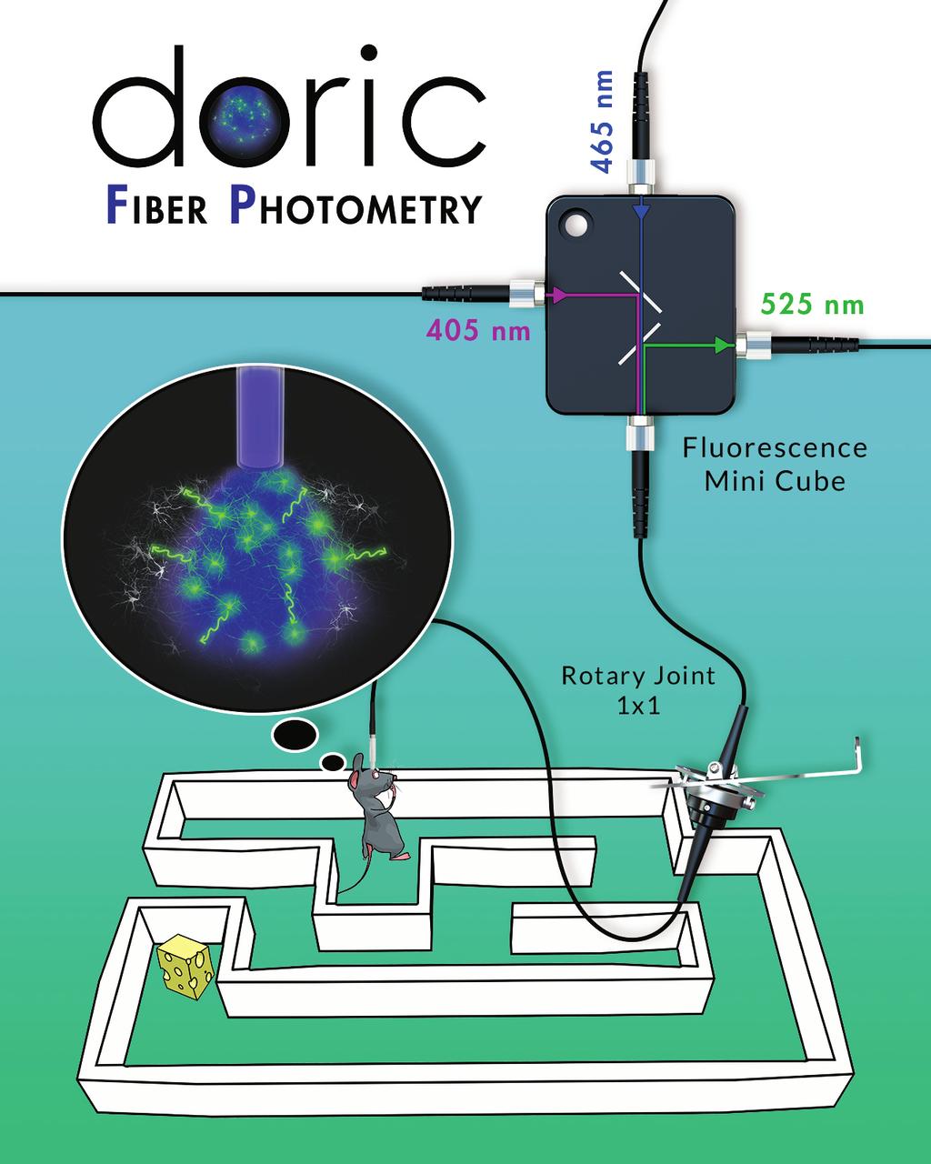
180
Fiber-coupled light sources
 Optogenetics catalog 7.4 - Fiber-coupled light sources 9 Fiber-coupled light sources The fiber optic circuits are driven by light and hence the need to couple the light sources into the optical fiber.
PlexBright LED Optogenetic Stimulation System
 PlexBright LED Optogenetic Stimulation System Introduction Laser-based light sources were the first to make inroads in in vivo optogenetic experimentation, due to their capability of delivering high levels
Lensed Fibers & Tapered Ends Description:
 Lensed Fibers & Tapered Ends Description: LaseOptics Corporation ( LaseOptics ) has been producing next generation optical lensed fibers. LaseOptics Lensed Optical Fibers technology is proprietary integrated
Light Emitting Diodes
 By Kenneth A. Kuhn Jan. 10, 2001, rev. Feb. 3, 2008 Introduction This brief introduction and discussion of light emitting diode characteristics is adapted from a variety of manufacturer data sheets and
Light Delivery Systems for Optogenetics
 Product Catalog and Selection Guide August 2013 Edition Simply Brighter Solutions for Optogenetics WWW.MIGHTEX.COM WWW.MIGHTEXSYSTEMS.COM Mightex Systems 2013 All Rights Reserved. Introduction Optogenetics
Specifications. Mechanical Information. Mass (grams) Dimensions (mm) 15 x 75 Housing. Anodised Aluminium Isolated Body
 Dimensions (mm) 15 x 75 Housing. Anodised Aluminium Isolated Body") Beta TX Datasheet Beta-TX The Beta-TX is a complete self contained laser diode system which can operate in both CW and modulation modes. The Beta- TX features high speed modulation with a bandwidth of
Beta TX Datasheet Beta-TX The Beta-TX is a complete self contained laser diode system which can operate in both CW and modulation modes. The Beta- TX features high speed modulation with a bandwidth of
OPTICAL POWER METER WITH SMART DETECTOR HEAD
 OPTICAL POWER METER WITH SMART DETECTOR HEAD Features Fast response (over 1000 readouts/s) Wavelengths: 440 to 900 nm for visible (VIS) and 800 to 1700 nm for infrared (IR) NIST traceable Built-in attenuator
Industrial Diode Laser (IDL) System IDL Series
 System IDL Series") COMMERCIAL LASERS Industrial Diode Laser (IDL) System IDL Series Key Features Round, top-hat beam profile for uniform power distribution Warranted for full rated power in either pulsed or continuous wave
COMMERCIAL LASERS Industrial Diode Laser (IDL) System IDL Series Key Features Round, top-hat beam profile for uniform power distribution Warranted for full rated power in either pulsed or continuous wave
PRODUCT GUIDE CEL5500 LIGHT ENGINE. World Leader in DLP Light Exploration. A TyRex Technology Family Company
 A TyRex Technology Family Company CEL5500 LIGHT ENGINE PRODUCT GUIDE World Leader in DLP Light Exploration Digital Light Innovations (512) 617-4700 dlinnovations.com CEL5500 Light Engine The CEL5500 Compact
ADVANCED OPTICAL FIBER SOLUTIONS
 Fiber Laser Building Blocks Fiber Laser Cavities and All-Fiber Beam Combiners A Furukawa Company www.ofsoptics.com ADVANCED OPTICAL FIBER SOLUTIONS for Your Next Multi-Kilowatt Fiber Laser Applications
THE NEW LASER FAMILY FOR FINE WELDING FROM FIBER LASERS TO PULSED YAG LASERS
 FOCUS ON FINE SOLUTIONS THE NEW LASER FAMILY FOR FINE WELDING FROM FIBER LASERS TO PULSED YAG LASERS Welding lasers from ROFIN ROFIN s laser sources for welding satisfy all criteria for the optimized laser
USA Price List. January or 8-channel LIBSCAN system (100 mj, 1064 nm laser) Alternative LIBSCAN configurations
 Alternative LIBSCAN configurations") USA Price List January 2012 PRODUCT CODE LIBSCAN 100 LIBSCAN DESCRIPTION 6 or 8-channel LIBSCAN system (100 mj, 1064 nm laser) Includes LIBSCAN head, laser, spectrometer console, interconnecting umbilical
USA Price List January 2012 PRODUCT CODE LIBSCAN 100 LIBSCAN DESCRIPTION 6 or 8-channel LIBSCAN system (100 mj, 1064 nm laser) Includes LIBSCAN head, laser, spectrometer console, interconnecting umbilical
X-Cite XLED1. Advanced LED Illumination for Fluorescence Microscopy. Resetting the standard for LED illumination
 Advanced LED Illumination for Fluorescence Microscopy X-Cite XLED1 Resetting the standard for LED illumination Optimized excitation with high power LED illumination at the sample plane Instant switching
Model 4700 Photodiode Characterizer
 Model 4700 Photodiode Characterizer Complete PD Measurement system The 4700 Photodiode Characterizer is a complete photodiode test system. It will characterize PDs or APDs (upcoming) without the need for
Agilent 83437A Broadband Light Source Agilent 83438A Erbium ASE Source
 Agilent 83437A Agilent 83438A Erbium ASE Source Product Overview H Incoherent light sources for single-mode component and sub-system characterization The Technology 2 The Agilent Technologies 83437A (BBLS)
Laser Beam Analyser Laser Diagnos c System. If you can measure it, you can control it!
 Laser Beam Analyser Laser Diagnos c System If you can measure it, you can control it! Introduc on to Laser Beam Analysis In industrial -, medical - and laboratory applications using CO 2 and YAG lasers,
DPD80 Infrared Datasheet
 Data Sheet v1.4 DPD8 Infrared DPD8 Infrared Datasheet Resolved Inc. www.resolvedinstruments.com info@resolvedinstruments.com 217 Resolved Inc. All rights reserved. DPD8 Infrared General Description The
Light Source. Specification & User Manual
 Light Source Specification & User Manual Page 1 of 11 Copyright 2011 reserves the right to modify specifications without prior notice Table of Contents 1. Description and Features.......3 2. Specification......4
PSM-003. Micro Polarization Controller/Scrambler. User Guide
 PSM-003 Micro Polarization Controller/Scrambler User Guide Version: 1.0 Date: August 23, 2012 General Photonics, Incorporated is located in Chino California. For more information visit the company's website
Leica TCS CARS. Live Molecular Profiling Technical Documentation. Living up to Life
 Leica TCS CARS Live Molecular Profiling Technical Documentation Living up to Life Microscopes Inverted Leica DMI6000 CS Microscope anti-vibration table Specification Vibration insulation Passive Z-drive
In-process inspection: Inspector technology and concept
 Inspector In-process inspection: Inspector technology and concept Need to inspect a part during production or the final result? The Inspector system provides a quick and efficient method to interface a
Color mixing or White-light LED (Light Emitting Diode) ERS-style product
 ERS-style product") WHT Color mixing or White-light LED (Light Emitting Diode) ERS-style product GENERAL PHYSICAL A. The product shall be an Ovation E-910FC as manufactured by Chauvet & Sons, LLC or approved equal. 1. The
WHT Color mixing or White-light LED (Light Emitting Diode) ERS-style product GENERAL PHYSICAL A. The product shall be an Ovation E-910FC as manufactured by Chauvet & Sons, LLC or approved equal. 1. The
25W 9xxnm Uncooled Multimode Laser Diode Module
 25W 9xxnm Uncooled Multimode Laser Diode Module BMU25-9xx-01/02-R Features: Single emitter based laser diode module High output power of 25W 0.15NA or 0.22NA 105μm core multimode optical fiber Hermetically
RGB COMBINERS. 2.0 mm Narrow Key FC/PC or FC/APC Termination Excellent for Confocal. Ø900 µm Loose Hytrel Tube with the wavelength Laser Sources
 RGB COMBINERS Combine Three Input Colors into a Single Output Excellent for Confocal Microscopy, Fluoresence and Other Applications with Multiple Illumination Sources Unterminated, FC/PC, or FC/APC Outputs
OPTICAL MEASURING INSTRUMENTS. MS9710C 600 to 1750 nm OPTICAL SPECTRUM ANALYZER GPIB. High Performance for DWDM Optical Communications
 OPTICAL SPECTRUM ANALYZER 600 to 750 nm GPIB High Performance for DWDM Optical Communications The is a diffraction-grating spectrum analyzer for analyzing optical spectra in the 600 to 750 nm wavelength
Photonics solutions For innovative photonics
 Photonics solutions For innovative photonics 2013 Catalog PRODUCTS CATALOG 2013 A word from us... 1 AnyWave Fiberbench Speckle Scrambler... 2 Polarization control... 5 Hi resolution Polarization control...
SECTION 4 TABLE OF CONTENTS
 Contents Introduction LC, SC and ST Series...4-2 Markets and Applications...4-2 International Standard Documents Compliance...4-2 LC Series Features and Benefits...4-3 LC Standard... 4-4 to 4-5 LC for
OSICS 8-Channel Modular Platform for DWDM Testing
 OSICS 8-Channel Modular Platform for DWDM Testing www.nettest.com ONE INSTRUMENT FULFILLS ALL NEEDS OF DWDM SYSTEMS >Full control of 8 modules in a 19 mainframe > Sophisticated electronics and user friendly
LaserPXIe Series. Tunable Laser Source PRELIMINARY SPEC SHEET
 -1002 1000 Series Tunable Laser Source PRELIMINARY SPEC SHEET Coherent Solutions is a Continuous Wave (CW), tunable laser source offering high-power output, narrow 100 khz linewidth and 0.01 pm resolution
013-RD
 Engineering Note Topic: Product Affected: JAZ-PX Lamp Module Jaz Date Issued: 08/27/2010 Description The Jaz PX lamp is a pulsed, short arc xenon lamp for UV-VIS applications such as absorbance, bioreflectance,
Fiber Type Core/Cladding (um) Rise/ Fall Time Max. (nsec) 850nm GaAlAs VCSEL 1.8V, *indicates internal monitor photodiode)
 Rise/ Fall Time Max. (nsec) 850nm GaAlAs VCSEL 1.8V, *indicates internal monitor photodiode)") PD-. offers a variety of standard Vertical Cavity Surface Emitting Lasers (VCSELs) in ready to use fiber coupled packages. Packaging options include Receptacle style housings such as ST, FC and SC as well
PD-. offers a variety of standard Vertical Cavity Surface Emitting Lasers (VCSELs) in ready to use fiber coupled packages. Packaging options include Receptacle style housings such as ST, FC and SC as well
PV Series 850 nm VCSELs. Rise/ Fall Time Max. (nsec) 850nm GaAlAs VCSEL 1.8V, *indicates internal monitor photodiode)
 850nm GaAlAs VCSEL 1.8V, *indicates internal monitor photodiode)") PD-LD Inc. offers a variety of standard Vertical Cavity Surface Emitting Lasers (VCSELs) in ready to use fiber coupled packages. Packaging options include Receptacle style housings such as ST, FC and SC
PD-LD Inc. offers a variety of standard Vertical Cavity Surface Emitting Lasers (VCSELs) in ready to use fiber coupled packages. Packaging options include Receptacle style housings such as ST, FC and SC
DPD80 Visible Datasheet
 Data Sheet v1.3 Datasheet Resolved Inc. www.resolvedinstruments.com info@resolvedinstruments.com 217 Resolved Inc. All rights reserved. General Description The DPD8 is a low noise digital photodetector
CTP10 KEY FEATURES SPEC SHEET COMPONENT TEST PLATFORM
 COMPONENT TEST PLATFORM Efficiently test passive components in 24/7 operation. Perform single sweep insertion loss and return loss measurements with unprecedented dynamic range, speed and resolution. SPEC
Agilent N7744A 4-Channel Optical Multiport Power Meter N7745A 8-Channel Optical Multiport Power Meter. Fully compliant to LXI Class C specification
 Agilent N7744A 4-Channel Optical Multiport Power Meter N7745A 8-Channel Optical Multiport Power Meter Fully compliant to LXI Class C specification General Information Up to 8 power meter channels in a
Optical Component Environmental Test System
 Data Sheet Optical Component Environmental Test System VIAVI Solutions The Certified VIAVI OCETS (Optical Component Environmental Test System) is the third generation of the classic OCETS, a solution customers
Alternative Fiber Coupler Options
 980 NM, SINGLE MODE FUSED FIBER OPTIC COUPLERS / TAPS Narrowband and Wideband Couplers for 980 nm 50:50, 75:25, 90:10, or 99:1 Coupling Ratio Polarization Insensitive Combine or "Tap Off" Signals FC980-50B-APC
SHOWLINE SL epar 180 LUMINAIRE SPECIFICATIONS.
 SHOWLINE SL epar 180 LUMINAIRE SPECIFICATIONS. GENERAL. A.) Overview. 1.) The luminaire shall be a color mixing luminaire employing nineteen (19) homogenized red, green, blue, and white LED engines. The
Cable Jacket - The outermost layer of the fiber cable. Application: Types Single mode Multi mode. Simplex or Duplex available
 Fiber Optic Products FIBER OPTIC PRODUCTS FIBER OPTIC PATCH CORD CABLE The Construction of a Fiber-Optic Cable Cable Jacket - The outermost layer of the fiber cable. Strengthening fibers - The strengthening
BEAMAGE 3.0 KEY FEATURES BEAM DIAGNOSTICS PRELIMINARY AVAILABLE MODEL MAIN FUNCTIONS. CMOS Beam Profiling Camera
 PRELIMINARY POWER DETECTORS ENERGY DETECTORS MONITORS SPECIAL PRODUCTS OEM DETECTORS THZ DETECTORS PHOTO DETECTORS HIGH POWER DETECTORS CMOS Beam Profiling Camera AVAILABLE MODEL Beamage 3.0 (⅔ in CMOS
20 mm Beam Pitch General Purpose Area Sensor. Distance between parts shelf and sensor can be shortened (Enables miniaturization of equipment)
") OTHER SUNX PRODUCTS SERIES 0 mm Beam Pitch General Purpose Area Sensor Diagnosis Self-diagnosis Test input Interference prevention Wide sensing area of 7 m,60 mm with 0 mm beam pitch Refer to p.9l for
OTHER SUNX PRODUCTS SERIES 0 mm Beam Pitch General Purpose Area Sensor Diagnosis Self-diagnosis Test input Interference prevention Wide sensing area of 7 m,60 mm with 0 mm beam pitch Refer to p.9l for
More Precision. scancontrol // 2D/3D laser scanner (laser profile sensors)
") More Precision scancontrol // 2D/D laser scanner (laser profile sensors) 12 scancontrol 29x gapcontrol 29x1 Technical details and versions - z-axis measuring range up to 265mm - x-axis measuring range
More Precision scancontrol // 2D/D laser scanner (laser profile sensors) 12 scancontrol 29x gapcontrol 29x1 Technical details and versions - z-axis measuring range up to 265mm - x-axis measuring range
ModBox-1310nm-1550nm-NRZ 1310nm & 1550 nm, 28 Gb/s, 44 Gb/s Reference Transmitters
 Fiber The series is a family of Reference Transmitters that generate at 1310 nm and 1550 nm excellent quality NRZ optical data streams up to 28 Gb/s, 44 Gb/s. These Tramsitters offer very clean eye diagram
Measurement of Microdisplays at NPL
 Conference on Microdisplays Measurement of Microdisplays at NPL Christine Wall, Dr Julie Taylor, Colin Campbell 14 th Sept 2001 Overview Displays measurement at NPL Why measure microdisplays? Measurement
Assembly code page 46. Cable code page 47. Assembly classes page 48. Polarization maintaining assemblies page 52
 cable assemblies Assembly code page 46 Cable code page 47 Assembly classes page 48 Polarization maintaining assemblies page 52 45 Assembly: Ordering code Description cable type 27H01CD0- see cable code
SHOWLINE SL NITRO 510 LED STROBE LUMINAIRE SPECIFICATIONS.
 GENERAL. A.) Overview. SHOWLINE SL NITRO 510 LED STROBE LUMINAIRE SPECIFICATIONS. 1.) The luminaire shall be an LED strobe luminaire employing one-thousand, three-hundred and fifty (1350) white LED engines.
Standard Operating Procedure of nanoir2-s
 Standard Operating Procedure of nanoir2-s The Anasys nanoir2 system is the AFM-based nanoscale infrared (IR) spectrometer, which has a patented technique based on photothermal induced resonance (PTIR),
Operating Manual. 50mW C-Band EDFA with GPIB and RS232 Interface
 Fibotec Fiberoptics GmbH Herpfer Str. 40 98617 Meiningen Germany Tel. +49 3693 8813-200 Fax. +49 3693 8813-201 www.fibotec.com Operating Manual 50mW C-Band EDFA with GPIB and RS232 Interface (Version 1.1
SPECIAL SPECIFICATION 6911 Fiber Optic Video Data Transmission Equipment
 2004 Specifications CSJ 3256-02-079 & 3256-03-082 SPECIAL SPECIFICATION 6911 Fiber Optic Video Data Transmission Equipment 1. Description. Furnish and install Fiber Optic Video Data Transmission Equipment
LED modules for illuminated signs Opto Semiconductors
 New creativity in lighting design LED modules for illuminated signs Opto Semiconductors Illuminated signs with LED modules. Modern. Professional. Creative. An excellent way to advertise: LED modules (BACKlight,
6 3 0 N M, S I N G L E M O D E F U S E D F I B E R O P T I C C OUPLERS / TA P S
 6 3 0 N M, S I N G L E M O D E F U S E D F I B E R O P T I C C OUPLERS / TA P S Narrowband and Wideband Couplers for 630 nm Available with 50:50, 75:25, 90:10, or 99:1 Terminated with 2.0 mm Narrow Key
ModBox-1310nm-1550nm-28Gbaud-PAM nm & 1550 nm, 28 Gbaud PAM-4 Reference Transmitter
 -1310nm-1550nm-28Gbaud-PAM4 The -1310nm-1550nm-28Gbaud-PAM4 is a dual wavelength 1310 nm and 1550 nm Linear Reference Transmitter that generates excellent quality optical data streams PAM-4 up to 28 Gbaud
SHOWLINE SL NITRO 510C LED STROBE LUMINAIRE SPECIFICATIONS.
 GENERAL. A.) Overview. SHOWLINE SL NITRO 510C LED STROBE LUMINAIRE SPECIFICATIONS. The luminaire shall be an LED strobe luminaire employing five hundred and twenty eight (528) red, green, blue and white
1995 Metric CSJ SPECIAL SPECIFICATION ITEM 6031 SINGLE MODE FIBER OPTIC VIDEO TRANSMISSION EQUIPMENT
 1995 Metric CSJ 0508-01-258 SPECIAL SPECIFICATION ITEM 6031 SINGLE MODE FIBER OPTIC VIDEO TRANSMISSION EQUIPMENT 1.0 Description This Item shall govern for the furnishing and installation of color Single
Cladding Pumped Amplifier Using Seven-core EDF
 Cladding Pumped Amplifier Using Seven-core EDF Koichi Maeda *1, Shigehiro Takasaka *1, Ryuichi Sugizaki *1, Yukihiro Tsuchida *2, Kengo Watanabe *2, Tsunetoshi Saito *3 We have developed a multicore erbium
DESIGN OF VISIBLE LIGHT COMMUNICATION SYSTEM
 DESIGN OF VISIBLE LIGHT COMMUNICATION SYSTEM *Vishakh B V, **Mohammed Kamal Khwaja *School of Electronics Engineering, VIT University, Vellore, India ** School of Electronics Engineering, VIT University,
KVANT. Spectrum 1,6W RGB laser system. Product datasheet
 KVANT Spectrum 1,6W RGB laser system Product datasheet SPECTRUM series professional full colour laser system 1. DESCRIPTION Kvant Spectrum is professional laser system with wide range of use, mainly for
Mini-spectrometers. TM series. High sensitivity type (integrated with backthinned type CCD image sensor) C10082CA/C10083CA series
 C10082CA/C10083CA series") C12CA/C1CA series type (integrated with backthinned type CCD ) mini-spectrometers are polychromators integrated with optical elements, an and a driver circuit. Light to be measured is guided into the entrance
C12CA/C1CA series type (integrated with backthinned type CCD ) mini-spectrometers are polychromators integrated with optical elements, an and a driver circuit. Light to be measured is guided into the entrance
VersiVision. FVTM2BBxA / FVRM2BBxA 2-CHANNELS DIGITALLY ENCODED VIDEO 2-CHANNELS BI-DIRECTIONAL DATA 2-CHANNELS BI-DIRECTIONAL AUDIO
 VersiVision FVTM2BBxA / FVRM2BBxA 2-CHANNELS DIGITALLY ENCODED VIDEO 2-CHANNELS BI-DIRECTIONAL DATA 2-CHANNELS BI-DIRECTIONAL AUDIO TRANSMITTER / RECEIVER MULTIPLEXERS USER S MANUAL Revision B April 2013
SPATIAL LIGHT MODULATORS
 SPATIAL LIGHT MODULATORS Reflective XY Series Phase and Amplitude 512x512 A spatial light modulator (SLM) is an electrically programmable device that modulates light according to a fixed spatial (pixel)
LEDs, New Light Sources for Display Backlighting Application Note
 LEDs, New Light Sources for Display Backlighting Application Note Introduction Because of their low intensity, the use of light emitting diodes (LEDs) as a light source for backlighting was previously
Optical Perfection. HIGHYAG Beam Delivery Products
 Optical Perfection HIGHYAG Beam Delivery Products At a Glance HIGHYAG Beam Delivery Products HIGHYAG beam delivery products for 1 µ lasers - from the beam launching unit at the laser via the laser light
SHOWLINE SL PUNCHLITE 220 LED LUMINAIRE SPECIFICATIONS.
 SHOWLINE SL PUNCHLITE 220 LED LUMINAIRE SPECIFICATIONS. GENERAL. A.) Overview. 1.) The luminaire shall be a color mixing luminaire employing nine (19) homogenized red, green, blue, and white LED engines.
Fiber Optic Testing. The FOA Reference for Fiber Optics Fiber Optic Testing. Rev. 1/31/17 Page 1 of 12
 Fiber Optic Testing Testing is used to evaluate the performance of fiber optic components, cable plants and systems. As the components like fiber, connectors, splices, LED or laser sources, detectors and
SHOWLINE SL BAR 640 LINEAR WASH LUMINAIRE SPECIFICATIONS.
 GENERAL. A.) Overview. SHOWLINE SL BAR 640 LINEAR WASH LUMINAIRE SPECIFICATIONS. 1.) The luminaire shall be a color mixing luminaire employing twenty-four (24) red, green, blue, and white LED engines.
Advanced Test Equipment Rentals ATEC (2832)
") E stablished 1981 Advanced Test Equipment Rentals www.atecorp.com 800-404-ATEC (2832) Technical Datasheet Scalar Network Analyzer Model 8003-10 MHz to 40 GHz The Giga-tronics Model 8003 Precision Scalar
E stablished 1981 Advanced Test Equipment Rentals www.atecorp.com 800-404-ATEC (2832) Technical Datasheet Scalar Network Analyzer Model 8003-10 MHz to 40 GHz The Giga-tronics Model 8003 Precision Scalar
VersiVision. FVTMHA0xA / FVRMHA0xA 16-CHANNEL DIGITALLY ENCODED VIDEO 1-CHANNEL BI-DIRECTIONAL DATA MULTIPLEXER USER S MANUAL.
 VersiVision FVTMHA0xA / FVRMHA0xA 16-CHANNEL DIGITALLY ENCODED VIDEO 1-CHANNEL BI-DIRECTIONAL DATA MULTIPLEXER USER S MANUAL Revision B April 2013 VERSITRON, Inc. 83 Albe Drive / Suite C Newark, DE 19702
A dedicated data acquisition system for ion velocity measurements of laser produced plasmas
 A dedicated data acquisition system for ion velocity measurements of laser produced plasmas N Sreedhar, S Nigam, Y B S R Prasad, V K Senecha & C P Navathe Laser Plasma Division, Centre for Advanced Technology,
POLARIZED FIBER OPTIC SOURCE
 219 Westbrook Rd, Ottawa, ON, Canada, K0A 1L0 Toll Free: 1-800-361-5415 Tel:(613) 831-0981 Fax:(613) 836-5089 E-mail: sales@ozoptics.com Features: High polarization extinction ratio (up to 40 db) Stable
Spectroscopy Module. Vescent Photonics, Inc E. 41 st Ave Denver, CO Phone: (303) Fax: (303)
 Fax: (303)") Spectroscopy Module Vescent Photonics, Inc. www.vescentphotonics.com 4865 E. 41 st Ave Denver, CO 80216 Phone: (303)-296-6766 Fax: (303)-296-6783 General Warnings and Cautions The following general warnings
Spectroscopy Module Vescent Photonics, Inc. www.vescentphotonics.com 4865 E. 41 st Ave Denver, CO 80216 Phone: (303)-296-6766 Fax: (303)-296-6783 General Warnings and Cautions The following general warnings
FiberLink 7142 Series
 MANUAL FiberLink 7142 Series 4 Channels of Composite Video and 8 Channels of Audio over one single mode or multimode fiber Installation and Operations Manual WWW.ARTEL.COM FibeLink 7142 Series Contents
SPECIAL SPECIFICATION 1291 Fiber Optic Video Data Transmission Equipment
 1993 Specifications CSJ 0500-01-117 SPECIAL SPECIFICATION 1291 Fiber Optic Video Data Transmission Equipment 1. Description. This Item shall govern for the furnishing and installation of Fiber Optic Video
Altman Lighting Spectra Cyc 50 Specification
 1.01 CYCLORAMA LIGHTING A. General 1. The fixture shall be a compact, lightweight color-mixing LED asymmetrical wash fixture with 8 or 16 bit DMX control of intensity and color. The fixture shall be the
Agilent 86120B, 86120C, 86122A Multi-Wavelength Meters Technical Specifications
 Agilent 86120B, 86120C, 86122A Multi-Wavelength Meters Technical Specifications March 2006 Agilent multi-wavelength meters are Michelson interferometer-based instruments that measure wavelength and optical
ET-5050x-BF1W Datasheet
 PLCC Series ET-5050x-BF1W Datasheet Features : High luminous Intensity and high efficiency Based on GaN technology Wide viewing angle : 120 Excellent performance and visibility Suitable for all SMT assembly
Advanced Test Equipment Rentals ATEC (2832)
") Established 1981 Advanced Test Equipment Rentals www.atecorp.com 800-404-ATEC (2832) For more information about Agilent Technologies test and measurement products, applications, services, and for a current
Established 1981 Advanced Test Equipment Rentals www.atecorp.com 800-404-ATEC (2832) For more information about Agilent Technologies test and measurement products, applications, services, and for a current
CBF500 High resolution Streak camera
 High resolution Streak camera Features 400 900 nm spectral sensitivity 5 ps impulse response 10 ps trigger jitter Trigger external or command 5 to 50 ns analysis duration 1024 x 1024, 12-bit readout camera
We will look first at the cable, and then the transceivers (which act as both transmitter and receiver on each end of the fiber cable).
.") Nuclear Sensors & Process Instrumentation Fiber Cable Basics Fiber-optic communication is a method of transmitting information from one place to another by sending light through an optical fiber. The light
Nuclear Sensors & Process Instrumentation Fiber Cable Basics Fiber-optic communication is a method of transmitting information from one place to another by sending light through an optical fiber. The light
OFI-400 Series Optical Fiber Identifiers. OFI-400 Series Models
 OFI-400 Series Optical Fiber Identifiers Quick Reference Guide MODEL FIBER SIZE DESCRIPTION AND FUNCTION OFI-400 SM fibers: 250 µm coated 900 µm coated Ribbon 2 mm jacketed 3 mm jacketed Designed for use
MAFA 5000 Series Erbium Doped Fiber Preamplifier
 CATV & MICROWAVE The EMCORE MAFA 5000 Series Micro Erbium Doped Fiber Preamplifier gain block module is an ideal building block for OEM systems integration where there is a requirement to pre-amplify a
SPECIAL SPECIFICATION 1987 Single Mode Fiber Optic Video Transmission Equipment
 1993 Specifications CSJ 0027-12-086, etc. SPECIAL SPECIFICATION 1987 Single Mode Fiber Optic Video Transmission Equipment 1. Description. This Item shall govern for the furnishing and installation of color
VIDEO 101 LCD MONITOR OVERVIEW
 VIDEO 101 LCD MONITOR OVERVIEW This provides an overview of the monitor nomenclature and specifications as they relate to TRU-Vu industrial monitors. This is an ever changing industry and as such all specifications
MULTIDYNE INNOVATIONS IN TELEVISION TESTING & DISTRIBUTION DIGITAL VIDEO, AUDIO & DATA FIBER OPTIC MULTIPLEXER TRANSPORT SYSTEM
 MULTIDYNE INNOVATIONS IN TELEVISION TESTING & DISTRIBUTION INSTRUCTION MANUAL DVM-1000 DIGITAL VIDEO, AUDIO & DATA FIBER OPTIC MULTIPLEXER TRANSPORT SYSTEM MULTIDYNE Electronics, Inc. Innovations in Television
Selection of a cable depends on functions such as The material Singlemode or multimode Step or graded index Wave length of the transmitter
 Fibre Optic Communications The greatest advantage of fibre cable is that it is completely insensitive to electrical and magnetic disturbances. It is therefore ideal for harsh industrial environments. It
OFI Optical Fiber Identifier User s Guide
 OFI Optical Fiber Identifier User s Guide OFI Optical Fiber Identifier User s Guide 2002-2008, AFL Telecommunications, all rights reserved. OFI1-11-1000 Revision A, 05.02.08 Specifications are subject
Benchtop/Rackmount Programmable Switches. Key Features & Benefits. SB/SC/SCG Series. Applications INSTRUMENTATION CATALOGUE - 73
 Benchtop/ackmount Programmable Switches SB/SC/SCG Series The JDS Uniphase SB, SC, and SCG series of Benchtop/ ackmount Programmable Switches can be controlled using the front panel keys and a numeric pad
SatellitePlus Model OLAT/OLAR. Advanced L-Band Series. 10-4,000 MHz OPERATING MANUAL
 SatellitePlus Model OLAT/OLAR Advanced L-Band Series 10-4,000 MHz OPERATING MANUAL 24926 Highway 108 Sierra Village, CA 95346 Phone: (800) 545-1022 Fax: (209 586-1022 025-000570 Rev. X7 E-Mail: sales@olsontech.com
MOST - Roadmap Physical Layer & Connectivity from 150Mbps to 5Gbps
 MOST - Roadmap Physical Layer & Connectivity from 150Mbps to 5Gbps 13th MOST(R) Interconnectivity Conference Asia on November 15, 2012 in Seoul, South Korea Andreas Engel Manager Advanced Infotainment
SmartCrystal Cinema Neo
 Model VPSP-11100 www.volfoni.com 1 SUMMARY SUMMARY... 2 I. PRODUCT OVERVIEW... 3 II. REQUIREMENTS... 3 III. SMARTCRYSTAL CINEMA NEO FEATURES... 5 A. General specifications... 5 B. Technical specifications...
Contents. 1. System Description 3. Overview 3 Part Names 3 Operating Conditions 7 Start-up Procedure 7. 2.
 Rigel 1550 Terahertz Spectrometer User Manual Contents info@tetechs.com 1. System Description 3 Overview 3 Part Names 3 Operating Conditions 7 Start-up Procedure 7 2. Safety 9 Laser Safety 9 Electrical
Spatial Light Modulators XY Series
 Spatial Light Modulators XY Series Phase and Amplitude 512x512 and 256x256 A spatial light modulator (SLM) is an electrically programmable device that modulates light according to a fixed spatial (pixel)
Multiple Band Outdoor Block Up- and Downconverters
 Multiple Band Outdoor Block Up- and Downconverters Vertical Mount Option RF IF LO Frequency Frequency Frequency Model Band (GHz) (MHz) (GHz) Number Block Upconverters 1 12.75 13.25 0.95 1.45 11.8 UPB2-WS-13.625
TIL311 HEXADECIMAL DISPLAY WITH LOGIC
 TIL311 Internal TTL MSI IC with Latch, Decoder, and Driver 0.300-Inch (7,62-mm) Character Height Wide Viewing Angle High Brightness Left-and-Right-Hand Decimals Constant-Current Drive for Hexadecimal Characters
Projection Displays Second Edition
 Projection Displays Second Edition by Matthew S. Brennesholtz Insight Media, USA Edward H. Stupp Stupp Associates, USA WILEY A John Wiley and Sons, Ltd, Publication Contents Foreword Preface to the Second
LVM LASER VALVE MOTION measurement system LASER-BASED TECHNOLOGY. SIMULTANEOUS, REAL-TIME DISPLACEMENT, VELOCITY and ACCELERATION ANOLOG OUTPUTS
 LVM-4000 LASER VALVE MOTION measurement system OH-1000 LASER VIBROMETER HEAD LASER-BASED TECHNOLOGY SIMULTANEOUS, REAL-TIME DISPLACEMENT, VELOCITY and ACCELERATION ANOLOG OUTPUTS ENGINE HEAD VIBRATION
Smart Lighting Demos
 Smart Lighting Demos The following are demos and hands-on activities to provide additional background for smart lighting. Cypress CapSense EZ Color CY 3263N Starter Demo Kit Cypress Semiconductor's CY3269N
SHOWLINE SL PAR 155 LED LUMINAIRE SPECIFICATIONS.
 SHOWLINE SL PAR 155 LED LUMINAIRE SPECIFICATIONS. GENERAL. A.) Overview. 1.) The luminaire shall be a color mixing luminaire employing nine (9) homogenized red, green, blue, and white LED engines. The
OLS Series Light Sources, OPM Series Optical Power Meters, and Related Test Kits User s Guide
 OLS Series Light Sources, OPM Series Optical Power Meters, and Related Test Kits User s Guide Limited Warranty One Year Limited Warranty All Noyes products are warranted against defective material and
Fiber Optics Redefined
 Fiber Optics Redefined Questions and Answers on the basics of fiber optic installation TECHLOGIX NETWORX Questions & Answers Questions and Answers Q: What are the two main types of fiber? A: The two main
Building Your Own 2-Photon Microscope: Challenges, Advantages and Limitations
 Building Your Own 2-Photon Microscope: Challenges, Advantages and Limitations Roberto Weigert, Ph.D. Chief, Intracellular Membrane Trafficking Section Oral and Pharngeal Cancer Branch NIDCR-NIH Building