RAD 465 (MRI) Lecture one (Pulse Sequences) Ruba Khushaim MSc
|
|
|
- Emery Watson
- 5 years ago
- Views:
Transcription
1 RAD 465 (MRI) Lecture one (Pulse Sequences) Ruba Khushaim MSc
2 Outline : Spine echo pulse sequence SE Fast spin echo pulse sequence FSE Inversion recovery pulse sequence IR Gradient pulse sequence GS
3 Pulse sequences Pulse sequence definition: is a series of RF pulses, gradients application and intervening time periods The pulse sequence can control: 1. Slice location 2. Slice thickness 3. Number of the slice 4. Resolution (FOV and matrix) 5. Image contrast (TR, TE, TI, flip angle and diffusion 6. Artifact correction (for example: saturation pulse, flow compensate and fat suppression)
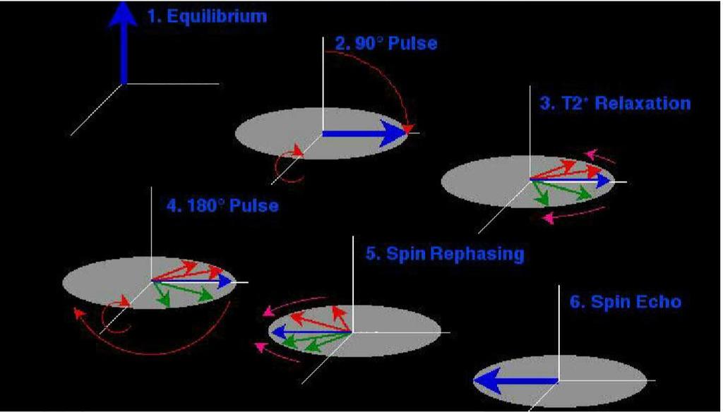
4 Spin echo (conventional spin echo SE) In the spin echo pulse sequence usually 90 excitation RF pulse followed by a 180 (rephrasing) pulse (one or two) is used to produce the signal SE pulse sequences are the most commonly applied sequences as they produce image with ideal signal and ideal contrast ₁ We can produce T1,T2 or PD weighted images by select the TR and TE.
5 What are the TR and TE? The repetition time (TR) : is the time between successive 90 RF excitation pulses is it controls the amount of recovery allowed in longitudinal plane to enhance the contrast between tissues The echo time: is the time between the applied 90 RF pulse and the center of the acquisition. It controls the amount of dephasing allowed in the transverse plane to enhance the contrast between tissues
6 MRI in Practice page 143
7
8 Using of the spin echo pulse sequence T1 weighted image has (short TE and short TR) which is useful to show the anatomy T1 weighted image + contrast media is used to demonstrate the enhancement of the pathology with contrast media. T2 weighted image is acquired with (long TE and long TR) which demonstrates the pathology PD weighted is acquired with (short TE and long TR)
9 Advantages and disadvantages of SE: Advantages: Good image quality with high SNR Easy to understand the image contrast Less artifact in the image T2 weighted is sensitive to pathology Disadvantages: Scan time is long TR is long so it is not suitable to 3D acquesation SAR is higher than gradient pulse sequence WHY?
10 Scan time in SE: scan time min = TRmsec NEX # phase encoding 60000
11 Reduce the scan time As the scan time is a function of the TR, NEX and number of phase encoding, in order to reduce the scan time, one or more of these factors should be reduced.
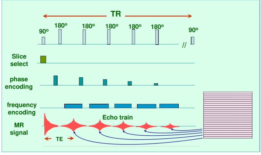
12 Fast spin echo or turbo spin echo Fast spin echo (FSE) uses a 90 flip angle followed by several 180 rephasing pulses to produce several SE in a given TR In the FSE all the echoes are collected with same slice selection gradient amplitude However, each echo has different phase encoded amplitude of gradient slope, so the data from each echo are collected and stored in a different line of k- space.
13 Fast spin echo or turbo spin echo Number of the 180 rephasing pulses applied known as echo train length ETL or turbo facto. In the FSE more than one line are filled in the k-space each TR. So the scan time decrease by ETL scan time min = TRmsec NEX # phase encoding ETL
14
15 Single-shot FSE (SS-FSE) Single- shot can be named as HASTE (half acquisition single-shot turbo spin echo) This pulse sequence has long ETLs that fill all of k-space in one shot with half- Fourier acquisition techniques In this technique only half of k-space are acquired and then transfer data into the other half. The adventage of this technique that it is very rapid acquisitions, which is used in multiple-slice breath-hold and real-time imaging
16 Single-shot FSE (SS-FSE) Disadvantages: 1. less SNR as only half the k-space data really acquired 1. Higher SAR (specific absorption rate) Solution can be used to decrease the SAR if necessary? Use less refocussing pulse rather than 180 (for example 120 degree); however, that will drop the SNR
17 Advantages of the FSE: Advantages: Decrease the scan time by ETL Higher resolution and multiple NEX to improve the SNR Although the contrast in the FSE is similar to SE; however, there are some differences. In the central nervous system, pelvis and musculoskeletal resign FSE has replaced the SE (especially in T2)
18 Disadvantages of the FSE: 1- One of these differences is that fat remains bright on T2-weighted images and fat suppression techniques may be needed to compensate for this. Why does the fat remain bright on T2- Weighted image? Because the multiple 180 RF pulses used in FSE sequences leads to lengthening of the T2 decay time of fat that the signal intensity of fat on T2W in FSE images is higher than in SE.
19 Disadvantages of the FSE: 2- some of the flow and motion affects increased. 3- required a special hardware and software 4- Too much acoustic noise which need double hearing protection
20 Disadvantages of the FSE: 5- In addition to that, in FSE sequences, artifact as blurring in the image is often come up with long ETL sequences. This occurs because each line of k-space contains data from echoes with a different TE. When long ETL sequences is used, the very late echoes have a low signal amplitude and, as the outer lines of k-space are filled with data from these echoes, there are insufficient data to provide adequate resolution. Image blurring is most commonly seen at the edges of tissues with different T2 decay times. The blurring is increase with long echo train length

21 Physical basis of MRI Dr. Abdullah Jamea
22 Disadvantages of the FSE: That blurring can be reduced by decreasing the size of the FOV in the phase direction or by selecting a broad receive bandwidth. What is the parameter trade-off come up with these two solutions? However, these solutions improve overall image quality by reducing blurring, but they also reduces the SNR. Lastly, FSE is not always compatible with options such as phase-reordered RC, and therefore, conventional SE or breath-hold sequences are often the sequence of choice with respiratory artefact.
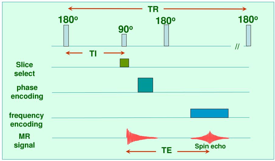
23 Inversion recovery (IR/IR-FSE) It was used a t the begging to produce a good T1 contrast in low field system ₂ IR pulse sequences begin with a 180 pulse that inverts the net magnetization into ( Z axis) which known as full saturation The magnetization begins to recover and return towards B0 (Z axis) after the 180 inverted pulse removed After a specific time TI (inversion time), a 90 RF pulse is applied to transfers the magnetization that has recovered to B0 into the transverse plane In IR-FSE, several 180 rephasing pulses are applied as in FSE, so that more than one line of k-space can be filled per TR, so reducing the scan times.
24
25 Inversion recovery types: At the beginning the IR is most commonly used to produce heavily T1-weighted images. Because there is a big contrast difference between the fat and the water. But IR and IR-FSE can be used to suppress the signal from any tissues. by applying the 90 excitation pulse when the magnetization in that tissue has recovered into the transverse plane and therefore no longitudinal component of that tissue. IT = 0.69 (T1 relaxation time for nulling tissue).
26 Inversion recovery types: In the IR pulse sequences, the contrast in the image depend on TI in addition to other contrast parameters. The TI is also depend on the field strength.
27 Advantages and disadvantages: Advantages: 1. Good SNR the TR is long 2. Give a good T1 contrast + a good enhancement of the tissue when the contrast media given Disadvantages: Longer scan time unless it is used with FSE
28 The type of the inversion recovery(ir) There are two main uses of the IR: STIR and FLAIR STAIR (short tau inversion recovery) has short inversion time to nulling the signal from the fat. STIR is not suitable to be used with contrast media enhancement. Why? Because the enhancement tissue will be shorten their T1 relaxation make them near from the fat and they null as well FLAIR (fluid attenuation inversion recovery) which has long inversion time to nulling the signal from the cerebrospinal fluid (CSF).
29 Using of the FLAIR It is used in the brain and spin to visualize periventricular and cord lesion (multiple sclerosis, subarachnoid hemorrhage and meningitis)
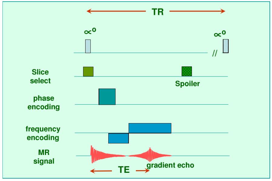
30 Gradient pulse sequences: The gradient pulse sequence use a flip angle different than 90 + using a frequency encoding gradient to rephase the FID pulse instead of 180 pulse in the SE pulse sequence So the TR decrease, and T2* and PD image contrast can be acquired with less time The TE will decrease as well Frequency encoding gradient is applied negatively (to increase the dephase the FID and then positively (to refocus the signal)
31 Gradient pulse sequences: However, the gradient will not be able to eliminate inhomogeneities of the magnetic field, so the T2* relaxation will have effect on the image contrast. Uses : 1. Acquiring T2*, T1 or proton density image contrast 2. Produce a single-slice or volume breathe hold in the abdominal 3. Dynamic contrast enhancement 4. Angiography ( because the GS sensitive to the blood flow)
32 Advantages and disadvantages of the gradient echo: advantages faster imaging can use shorter TR and shorter TE than SE low flip angle deposits less energy more slices per TR than SE compatible with 3D acquisitions
33 Advantages and disadvantages of the gradient echo: Disadvantages: 1. Difficult to generate good T2 weighting 2. magnetic field inhomogeneities cause signal loss 3. The disadvantages worse with increasing TE times 4. susceptibility effects increase 5. dephasing of water and fat protons
34
35 There are different type of the Gradient echo The signal can be produced from the spin in the longitudinal magnetization M z,( or and ) part from the steady state (transverse magnetization) M xy
36 1- Incoherent(spoiled)gradient echo (T1/PD) (SPGR, T1 FFE OR FLASH (fast low angle shot ) Use variable flip angle + gradient rephrasing (instead of in the spin echo sequence). The signal come from the longitudinal magnetization only for the next excitation. As the transverse magnetization (the spins in the transvers plane from the previous pulse) has been spoiled or diphase to reduce the effect of the T2 or T2* This pulse sequence produce T1 WI and PD.
37
38 Advantages and disadvantages of the Incoherent (spoiled) gradient echo: Advantages: Produce T1 weighted image in the breath hold technique image (liver and chest). Showing the anatomy and pathology in the post contrast image. Can be used for 2D or 3D image. Disadvantages: Prone to the artifact Less SNR (as the transvers magnetization is spoiled)
39 2- gradient echo (T2*) (GRASS/2-Coherent FFE/FISP) Use a variable flip angle followed by gradient rephasing to produce a GR echo. This is achieved by a reversal of the phase encoding gradient prior to each repetition that rephases this transverse magnetization. In this way, the coherence of the transverse magnetization is maintained, so that mainly signal steady state GRE images represents a mixed contribution from both the longitudinal and transverse components of the tissue magnetization by using a reminder gradient. It is usually used in angiography because it is sensitive to the flow Fast scan and can produce volume imaging or breath hold technique
40
41 Homework: Q1 From the clinical application give an example of difficulties in the diagnosis of some of the pathology come up with different in the contrast between the FSE and SE? Then give a solution can be given to solve this problem?
42 References: 1. Handbook of MRI Technique, Fourth Edition. Catherine Westbrook John Wiley & Sons, Ltd. Published 2014 by John Wiley & Sons, Ltd. Companion website: 2. MRI in practice, Forth Edition. Catherine Westbrook, Carolyn Roth & John Talbot 3. physical basis of MRI pulse sequences review. Abdullah Jamea
Abstract. Learning Objectives 8/1/2017
 SAM Practical Medical Physics TU-B-201-0 AAPM Annual Meeting 2017 1 Abstract This course will teach the participant to identify common artifacts found clinically in MR, DR, CT, PET, to determine the causes
M R I Physics Course. Jerry Allison Ph.D. Chris Wright B.S. Tom Lavin M.S.M.P. Department of Radiology Medical College of Georgia
 M R I Physics Course Jerry Allison Ph.D. Chris Wright B.S. Tom Lavin M.S.M.P. Department of Radiology Medical College of Georgia M R I Physics Course chapter 12 Artifacts and Suppression Techniques Artifacts
EPI. Thanks to Samantha Holdsworth!
 EPI Faster Cartesian approach Single-shot, Interleaved, segmented, half-k-space Delays, etc -> Phase corrections Flyback EPI GRASE Thanks to Samantha Holdsworth! 1 EPI: Speed vs Distortion Fast Spin Echo
MSK Imaging Fundamentals
 MSK Imaging Fundamentals Goals Improve image quality Provide best possible product for our customers Patient Referring clinician Radiologist Reduce number of callback cases Goal reduction of 50% in 3 months
HITACHI S FAST SPIN ECHO TECHNOLOGY
 primefse TECHNOLOGY Yosuke Hitata RT Makoto Sasaki MD Kunio Esashika RT Hiroshi Gakumazawa RT HITACHI S FAST SPIN ECHO TECHNOLOGY Efficacies in Improving Image Quality & Usability Hitachi Medical Systems
4/14/2009. The Big Picture of Quality. MRI Quality Assurance and ACR MRI Accreditation Program. Basic Elements for Image Quality.
 The Big Picture of Quality MRI Quality Assurance and ACR MRI Accreditation Program Chen Lin, PhD Indiana University School of Medicine & Clarian Health Partners Diagnosis accuracy Image quality Knowledge
Artifacts in Abdominopelvic MR A Pictorial Review
 Artifacts in Abdominopelvic MR A Pictorial Review Evan Allgood, MD Radiology Resident Harbor - University of California, Los Angeles Bijan Bijan, MD, MBA Professor of Radiology & Nuclear Medicine (WOS)
PATIENT POSITION IMAGING PARAMETERS
 3 PLANE LOC Patient Entry Feet First Imaging Mode 2D Patient Position Prone Pulse Sequence Gradient Echo Coil Configuration 7breast both MRI Imaging Options Seq, Fast Plane 3-PLANE Acceleration Factor
Breast MR Imaging and Quality Control
 Breast MR Imaging and Quality Control Donna M. Reeve, MS, DABR, DABMP Department of Imaging Physics Educational Objectives 1. Provide an overview of breast MR imaging and MR-guided biopsy procedures. 2.
Practicum 3, Fall 2012
 A.- F. Miller 2012 T1&T2 Measurement 1 Practicum 3, Fall 2012 Measuring the longitudinal relaxation time: T1. Strychnine, dissolved CDCl3 The T1 is the characteristic time of relaxation of Z- magnetization,
Image quality in non-gated versus gated reconstruction of tongue motion using Magnetic Resonance Imaging:
 This talk was presented 26 June 2008, at the 22nd International Congress and Exhibition of Computer Assisted Radiology and Surgery, in Barcelona at the Hotel Constanza from June 25 to 28, 2008. See http://kochanski.org/gpk/papers/2008/carstalk.html
True comfort and flexibility with the power of 3T.
 True comfort and flexibility with the power of 3T. With a large 71 cm aperture and the quietest exams in the industry, the Vantage Titan 3T is the most comfortable 3T MRI system for all of your patients.
Experiences in ACR MRI Accreditation Vendor Nuances That Every Clinical MRI Physicist Should Know
 Experiences in ACR MRI Accreditation Vendor Nuances That Every Clinical MRI Physicist Should Know By Kathryn (Kat) W. Huff, M.S., DABR Prepared for The 2013 AAPM Spring Clinical Meeting Validating Me I
Practicum 3, Fall 2010
 A. F. Miller 2010 T1 Measurement 1 Practicum 3, Fall 2010 Measuring the longitudinal relaxation time: T1. Strychnine, dissolved CDCl3 The T1 is the characteristic time of relaxation of Z magnetization
Nuclear Associates and
 Nuclear Associates 76-907 and 76-908 AAPM MRI Phantoms Users Manual March 2005 Manual No. 38616 Rev. 3 2003, 2005 Fluke Corporation, All rights reserved. Printed in U.S.A. All product names are trademarks
Chapter 7. Scanner Controls
 Chapter 7 Scanner Controls Gain Compensation Echoes created by similar acoustic mismatches at interfaces deeper in the body return to the transducer with weaker amplitude than those closer because of the
Requirements for Imaging
 Requirements for Imaging Max Seidensticker Universitätsklinikum Magdeburg Klinik für Radiologie & Nuklearmedizin SORAMIC 1 Requirements for Imaging SORAMIC: Evaluation of Sorafenib and microtherapy guided
(12) Patent Application Publication (10) Pub. No.: US 2008/ A1. (51) Int. Cl. be maintained. GRADENT SYSTEM PHYSOLOGICAL ACQUESTION CONTROLLER
 Patent Application Publication (10) Pub. No.: US 2008/ A1. (51) Int. Cl. be maintained. GRADENT SYSTEM PHYSOLOGICAL ACQUESTION CONTROLLER") (19) United States (12) Patent Application Publication (10) Pub. No.: US 2008/0116891 A1 Van der KOuWe et al. US 2008O1 16891A1 (43) Pub. Date: May 22, 2008 (54) (76) (21) (22) SYSTEMAND METHOD FOR MULT-ECHO
(19) United States (12) Patent Application Publication (10) Pub. No.: US 2008/0116891 A1 Van der KOuWe et al. US 2008O1 16891A1 (43) Pub. Date: May 22, 2008 (54) (76) (21) (22) SYSTEMAND METHOD FOR MULT-ECHO
Open Your Vision Make a Smart Choice
 0.4T x open design APERTO Lucent offers sophisticated MR imaging with a 0.4T permanent magnet in a compact, patient-focussed gantry. Hitachi s technological expertise enabled the design and creation of
Peacefully quiet. Remarkably fast.
 Peacefully quiet. Remarkably fast. Excellent image quality Streamlined workflow Outstanding patient comfort Canon Medical Systems Vantage Galan 3T offers a transformational experience for you and your
NMR. picospin. Maintenance Guide
 NMR picospin Maintenance Guide 269-302600 Revision A January 2013 2013 Thermo Fisher Scientific Inc. All rights reserved. For U.S. Technical Support, please contact: Thermo Fisher Scientific 5225 Verona
WHY CHOOSE HITACHI? * Based on Hitachi's factory shipment records, as of end of March, Others 743 EUROPE.
 WHY CHOOSE HITACHI? For more than 30 years, Hitachi has been leading the way in Open MRI. With more than 7,000 systems delivered worldwide*, Hitachi is at the forefront of MRI technology. * Based on Hitachi's
GS Bloch Equations Simulator 1. GS Introduction to Medical Physics IV Exercise 1: Discrete Subjects
 GS02-1193 Bloch Equations Simulator 1 GS02-1193 Introduction to Medical Physics IV Exercise 1: Discrete Subjects Once SpinWright is running, select the Subject tab. The GUI display toward the top of the
Comparison of Robarts s 3T and 7T MRI Machines for obtaining fmri Sequences Medical Biophysics 3970: General Laboratory
 Comparison of Robarts s 3T and 7T MRI Machines for obtaining fmri Sequences Medical Biophysics 3970: General Laboratory Jacob Matthews 4/13/2012 Supervisor: Rhodri Cusack, PhD Assistance: Annika Linke,
Peacefully quiet. Remarkably fast.
 Peacefully quiet. Remarkably fast. 2 Excellent image quality Streamlined workflow Outstanding patient comfort Toshiba Medical s Vantage Galan 3T offers a transformational experience for you and your patients
Premium 1.5T MRI System
 DISCLAIMER Some products and features described here are optional and not commercially available in all countries. We cannot guarantee that the system and all of options are available in all area due to
Multiparametric MRI Prostate Imaging Protocol November 2015 Full Acquisition Protocol with Parameters GE 3T Magnet with Software Version DV25
 3Plane Loc SSFSE Multiparametric MRI Prostate Imaging Protocol November 2015 Full Acquisition Protocol with Parameters GE 3T Magnet with Software Version DV25 Save Series Scan After acquisition, scroll
Magnetic resonance imaging phase encoding:
 RadioGraphlcs Index terms: IMAGING TECHNOLOGY. Computer Applications MAGNETIC RESONANCE IMAGING #{149} Technical RADIATION PHYSICS #{149} Magnetic Resonance Imaging Cumulative Index terms: Magnetic resonance
Release Notes. Multi-Band EPI C2P. Release February 2013
 Release Notes Multi-Band EPI C2P Release 008 13 February 2013 Installation 1. Restart the system (reboot host and MRIR) 2. Extract the.zip file to a temporary directory 3. Run the installer.bat file 4.
Multi echo Multi slice (MEMS) High Performance fmri at CFMRI... 1
 High Performance fmri at CFMRI... 1") Multi echo Multi slice (MEMS) High Performance fmri at CFMRI Table of Contents Multi echo Multi slice (MEMS) High Performance fmri at CFMRI... 1 Introduction... 2 MEMS Protocols... 4 Run MEMS protocol...
Multi echo Multi slice (MEMS) High Performance fmri at CFMRI Table of Contents Multi echo Multi slice (MEMS) High Performance fmri at CFMRI... 1 Introduction... 2 MEMS Protocols... 4 Run MEMS protocol...
Procedure Manual for MRI of the Brain
 Baxter Protocol 161003 SYN RC W H E R E S C I E N C E M E E T S S E R V I C E Baxter Protocol 161003 A Phase 3 Randomized, Double-Blind, Placebo-Controlled Study of the Safety and Effectiveness of Immune
Durham Magneto Optics Ltd. NanoMOKE 3 Wafer Mapper. Specifications
 Durham Magneto Optics Ltd NanoMOKE 3 Wafer Mapper Specifications Overview The NanoMOKE 3 Wafer Mapper is an ultrahigh sensitivity Kerr effect magnetometer specially configured for measuring magnetic hysteresis
Guide to artifacts in MRI: classification, explanation, countermeasures.
 Guide to artifacts in MRI: classification, explanation, countermeasures. Poster No.: C-1089 Congress: ECR 2017 Type: Educational Exhibit Authors: A. Cassarà 1, G. Fini 1, T. Bongiovanni 1, F. Cartabbia
Phantom Test Guidance for Use of the Small MRI Phantom for the MRI Accreditation Program
 Phantom Test Guidance for Use of the Small MRI Phantom for the MRI Accreditation Program 1 Contents 0.0 INTRODUCTION 4 0.1 Overview and Purpose 4 0.2 The Phantom 4 0.3 The Required Images 5 0.4 The Image
MR Accreditation Programs - E. Jackson
 MRI Accreditation Programs: An Overview of Each and Specifics of One Edward F. Jackson, PhD Department of Imaging Physics 1 Diagnostic - MRI Safety and Accreditation Educational Objectives At the conclusion
Philips Site Yearly Performance Evaluation Philips Achieva - Gibbons 1.5T 1-Jun-08. Table of Contents
 Philips Site Yearly Performance Evaluation Philips Achieva Gibbons.T Jun8 Table of Contents Summary and Signature Page 2 Specific Comments 3 Site Information 4 Equipment Information 4 Table Position Accuracy
Digital BPMs and Orbit Feedback Systems
 Digital BPMs and Orbit Feedback Systems, M. Böge, M. Dehler, B. Keil, P. Pollet, V. Schlott Outline stability requirements at SLS storage ring digital beam position monitors (DBPM) SLS global fast orbit
Procedure for Acquiring 2D Inverse Detection Spectra HMQC, HMBC and HSQC
 Procedure for Acquiring 2D Inverse Detection Spectra HMQC, HMBC and HSQC This protocol is for qualified users operating Bruker Avance 400 in IBC only. Dr. Jao STOP accepts no responsibility for actions
Open up to Extremity MRI
 The Open E-MRI Open up to Extremity MRI After having changed the world of musculoskeletal MR imaging in 1992 with the introduction of Artoscan, the first dedicated MRI, Esaote reached a new target, merging
Lesson 07: Ultrasound Transducers. This lesson contains 62 slides plus 16 multiple-choice questions.
 Lesson 07: Ultrasound Transducers This lesson contains 62 slides plus 16 multiple-choice questions. Accompanying text for the slides in this lesson can be found on pages 33 through 42 in the textbook:
Practical Application of the Phased-Array Technology with Paint-Brush Evaluation for Seamless-Tube Testing
 ECNDT 2006 - Th.1.1.4 Practical Application of the Phased-Array Technology with Paint-Brush Evaluation for Seamless-Tube Testing R.H. PAWELLETZ, E. EUFRASIO, Vallourec & Mannesmann do Brazil, Belo Horizonte,
CM3106 Solutions. Do not turn this page over until instructed to do so by the Senior Invigilator.
 CARDIFF UNIVERSITY EXAMINATION PAPER Academic Year: 2013/2014 Examination Period: Examination Paper Number: Examination Paper Title: Duration: Autumn CM3106 Solutions Multimedia 2 hours Do not turn this
The Widest Wide Bore in the Industry
 PRODUCT DATA The Widest Wide Bore in the Industry Echelon Oval is designed around the shape of the body to accommodate the broadest patient spectrum, featuring an innovative 74cm Oval bore providing outstanding
The Cocktail Party Effect. Binaural Masking. The Precedence Effect. Music 175: Time and Space
 The Cocktail Party Effect Music 175: Time and Space Tamara Smyth, trsmyth@ucsd.edu Department of Music, University of California, San Diego (UCSD) April 20, 2017 Cocktail Party Effect: ability to follow
TITLE: Magnetic Resonance Arterial Spin Tagging for Non-Invasive Pharmacokinetic Analysis. Davis, California
 i~ J- 1 AD Award Number: DAMD17-97-1-703 0 TITLE: Magnetic Resonance Arterial Spin Tagging for Non-Invasive Pharmacokinetic Analysis of Breast Cancer PRINCIPAL INVESTIGATOR: Michael Buonocore, M.D. CONTRACTING
Ultrasound instrumentation and image formation. Lecturer: Chelsea Munding September 28 th, 2017
 Ultrasound instrumentation and image formation Lecturer: Chelsea Munding September 28 th, 2017 Outline 2 Review: Ultrasound physics Image formation Transmit block Receive block User-controlled image quality
Audiovisual Archiving Terminology
 Audiovisual Archiving Terminology A Amplitude The magnitude of the difference between a signal's extreme values. (See also Signal) Analog Representing information using a continuously variable quantity
Hidden melody in music playing motion: Music recording using optical motion tracking system
 PROCEEDINGS of the 22 nd International Congress on Acoustics General Musical Acoustics: Paper ICA2016-692 Hidden melody in music playing motion: Music recording using optical motion tracking system Min-Ho
Overview of All Pixel Circuits for Active Matrix Organic Light Emitting Diode (AMOLED)
") Chapter 2 Overview of All Pixel Circuits for Active Matrix Organic Light Emitting Diode (AMOLED) ---------------------------------------------------------------------------------------------------------------
Chapter 2 Overview of All Pixel Circuits for Active Matrix Organic Light Emitting Diode (AMOLED) ---------------------------------------------------------------------------------------------------------------
Equipment selection and instrumentation
 1 Equipment selection and instrumentation Tony Evans Leeds General Infirmary, Leeds Equipment selection Introduction The selection of equipment for gynaecological ultrasound, as in other clinical areas,
MRI At A Glance By Catherine Westbrook READ ONLINE
 MRI At A Glance By Catherine Westbrook READ ONLINE Take a look at El Centro's Magnetic Resonance Imaging (MRI) program Take a look at MRI at a Glance for a short summary of what an MRI technologist does.
Troubleshooting Guide. Prep, Scan Errors, and Artifacts
 Troubleshooting Guide Prep, Scan Errors, and Artifacts Preparing for the Study Participant Compliance with MRI Scans Participant Prep Having your participant prepped will allow you to run your study with
Calibrate, Characterize and Emulate Systems Using RFXpress in AWG Series
 Calibrate, Characterize and Emulate Systems Using RFXpress in AWG Series Introduction System designers and device manufacturers so long have been using one set of instruments for creating digitally modulated
A New "Duration-Adapted TR" Waveform Capture Method Eliminates Severe Limitations
 31 st Conference of the European Working Group on Acoustic Emission (EWGAE) Th.3.B.4 More Info at Open Access Database www.ndt.net/?id=17567 A New "Duration-Adapted TR" Waveform Capture Method Eliminates
GG450 4/12/2010. Today s material comes from p in the text book. Please read and understand all of this material!
 GG450 April 13, 2010 Seismic Reflection III Data Processing Today s material comes from p. 163-198 in the text book. Please read and understand all of this material! Reflection Processing We've been talking
Self Excited Automatic Voltage Regulator For Generator Compatible with Marathon SE350* Operation Manual
 Self Excited Automatic Voltage Regulator For Generator Compatible with Marathon SE350* Operation Manual s * Use for reference purpose only and not a genuine Marathon product. 1. INTRODUCTION Sensing Input
Perfecting the Package Bare and Overmolded Stacked Dies. Understanding Ultrasonic Technology for Advanced Package Inspection. A Sonix White Paper
 Perfecting the Package Bare and Overmolded Stacked Dies Understanding Ultrasonic Technology for Advanced Package Inspection A Sonix White Paper Perfecting the Package Bare and Overmolded Stacked Dies Understanding
 Chapter 3 Evaluated Results of Conventional Pixel Circuit, Other Compensation Circuits and Proposed Pixel Circuits for Active Matrix Organic Light Emitting Diodes (AMOLEDs) -------------------------------------------------------------------------------------------------------
Beyond the Resolution: How to Achieve 4K Standards
 Beyond the Resolution: How to Achieve 4K Standards The following article is inspired by the training delivered by Adriano D Alessio of the Lightware a leading manufacturer of DVI, HDMI, and DisplayPort
Module 3: Video Sampling Lecture 16: Sampling of video in two dimensions: Progressive vs Interlaced scans. The Lecture Contains:
 The Lecture Contains: Sampling of Video Signals Choice of sampling rates Sampling a Video in Two Dimensions: Progressive vs. Interlaced Scans file:///d /...e%20(ganesh%20rana)/my%20course_ganesh%20rana/prof.%20sumana%20gupta/final%20dvsp/lecture16/16_1.htm[12/31/2015
+ Human method is pattern recognition based upon multiple exposure to known samples.
 Main content + Segmentation + Computer-aided detection + Data compression + Image facilities design + Human method is pattern recognition based upon multiple exposure to known samples. + We build up mental
Research on sampling of vibration signals based on compressed sensing
 Research on sampling of vibration signals based on compressed sensing Hongchun Sun 1, Zhiyuan Wang 2, Yong Xu 3 School of Mechanical Engineering and Automation, Northeastern University, Shenyang, China
Advances in Motion Control
 Haas Technical Documentation Advances in Motion Control Scan code to get the latest version of this document Translation Available INTRODUCTION Developments in hardware and software improve motion control
SmartUs TELEMED ULTRASOUND DIAGNOSTIC SYSTEM INFO
 SmartUs TELEMED ULTRASOUND DIAGNOSTIC SYSTEM INFO SmartUs is a high performance Echo Color Doppler beamformer with PC based software driven architecture: a versatile platform with great potential for expansion,
Asynchronous inputs. 9 - Metastability and Clock Recovery. A simple synchronizer. Only one synchronizer per input
 9 - Metastability and Clock Recovery Asynchronous inputs We will consider a number of issues related to asynchronous inputs, multiple clock domains, clock synchronisation and clock distribution. Useful
A novel algorithm to derive robust internal respiratory signal for 4D CT and 4D MRI
 A novel algorithm to derive robust internal respiratory signal for 4D CT and 4D MRI Cheukkai Becket Hui*, Zhifei Wen, Yelin Suh, Bjorn Stemkens, R.H.N. Tijssen, C.A.T van den Berg, Ken-Pin Hwang, Daniel
Installation Evaluation Form
 265 S. Federal Hwy Unit 163 Deerfield Beach, FL 33441-4146 Phone (954) 425-0199 Fax (954) 827-2408 Toll-Free 1-866-SCAN-SND info@scansound.com www.scansound.com Please have someone at the MRI imaging center
TERMINOLOGY INDEX. DME Down Stream Keyer (DSK) Drop Shadow. A/B Roll Edit Animation Effects Anti-Alias Auto Transition
 Drop Shadow. A/B Roll Edit Animation Effects Anti-Alias Auto Transition") A B C A/B Roll Edit Animation Effects Anti-Alias Auto Transition B-Y Signal Background Picture Background Through Mode Black Burst Border Bus Chroma/Chrominance Chroma Key Color Bar Color Matte Component
A B C A/B Roll Edit Animation Effects Anti-Alias Auto Transition B-Y Signal Background Picture Background Through Mode Black Burst Border Bus Chroma/Chrominance Chroma Key Color Bar Color Matte Component
Simulations on Beam Monitor Systems for Longitudinal Feedback Schemes at FLASH.
 Simulations on Beam Monitor Systems for Longitudinal Feedback Schemes at FLASH. Christopher Behrens for the FLASH team Deutsches Elektronen-Synchrotron (DESY) FLS-2010 Workshop at SLAC, 4. March 2010 C.
The Future of EMC Test Laboratory Capabilities. White Paper
 The Future of EMC Test Laboratory Capabilities White Paper The complexity of modern day electronics is increasing the EMI compliance failure rate. The result is a need for better EMI diagnostic capabilities
Screen investigations for low energetic electron beams at PITZ
 1 Screen investigations for low energetic electron beams at PITZ S. Rimjaem, J. Bähr, H.J. Grabosch, M. Groß Contents Review of PITZ setup Screens and beam profile monitors at PITZ Test results Summary
Sodern recent development in the design and verification of the passive polarization scramblers for space applications
 Sodern recent development in the design and verification of the passive polarization scramblers for space applications M. Richert, G. Dubroca, D. Genestier, K. Ravel, M. Forget, J. Caron and J.L. Bézy
Understanding solar spectral variability: A six-year comparison between SIM observations and the SATIRE model
 Understanding solar spectral variability: A six-year comparison between SIM observations and the SATIRE model Will T. Ball Imperial College London Yvonne C. Unruh, Nadine Afram, Imperial College Natasha
CMRRpack2. a collection of pulse sequences from the. University of Minnesota, Center for Magnetic Resonance Research (CMRR) Version: 2.
 Version: 2.") CMRRpack2 a collection of pulse sequences from the University of Minnesota, Center for Magnetic Resonance Research (CMRR) Version: 2.63_package This document generated: Mon Dec 16 2013 15:55:46 Contents
CMRRpack2 a collection of pulse sequences from the University of Minnesota, Center for Magnetic Resonance Research (CMRR) Version: 2.63_package This document generated: Mon Dec 16 2013 15:55:46 Contents
Understanding CT image quality
 IAEA RER/9/135 COURSE ON OPTIMIZATION IN COMPUTED TOMOGRAPHY Sofia, Bulgaria, 2017 Understanding CT image quality Dean Pekarovič UMC Ljubljana, Institute of Radiology Quality and Safety office Role of
WI, USA; 3 QinetiQ Ltd, Farnborough, Hampshire, UK
 RAPID, LOW-COST, FULL-WAVEFORM MAPPING AND ANALYSIS WITH ULTRASONIC ARRAYS D. Lines 1, J. Skramstad 2, and R. Smith 3 1 Diagnostic Sonar Ltd, Livingston, West Lothian, UK; 2 NDT Solutions Inc, New Richmond,
A COMPARISON OF Mll...LIMETER WAVE AND EDDY CURRENT DETECTION OF SURFACE BREAKING DEFECTS IN CONDUCTING MATERIALS
 A COMPARISON OF Mll...LIMTR WAV AND DDY CURRNT DTCTION OF SURFAC BRAKING DFCTS IN CONDUCTING MATRIALS S. Ross lectrical and Computer ngineering Department Iowa State University Ames, Iowa 5 11 M. Lusk
Communication Theory and Engineering
 Communication Theory and Engineering Master's Degree in Electronic Engineering Sapienza University of Rome A.A. 2018-2019 Practice work 14 Image signals Example 1 Calculate the aspect ratio for an image
Technical Developments for Widescreen LCDs, and Products Employed These Technologies
 Technical Developments for Widescreen LCDs, and Products Employed These Technologies MIYAMOTO Tsuneo, NAGANO Satoru, IGARASHI Naoto Abstract Following increases in widescreen representations of visual
NONDESTRUCTIVE INSPECTION OF A COMPOSITE MATERIAL SAMPLE USING A LASER ULTRASONICS SYSTEM WITH A BEAM HOMOGENIZER
 NONDESTRUCTIVE INSPECTION OF A COMPOSITE MATERIAL SAMPLE USING A LASER ULTRASONICS SYSTEM WITH A BEAM HOMOGENIZER J. M. S. Sakamoto 1, 4, A. Baba 2, B. R. Tittmann 3, J. Mulry 3, M. Kropf, 3 and G. M.
TESLA FEL-Report
 Determination of the Longitudinal Phase Space Distribution produced with the TTF Photo Injector M. Geitz a,s.schreiber a,g.von Walter b, D. Sertore a;1, M. Bernard c, B. Leblond c a Deutsches Elektronen-Synchrotron,
DATASHEET EL4583A. Features. Applications. Pinout. Ordering Information. Sync Separator, 50% Slice, S-H, Filter, HOUT. FN7503 Rev 2.
 DATASHEET Sync Separator, 50% Slice, S-H, Filter, HOUT FN7503 Rev 2.00 The extracts timing from video sync in NTSC, PAL, and SECAM systems, and non-standard formats, or from computer graphics operating
PRACTICAL APPLICATION OF THE PHASED-ARRAY TECHNOLOGY WITH PAINT-BRUSH EVALUATION FOR SEAMLESS-TUBE TESTING
 PRACTICAL APPLICATION OF THE PHASED-ARRAY TECHNOLOGY WITH PAINT-BRUSH EVALUATION FOR SEAMLESS-TUBE TESTING R.H. Pawelletz, E. Eufrasio, Vallourec & Mannesmann do Brazil, Belo Horizonte, Brazil; B. M. Bisiaux,
Spatio-temporal inaccuracies of video-based ultrasound images of the tongue
 Spatio-temporal inaccuracies of video-based ultrasound images of the tongue Alan A. Wrench 1*, James M. Scobbie * 1 Articulate Instruments Ltd - Queen Margaret Campus, 36 Clerwood Terrace, Edinburgh EH12
Studies on an S-band bunching system with hybrid buncher
 Submitted to Chinese Physics C Studies on an S-band bunching system with hybrid buncher PEI Shi-Lun( 裴士伦 ) 1) XIAO Ou-Zheng( 肖欧正 ) Institute of High Energy Physics, Chinese Academy of Sciences, Beijing
A HIGHLY INTERACTIVE SYSTEM FOR PROCESSING LARGE VOLUMES OF ULTRASONIC TESTING DATA. H. L. Grothues, R. H. Peterson, D. R. Hamlin, K. s.
 A HIGHLY INTERACTIVE SYSTEM FOR PROCESSING LARGE VOLUMES OF ULTRASONIC TESTING DATA H. L. Grothues, R. H. Peterson, D. R. Hamlin, K. s. Pickens Southwest Research Institute San Antonio, Texas INTRODUCTION
ClarUs EXT TELEMED ULTRASOUND DIAGNOSTIC SYSTEM INFO
 ClarUs EXT TELEMED ULTRASOUND DIAGNOSTIC SYSTEM INFO ClarUs is a high performance Echo Color Doppler beamformer with a PC based software driven architecture: a versatile platform with great potential for
Standard Operating Procedure of nanoir2-s
 Standard Operating Procedure of nanoir2-s The Anasys nanoir2 system is the AFM-based nanoscale infrared (IR) spectrometer, which has a patented technique based on photothermal induced resonance (PTIR),
LHC Beam Instrumentation Further Discussion
 LHC Beam Instrumentation Further Discussion LHC Machine Advisory Committee 9 th December 2005 Rhodri Jones (CERN AB/BDI) Possible Discussion Topics Open Questions Tune measurement base band tune & 50Hz
beam dump from P2 losses this morning
 beam dump from P2 losses this morning Some observations on the beam dump from P2 losses this morning 29.10.10 at 01:26:39: - single bunch intensity (average) was ~1.3e11 - significantly higher than previous
Anatomical and Functional Neuroimaging of the Marmoset Brain
 Anatomical and Functional Neuroimaging of the Marmoset Brain Afonso C. Silva Cerebral Microcirculation Section Laboratory of Functional and Molecular Imaging NINDS - NIH Marmoset as a Model in Neuroscience
Advanced Techniques for Spurious Measurements with R&S FSW-K50 White Paper
 Advanced Techniques for Spurious Measurements with R&S FSW-K50 White Paper Products: ı ı R&S FSW R&S FSW-K50 Spurious emission search with spectrum analyzers is one of the most demanding measurements in
Basic 13 C Acquisition and Processing 4
 Chapter Basic 13 C Acquisition and Processing 4 Goto Introduction 4.1 This chapter describes the acquisition and processing of a 13 C spectrum acquired with a simple one-pulse sequence with and without
MRI in Clinical Practice
 MRI in Clinical Practice MRI in Clinical Practice Gary Liney With 62 Figures Gary Liney, PhD MRI Lecturer University of Hull Centre for MR Investigations Hull Royal Infirmary Hull UK British Library Cataloguing
Supplemental Material for Gamma-band Synchronization in the Macaque Hippocampus and Memory Formation
 Supplemental Material for Gamma-band Synchronization in the Macaque Hippocampus and Memory Formation Michael J. Jutras, Pascal Fries, Elizabeth A. Buffalo * *To whom correspondence should be addressed.
AJ-PX270 SCENE FILE SETTINGS PROFESSIONAL HANDBOOK
 AJ-PX270 SCENE FILE SETTINGS PROFESSIONAL HANDBOOK --- Table of contents --- 1. Selecting Scene File... 3 1-1. Scene Files and their features... 3 1-2. Table of Factory Default Settings... 4 2. Expressing
CT Numbers: Think of a number, double it, add 20, divide by 4. Jane Edwards Royal Free Hospital, London
 CT Numbers: Think of a number, double it, add 20, divide by 4 Jane Edwards Royal Free Hospital, London Background 2 different manufacturers CT scanners available on site: GE Lightspeed Plus; Philips Brilliance
Spectroscopy on Thick HgI 2 Detectors: A Comparison Between Planar and Pixelated Electrodes
 1220 IEEE TRANSACTIONS ON NUCLEAR SCIENCE, OL. 50, NO. 4, AUGUST 2003 Spectroscopy on Thick HgI 2 Detectors: A Comparison Between Planar and Pixelated Electrodes James E. Baciak, Student Member, IEEE,
Noise. CHEM 411L Instrumental Analysis Laboratory Revision 2.0
 CHEM 411L Instrumental Analysis Laboratory Revision 2.0 Noise In this laboratory exercise we will determine the Signal-to-Noise (S/N) ratio for an IR spectrum of Air using a Thermo Nicolet Avatar 360 Fourier
Electro-Optic Beam Deflectors
 Toll Free: 800 748 3349 Electro-Optic Beam Deflectors Conoptics series of electro-optic beam deflectors utilize a quadrapole electric field in an electro-optic material to produce a linear refractive index