Understanding CT image quality
|
|
|
- Norman Dalton
- 5 years ago
- Views:
Transcription

1 IAEA RER/9/135 COURSE ON OPTIMIZATION IN COMPUTED TOMOGRAPHY Sofia, Bulgaria, 2017 Understanding CT image quality Dean Pekarovič UMC Ljubljana, Institute of Radiology Quality and Safety office
2 Role of radiographer Gatekeepers for delivered dose to patient. In optimisation process we can define different roles. Radiologist (expert) Define ImQ Visualise anatomy and pathology Should understand how exposure parameters affect dose Radiographer (expert) Implementation of tips and tricks Manipulation with X- ray modality Especially for individual patient (size, age, condition, clinical indication..) Medical Physicist (expert) Understand technology Acceptance test QC Dose and ImQ Evaluation - DRL Train all tips and tricks
3 CT comparison Radiologist compare ImQ MP can perform QC test Radiographer? accept protocol (vendor/hospital) and with need or time they are optimised
4 Radiographer explore CT What IF Radiographer evaluate the CT scanner possibility according to the background knowledge! Experienced radiographer What we need : Competent to evaluate ImQ regarding clnical needs and age(size) Dose understanding No hard formulas Test Object Appropriate questions for Radiologist and MP!!
5 CT exposure parameters Direct Indirect Localizer Type Sequential or Helical Scan length kv mas AEC Rotation time Table feed/speed and Pitch Collimation/detector configuration Number of phases Reconstruction Slice thickness Reconstruction algorithm(kernel) FBP, IR

6 Localizer Start and end of scan range. Used for appropriate tube current modulation (AEC in use). Incorrect position in isocenter leads to inadequate tube current modulation (higher or lower). Incorrect position lead to incorrect geometry and size of scanned object. Body region CTDI (mgy) E_DLP (msv mgy -1 cm -1 ) +2,5 cm (msv) Chest x-rays Head 60 0,0021 0,32 3 Thorax 12 0,014 0,42 4 Abdomen 15 0,015 0,56 6


")


7 Isocenter geometry 1. Positioned in isocenter measured diameter = 330 mm in center position 2. Positioned above isocenter (+6 cm) observed diameter increased to 342 mm in topogram geometry Image courtesy: Jim Kofler, Ph.D. Too close Isocenter Too far
8 Isocenter noise and CR Cylindrical 16 cm CTDI-head phantom scanned in center position and while lowered by 60 mm. Noise (1SD HU) increases vertically across the phantom in lower position as the beam shape is non-optimally targeted in the scan. isocenter isocenter noise increase slight contrast change Noise (1SD HU) Contrast (HU) y-coordinate (mm) centered 60 mm below y-coordinate (mm) centered 60 mm below Ref : Eurosafe, M. Kortesniemi, D. Pekarovic, D.Sheppard

9 Effect of Topogram on CTDIvol Planning part (before SPIRAL scan was performed and after each SCOUT) After scan was performed part (patient protocol info) Weight (kg) Height (cm) Age Gende r PA Scout CTDI vol LAT Scout CTDI vol mas CTDI vol ref. mas mas* Collim. Cycle time F 27,65 14, , x1,2 0, F 16,91 12, , x1,2 0, M 15,37 11, , x1,2 0, M 13,83 10, , x1,2 0, M 16,64 12, , x1,2 0, F 14,49 10, , x1,2 0, F 18,29 12, , x1,2 0, M 11,84 9, , x1,2 0, F 10,69 8, , x0,6 0, F 11,06 11, , x0,6 0,5 CTDI vol, DLP and effective dose reduce cca 20 % Evaluate your CT!
10 AXIAL vs. HELICAL AXIAL Better ImQ No windmill artefacts Lower dose No 3D recon No thin slices HELICAL Lower ImQ Windmill artefacts PFO Higher dose 3D yes Thin slices available Detector configuration??? 16 x 0,75 or 16x 1,2 Lower is Better + Less Scatter and Better slice sensitivity profile - More rotations and slightly higher dose Is it true for both technique Axial and Helical?
 DLP 480 Seq kv 120 mas 400 AEC off Collimation 3")
 DLP 290 helical kv 120 mas 380 AEC off")
 DLP 670 3D")
11 Seq vs Helical Seq kv 120 mas 400 AEC off Collimation 1,2 Slice thic. 3 mm CTDI vol 57,09 (16cm) DLP 480 Seq kv 120 mas 400 AEC off Collimation 3 Slice thic. 4,8 mm CTDI vol 53,71 (16cm) DLP 290 helical kv 120 mas 380 AEC off Collimation 0,6 Slice thic. 3 mm CTDI vol 54,71 (16cm) DLP 968 helical kv 120 mas 285/410 AEC on Collimation 0,6 Slice thic. 3 mm CTDI vol 41,10 (16cm) DLP 670 3D reconstructions, Artefactcs, No gantry tilt, Lower noise (ImQ)
12 kv Lowering kv will results Improved contrast Lower dose (if mas constant be careful with AEC) More artefacts (beam hardening and photon starvation) corrected with IR More noise (can be reduced with Iterative Reconstructions)
13 kv which effect we want more Adapted from Yu et al and Fletcher et al Attenuation differences (contrast) decrease with increased photon energies when Compton effect dominates increasingly over photoelectric effect. Due to k-edge of iodine, use of lower kilovoltages may provide contrast and optimisation benefits, depending of the iodine enhancement and object size (which affects to total attenuation). Ref: Eurosafe,M.Kortesniemi,D.Pekarovic


14 kv and dose Dose ratio with different voltages 80 kvp 100 kvp 120 kvp 140 kvp 35% 64% 100% 140% Dose Voltage 2.5 Dose increases strongly with higher tube voltage, and radiation is more penetrating. Thus, contrast is decreased but if ma is not changed, noise is also decreased. Ref: Eurosafe,M.Kortesniemi,D.Pekarovic

15 kv and contrast Fixed mas and other exposure parameters Lower kv - Increase contrast, increase noise Tip: Iodine, MSK, Chest Paediatric lower attenuation kv Bone Nylon Air kv mas CTDIvol DLP , , ,02 62
, rotation time kv mas CTDIvol DLP 120 380 53,68 220 100 380 32,28 132 80 380")
16 kv - noise Fixed mas and other exposure parameters Lower kv Increse nosie Tips : Collimation, slice thickness, AEC (increase ma), rotation time kv mas CTDIvol DLP , , ,02 62
 5,21 mgy Collimation 64x0,6 Sl")
 9,18 mgy Collimation 64x1,2 Sl")
17 kv and HU kv 100 mas 88 AEC ON CTDI vol (32 cm) 5,21 mgy Collimation 64x0,6 Sl thic. 1 mm kv 120 mas 76 AEC ON CTDI vol (32 cm) 9,18 mgy Collimation 64x1,2 Sl thic. 2 mm


18 Hip 80 kv Routine 120 kv AEC ON kv 80 mas 205/ x 0,6 CTDIvol 3,89 DLP 129 Lenght 32,3 cm 100 kv 3/3 5/5 3/3 X 2 3/3 80 kv 100 kv 5/5 3/3 AEC ON kv 100 mas 193/ x 0,6 CTDIvol 8,19 DLP 265 Lenght 33,1 cm 33 y, 72kg


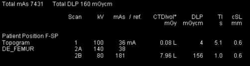
19 Knee kv 100 mas 94 1 mm 0,75 CTDIvol 5,93 DLP 90 RECON 2/2 kv 120 mas mm 0,75 CTDIvol 9,25 DLP 181

")

")


20 Paediatric 3y 100 Kv AEC ON 90mAs/110 16x0,75 (3mm) CTDIvol 22,5 DLP 380 2,5 y 80 Kv AEC Off 60mAs 16x0,75 (2mm) CTDIvol 1,85 DLP 14 2 y 100 Kv AEC On 25mAs/25 16x0,75 (2mm) CTDIvol 1,32 DLP 24 Images Courtesy : UMC Ljubljana

21 DRL Comparision Leta (l) Kv mas ref mas CTDIvol (mgy) DLP (mgycm) , , , , , , , , , , , , Povprečeje 6,85 210,6 DRL CT Pelvis in SI is 525 mgycm - 40% lower than DRL SI Lower ImQ only for 3D navigation
.")
 by user.")
22 Automatic kv selection Care kv Siemens kv Assist GE Crucial Localizer tissue attenuation (patient in isocenter!). Do we need one or two localizers (in different angle AP,LAT at 90 Δ). Defined noise (mas, Noise Index) by user. Suggested regarding clinical needs (MSK, Iodine, LCR-soft tissue). System adopt mas and kv to gain same image noise (ImQ).


23 Summarize The lower the tube voltage the higher the iodine contrast in the image because the average energy of the spectrum gets closer to the k-edge of iodine. In small patients, has almost no effect. Larger objects absorb a significant amount of low energy photons noise can rise dramatically For small patients the CNR increases when going to lower kv, for bigger patients it has a maximum and drops again when lowering the tube voltage. Ref:
24 Tube current -AEC Fixed or AEC. Fixed To avoid tube current manipulation. Paediatric very small patients below e.g. 10 kg. Size or indication specific (shoulder arthro..). AEC AEC standard vendor specific regarding x,y and z axis tube current modulation. Requires localizer (1 or 2). AEC change when slice thickness, pitch and kv (vendor specific). Do we understand how it works on our modality.


25 AEC well known facts AEC On 120 kv 125mAs/210 ref. mas 64x0,6 mm (1,5 mm) Pitch 0,6 Rot. time 0,5 s Scan time 9,57 s CTDI vol 9,03 mgy DLP 198,6 mgy*cm AEC ON AEC OFF 27 mas 165 mas AEC Off 120 kv 160mAs 64x0,6 mm (1,5 mm) Pitch 0,6 Rot. time 0,5 s Scan time 9,57 s CTDI vol 11,62 mgy DLP 255,6 mgy*cm 160 mas 160 mas
 DLP mgy*cm Detector 1.Very strong 100 104/160 8,47 123 64x0,6 2.")
26 AEC noise level Can be defined by user. Time to adopt or general use? Very strong Average Very weak Test Object 16 cm Cylindrical PMMA Type kv mas/ ref CTDIvol mgy (16 cm) DLP mgy*cm Detector 1.Very strong /160 8, x0,6 2. Average /160 9, x0,6 11% Advantages? Planned for different patient size 3.Very weak /160 11, x0,6 30%
 DLP 557 Scan lenght 43,9 cm Δ 38 % kv 120 mas 264/ ref 250 Collimation 64x1,2 Rot Time 0,5 s Slice thic.")
27 AEC - Noise or Ref mas Always same upper level of noise what about patient size kv 120 mas 190/ ref 180 Collimation 64x1,2 Rot Time 0,5 s Slice thic. 2mm CTDIvol 12,66 mgy (32 cm) DLP 557 Scan lenght 43,9 cm Δ 38 % kv 120 mas 264/ ref 250 Collimation 64x1,2 Rot Time 0,5 s Slice thic.2mm CTDIvol 17,53 mgy (32 cm) DLP 770 Scan lenght 43,9 cm


 Recon")
28 kv and AEC Art. Phase 100 Kv 114 mas/ ref 180 mas 64x0,6mm CTDIvol 4,84 mgy (32cm) Recon 1mm/0,7mm Recon 2mm/2mm MIP 7/5 - CM Venous phase 120 Kv 127 mas/ ref 140 mas 64x 1,2 mm CTDIvol 8,44 mgy (32cm) Recon 2mm/1mm Recon 2mm/2mm MIP 7/5 Vnous phase


29 CT Head trauma -4 m 1st AEC No 100 kv 380 mas CTDIvol 32,9 DLP cm AEC No 100 kv 190 mas CTDIvol 15,42 DLP cm Few h later
 120 kv AEC ON 125mAs/210 mas 64 X 0,6")


30 Detector configuration vs. dose and noise (AEC on) 120 kv AEC ON 125mAs/210 mas 64 X 0,6 mm Pitch 0,6 Rot time 0,5 s Scan time 9,57 s CTDIvol 9,03 mgy DLP 198,6 mgy*cm 1,5 mm 3 mm 5 mm 120 kv AEC ON 125mAs/210 mas 64 X 1,2 mm Pitch 0,6 Rot time 0,5 s Scan time 6,63 s CTDIvol 8,35 mgy DLP 190,4 mgy*cm 1,5 mm 3 mm 5 mm Tip size of the object, artefact reduction, noise -same

31 FOV according to the needs Small FOV allows increased spatial resolution until when? Pixel- inversely related to detail, smaller is better Matrix- directly related to detail, bigger is better directly FOV- inversely related to detail, smaller is better Pixel = FOV/ matrix FOV 500 mm Pixel 0,98 mm FOV 100 mm Pixel 0,20 mm Ref: E.Seeram, Computed Tomography: Physical Principles, Clinical Applications, and Quality


32 FOV noise FOV 300 mm Pixel size 0,6 mm FOV 260 mm Pixel size 0,5 mm FOV 164 Pixel size 0.32 mm Δ tissue


33 FOV- SR FOV 300 mm Pixel size 0,6 mm FOV 260 mm Pixel size 0,5 mm FOV 164 Pixel size 0.32 mm
34 Pitch Not so big factor in dose managements anymore. CT control the dose much better. u New scanners (check for your CT!) Siemens, Philips Δ Pitch leads to Δ ma (to get same nosie) Only speed with similar dose (paediatric, cardiac..) GE, Toshiba Some Δ ma when Δ pitch Higher pitch Lower dose (Scanning speed up) Lower pitch Higher dose (scanning speed down)
 DLP mgy x cm rot.")

35 Pitch-dose is changed (+AEC) Pitch 1 vs pitch 2 (50 % lower dose). TEST CAD 1 Kv mas/ref. CTDIvol(mGy) DLP mgy x cm rot. time c Sl mm Dosr L/S Pitch 0, /330 14, ,00 1,20 0% L/S Pitch 1, /330 14, ,00 1,20 6% L/S Pitch 1, /330 15, ,00 1,20 22% Example 16 slice CT Evaluate for your scanner! Pitch 0,8 Pitch 1,0 Pitch 1,5
 Δ Pitch Noise??")
36 Pitch dose is constant (+AEC) Δ Pitch Noise??


37 Pitch-dose is constant-3d Be careful some vendors are changing tube current to achieve constant ImQ. Then you will get only speed. Pitch 0,5 0,8 1,2 1,5 Pitch 0,5 0,8 1,2 1,5

 Type ( 0018,1160) : Flat Is the")

38 Bow tie filters Imege Courtesy : kv 200mAs AEC no Rot time 0,5 64x0,6 CTDIvol 11,47mGy (32cm) Type ( 0018,1160) : Wedge_2 120 kv 200mAs AEC no Rot time 0,5 64x0,6 CTDIvol 14,42mGy (32cm) Type ( 0018,1160) : Flat Is the scanner component that modifies the energy spectrum and spatial distribution of the primary beam. Affects CTDI vol. Inside organ program (difficult to see).


 DLP mgy*cm Detector?")

39 Rotation time CTDI vol may not change in the expected manner if the scanner automatically adjust other parameters when the exposure time per rotation is changed. The relationships between CTDIvol and exposure time per rotation is vendor dependant. 0,33 s 0,5 s 1 s Rotation Time Scan Time (s) kv mas/ ref CTDIvol mgy (32 cm) DLP mgy*cm Detector? 0,33 s 2, /275 17, x1,2 Δ aprox. 38% 0,5 s 3, /275 25, x1,2 Why? 1 s 6, /275 24, x1,2
40 Noise and slice thicknes 1 mm 2 mm 3 mm 5 mm Until when?


41 Reconstructed slice thickness 16 x 1,5 ; 2/1 recon 16 x 1,5 ; 3/3 recon 2/1 recon 3/3 recon 3/3 Image man. 2/1 Image man..


42 Reconstruction algorithms - Kernel Impact on : Noise/ Low Contrast Resolution Sapatial Resolution Important : Be aware of quality of diagnostic monitors - radiologist. Additional reconstruction is for free and takes 20 seconds


43 Play, explore 120 kv 166 mas 0,6 mm sl. Thic. /0,5 mm Increment Bone window Bone kernel 120 kv 166 mas 1mm sl. Thic. /1mm Increment Bone window Bone kernel 120 kv 166 mas 1mm sl. Thic. /1mm Increment Bone window Soft kernel 120 kv 166 mas 1mm sl. Thic. /1mm Increment Bone window Bone kernel 120 kv 166 mas 0,6 mm sl. Thic. /1mm Increment Bone window Soft kernel DLP 144 mgy*cm


44 Extented CT Values PigTitanum and Steel Soft window+ Extenced CT, Bone window 140 Kv 80 kv 80 mas 120 mas 0,6 mm 1,20 mm B 30f B70f Ref: A.Janežič, UMC LJ,SI


45 Dual Energy metal arifact MIP 3 mm/2 mm TRA 3MM/2MM VRT CTDIvol 7,99 DLP 160 mgycm SAG 3 mm/2 mm
46 Conclusion Explore your CT Use existing experience After acceptance test ask MP and Radiologist to get additional information Evaluate and optimise CT protocols Understanding the NOISE.

47 Thank you!
IAEA RER/9/135 COURSE ON OPTIMIZATION IN COMPUTED TOMOGRAPHY Sofia, Bulgaria, Tube current modulation and dose reduction : How TCM works
 IAEA RER/9/135 COURSE ON OPTIMIZATION IN COMPUTED TOMOGRAPHY Sofia, Bulgaria, 2017 Tube current modulation and dose reduction : How TCM works Dean Pekarovič UMC Ljubljana, Institute of Radiology Quality
Joint ICTP/IAEA Advanced School on Dosimetry in Diagnostic Radiology and its Clinical Implementation May 2009
 2033-17 Joint ICTP/ Advanced School on Dosimetry in Diagnostic Radiology and its Clinical Implementation 11-15 May 2009 Dosimetry for CT 3: Practical Experiences Claire-Louise Chapple Freeman Hospital
RSNA 2006 November 26 to December 1 Chicago. Guest author for ImPACT Dr. Koos Geleijns, Medical Physicist, Leiden University Medical Center.
 RSNA 2006 November 26 to December 1 Chicago Guest author for ImPACT Dr. Koos Geleijns, Medical Physicist, Leiden University Medical Center. Once again, more than 60,000 participants (including professional
2
 1 2 3 4 5 6 7 1. Bauhs, J. A., Vrieze, T. J., Primak, A. N., Bruesewitz, M. R., & McCollough, C. H. (2008). CT Dosimetry: Comparison of Measurement Techniques and Devices1. Radiographics, 28(1), 245-253.
Iterative Reconstruction with Philips idose Characterising Image Quality in Attempting to Realise its Potential
 Iterative Reconstruction with Philips idose Characterising Image Quality in Attempting to Realise its Potential Julie Smyth & Philip Doyle Regional Medical Physics Service Outline Preamble Image Quality
Standard. Substitute Test or Procedure. Required Test or. 1 Scan Increment Accuracy. Initially and Annually Initially and Annually
 Manufacturer s Recommendations for Alternate Dental CBCT QA Program VaTech: Model PAX i3d, i3d Green, i3d Smart Table 6 Medical Physicist s Computed Tomography QC Survey Required Test or Item Procedure
Comparison of Measured Values of CTDI and DPL with Standard Reference values of Different CT Scanners for dose Management
 2017 IJSRST Volume 3 Issue 1 Print ISSN: 2395-6011 Online ISSN: 2395-602X Themed Section: Science and Technology Comparison of Measured Values of CTDI and DPL with Standard Reference values of Different
A simple anthropomorphic phantom used to demonstrate the effectiveness of CT dose modulation functions.
 A simple anthropomorphic phantom used to demonstrate the effectiveness of CT dose modulation functions. Lynn Bateman & Peter Hiles North Wales Medical Physics How can we test CT dose modulation? Lynn Bateman
Equipment Quality Control for Digital Radiography February 22, Imaging Physics CancerCare Manitoba
 Equipment Quality Control for Digital Radiography February 22, 2018 Imaging Physics CancerCare Manitoba Purpose An equipment quality control (QC) program establishes baseline performance levels, tracks
In recent years, CT technology has undergone profound
 PATIENT SAFETY Y.T. Niu M.E. Olszewski Y.X. Zhang Y.F. Liu J.F. Xian Z.C. Wang Experimental Study and Optimization of Scan Parameters That Influence Radiation Dose in Temporal Bone High-Resolution Multidetector
NEMA XR 25 COMPUTED TOMOGRAPHY DOSE CHECK
 NEMA XR 25 COMPUTED TOMOGRAPHY DOSE CHECK NEMA Standards Publication XR 25-2010 Computed Tomography Dose Check Published by: National Electrical Manufacturers Association 1300 North 17th Street, Suite
Madero Ote. 686, Centro Histórico, C.P Morelia, Michoacán México. #300, Col. Cuauhtémoc, C.P Morelia, Michoacán, México
 Verification of and DLP values for a head tomography reported by the manufacturers of the CT scanners, using a CT dose profiler probe, a head phantom and a piranha electrometer Edith Castillo Corona 1,2,
Ride the Lightning. A Review of Radiographic Physics
 Ride the Lightning A Review of Radiographic Physics Overview Basic principles of x-ray production Imaging equipment Quality Control Technical Factors Image QA Preparing for the registry The ARRT just wants
What do we mean by workload? Number of scans Type of scans/mix of scans? Total mas Total dip
 CT & Workload (BIR) David Sutton What do we mean by workload? Number of scans Type of scans/mix of scans? Total mas Total dip What do we do with it? Need to relate workload to total scatter dose in the
A method for calculating the dose length product from CT DICOM images
 The British Journal of Radiology, 84 (2011), 236 243 A method for calculating the dose length product from CT DICOM images 1 I A TSALAFOUTAS, PhD and 2 S I METALLIDIS, MSc 1 Medical Physics Department,
2012 Computed Tomography
 2012 Computed Tomography QUALITY CONTROL MANUAL Radiologist s Section Radiologic Technologist s Section Medical Physicist s Section 2012 Computed Tomography QUALITY CONTROL MANUAL Radiologist s Section
QUALITY CONTROL AND PATIENT DOSES FROM X-RAY EXAMINATIONS IN SOME HOSPITALS IN THAILAND
 QUALITY CONTROL AND PATIENT DOSES FROM X-RAY EXAMINATIONS IN SOME HOSPITALS IN THAILAND P. Plainoi, W. Diswath, N. Manatrakul Ministry of Public Health, Nonthaburi, Thailand XA0101612 Abstract Quality
2017 Computed Tomography
 2017 Computed Tomography QUALITY CONTROL MANUAL Radiologist s Section Radiologic Technologist s Section Qualified Medical Physicist s Section 2017 Computed Tomography QUALITY CONTROL MANUAL Radiologist
Scope: All CT staff technologist
 APPROVED BY: Radiology Technical Director Page 1 of 6 Purpose: The QC program assesses relative changes in system performance as determined by the technologist, service engineer, qualified medical physicist,
Brilliance CT 64-channel configuration
 Brilliance CT 64-channel configuration with Essence technology The Brilliance CT 64-channel configuration is designed to help you conduct the most advanced multislice CT studies possible. These systems
Request for Proposals
 Request for Proposals Reference: ERDFIAI2012-4006A Caring First Ltd, is a limited liability company providing healthcare services. The company is currently commissioning a private new-build hospital complete
Staff dose and good prac/ces in CT guided IR procedures. Jonas Andersson Medical Physicist, Ph.D.
 Staff dose and good prac/ces in CT guided IR procedures Jonas Andersson Medical Physicist, Ph.D. jonas.s.andersson@vll.se Contents Good prac/ces for staff dose management Staff dose reported in the literature
Case 1 8/1/2017. Ring Artifact? James M. Kofler, Ph.D. Mayo Clinic Rochester. AAPM Annual Meeting TU-B Artifacts: CT 2
 James M. Kofler, Ph.D. Mayo Clinic Rochester AAPM Annual Meeting 2017 1 Case 1 Ring Artifact? 2 3 1 Star Pattern caused by metal earrings! 4 Same star artifact commonly caused by Dental Amalgam Metal Implants
CT Numbers: Think of a number, double it, add 20, divide by 4. Jane Edwards Royal Free Hospital, London
 CT Numbers: Think of a number, double it, add 20, divide by 4 Jane Edwards Royal Free Hospital, London Background 2 different manufacturers CT scanners available on site: GE Lightspeed Plus; Philips Brilliance
FFDM Quality Control in Canada - a Vendor Neutral Approach
 FFDM Quality Control in Canada - a Vendor Neutral Approach Rasika Rajapakshe, PhD, FCCPM BC Cancer Agency-Center for the Southern Interior Kelowna, BC, Canada 2011 Joint AAPM/COMP Meeting August 4, 2011
Department of Medical Physics, Graduate School of Nuclear and Allied Science, University of Ghana, Accra - Ghana, West Africa
 2018 IJSRST Volume 4 Issue 5 Print ISSN: 2395-6011 Online ISSN: 2395-602X Themed Section: Science and Technology Assessment of Adult Patient Radiation Dose and Image Quality in CT Examinations Performed
MSK Imaging Fundamentals
 MSK Imaging Fundamentals Goals Improve image quality Provide best possible product for our customers Patient Referring clinician Radiologist Reduce number of callback cases Goal reduction of 50% in 3 months
FDA MAMMOSCAN FULL FIELD DIGITAL MAMMOGRAPHY SYSTEM MAMMOGRAPHY
 MAMMOGRAPHY MAMMOSCAN FULL FIELD DIGITAL MAMMOGRAPHY SYSTEM Biopsy Attachment џ MAMMOSCAN is a digital scanning technology development taking a special place in ADANI Medical X-ray product line. џ Its
Collimation and Light Field Brightness
 Collimation and Light Field Brightness Physics and Reasoning Principle 1: Primary X Ray beam is blocked by breast support table. Principle 2: Need to properly imageas as much breast tissue as possible.
More Info at Open Access Database Process Control for Computed Tomography using Digital Detector Arrays
 Digital Industrial Radiology and Computed Tomography (DIR 2015) 22-25 June 2015, Belgium, Ghent - www.ndt.net/app.dir2015 More Info at Open Access Database www.ndt.net/?id=18082 Process Control for Computed
Built to do More. Brivo CT slice CT product data sheet
 GE Healthcare Built to do More. Brivo CT385 16-slice CT product data sheet Built for your Confidence. BIG Performance, small footprint Smart CT Desk Energy Saving Mode Simply Advance Hilight Scintillator
True comfort and flexibility with the power of 3T.
 True comfort and flexibility with the power of 3T. With a large 71 cm aperture and the quietest exams in the industry, the Vantage Titan 3T is the most comfortable 3T MRI system for all of your patients.
Precision, power, and productivity
 Precision, power, and productivity Philips Brilliance CT Big Bore oncology configuration Philips Healthcare continues its tradition of innovation in oncology with a CT solution that specifically addresses
Abstract. Learning Objectives 8/1/2017
 SAM Practical Medical Physics TU-B-201-0 AAPM Annual Meeting 2017 1 Abstract This course will teach the participant to identify common artifacts found clinically in MR, DR, CT, PET, to determine the causes
Practix. Mobile Radiography. All a Bucky station needs plus mobility. Practix 400
 Practix 400 Specifications Practix Mobile Radiography All a Bucky station needs plus mobility Practix 400 Practix 400 meets the most demanding requirements of medical care, combining the virtues of mobile
4/14/2009. The Big Picture of Quality. MRI Quality Assurance and ACR MRI Accreditation Program. Basic Elements for Image Quality.
 The Big Picture of Quality MRI Quality Assurance and ACR MRI Accreditation Program Chen Lin, PhD Indiana University School of Medicine & Clarian Health Partners Diagnosis accuracy Image quality Knowledge
Performance Evaluation of Industrial Computed Radiography Image Display System
 Performance Evaluation of Industrial Computed Radiography Image Display System More info about this article: http://www.ndt.net/?id=21169 Lakshminarayana Yenumula *, Rajesh V Acharya, Umesh Kumar, and
CHAPTER 4: HIGH ENERGY X-RAY GENERATORS: LINEAR ACCELERATORS. Jason Matney, MS, PhD
 CHAPTER 4: HIGH ENERGY X-RAY GENERATORS: LINEAR ACCELERATORS Jason Matney, MS, PhD Objectives Medical electron linear accelerators (often shortened to LINAC) The Basics Power Supply Magnetron/Klystron
Imaging diagnostico in Sanità Stato attuale e prospettive
 Imaging diagnostico in Sanità Stato attuale e prospettive Sandro Paini AMI & Oncology Pisa 20.12.2016 Fully digital SiPM (dsipm ) invented within Philips Research PMT APD(analog) SiPM(Analog) dsipm( Digital)
UArm. Series. Analog or Digital U-Arm System
 UArm Analog or Digital U-Arm System Series A world class direct digital imaging system with positioning flexibility and ease of use for all procedures. Eighty Years of Excellence UArm Series POSITIONING
Optima CT660 Optima CT660
 Product Data Sheet Rev 2 Page 1/18 Optima CT660 Optima CT660 Milwaukee, USA - Fax: 1 262 544 3384 Tokyo, Japan - Fax: 81 425 85 5490 Paris, France - Fax: 33 1 30 70 94 35 Optima TM CT660 Product Description
High Frequency X-Ray Technology. Wide Screen Control with Touch-Technology
 High Frequency X-Ray Technology Wide Screen Control with Touch-Technology The Q-VISION HF Series TM The Q-VISION Series TM integrates innovative high frequency design along with superb functionality, resulting
Promises and Perils of Proton Therapy Beam Delivery (Implications) or Towards Cost Effective Particle Therapy
 or Towards Cost Effective Particle Therapy") Promises and Perils of Proton Therapy Beam Delivery (Implications) or Towards Cost Effective Particle Therapy Jay Flanz MGH/FBTC Harvard Medical School What is a Beam Delivery? Start with an accelerator
Promises and Perils of Proton Therapy Beam Delivery (Implications) or Towards Cost Effective Particle Therapy Jay Flanz MGH/FBTC Harvard Medical School What is a Beam Delivery? Start with an accelerator
YXLON Cougar EVO PLUS
 YXLON Cougar EVO PLUS The best small footprint X-ray inspection system for LABORATORY applications Technology with Passion Choose a custom-built EVO solution for premium inspection Why compromise? As technology
Technologist Quality Control Procedures
 Technologist Quality Control Procedures The specific procedures for the Technologist Quality Control Program are those specified in the most current ACR MRI QC Manual. WEEKLY MRI EQUIPMENT QUALITY CONTROL
Creating room. for your visions
 BuckyDiagnost Radiography solutions Creating room for your visions 2 What makes a Rad Room simply perfect? Room for all your ideas Efficient, powerful, individual and innovative. This sums up just some
World First Slim Cassette Type Digital Mammo. Upgrade Solution
 World First Slim Cassette Type Digital Mammo. Upgrade Solution Still Analog? Slim Cassette Type Digital Mammo. Upgrade Solution Contents 3 P. 5 P. 7 P. 9 P. 11 P. 13 P. 1824C & 2430C, easy digitalization
MR Accreditation Programs - E. Jackson
 MRI Accreditation Programs: An Overview of Each and Specifics of One Edward F. Jackson, PhD Department of Imaging Physics 1 Diagnostic - MRI Safety and Accreditation Educational Objectives At the conclusion
Mechanical aspects, FEA validation and geometry optimization
 RF Fingers for the new ESRF-EBS EBS storage ring The ESRF-EBS storage ring features new vacuum chamber profiles with reduced aperture. RF fingers are a key component to ensure good vacuum conditions and
+ Human method is pattern recognition based upon multiple exposure to known samples.
 Main content + Segmentation + Computer-aided detection + Data compression + Image facilities design + Human method is pattern recognition based upon multiple exposure to known samples. + We build up mental
LightSpeed 16 With Xtream CT Scanner System
 Page 1 Introduction The CT Scanner with Xtream TM technology is the next step in GE s CT Continuum and its awardwinning LightSpeed CT platform. The CT Scanner routinely acquires 16 sub-millimeter slices
Ergonomic design packed with powerful performance MULTIMOBIL 5C. Answers for life.
 Ergonomic design packed with powerful performance MULTIMOBIL 5C Answers for life. MULTIMOBIL 5C Mobile C-arm image intensifier system with high frequency technology Siemens has led the way in development
Laser Beam Analyser Laser Diagnos c System. If you can measure it, you can control it!
 Laser Beam Analyser Laser Diagnos c System If you can measure it, you can control it! Introduc on to Laser Beam Analysis In industrial -, medical - and laboratory applications using CO 2 and YAG lasers,
This talk covers currently available display technology.
 Introduction to Current Display Technologies for Medical Image Viewing Perspectives for the TG270 Update on Display Quality Control Alisa Walz-Flannigan, PhD (DABR) Mayo Clinic, Rochester, Minnesota AAPM
Selection Criteria for X-ray Inspection Systems for BGA and CSP Solder Joint Analysis
 Presented at Nepcon Shanghai 2003 Abstract Selection Criteria for X-ray Inspection Systems for BGA and CSP Solder Joint Analysis Dr. David Bernard, Dage Precision Industries, 158-29 Hua Shan Road, Feng
Essentials of Digital Imaging
 Essentials of Digital Imaging Module 3 Transcript 2016 ASRT. All rights reserved. Essentials of Digital Imaging Module 3 Display 1. ASRT Animation 2. Welcome Welcome to the Essentials of Digital Imaging
Biograph Vision See a whole new world of precision
 Biograph Vision See a whole new world of precision and its national implementations and are not yet commercially available in the European Union. Unrestricted Unrestricted Siemens Healthcare Siemens Healthcare
Breast Imaging Essentials
 Breast Imaging Essentials Module 10 Transcript 2016 ASRT. All rights reserved. Breast Imaging Essentials Module 10 Digital Breast Tomosynthesis 1. ASRT Animation 2. Welcome Welcome to Module 10 of Breast
-Technical Specifications-
 Annex I to Contract 108733 NL-Petten: the delivery, installation, warranty and maintenance of one (1) X-ray computed tomography system at the JRC-IET -Technical Specifications- INTRODUCTION In the 7th
3/2/2016. Medical Display Performance and Evaluation. Objectives. Outline
 Medical Display Performance and Evaluation Mike Silosky, MS University of Colorado, School of Medicine Dept. of Radiology 1 Objectives Review display function, QA metrics, procedures, and guidance provided
Intra-oral X-ray unit with high frequency DC generator. Product Data
 Intra-oral X-ray unit with high frequency DC generator Tubehead Features Product Data High voltage circuit type High frequency (DC) High voltage frequency 30 khz Rated output voltage 60-65 - 70 kvp ± 8%
Vascular. Development of Trinias FPD-Equipped Angiography System. 1. Introduction. MEDICAL NOW No.73 (2013.2) Yoshiaki Miura
 Yoshiaki Miura") Vascular Development of Trinias FPD-Equipped Angiography System Medical Systems Division, Shimadzu Corporation Yoshiaki Miura 1. Introduction Shimadzu has developed Trinias (one ceiling-mounted type C12
Vascular Development of Trinias FPD-Equipped Angiography System Medical Systems Division, Shimadzu Corporation Yoshiaki Miura 1. Introduction Shimadzu has developed Trinias (one ceiling-mounted type C12
Introduction. Edge Enhancement (SEE( Advantages of Scalable SEE) Lijun Yin. Scalable Enhancement and Optimization. Case Study:
 Lijun Yin. Scalable Enhancement and Optimization. Case Study:") Case Study: Scalable Edge Enhancement Introduction Edge enhancement is a post processing for displaying radiologic images on the monitor to achieve as good visual quality as the film printing does. Edges
Case Study: Scalable Edge Enhancement Introduction Edge enhancement is a post processing for displaying radiologic images on the monitor to achieve as good visual quality as the film printing does. Edges
Assessment of the Impact of Dark Signal on Image Quality in Computerized Mammography. Introduction
 Assessment of the Impact of Dark Signal on Image Quality in Computerized Mammography Alexia Valasi 1, Maria Argyrou 1, Ioannis Floros 1, Elisavet Molyvda 2, Anastasios Siountas 2, Stella Synefia 1, Ioannis
Drift Tubes as Muon Detectors for ILC
 Drift Tubes as Muon Detectors for ILC Dmitri Denisov Fermilab Major specifications for muon detectors D0 muon system tracking detectors Advantages and disadvantages of drift chambers as muon detectors
Operating Procedures for RECO1 & RECO2
 Operating Procedures for RECO1 & RECO2 Reconstruction of Data 1) Open CT Pro 3D a. Remember, when the computer you are working on is receiving files from the scanner, it cannot reconstruct data b. You
Screen investigations for low energetic electron beams at PITZ
 1 Screen investigations for low energetic electron beams at PITZ S. Rimjaem, J. Bähr, H.J. Grabosch, M. Groß Contents Review of PITZ setup Screens and beam profile monitors at PITZ Test results Summary
Guidelines for Quality Assurance in Radiation Protection for Diagnostic X-Ray Facilities: Large X-Ray Facilities
 Guidelines for Quality Assurance in Radiation Protection for Diagnostic X-Ray Facilities: Large X-Ray Facilities J L Poletti 1995/1 NRL Report GUIDELINES FOR QUALITY ASSURANCE IN RADIATION PROTECTION FOR
CARESTREAM VITA/VITA LE/VITA SE CR System Long Length Imaging User Guide
 CARESTREAM VITA/VITA LE/VITA SE CR System Long Length Imaging User Guide Use of the Guide Carestream CR Systems are designed to meet international safety and performance standards. Personnel operating
Impact of DMD-SLMs errors on reconstructed Fourier holograms quality
 Journal of Physics: Conference Series PAPER OPEN ACCESS Impact of DMD-SLMs errors on reconstructed Fourier holograms quality To cite this article: D Yu Molodtsov et al 2016 J. Phys.: Conf. Ser. 737 012074
Non-Destructive Examination Benches and Analysis Laboratories in support to the Experimental Irradiation Process in the Future Jules Horowitz MTR
 Non-Destructive Examination Benches and Analysis Laboratories in support to the Experimental Irradiation Process in the Future Jules Horowitz MTR D. Parrat 1, P. Kotiluoto 2, T. Jäppinen 2, C. Roure 1,
Quality Assurance Implementation at the Roberts Proton Therapy Center. James McDonough 3 August 2013
 Quality Assurance Implementation at the Roberts Proton Therapy Center James McDonough 3 August 2013 1 Roberts Proton Therapy Center Machine configuration and layout 4 gantries, 1 fixed beam line, 1 research
Overview. ACR Accreditation Update in Mammography. ACR Topics. Requirements Today. What s Coming For Tomorrow
 ACR Accreditation Update in Mammography Eric Berns, PhD University of Colorado Hospital Denver Health Medical Center Denver, CO *No financial disclosures to report Overview ACR Topics Requirements Today
BEAMAGE 3.0 KEY FEATURES BEAM DIAGNOSTICS PRELIMINARY AVAILABLE MODEL MAIN FUNCTIONS. CMOS Beam Profiling Camera
 PRELIMINARY POWER DETECTORS ENERGY DETECTORS MONITORS SPECIAL PRODUCTS OEM DETECTORS THZ DETECTORS PHOTO DETECTORS HIGH POWER DETECTORS CMOS Beam Profiling Camera AVAILABLE MODEL Beamage 3.0 (⅔ in CMOS
The Black Piranha Easy & Fast X-ray Quality Control
 From Radiation to Information The Black Piranha Easy & Fast X-ray Quality Control The Black Piranha with accessories makes X-ray QA easy and fast. Connection is automatic just plug n play. The Quick Check
Spectroscopy on Thick HgI 2 Detectors: A Comparison Between Planar and Pixelated Electrodes
 1220 IEEE TRANSACTIONS ON NUCLEAR SCIENCE, OL. 50, NO. 4, AUGUST 2003 Spectroscopy on Thick HgI 2 Detectors: A Comparison Between Planar and Pixelated Electrodes James E. Baciak, Student Member, IEEE,
Corrigendum-II. Up to 30 th October 2018 till 17:00 Hrs. 31 st October 2018 till 17:00 Hrs. 2 nd November 2018 till 14:00 Hrs.
 Bihar Medical Services & Infrastructure Corporation Limited 4 th floor State Building Construction Corporation Limited. Hospital Road, Shastri Nagar, Patna 800023, Phone/Fax: +91612 2283287,+ 91612 2283288
BCA 9S. ELECTRICAL CHARACTERISTICS Voltage 230 Vac ±10% monophase standard 105 / 115 / 125 / 220 / 240 Vac ±10% monophase on request
 ELECTRICAL CHARACTERISTICS Voltage 230 Vac ±10% monophase standard 105 / 115 / 125 / 220 / 240 Vac ±10% monophase on request Frequency 50 Hz standard 60 Hz on request Absorbed current on Stationary 4.5
SEAMLESS INTEGRATION MULTIPLE SOLUTIONS ONE PRODUCT ONE COMPANY
 SEAMLESS INTEGRATION ONE COMPANY ONE PRODUCT MULTIPLE SOLUTIONS SEAMLESS INTEGRATION ONE COMPANY - ONE PRODUCT - MULTIPLE SOLUTIONS Introduction As leaders in X-Ray Generator Technology we are utilizing
X-ray Tube Housing Assembly H1076X H1076Y Print No.HA Release Date:
 H1076X 0.6 1.5 H1076Y 0.6 1.5 Print No.HA1006 1 Release Date: 2013 07 15 Description X-ray Tube Housing Assembly The tube unit is so constructed that an X-ray tube is sealed in a diagnostic type protective
Procedure Manual for MRI of the Brain
 Baxter Protocol 161003 SYN RC W H E R E S C I E N C E M E E T S S E R V I C E Baxter Protocol 161003 A Phase 3 Randomized, Double-Blind, Placebo-Controlled Study of the Safety and Effectiveness of Immune
Automatic Defect Recognition in Industrial Applications
 Automatic Defect Recognition in Industrial Applications Klaus Bavendiek, Frank Herold, Uwe Heike YXLON International, Hamburg, Germany INDE 2007 YXLON. The reason why 1 Different Fields for Usage of ADR
Standard Operating Procedure of nanoir2-s
 Standard Operating Procedure of nanoir2-s The Anasys nanoir2 system is the AFM-based nanoscale infrared (IR) spectrometer, which has a patented technique based on photothermal induced resonance (PTIR),
JEFFERSON COLLEGE. Image Intensification & Equipment
 JEFFERSON COLLEGE COURSE SYLLABUS RAD175 Image Intensification & Equipment 3 Credit Hours Revised by: Janet E. Akers BS RT (R)(M) Date: October 3, 2013 Kenny Wilson, Director, Health Occupation Programs
Imaging solutions for any size patient and any size budget.
 Imaging solutions for any size patient and any size budget. VetTek V e t e r i n a r y X - R a y S y s t e m s VetTek We See Things Differently & It Shows In Your Image Imagine a veterinary x-ray system
using the Scott A Speakman, Ph.D Center for Materials Science and Engineering at MIT
 X-Ray Reflectivity using the PANalytical X Pert Pro MPD Scott A Speakman, Ph.D Center for Materials Science and Engineering at MIT http://prism.mit.edu/xray Modified for configuration used at University
Linatron - M9 & M9A. Modular high-energy X-ray source. 2.0 Performance
 The Linatron -M is a modular system. The control console, modulator, and RF unit are common to all model configurations. Only the X-ray head changes to match the application. The Linatron - M is designed
Low-Energy Electron Linacs and Their Applications in Cargo Inspection
 Low-Energy Electron Linacs and Their Applications in Cargo Inspection Yawei Yang on behalf of Huaibi Chen *,1, Chuanxiang Tang 1 Yaohong Liu 2 *chenhb@tsinghua.edu.cn 1 Department of Engineering Physics,
BCA 9R. 60 Hz on request Absorbed current on Stationary Vac and Vac in fluoro mode
 ELECTRICAL CHARACTERISTICS RADIOLOGICAL DATA MONOBLOC Voltage 230 Vac ±10% monophase standard 105 / 115 / 125 / 220 / 240 Vac ±10% monophase on request Frequency 50 Hz standard 60 Hz on request Absorbed
Comed Medical Systems Co., Ltd. Office 707, Woolim Lion s Valley I, 311-3, Sangdaewon-dong, Seongnam-si, Gyeonggi-do, Korea Tel:
 Comed Medical Systems Co., Ltd. Office 707, Woolim Lion s Valley I, 311-3, Sangdaewon-dong, Seongnam-si, Gyeonggi-do, Korea Tel:+82-31-737-2211 Fax:+82-31-737-2210 Factory 236-4 Sangdaewon-dong, Seongnam-si,
Financial disclosure statement. Fluoroscopic Equipment Design: What s s Different with Flat Panel? Concept of flat panel imager
 Fluoroscopic Equipment Design: What s s Different with Flat Panel? John Rowlands Financial disclosure statement Research supported by Anrad Corp Anrad Corp is a manufacturers of selenium based flat panel
Implementing a Proton Beam Scanning System within an Operating Clinical Facility
 Implementing a Proton Beam Scanning System within an Operating Clinical Facility Ben Clasie Many thanks to Hassan Bentefour, Hanne Kooy, and Jay Flanz for their help preparing this presentation 1 Francis
Requirements for Imaging
 Requirements for Imaging Max Seidensticker Universitätsklinikum Magdeburg Klinik für Radiologie & Nuklearmedizin SORAMIC 1 Requirements for Imaging SORAMIC: Evaluation of Sorafenib and microtherapy guided
Y.XST225-VF. INTERCONTROLE Escoffier 1 XYLON MG225VF RX PDS
 Y.XST225-VF 1 XYLON MG225VF - 0509- RX0905007PDS 1 Table of contents Y.XST225-VF High detail visibility - examples Y.XST225-VF vs. conventional X-ray systems Y.XST225-VF vs. µ-focus X-ray systems Unique
X-Ray Machines, CT Scanners, MRIs: The Pivotal Role of the GE Research and Development Center
 CT Scanner Protoype at UCSF Medical Center 1976 X-Ray Machines, CT Scanners, MRIs: The Pivotal Role of the GE Research and Development Center by Walter L. Robb Early Years In 1895, Professor Wilhelm Conrad
CARESTREAM DIRECTVIEW Elite CR System
 CARESTREAM DIRECTVIEW Elite CR System Improve workflow, productivity, and patient throughput. The CARESTREAM DIRECTVIEW Elite CR System is small, easy to install and easy to use. This powerful distributed
CARESTREAM DIRECTVIEW Elite CR System
 CARESTREAM DIRECTVIEW Elite CR System Improve workflow, productivity, and patient throughput. The CARESTREAM DIRECTVIEW Elite CR System is small, easy to install and easy to use. This powerful distributed
SciFi A Large Scintillating Fibre Tracker for LHCb
 SciFi A Large Scintillating Fibre Tracker for LHCb Roman Greim on behalf of the LHCb-SciFi-Collaboration 14th Topical Seminar on Innovative Particle Radiation Detectors, Siena 5th October 2016 I. Physikalisches
A new shielding calculation method for X-ray computed tomography regarding scattered radiation
 Radiol Phys Technol (2017) 10:213 226 DOI 10.1007/s12194-016-0387-9 A new shielding calculation method for X-ray computed tomography regarding scattered radiation Hiroshi Watanabe 1,2 Kimiya Noto 3 Tomokazu
Display Quality Assurance: Recommendations from AAPM TG270 for Tests, Tools, Patterns, and Performance Criteria
 Display Quality Assurance: Recommendations from AAPM TG270 for Tests, Tools, Patterns, and Performance Criteria Nicholas B. Bevins, Ph.D. TG270 Co-chair Display Check 2 1 TG270 Goals Provide an update