Manual Central Panel MIP B737 IDC. Date:12/18/14 Rev.:1.0
|
|
|
- Meredith McBride
- 5 years ago
- Views:
Transcription


1 Manual Central Panel MIP B77 IDC. Date:/8/ Rev.:.0
2 Manual Central Panel MIP B77 IDC Index: MANUAL CENTRAL PANEL MIP B77 IDC... INDEX:... INTRODUCTION:... BKI TECHNOLOGY:... WIRING DIAGRAM:... CONNECTOR'S DESCRIPTION:... Connection of Auto Brake and Flaps indicators to central panel:... INPUTS AND OUTPUTS DECLARATION:... 5 LINKS DE INTERÉS:... ERROR! MARCADOR NO DEFINIDO. ANEXE:

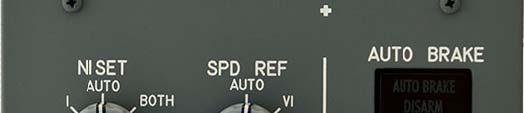
3 Manual Central Panel MIP B77 IDC Introduction: B77 MIP central panel, flaps 5º, with IDC connection and with integrated backlight technology BKI panel. Made from a 6mm thick piece, with painted finish and professional engraving. This panel was desigend to connect with inputs and outputs cards like IOCARD MIP, Master plus Expansion or other. The panel has the following operating elements: Rotary switches and encoders and momentary switch. MFD keys. Autobrake indicator. Backlight. As a novelty we introduce two concentric rotary encoders switches for full functionality of the panel and outputs (5V) for external panel indicators (Anti Skid Inop, LE Flaps Transit and LE Flaps Extended). BKI Technology: The BKI technology is similar to the original used in the original Boeing panels, it is embedded within the backlight panels, increasing the quality of the backlight and a significant drop in energy consumption and to avoid light pollution around the panels. Wiring diagram: Central panel can be connected to any inputs and outputs card through 0 pins IDC connector. SEE ANEXE. Connector's Description: The central panel put into service with the following connections. J9 CONNECTOR 0 PINS I/O PIN FUNCTION I/O PIN FUNCTION GND GND OUTPUTS I SPD REF ROTARY "<" O INDICATOR (5V INCLUDED) I5 SPD REF ROTARY "SET" O INDICATOR (5V) I6 SPD ENCODER O INDICATOR (5V) I7 SPD ENCODER BIS O 5 INDICATOR (5V) GNDG 5 GND INPUTS I I8 6 AUTOBRAKE ROTARY "RTO" I 7 N SET ROTARY "" I9 7 AUTOBRAKE ROTARY "OFF" I 8 N SET ROTARY "" I0 8 AUTOBRAKE ROTARY "" I 9 N SET ROTARY "AUTO" I 9 AUTOBRAKE ROTARY "" I 0 N SET ROTARY "BOTH" I 0 AUTOBRAKE ROTARY "" I5 N SET ENCODER I AUTOBRAKE ROTARY "MAX" I6 N SET ENCODER BIS I MFD BUTTON "ENG" I7 FUEL FLOW "USED" I5 MFD BUTTON "SYS" I8 FUEL FLOW "RESET" GNDP GND BACKLIGHT

4 GNDG 5 GND INPUTS I-8 PWLED 5 I9 6 - GNDP 6 I0 7 SPD REF ROTARY "AUTO" PWLED 7 Manual Central Panel MIP B77 IDC POSITIVE BACKLIGHT. Power feeding from. volts to.9 volts Attention: more voltage may damage the backlight! GND BACKLIGHT MFD BUTTONS POSITIVE BACKLIGHT MFD BUTTONS Power feeding from. volts to.9 volts. I 8 SPD REF ROTARY "V" I 9 SPD REF ROTARY "VR" GNDG 9 GND INPUTS I8-I5 I 0 SPD REF ROTARY "WT" J & J5 CONNECTORS: OUTPUTS INDICATORS PANEL (pcb connectors) I/O PIN FUNCTION I/O PIN FUNCTION POSITIVE O (5V USED) POSITIVE O (5V) J POSITIVE O (5V) J5 GND OUTPUTS POSITIVE O (5V) GND OUTPUTS (USED) USB Dimcontrol card is recommended to manage the backlight. Connection of Auto Brake and Flaps indicators to central panel: The Auto Brake Disarm indicator comes wired and operative from factory, but other indicators can be connected to the central panel (Anti Skid Inop, LE Flaps Transit and LE Flaps Extended). They can be connected to any inputs or outputs card directly or wired to the Central Panel. There are two ways.. The positive pins (pin ) of each indicator goes to their respective panel outputs (O, O, O & O): J pin (O) wired to Auto Brake Disarm pin, J pin (O) to Anti Skid Inop pin, J pin (O) to LE Flaps Transit pin and J5 pin (O) to LE Flaps Ext pin and negative pins (GNDs): from J5 pin to Auto Brake Disarm pin, from Auto Brake Disarm pin exits a jumper to Anti Skid Inop pin (GND), from Anti Skid Inop pin (GND) exits other jumper to LE Flaps Transit pin (GND) and from LE Flaps Transit pin exits other jumper to LE Flaps Ext pin. J5 O GND GND J O O O LE FLAPS EXT LE FLAPS TRANSIT ANTI SKID INOP AUTO BRAKE DISARM
5 Manual Central Panel MIP B77 IDC. The positives are connected the same way: The positive pins (pin ) of each indicator goes to their respective panel outputs (O, O, O & O): J pin (O) wired to Auto Brake Disarm pin, J pin (O) to Anti Skid Inop pin, J pin (O) to LE Flaps Transit pin and J5 pin (O) to LE Flaps Ext pin and negative for Auto Brake Disarm indicator like factory wiring and for other indicators: from J5 pin (GND) exits a wire to Anti Skid Inop pin (GND), from Anti Skid Inop pin (GND) exits other jumper to LE Flaps Transit pin (GND) and from LE Flaps Transit pin exits other jumper to LE Flaps Ext pin. J5 O GND GND J O O O LE FLAPS EXT LE FLAPS TRANSIT ANTI SKID INOP AUTO BRAKE DISARM Inputs and Outputs Declaration: To declare variables of inputs and outputs the previous table of connection must be used. The numbers assigned will depend of wiring and inputs and outputs cards used. If we use a Master Expansion card with or without the IOCard MIP PCB the inputs and outputs are static, but other cards can be used too. With the IOCard MIP PCB and Master Expansion cards the inputs and outputs will be the same and the official OC scripts and custom scripts will be the same too. Inputs and outputs definition: // OUTPUTS Var 000, name MIPBRAKEDIS_O, Link IOCARD_OUT, DEVICE XX, Output // AUTO BRAKE DISARM INDICATOR Var 00, name MIPANTI_SKID_O, Link IOCARD_OUT, DEVICE XX, Output // ANTI SKID INOP INDICATOR Var 00, name MIPFLAPTRANS_O, Link IOCARD_OUT, DEVICE XX, Output // LE FLAPS TRANSIT INDICATOR Var 006, name MIPFLAPSEXT_O, Link IOCARD_OUT, DEVICE XX, Output // LE FLAPS EXTENDED INDICATOR // INPUTS // N SET Var 00, name NSET_I, Link IOCARD_SW, DEVICE XX, Input 6 // N SET ROTARY SWITCH POSITION Var 0, name NSET_I, Link IOCARD_SW, DEVICE XX, Input 7 // N SET ROTARY SWITCH POSITION Var 0, name NSETAUTO_I, Link IOCARD_SW, DEVICE XX, Input 8 // N SET ROTARY SWITCH POSITION AUTO Var 06, name NSETBOTH_I, Link IOCARD_SW, DEVICE XX, Input 9 // N SET ROTARY SWITCH POSITION BOTH Var 08, name NSETENC_I, Link IOCARD_SW, DEVICE XX, Input 0 // N SET ENCODER INPUT 5
6 Manual Central Panel MIP B77 IDC // FUEL FLOW Var 00, name FUEL_USED_I, Link IOCARD_SW, DEVICE XX, Input // FUEL FLOW SWITCH USED Var 0, name FUEL_RESET_I, Link IOCARD_SW, DEVICE XX, Input // FUEL FLOW SWITCH RESET // SPD REF Var 0, name SPD_AUTO_I, Link IOCARD_SW, DEVICE XX, Input 5 // SPD REF ROTARY SWITCH POSITION AUTO Var 06, name SPD_V_I, Link IOCARD_SW, DEVICE XX, Input 6 // SPD REF ROTARY SWITCH POSITION V Var 08, name SPD_VR_I, Link IOCARD_SW, DEVICE XX, Input 7 // SPD REF ROTARY SWITCH POSITION VR Var 00, name SPD_WT_I, Link IOCARD_SW, DEVICE XX, Input 8 // SPD REF ROTARY SWITCH POSITION WT Var 0, name SPD_VREF_I, Link IOCARD_SW, DEVICE XX, Input 9 // SPD REF ROTARY SWITCH POSITION VREF Var 0, name SPD_A_I, Link IOCARD_SW, DEVICE XX, Input 50 // SPD REF ROTARY SWITCH POSITION TRIANGLE Var 06, name SPD_SET_I, Link IOCARD_SW, DEVICE XX, Input 5 // SPD REF ROTARY SWITCH POSITION SET Var 08, name SPD_ENC_I, Link IOCARD_SW, DEVICE XX, Input 5 // SPD REF ENCODER INPUT // AUTO BRAKE Var 00, name BRAKE_RTO_I, Link IOCARD_SW, DEVICE XX, Input 5 // AUTO BRAKE ROTARY SWITCH POSITION RTO Var 0, name BRAKE_OFF_I, Link IOCARD_SW, DEVICE XX, Input 55 // AUTO BRAKE ROTARY SWITCH POSITION OFF Var 0, name BRAKE I, Link IOCARD_SW, DEVICE XX, Input 56 // AUTO BRAKE ROTARY SWITCH POSITION Var 06, name BRAKE I, Link IOCARD_SW, DEVICE XX, Input 57 // AUTO BRAKE ROTARY SWITCH POSITION Var 08, name BRAKE I, Link IOCARD_SW, DEVICE XX, Input 58 // AUTO BRAKE ROTARY SWITCH POSITION Var 050, name BRAKE_MAX_I, Link IOCARD_SW, DEVICE XX, Input 59 // AUTO BRAKE ROTARY SWITCH POSITION MAX // MFD Var 05, name MFD_ENG_I, Link IOCARD_SW, DEVICE XX, Input 60 // MFD ENG MOMENTARY SWITCH BUTTON Var 05, name MFD_SYS_I, Link IOCARD_SW, DEVICE XX, Input 6 // MFD SYS MOMENTARY SWITCH BUTTON // FLAPS SERVO Var 056, name SERVO_FLAPL, Link USB_SERVOS, Device YY, Output, PosL 50, PosC 5, PosR 0, Type // LEFT NEEDLE SERVO OF FLAPS GAUGE. Var 058, name SERVO_FLAPR, Link USB_SERVOS, Device YY, Output, PosL 50, PosC 5, PosR 0, Type // RIGHT NEEDLE SERVO OF FLAPS GAUGE. With this purpose we end this manual and you are kindly invited to read the other Opencockpits items and the SIOC software manuals. Thank you for trusting us. 6
7 Manual Central Panel MIP B77 IDC Links of interest: Support zone for customers: 7
8 Manual Central Panel MIP B77 IDC Anexe: J8 CONA J6 CON J CON0 J CON6A P SW CON J CON6A P J CON7 LD LE D I5 J CON J5 CON LD LED LD LED LD LED LD5 LED GN DG I I GN DG I I I5 I6 I7 GN DG I8 GN DG I0 I I GN DG I9 I I I5 I6 I7 PWLED GNDG GN DP I GNDG I8 I9 I0 I I I O O O O GN D GN D O O O O I I I I I5 I6 I7 I8 GN DG I9 I0 I I I I I5 I6 I7 GN DG I8 I9 I0 I I I I I5 GN DP PWLED GN DP PWLED GN DG GN DP PWLED 8
IOCard Displays II Manual. Date:08/03/17 Rev.:2.3
 Date:08/03/17 Rev.:2.3 Index: IOCARD DISPLAYS II MANUAL... 1 INDEX:... 2 INTRODUCTION:... 3 DISPLAYS II:... 3 Components and outline:... 3 Connector's description:... 4 INPUTS:... 4 Displays direct to
1 Building the Opencockpits COMM Radio
 1 Building the Opencockpits COMM Radio With this tutorial I hope to partly address the lack of adequate instruction available for assembly of the Opencockpits radios. This is a shame as the Opencockpits
Uni700 LCD Controller
 Landmark Technology Inc. Uni700 LCD Controller For TFT LCDs with Resolution up to 1,920 x 1,200 (Version A) January 27, 2009 1 1. Introduction The Uni700 controller board is designed for LCD panels of
AMU2-2MHD+ Audio monitoring Unit
 AMU2-2MHD+ Audio monitoring Unit Handbook TSL Vanwall Road, Maidenhead, Berkshire, SL6 4UB Telephone +44 (0)1628 676200, FAX +44 (0)1628 676299 AMU2-2MHD+-6 1 ISSUE 5 SAFETY Installation. Unless otherwise
AVMU2-BHD+/3G Audio monitoring Unit
 AVMU2-BHD+/3G Audio monitoring Unit Handbook Television Systems Limited. Vanwall Road, Maidenhead, Berkshire, SL6 4UB Telephone +44 (0)1628 676200, FAX +44 (0)1628 676299 AVMU2-BHD+/3G 1 ISSUE 3 SAFETY
M150SP USER S AND INSTALLER S MANUAL. v2.0 REV. 03/2017
 M150SP USER S AND INSTALLER S MANUAL v2.0 REV. 03/2017 00. CONTT 01. SAFETY INSTRUCTIONS INDEX 01. SAFETY INSTRUCTIONS STANDARDS TO FOLLOW 02. THE DEVICE TECHNICAL SPECIFICATIONS VISUAL ASPECT CONNECTORS
A summary of all menu lines available in self-diagnostic mode is shown below.
 1057-03 rev A 10/08/02 Page 9/33 4. CLUSTER DIAGNOSTICS 4.1. Test at Turn On When ignition voltage is first applied to the cluster, all the tell-tales, except turn signals, turn on for 2 seconds, then,
ACT 10 Digital Keypad Operating & Installation Instructions This manual is found at
 ACT 10 Digital Keypad Operating & Installation Instructions 18-00001 This manual is found at www.eaglesecuritysolutions.co.uk Installation Notes Always remember to factory default the controller before
21 Channel Light Show PWM LED Controller with Remote Control
 21 Channel Light Show PWM LED Controller with Remote Control Application: Managing dynamic illuminated advertising signs, spectacular light walls, podiums, etc. Managing groups LED and LED strips - from
7 SegmneDisplay Unit With High Bright Characters (D1SC-N : W32 H57mm, D1SA Series: W11 H22mm)
") SC-N/SA Series 7 Segment Display Unit 7 SegmneDisplay Unit With High Bright Characters (SC-N : W32 H57mm, SA Series: W H22mm) Features Selectable decimal (0 to 9) or hexadecimal (0 to 9, A to F) indication
SC-N/SA Series 7 Segment Display Unit 7 SegmneDisplay Unit With High Bright Characters (SC-N : W32 H57mm, SA Series: W H22mm) Features Selectable decimal (0 to 9) or hexadecimal (0 to 9, A to F) indication
Rebis Audio Ltd. RA226 Digital Sampler User Guide
 Rebis Audio Ltd. RA226 Digital Sampler User Guide CONTENTS Page Caution 2 Powering Up 2 Controls 3, 4 Detailed Description Input Level Set 5 Recording 5 Sampling 5 Multiple Samples 6 Editing 6 Playback
Telemetry Receiver Installation Guide
 BBV Telemetry Receiver Installation Guide Models covered Rx400P Building Block Video Ltd., Unit 1, Avocet Way, Diplocks Industrial Estate, Hailsham, East Sussex, UK. Tel: +44 (0)1323 842727 Fax: +44 (0)1323
Sigma 1 - Axis Servo Motor and Cables - Troubleshooting Guide
 LAST UPDATED: 12/21/2018 Introduction Press [POWER OFF]. Set the main circuit breaker to the OFF position. Wait until the high voltage LED on the vector drive is completely off before disconnecting any
COLOUR CHANGING USB LAMP KIT
 TEACHING RESOURCES SCHEMES OF WORK DEVELOPING A SPECIFICATION COMPONENT FACTSHEETS HOW TO SOLDER GUIDE SEE AMAZING LIGHTING EFFECTS WITH THIS COLOUR CHANGING USB LAMP KIT Version 2.1 Index of Sheets TEACHING
Troubleshooting CS800/LC900 Bikes
 Troubleshooting CS800/LC900 Bikes CS800/900LC Bike Troubleshooting Entering the Maintenance Mode 15 Touch Screen: The Maintenance Mode is designed to help the tech determine certain faults in the upper
AMU1-BHD+ Audio monitoring Unit
 AMU1-BHD+ Audio monitoring Unit Handbook TSL Vanwall Road, Maidenhead, Berkshire, SL6 4UB Telephone +44 (0)1628 676200, FAX +44 (0)1628 676299 AMU1-BHD+-6 1 ISSUE 6 SAFETY Installation. Unless otherwise
FWD8000 Dante enabled four wire box
 FWD8000 Dante enabled four wire box by CTP Systems Product warranty This unit is guaranteed for a period of one year from dispatch of the goods. This guarantee is a return to base warranty. In the unlikely
Owners SW-LCD 2.0 Manual & Specifications
 Owners SW-LCD 2.0 Manual & Specifications Contents 1. Preface. 19 2. Appearance and Size.20 2.1 Material and Color 20 2.2 Display Size and Installation Size 20 3. Function Summary and Button Definition
Total solder points: 123 Difficulty level: beginner 1. advanced AUDIO ANALYZER K8098. audio gea Give your. . high-tech ILLUSTRATED ASSEMBLY MANUAL
 Total solder points: 123 Difficulty level: beginner 1 2 3 4 5 advanced AUDIO ANALYZER K8098 ra audio gea Give your. look high-tech ILLUSTRATED ASSEMBLY MANUAL H8098IP-1 Features & Specifications Features
MSP430-HG2231 development board Users Manual
 MSP0-HG development board Users Manual All boards produced by Olimex are ROHS compliant Revision Initial, June 0 Copyright(c) 0, OLIMEX Ltd, All rights reserved Page INTRODUCTION: MSP0-HG is header board
CoLinkEx JTAG/SWD adapter USER MANUAL
 CoLinkEx JTAG/SWD adapter USER MANUAL rev. A Website: www.bravekit.com Contents Introduction... 3 1. Features of CoLinkEX adapter:... 3 2. Elements of CoLinkEx programmer... 3 2.1. LEDs description....
Entry Level Tool II. Reference Manual. System Level Solutions, Inc. (USA) Murphy Avenue San Martin, CA (408) Version : 1.0.
 Murphy Avenue San Martin, CA (408) Version : 1.0.") Entry Level Tool II Reference Manual, Inc. (USA) 14100 Murphy Avenue San Martin, CA 95046 (408) 852-0067 http://www.slscorp.com Version : 1.0.3 Date : October 7, 2005 Copyright 2005-2006,, Inc. (SLS) All
Entry Level Tool II Reference Manual, Inc. (USA) 14100 Murphy Avenue San Martin, CA 95046 (408) 852-0067 http://www.slscorp.com Version : 1.0.3 Date : October 7, 2005 Copyright 2005-2006,, Inc. (SLS) All
AE-341 SERIES PROCESS INDICATORS 2 TO 6 DIGITS 0-20 MA, 4-20 MA, 0-5V, OR 0-10V SCALED INPUT
 FN: 341MAN1.DOC AE-341 SERIES PROCESS INDICATORS 2 TO 6 DIGITS 0-20 MA, 4-20 MA, 0-5V, OR 0-10V SCALED INPUT DESCRIPTION AE Series Process Indicators are available with 1", 2.3", 4", 8", or 12" high digits,
K9123, K9134, K9135 Remote Programming Instructions and Specifications
 K9123, K9134, K9135 Remote Programming Instructions and Specifications 12 Volt Signal Ground Signal Plug Door Push & Hold K9123 K9134 K9135 Before pairing the receiver to the remotes, the receiver must
ALM-6813/6812 INSTALLATION AND PROGRAMMING MANUAL
 ALM-6813/6812 INSTALLATION AND PROGRAMMING MANUAL Installation and programming Manual v2.2 1 MARSS Solar Defender SYSTEM This guidebook provides the essential instructions to install and configure the
KING-METER USER GUIDE SW-LCD
 KING-METER USER GUIDE SW-LCD Contents 1. Preface.3 2. Appearance and Size 4 2.1 Material and Color 4 2.2 Display Size and Installation Size 4 3. Function Summary and Button Definition 5 3.1 Preset and
HD-CONVERTER USER MANUAL MODEL GBS-8220
 Page 1 of 6 HD-CONVERTER USER MANUAL MODEL GBS-8220 CGA/EGA/YUV TO VGA CONVERTER VERSION 3.0 CONVERT OR REPLACE YOUR OLD STYLE MONITORS WITH NEWER VGA CRTS OR LCD SCREENS QUICKLY AND EASILY! FEATURES:
C8000. sync interface. External sync auto format sensing : AES, Word Clock, Video Reference
 features Standard sync module for a frame Internal sync @ 44.1 / 48 / 88.2 / 96kHz External sync auto format sensing : AES, Word Clock, Video Reference Video Reference : Black Burst (NTSC or PAL) Composite
EXPERIMENT #6 DIGITAL BASICS
 EXPERIMENT #6 DIGITL SICS Digital electronics is based on the binary number system. Instead of having signals which can vary continuously as in analog circuits, digital signals are characterized by only
Video Streamer Modifications
 CB Electronics Video Streamer Modifications CB Electronics Loddonside, Lands End House, Beggars Hill Road, Charvil, Berks RG10 0UD, UK Tel: +44 (0)118 9320345, Fax: +44 (0)118 9320346 URL: www.colinbroad.com
Model IQ4-PC User Manual Revision Date:
 Basic Specifications Supply Volts 230V 50/60Hz ±15% 115V 50/60Hz ±15% 24V DC (isolated) ±15% Power Consumption Max. 3VA (IQ4-PC-R0) Max. 6VA (IQ4-PC-R2-PSI24-RT) Operating Temperature -5 ~ +60 C Operating
Telemetry Receiver Installation Guide
 BBV Telemetry Receiver Installation Guide Models covered Rx200 Building Block Video Ltd., Unit 1, Avocet Way, Diplocks Industrial Estate, Hailsham, East Sussex, UK. Tel: +44 (0)1323 842727 Fax: +44 (0)1323
Instruction Manual Model BlockUpconverter
 Instruction Manual Model 2115-55 BlockUpconverter June 2009 - Rev. 0 MODEL 2115 UPCONVERTER CROSS TECHNOLOGIES INC. EXT 10MHZ ALARM POWER Data, drawings, and other material contained herein are proprietary
SECU-16. Specifications Power: Input Voltage 9-12V DC or AC Input Current Max 200mA. 8 2-wire inputs, Analog (0 5VDC) or Supervised
 or Supervised") SECU-16 Introduction The SECU-16 module allows 8 inputs and 8 low-current relay outputs to be added to an ADICON control system. The inputs may be supervised (switch closure), analog, or 4-20mA. Specifications
SECU-16 Introduction The SECU-16 module allows 8 inputs and 8 low-current relay outputs to be added to an ADICON control system. The inputs may be supervised (switch closure), analog, or 4-20mA. Specifications
Instruction Manual Model # Block Upconverter
 Instruction Manual Model 2115-278# Block Upconverter August 2018, Rev. A MODEL 2115 UPCONVERTER CROSS TECHNOLOGIES INC. EXT 10MHZ ALARM POWER Data, drawings, and other material contained herein are proprietary
Quad 7-segment display board
 Quad 7-segment display board www.matrixtsl.com EB008 Contents About this document 3 Board layout 3 General information 4 Circuit description 4 Protective cover 5 Circuit diagram 6 2 Copyright About this
Operating Manual for Clock / Auxiliary Displays for VHX systems
 Operating Manual for Clock / Auxiliary Displays for VHX systems The VHX auxiliary display module is designed to work with a Dakota Digital VHX system and will not function properly on its own. With this
6170 Shiloh Road Alpharetta, Georgia (770) FAX (770) Toll Free
 FAX (770) Toll Free") Instruction Manual Model 2115-202 Upconverter November 2011, Rev. C MODEL 2115 UPCONVERTER CROSS TECHNOLOGIES INC. EXT 10MHZ ALARM POWER Data, drawings, and other material contained herein are proprietary
Instruction Manual Model 2115-202 Upconverter November 2011, Rev. C MODEL 2115 UPCONVERTER CROSS TECHNOLOGIES INC. EXT 10MHZ ALARM POWER Data, drawings, and other material contained herein are proprietary
Troubleshooting. 1. Symptom: Status indicator (Red LED) on SSR is constant on. 2. Symptom: Output indicator (Yellow LED) on SSR is flashing.
 on SSR is constant on. 2. Symptom: Output indicator (Yellow LED) on SSR is flashing.") Product Data Electrical Data SST (Transmitter) SSR (Receiver) Supply voltage 18 30 V dc Max. Voltage ripple 15 % (within supply range) Current consumption 100 ma (RMS) 75 ma Digital - 100 ma Max. outputs
Product Data Electrical Data SST (Transmitter) SSR (Receiver) Supply voltage 18 30 V dc Max. Voltage ripple 15 % (within supply range) Current consumption 100 ma (RMS) 75 ma Digital - 100 ma Max. outputs
N3ZI Digital Dial Manual For kit with Backlit LCD Rev 4.00 Jan 2013 PCB
 N3ZI Digital Dial Manual For kit with Backlit LCD Rev 4.00 Jan 2013 PCB Kit Components Item Qty Designator Part Color/Marking PCB 1 LCD Display 1 LCD 1602 Volt Regulator 1 U1 78L05, Black TO-92 Prescaler
16-BIT LOAD CELL/DUAL STATUS INPUT
 16-BIT LOAD CELL/DUAL STATUS INPUT On-board Excitation. +5VDC, (120mA). State-of-the-art Electromagnetic Noise Suppression Circuitry. Ensures signal integrity even in harsh EMC environments. Optional Excitation
Spectra Flood Q40. Exterior Fixture User Manual. Order code: LEDJ Version LEDJ284N - 15 Version
 Spectra Flood Q40 Exterior Fixture User Manual Order code: LEDJ284-40 Version LEDJ284N - 15 Version Safety advice WARNING FOR YOUR OWN SAFETY, PLEASE READ THIS USER MANUAL CAREFULLY BEFORE YOUR INITIAL
AMU2-8HD+ & 3G Audio Monitoring Units Handbook TSL Vanwall Road, Maidenhead, Berkshire, SL6 4UB
 AMU2-8HD+ & 3G Audio Monitoring Units Handbook TSL Vanwall Road, Maidenhead, Berkshire, SL6 4UB Telephone +44 (0)1628 676200, FAX +44 (0)1628 676299 AMU2-8HD+/3G 1 Issue 1 SAFETY Installation. Unless otherwise
ELCOM. Part Application Instruction. Release (V S 0.5) YS Kim S Jeong. OS Program Change to V S1.5 YS Kim S Jeong
 YS Kim S Jeong. OS Program Change to V S1.5 YS Kim S Jeong") Page 1/23 Door System(S-type) Rev. No. 0 1 2 3 Revision History Date Aug. 2004 Jun 2006 Sep 2006 Oct 2008 Revision Contents Prepared by Checked by Release (V S 0.5) YS Kim S Jeong OS Program Change to
Page 1/23 Door System(S-type) Rev. No. 0 1 2 3 Revision History Date Aug. 2004 Jun 2006 Sep 2006 Oct 2008 Revision Contents Prepared by Checked by Release (V S 0.5) YS Kim S Jeong OS Program Change to
DIGITAL SWITCHERS 2100 SERIES
 DIGITAL SWITCHERS 00 SERIES HIGH PERFORMANCE DIGITAL ROUTING OPERATORS MANUAL Includes Module and Frame Information for: AUDIO DAS- DAS-88 DAS-66 VIDEO DVS- DVS-8 DVS-6 DVM-66 DVS-66 SIGMA ELECTRONICS,
"shell" digital storage oscilloscope (Beta)
") "shell" digital storage oscilloscope (Beta) 1. Main board: solder the element as the picture shows: 2. 1) Check the main board is normal or not Supply 9V power supply through the connector J7 (Note: The
"shell" digital storage oscilloscope (Beta) 1. Main board: solder the element as the picture shows: 2. 1) Check the main board is normal or not Supply 9V power supply through the connector J7 (Note: The
SPA MICROPROCESSOR SPEEDOMETER INSTALLATION AND OPERATING MANUAL PAGE 2...INSTRUMENT FEATURES PAGE 3...OPERATING INSTRUCTIONS PAGE 3...
 SPA MICROPROCESSOR SPEEDOMETER INSTALLATION AND OPERATING MANUAL PAGE 2...INSTRUMENT FEATURES PAGE 3...OPERATING INSTRUCTIONS PAGE 3...MENU SYSTEM PAGE 7...INSTALLATION DIAGRAMS PAGE 10...INSTALLATION
INSTRUCTION MANUAL MODEL 2710 SUBCARRIER DEMODULATOR
 INSTRUCTION MANUAL MODEL 2710 SUBCARRIER DEMODULATOR Data, drawings, and other material contained herein are proprietary to Cross Technologies, Inc., and may not be reproduced or duplicated in any form
-Sharp Telecentric backlight illuminator by EFFILUX
 -Sharp Telecentric backlight illuminator by EFFILUX EFFI-Telecentric is a telecentric backlight illuminator used to get rid of the undesired effects obtained with a diffuse backlighting system It is highly
Quad Video Switching Box User Manual
 Quad Video Switching Box User Manual The Solution for Vehicle safety Table of Contents PRECAUTIONS 3 IDENTIFYING THE PARTS 4 INSTALLATION DIAGRAM...5 Camera or video input/output.. 5 Camera or video display...6
LED Backlight for Technics amplifiers
 LED Backlight for Technics amplifiers Technics SE-A900S Technics SE-A900SM2 Technics SE-A909S Technics SE-A1000 Technics SE-A1000M2 Technics SE-A1010 Rev. 1.2 B Description The LED module is designed to
6.4 Chassis Monitor Model Number: LCM0642xx. SPEC No.: SAS Version: 0.0 Issue Date: April 16, Introduction:
 6.4 Chassis Monitor Model Number: LCM0642xx This product is RoHS compliant SPEC No.: SAS-0908003 Version: 0.0 Issue Date: April 16, 2010 1. Introduction: 1.1 About the Product The LCM0642xx 6.4 Chassis
C-net WIND. User s Guide
 C-net WIND User s Guide EMC Directive 89/336/EEC This product has been designed to be compliant with the above EMC Directive. Maximum performance and compliance with the EMC Directive can only be ensured
SXT SXGA TFT NEMA 4/12 Flat Panel Monitor. User s Guide
 SXT2010 20.1 SXGA TFT NEMA 4/12 Flat Panel Monitor User s Guide 302010(A) (was document no. 920A0007 version 1.0), revised 12/98 Viewtronix Viewtronix reserves the right to make changes in specifications
Manual. Analog (U/I) Sendix M3661 / M3681. Sendix M3661R. Sendix M5861. Absolute multiturn encoder. Order code: 8.M36X1.XXXX.XX12
 Sendix M3661 / M3681. Sendix M3661R. Sendix M5861. Absolute multiturn encoder. Order code: 8.M36X1.XXXX.XX12") R60722.0002 - Index 3 Analog (U/I) Manual Absolute multiturn encoder Order code: 8.M36X1.XXXX.XX12 Order code: 8.M3661R.XXXX.XX12 Order code: 8.M5861.XXXX.XX12 Publisher Kübler Group, Fritz Kübler GmbH
R60722.0002 - Index 3 Analog (U/I) Manual Absolute multiturn encoder Order code: 8.M36X1.XXXX.XX12 Order code: 8.M3661R.XXXX.XX12 Order code: 8.M5861.XXXX.XX12 Publisher Kübler Group, Fritz Kübler GmbH
PRELIMINARY. Orbis CU. Preliminary Data Sheet!
 Digital Control Unit Order # 725.692 Preliminary Data Sheet! FEATURES Microphone units can be connected in two lines or in a ring Connection of a maximum of 100 microphone units (50 per line) without redundancy
PIXEL TOUCH PCB KEEP THIS MANUAL FOR FUTURE NEEDS
 KEEP THIS MANUAL FOR FUTURE NEEDS Indoor Fixtures Dimensions System Max. in Chain Cabling System Control Pixels Pixel Pitch DMX Channels Addressing DMX Power requirements Current Consumption Light Source
DEM B SBH-PW-N (A-TOUCH)
") DISPLAY Elektronik GmbH LCD MODULE DEM 128128B SBH-PW-N (A-TOUCH) Version :2 28/Dec/2007 GENERAL SPECIFICATION MODULE NO. : DEM 128128B SBH-PW-N (A-TOUCH) CUSTOMER P/N VERSION NO. CHANGE DESCRIPTION DATE
DISPLAY Elektronik GmbH LCD MODULE DEM 128128B SBH-PW-N (A-TOUCH) Version :2 28/Dec/2007 GENERAL SPECIFICATION MODULE NO. : DEM 128128B SBH-PW-N (A-TOUCH) CUSTOMER P/N VERSION NO. CHANGE DESCRIPTION DATE
TL6050 / TL6051 / TL6052 Datasheet - HDMI/HD-SDI Output Video Transceiver. TL605x - Features. Block Diagram TL605x.
 Thunder Link is a family of small form factor modules for formatting and converting generic digital video streams to standard compliant formats. Different interface standards are supported from the transmitter
OP50 Controller. User Guide ENGLISH.
 OP50 Controller User Guide ENGLISH www.simrad-yachting.com Wiring CAN BUS (NMEA 2000) A B C Male Micro-C drop cable 1.8 m (6 ft) cable Micro-C T-connector CAN BUS (NMEA 2000) backbone A C B C ¼¼ Note:
JTAGcable II In Circuit Emulator for Atmel AVR microcontrollers. User s Guide REV 1.0. Many ideas one solution
 JTAGcable II In Circuit Emulator for Atmel AVR microcontrollers REV 1.0 User s Guide Evalu ation Board s for 51, AVR, ST, PIC microcontrollers Sta- rter Kits Embedded Web Serve rs Prototyping Boards Minimodules
GS-CU001M COMMENTATOR UNIT PRODUCT DETAILS
 GLENSOUND ELECTRONICS LTD GS-CU001M COMMENTATOR UNIT PRODUCT DETAILS 6 BROOKS PLACE, MAIDSTONE, KENT, ME1 1HE. ENGLAND. TEL: + (0) 1622 7020 Visit our Website at www.glensound.co.uk + (0) 1622 7662 FAX:
C8188 C8000 1/10. digital audio modular processing system. 4 Channel AES/EBU I/O. features. block diagram. 4 balanced AES inputs
 features 4 balanced AES inputs Input Sample Rate Converters (SRC) 4 balanced AES outputs Relay bypass for pairs of I/Os Relay wait time after power up Master mode (clock master for the frame) 25pin Sub-D,
eyeheight dk3 SDI luminance keyer user manual
 eyeheight dk3 SDI luminance keyer user manual Table of Contents 1 System Overview...4 1.1 Applications for the DK-3...4 1.2 Associated Equipment for the DK-3...5 1.2.1 Chassis Types...5 1.2.2 Control Surfaces...5
LEVEL ADJUST POWER Shiloh Road Alpharetta, Georgia (770) FAX (770) Toll Free
 FAX (770) Toll Free") Instruction Manual Model 1200-75 Amplifier August 2012, Rev. A LEVEL ADJUST POWER MODEL 1200 AMPLIFIER CROSS TECHNOLOGIES, INC. Data, drawings, and other material contained herein are proprietary to Cross
Instruction Manual Model 1200-75 Amplifier August 2012, Rev. A LEVEL ADJUST POWER MODEL 1200 AMPLIFIER CROSS TECHNOLOGIES, INC. Data, drawings, and other material contained herein are proprietary to Cross
DATA SHEET Panorama Rudder Indicator, TRI-2
 DATA SHEET Panorama Rudder Indicator, TRI-2 Class 1 accuracy on CAN version Readable from up to 5 metres Single and dual CAN or analogue interface LED illumination DEIF A/S Frisenborgvej 33 DK-7800 Skive
CrossLine Generator Operation Manual
 WARRANTY MicroImage Video Systems warrants that each CL5400A is free from defects due to faulty materials or improper workmanship for a period of one (1) year. MicroImage Video Systems further warrants
(Without MMI version)
") AUDI A4/A5 with Touch Screen (Without MMI version) Last Updated Date : 20 th. May.2009 -. MODEL: QVL-A4L-V6 -. Product Code : A4L-0904-223 -. MODEL: QVL-A4L-V6 -. Product Code : A4L-0904-223 INDEX -. AUDI
AUDI A4/A5 with Touch Screen (Without MMI version) Last Updated Date : 20 th. May.2009 -. MODEL: QVL-A4L-V6 -. Product Code : A4L-0904-223 -. MODEL: QVL-A4L-V6 -. Product Code : A4L-0904-223 INDEX -. AUDI
Model /29S RF Splitter
 Instruction Manual Model 1584-29/29S RF Splitter March 2013, Rev. 0 LNB VOLTAGE A B MODEL 1584 COMBINER CROSS TECHNOLOGIES INC. GND+DC ON Data, drawings, and other material contained herein are proprietary
Alice EduPad Board. User s Guide Version /11/2017
 Alice EduPad Board User s Guide Version 1.02 08/11/2017 1 Table OF Contents Chapter 1. Overview... 3 1.1 Welcome... 3 1.2 Launchpad features... 4 1.3 Alice EduPad hardware features... 4 Chapter 2. Software
Channel Controller for Light Show with Remote Control. HomLiCon RCL164R
 16 + 4 Channel Controller for Light Show with Remote Control Application: Managing dynamic illuminated advertising signs, spectacular light walls, podiums, etc. Managing groups of lamps 120V/60Hz or 230V/50Hz
RGB CONVERTER SPECIFICATION. Car Solutions -. MODEL: RGB-LE-V3 -. PRODUCT CODE : RB www. car-solutions.com
 RGB CONVERTER SPECIFICATION -. MODEL: RGB-LE-V3 -. PRODUCT CODE : RB-080125-013 www. car-solutions.com INDEX -. Pre-Caution -. Main Specification -. System Composition Map -. Out-Line Dimension -. MODULE
FRQM-2 Frequency Counter & RF Multimeter
 FRQM-2 Frequency Counter & RF Multimeter Usage Instructions Firmware v2.09 Copyright 2007-2011 by ASPiSYS Ltd. Distributed by: ASPiSYS Ltd. P.O.Box 14386, Athens 11510 (http://www.aspisys.com) Tel. (+30)
MODEL LDL-C Miniature Non-Contacting Linear Encoder Kit
 MODEL LDL-C Miniature Non-Contacting Linear Encoder Kit Differential RS422 line driver output. Two count channels ( A & B ) wave in quadrature with compliments and index Low cost non-contacting linear
AL37219C-EVB-A2 Evaluation Board
 AL37219C-EVB-A2 Evaluation Board User Manual Version 1.1 INFORMATION FURNISHED BY AVERLOGIC IS BELIEVED TO BE ACCURATE AND RELIABLE. HOWEVER, NO RESPONSIBILITY IS ASSUMED BY AVERLOGIC FOR ITS USE, OR FOR
ACCEPTANCE TEST REPORT
 ELECTRICAL SPECIFICATIONS @ 120VAC, 25 C ambient, 50W System, MGC mode unless specified otherwise Specifications Frequency (MHz) & Test Results Parameter Symbol Min Typ Max Unit Notes 20 100 200 300 400
SceneStyle2 User Guide
 SceneStyle2 User Guide Mode Lighting (UK) Limited. The Maltings, 63 High Street, Ware, Hertfordshire, SG12 9AD, UNITED KINGDOM. Telephone: +44 (0) 1920 462121 Facsimile: +44 (0) 1920 466881 e-mail: website:
Single Axis Position Controller
 SERIES P9511 Single Axis Position Controller Compact Construction Simple Go-to operation Integrated Relay Output Integrated Mains Power Supply ELEKTRO-TRADING sp. Z o.o. 44-109 Gliwice, ul. Mechaników
SPECIFICATION SFW056XU1-AV
 Version:2.0 Customer Approved Customer SPECIFICATION SFW056XU1-AV Date By Sunful s Confirmation Approved By Prepared By Date: 2005.1.10-1 - CONTENTS General Description..3 Features.3 Applications 3 Driving
Model 6010 Four Channel 20-Bit Audio ADC Data Pack
 Model 6010 Four Channel 20-Bit Audio ADC Data Pack Revision 3.1 SW v1.0.0 This data pack provides detailed installation, configuration and operation information for the Model 6010 Four Channel 20-bit Audio
Westerstrand T/T- display
 Page: 1 av 17 Manual Westerstrand T/T- display With chronometer function Page: 2 av 17 GENERAL...3 INSTALLATION...4 CONNECTION...5 CONNECTION SYNCHRONISATION...5 STRAPPING TC / MIN-IMPULSE COMPUTER BOARD
Bill of Materials: 7-Segment LED Die with Arduino PART NO
 7-Segment LED Die with Arduino PART NO. 2190194 This project is based on the Arduino environment so that you can manipulate a die with a simple common anode 7-segment LED, a transistor PNP-2N3906, 10 resistors
User manual BETSO TCD-1. 1 Compact Time Code display. 1 Copyright BETSO ELECTRONICS Ltd.
 1 Compact Time Code display 1 Copyright BETSO ELECTRONICS Ltd. Contents 1. Product description...3 2. Top features...3 3. Control elements...4 4. Charging of accumulators...5 5. External power...5 6. Turning
MENU EXECUTE Shiloh Road Alpharetta, Georgia (770) FAX (770) Toll Free
 FAX (770) Toll Free") Instruction Manual Model 2016-1250 Downconverter May 2009 Rev A F=2501.750 G=+25.0 MENU MODEL 2016 DOWNCONVERTER CROSS TECHNOLOGIES INC. ALARM REMOTE POWER EXECUTE Data, drawings, and other material contained
Instruction Manual Model 2016-1250 Downconverter May 2009 Rev A F=2501.750 G=+25.0 MENU MODEL 2016 DOWNCONVERTER CROSS TECHNOLOGIES INC. ALARM REMOTE POWER EXECUTE Data, drawings, and other material contained
N3ZI Digital Dial Manual For kit with Serial LCD Rev 3.04 Aug 2012
 N3ZI Digital Dial Manual For kit with Serial LCD Rev 3.04 Aug 2012 Kit properly assembled and configured for Standard Serial LCD (LCD Not yet connected) Kit Components Item Qty Designator Part Color/Marking
Manual PVA 4307, PVA 4310, PVA 4316 Video conferencing loudspeaker
 Manual PVA 4307, PVA 4310, PVA 4316 Video conferencing loudspeaker Video conferencing loudspeaker with RS 232/485 communication The PVA 4307, PVA 4310, PVA 4316 loudspeaker is especially designed for video
1 Output 1 operation. 3 Pressure unit display. 4 Main display Large 4-character LCD display. 5 Sub-display Small 4-character LCD display.
 ure Sensor DP-100 Series INSTRUCTI MANUAL High-performance Digital Display For use outside Japan MEUML-DP100 V1.1 Thank you for purchasing products from Panasonic Electric Works SUNX Co., Ltd. Please read
MACH3 LaserAce Installation Manual Revision 1. MACH3 LaserAce Installation Manual
 WWW.LASERARCADE.COM MACH3 LaserAce Installation Manual Revision 1 MACH3 LaserAce Installation Manual Table of Contents Introduction...1 Parts supplied with MACH3 FNI...1 Why the MACH3 FNI is required...2
SPECIFICATION SHEET lumencove
 Client: Project name: Order #: Type: Qty: FEATURES AND BENEFITS Physical : Low copper content extruded aluminum housing Available in,, 3, 4 or 8 sections Electro-statically applied polyester powder coat
Dimensions: 1.2 x 2.30 x..375 inches 31 x 59 x 9.5 mm Decoder version 3.5 $ This decoder is rated at 4 Amps
 D0SR Amp Decoder Dimensions:. x.30 x..375 inches 3 x 59 x 9.5 mm Decoder version 3.5 $9.95 This decoder is rated at Amps This is an EPF (extended packet format) decoder supporting: Silent Running TM High
KELLER Interface Converter
 KELLER Interace Converter keller-druck.com USB 309010.0074 all products (only RS485) A 309010.0075 DCX-38 309010.0076 EV-120 dv-22 PP Cable option 1 Devices with cable Cable option 3 (on board) AC 309010.0079
Z14SRP 4 Function Decoder with NMRA 8 pin plug
 Z4SRP 4 Function Decoder with NMRA 8 pin plug $39.95 Decoder version 3.5 Dimensions: 0.34 x 0.57 x.3 inches - 8.6 x 4.5 x 3.3 mm Plug and Play decoder with NMRA standard 8 pin plug This is an EPF (extended
Dragonfly Quad. User Manual V1.4. Order code: EQLED101
 Dragonfly Quad User Manual V1.4 Order code: EQLED101 Safety advice WARNING FOR YOUR OWN SAFETY, PLEASE READ THIS USER MANUAL CAREFULLY BEFORE YOUR INITIAL START-UP! Before your initial start-up, please
Dual HD-SDI Output (MCX + BNC connector) HD- SDI Cable Driver. HDMI DVI Tx connector. Optical HD- SDI Output LC - connector. 8pin
 HD- SDI Cable Driver. HDMI DVI Tx connector. Optical HD- SDI Output LC - connector. 8pin") Thunder Link is a family of small form factor modules for formatting and converting generic digital video streams to standard compliant formats. Different interface standards are supported from the transmitter
Thunder Link is a family of small form factor modules for formatting and converting generic digital video streams to standard compliant formats. Different interface standards are supported from the transmitter
E M E - Antenna Controller System - OE5JFL. Block diagram
 E M E - Antenna Controller System - OE5JFL Block diagram 1.Controller board Page 2 of 12 Short description of the features - Computation of position (without PC!) for Moon, Sun, Cassiopeia, Cygnus, Sagittarius,
User Manual rev: Made in Taiwan
 CV-500S HDMI to Component/CVBS & Audio Scaler Converter User Manual rev: 131218 Made in Taiwan The CV-500S HDMI to Component/CVBS & Audio Scaler Converter has been tested for conformance to safety regulations
Aegis Electronic Group
 This is a family of small form factor modules for formatting and converting generic digital video streams to standard compliant formats. Different interface standards are supported from the transmitter
C8000. switch over & ducking
 features Automatic or manual Switch Over or Fail Over in case of input level loss. Ducking of a main stereo or surround sound signal by a line level microphone or by a pre recorded announcement / ad input.
P701 Installation Guide 70 LCD Display Rev 1.3
 Contents: Product Description and Notes Page 1 Tilt Angle and Rotation Page 1 Ventilation Requirements Page 2 Display Dimensions Front, Top, Right Side, Left Side Page 3 Rear & Bottom Page 4 Display Dimensions
Specifications. End-Point Linearity - ±5% F.S., when used with HACO SCR-speed control
 Specifications Model 552 Catalog No. Model Power 55-0665 552 115 VAC, 50-60 Hz 55-0673 552A 230 VAC, 50-60 Hz Input - Single-ended, DC coupled 0 to +10V. Signal source can be Floating (not referenced to