GEMO Ladder Editor V2.2. User s Manual Rev. A. All information subject to change without notice
|
|
|
- Jodie Williams
- 5 years ago
- Views:
Transcription

1 GEMO Ladder Editor V2.2 User s Manual Rev. A 1/99
2 CONTENT 1 Introduction What s New What s new in Ver 2.2 Rev A What s new in Ver 2.1 Rev A Abbreviation Device Input Output Configurations AR2-A AR2-S AR2-G Some Issues that Require User Attention Retention Feature Power on Status of Ladder Components Rising Edge / Falling Edge Generation after Power on Input Edge Detection of Ladder Components after Power on Fast Input Counters Ladder Diagram Warnings Analog Ground and Analog Power Supply RS-485 Connection Mounting and Environmental Conditions Opening a Ladder File from File Browser Ladder Editor Main Screen Main Menu Editor Button Simulation Button Contact Columns Link Columns Coil Column Comment Column Simulation Screen /99
3 5.3 Discrete Input Settings Screen Discrete Output Notes Screen Auxiliary Relay Settings Screen Timer Parameters Screen Timer Tick Notes Screen Counter Parameters Screen Counter Comparator Parameters Screen Counter Comparator Table Counter Comparator Presets Table Fast Input Counter Parameters Screen State Machine Designer Screen State Machine A Table State Machine A Inputs Table State Machine A Outputs Table State Machine B Table State Machine B Inputs Table State Machine B Outputs Table Front Panel F Keys Screen V Analog Input Parameters Screen Analog Comparator Parameters Screen Analog Comparator Table Screen Analog Comparator Presets Table Analog Comparator Hysteresis Table System Settings Screen Run Time Screens Screen Menu Design Screen Contacts, Coils, Links Contacts Normally Open Normally Closed Rising Edge Falling Edge Link /99
4 6.1.6 Inverter Coils Links Ladder Components Discrete Inputs Filtered Discrete Inputs Discrete Outputs Coil Type Toggle, Pulse SET, Level RESET, Level SET, Pulse RESET, Pulse Auxiliary Relays Timer Ticks Timers Mode A: ON Delay Mode B: Pulsed Delay, OFF with RESET Mode C: Retriggerable One Shot Mode D: Non-retriggerable One Shot Mode E: Delay after Power ON Mode F: OFF Delay Mode G: One Shot after OFF Mode H: One Shot after ON and OFF Mode I: Flashing with START Mode J: Flashing with START/RESET Mode K: Delayed One Shot after OFF Mode L: Independent ON Delay, OFF Delay Fast Input Counters Counters Counter Comparators Front Panel F Keys Filtered Front Panel F Keys /99
5 7.12 Analog Inputs V Analog Inputs PTC Temperature Sensor Inputs Analog Comparators State Machines Run Time Screens System Flags (Contacts) Menu Designer Drawing a Diagram Inserting a New Line Deleting a Line Deleting a Contact Deleting a Link Deleting a Contact Deleting a Comment Selecting and Deleting an Area of Diagram Fast Line Drawing between Contacts, Links and Coils /99
6 1 Introduction GEMO Ladder Editor is a ladder logic editor/simulator used to write/draw ladder diagrams/programs for GEMO Smart Relays/ PLC. User can test his/her ladder diagrams by using simulation feature. User can download a diagram/program to the smart relay by using communication cable via an RS-232 port. This document does not instruct techniques related to writing/drawing ladder diagrams. This document is prepared as a reference document for GEMO Ladder Editor. The user/reader is assumed to have background about ladder diagrams. Please help us to improve our software. We appreciate if you send your comments, feedbacks and bug reports (info@gemo.com.tr). Please visit periodically for software/documentation updates. The file extension of GEMO Ladder Editor s work file is.ldr. GEMO Ladder Editor does associate.ldr files to itself automatically. If you wish, use Windows Explorer program to associate.ldr files to GEMO Ladder Editor manually. If you do so, you can directly open a file with extension.ldr into GEMO Ladder Editor by double clicking on its name or icon from a file browser.! License: FREEWARE FOR EVERYONE. NO WARRANTIES. USE AT YOUR OWN RISK. THIS SOFTWARE AND ANY RELATED DOCUMENTATION IS PROVIDED "AS IS" WITHOUT WARRANTY OF ANY KIND. THE ENTIRE RISK ARISING OUT OF USE OR PERFORMANCE OF THIS SOFTWARE AND/OR ANY DEVICE PROGRAMMED WITH THIS SOFTWARE REMAINS WITH YOU. This software is developed with Borland Delphi /99
7 2 What s New 2.1 What s new in Ver 2.2 Rev A With Ver 2.2, AR2-A and AR2-S can communicate with extension module AR2-G1 via network interface RS system contacts are added related to AR2-G1 extension module; ErrCommG1 and ErrCommAny. 2.2 What s new in Ver 2.1 Rev A Ver 2.1 now programs AR2 series devices. Ver 2.1 reads files prepared with Ver 1.1, loads only Language A'n items. Number of ladder lines increased to 256 Printing is added. Rising Edge / Falling Edge added for all contacts. Inverter contact is added. Number of Discrete Inputs is 28. Filtered Discrete Inputs added Number of Discrete Outputs is 20. Number of Auxiliary Contacts is 48. Retention is added. Number of Timers is 32. Min. Max. Limit and Retention is added for each Timer. Each timer, now, can count hour, and may be used as an event counter (may count Timer Ticks and Fast Counter Ticks). Timer Ticks added. Number of Counters is 32. Min. Max. Limit and Retention is added for each counter. Maximum range is now Counter Comparators are added Fast Counters are added. State Machines are added. Front Panel F Keys are added. Filtered Front Panel F Keys are added. Analog Inputs and PTC temperature sensor inputs are added. Analog Comparators are added. System Contacts are added. 7/99
8 Menu design is now 3 levels. Each level may contain up to 32 parameters. Password and parameter row/column selection are added. Run Time Screens are added. Welcome Screen is added. Backlight of LCD is now under user control. Upload of a previously downloaded with password protection is added. Simulation is updated for newly added and updated ladder components. LCD simulation is added Retention is added. 2.3 Abbreviation DIn : Discrete Input DInFlt : Filtered Discrete Input DQ : Discrete Output Aux : Auxiliary Relay Tmr : Timer Cnt : Counter FstCnt : Fast Input Counter CntCmp : Counter Comparator CntCmpPrst : Counter Comparator Preset value Scr : Run Time Screen SmA : State Machine A SmB : State Machine B SmAIn : State Machine A Input SmBIn : State Machine B Input SmAQ : State Machine A Output SmBQ : State Machine B Output SmARst : State Machine A Reset Input SmAJmp : State Machine A Jump Input SmAInt : State Machine A Interrupt Input SmAEn : State Machine A Enable Input SmBRst : State Machine B Reset Input SmBJmp : State Machine B Jump Input 8/99
9 SmBInt : State Machine B Interrupt Input SmBEn : State Machine B Enable Input Key : Front Panel F Key KeyFlt : Filtered Front Panel F Key Sys : System Contact An10VIn : 0-10V Analog Input TmrTick : Timer Tick AnCmp : Analog Comparator AnCmpPrst : Analog Comparator Preset value AnCmpHys : Analog Comparator Hysteresis value PTC : PTC Temperature Sensor (Input) 9/99
10 3 Device Input Output Configurations 3.1 AR2-A Front panel with LCD module and F1, F2, F3 keys; Inputs o Configuration 1: 14 x Digital Inputs (DIn1... DIn14), PTC1 o Configuration 2: 12 x Digital Inputs (DIn1... DIn12), 2 x 0-10V Analog Inputs (AnIn1, AnIn2), PTC1. At this configuration DIn13 and DIn14 are always OFF. Output o Configuration 1: 10 x Digital Outputs (DQ1... DQ10) 3.2 AR2-S Front panel with LED s for I/O status; Inputs o Configuration 1: 14 x Digital Inputs (DIn1... DIn14), PTC1 o Configuration 2: 12 x Digital Inputs (DIn1... DIn12), 2 x 0-10V Analog Inputs (AnIn1, AnIn2), PTC1. At this configuration DIn13 and DIn14 are always OFF. Output o Configuration 1: 10 x Digital Outputs (DQ1... DQ10) 3.3 AR2-G1 Front panel with LED s for I/O status; Inputs o Configuration 1: 14 x Digital Inputs (DIn15... DIn28), PTC2 o Configuration 2: 12 x Digital Inputs (DIn15... DIn26), 2 x 0-10V Analog Inputs (AnIn3, AnIn4), PTC2. At this configuration DIn27 and DIn28 are always OFF. Output o Configuration 1: 10 x Digital Outputs (DQ11... DQ20) 10/99
11 4 Some Issues that Require User Attention Always use and support AR2 with separate and independent mechanical and/or electromechanical devices/apparatus for emergency cases. 4.1 Retention Feature Some of ladder components have retention feature. This feature may be enabled on purpose by the user.! Device senses power failure and saves status of retentive components to non volatile memory. Components which are set to be retentive resume their last status after power is on with the last status saved in the non volatile memory, and continues to operate with this resumed status. Status is output/input states and actual values, like the counting value of a counter. The status of retentive components, duration of a power failure and the time when power will be on again may not be well known all the time. This uncertainty may lead to undesired or even dangerous starting positions/conditions for an application. Use retention feature carefully. Study all conditions that may happen during/after a power failure and/or during/after power is on and take precautions. Use; Timers: GATE and RESET inputs, Counter: RESET inputs, Auxiliary Relays: RESET inputs, State Machines A/B: RESET and ENABLE inputs, to take precautions. Starting an application with a user approval, i.e. user presses to a switch to resume or another switch to cancel or stop or restart from another point, will be an appropriate design approach. If for some reason, any non volatile memory read/write error occurs for retention information, system contact ErrRetention becomes ON after power is on. In this case, retentive components are initialized as if they are not retentive. 4.2 Power on Status of Ladder Components Device initializes and tests its hardware for the first 3 seconds after power is on. Scanning starts after test and initialization. Power on status of Ladder Components (except the retentive ones); Digital Inputs: same as Device inputs, Filtered Digital Inputs: depends on the filter time and device input, 11/99
12 Digital Outputs: all OFF, Auxiliary Relays: all OFF, Timers: all with RESET input is pulsed before scan, Counters: all with RESET input is pulsed before scan, Fast Input Counters: all OFF, loaded with Presets Counter Comparators: all OFF, State Machines: starts from State 1, with all outputs OFF, Front Panel F Keys: same as front panel F keys, Filtered Front Panel F Keys: depends on filter time and front panel F key status, Timer Ticks: all OFF, Run Time Screens: all OFF, Analog Comparators: all OFF, System Flags (Contacts):! o PowerONRst: 0.5 seconds ON then OFF, o ErrRetention: ON if non volatile memory read error, else OFF, o ErrPTC1: depends on sensor, o ErrPTC2: depends on sensor, o ErrCommAny: OFF, o ErrCommG1: OFF 4.3 Rising Edge / Falling Edge Generation after Power on Rising Edge / Falling Edge generation is inhibited while PowerONRst is ON (the first 0.5 sec. after scanning starts). After that, Rising Edge / Falling Edge generation is enabled. Starting an application with a user approval after power on, i.e. user presses to a switch to start, will be an appropriate design approach. 4.4 Input Edge Detection of Ladder Components after Power on Input edge detection of ladder components is not allowed during the first scan cycle after Power is on. For example, a counter does not count when a rising edge exists at its Count input during the first scan cycle, but it counts at the next cycles. 12/99
13 4.5 Fast Input Counters Be sure that Preset value of a Fast Input Counter is high enough. Refer to Fast Input Counters section. 4.6 Ladder Diagram Warnings If there exists any warning(s) about a ladder diagram/program, a red button appears on the left top corner of the diagram. Press the red button to read the warnings. It is advised to have no warning for every diagram/program before simulation or downloading. 4.7 Analog Ground and Analog Power Supply Devices having analog inputs have separate Analog Ground. Do not use 18V Auxiliary supply out of device to power the external analog circuitry/device(s) that generate 10Vdc analog signal. Analog ground is isolated than Discrete Input signal return path. Use a separate power supply to power the external analog circuitry/device(s) that generate 10Vdc analog signal. This supply should be double insulated. Do not use this supply to power any other device or circuitry. Prefer to use a regulated power supply. Connect Analog Ground to the external analog circuitry/device(s) that generate 10Vdc analog signal with a separate cable. Use twisted pair cable with a shield and connect shield to earth only from the device side, leave other side unconnected. 4.8 RS-485 Connection Use shielded twisted pair cable for RS-485 connection. For correct line termination please refer to related application note; Mounting and Environmental Conditions Mount the device in a ventilated place, and be sure that air inlets are not blocked. Use mounting holes to fasten or install on a rail. Take precautions against environmental conditions like humidity, vibration, pollution and high/low temperature during installation. Do not use device out of its technical specifications. Keep device away from circuit breaker, contactors, devices/cables emitting electrical noise, power cables. Keep signal and communication cables away from circuit breaker, contactors, devices/cables emitting electrical noise, power cables. Use shielded and twisted signal and communication cables and connect shield to ground on device side. 13/99!
14 Use an appropriate fuse on mains/supply input of the device. Use appropriate cables for mains connections. Apply safety regulations during installation Opening a Ladder File from File Browser The file extension of GEMO Ladder Editor s work file is.ldr. GEMO Ladder Editor does associate.ldr files to itself automatically. If you wish, use Windows Explorer program to associate.ldr files to GEMO Ladder Editor manually. If you do so, you can directly open a file with extension.ldr into GEMO Ladder Editor by double clicking on its name or icon from a file browser.! 14/99
15 5 Ladder Editor 5.1 Main Screen Main screen is seen after the application starts. Main screen is composed of; main menu, Editor & Simulation Buttons, 5 Contact columns, 5 Link columns, Coil column and Comment Column Main Menu Main menu is composed of the following sub menu items File File sub menu item is composed of the following sub menu items; New : Starts a new/empty diagram Open : Opens a previously saved diagram Save : Saves current/open diagram Save as : Saves current/open diagram with a new/different name Print : Opens print dialog. 15/99

16 Exit : Ends application Settings Settings sub menu item is composed of the following sub menu items. Discrete Inputs : Opens Discrete Inputs sub screen. Discrete Outputs : Opens Discrete Outputs sub screen. Auxiliary Relays : Opens Auxiliary Relays sub screen. Timers : Opens Timers sub screen. Timer Ticks : Opens Timer Ticks sub screen. Counters : Opens Counters sub screen. Counter Comparators : Opens Counter Comparators sub screen. Fast Input Counters : Opens Fast Input Counters sub screen. State Machines A/B : Opens State Machines sub screen. Front Panel F Keys : Opens Front Panel F Keys sub screen. 0-10V Analog Inputs : Opens 0-10V Analog Inputs sub screen. Analog Comparators : Opens Analog Comparators sub screen. System Settings : Opens System Settings sub screen. Run Time Screens : Opens Run Time Screens sub screen. Menu Designer : Opens LCD Menu Designer sub screen. 16/99
17 Diagram Diagram sub menu item is composed of the following sub menu items. Ladder Symbols : Diagram is drawn with ladder symbols. Electrical Symbols : Diagram is drawn with electrical symbols View This sub menu is active in simulation mode. User selects show/hide of relevant simulation sub screens via this sub menu. Discrete Inputs : Show / Hide Discrete Outputs : Show / Hide Auxiliary Relays : Show / Hide Timers : Show / Hide Counters : Show / Hide Counter Comparators : Show / Hide State Machine A : Show / Hide State Machine B : Show / Hide Front Panel F Keys : Show / Hide 17/99
18 Analog Comparators : Show / Hide Analog Inputs : Show / Hide LCD Module : Show / Hide Dil / Language Dil / Language sub menu item is composed of the following sub menu items. Türkçe English : Editor Language is English. : Editor Language is Turkish Data Transfer Data Transfer sub menu item is composed of the following sub menu items. Select Communication Port : Selects RS-232 port to download; COM1, COM2, COM3 or COM4. Download New Program : Starts downloading current ladder diagram/program to Smart Relay. Previously stored diagram/program in smart relay is permanently replaced with the new one. Erase Device Program : Previously stored diagram/program in smart relay is permanently erased. User can download a new one any time later on. 18/99
19 Miscellaneous Miscellaneous sub menu item is composed of the following sub menu items. About : Displays information about editor. Read License : Displays license information Editor Button Press Editor Button to switch to editing mode while in simulation mode Simulation Button Press Simulation Button to switch to simulation mode while in editing mode Contact Columns There exist 5 contact columns in series. Press left button of mouse to select the desired contact. Press right button of mouse to view/alter the properties of selected contact. Refer to Abbreviations section to review the representation of selected contacts. Discrete Input: Selected contact becomes discrete input. Input number is selected via sub menu. Filtered Discrete Input: Selected contact becomes filtered discrete input. Filtered input number is selected via sub menu. Discrete Output: Selected contact becomes discrete output. Output number is selected via sub menu. Auxiliary Relay: Selected contact becomes Auxiliary Relay. Auxiliary relay number is selected via sub menu. Timer: Selected contact becomes Timer. Timer number is selected via sub menu. Counter: Selected contact becomes a Counter. Counter number is selected via sub menu. 19/99
20 Counter Comparator: Selected contact becomes Counter Comparator. Counter Comparator number is selected via sub menu. Fast Input Counter: Selected contact becomes Fast Input Counter. Fast Input Counter number is selected via sub menu. State Machine A: Selected contact becomes Output of State Machine A. Output number is selected via sub menu. State Machine B: Selected contact becomes Output of State Machine B. Output number is selected via sub menu. Front Panel F Key: Selected contact becomes Front Panel F Key. Key number is selected via sub menu. Filtered Front Panel F Key: Selected contact becomes Filtered Front Panel F Key. Key number is selected via sub menu. Analog Comparator: Selected contact becomes Analog Comparator. Analog Comparator number is selected via sub menu. System Flags: Selected contact becomes one of the System Flags Contact. Flag type is selected via sub menu. Inverter: Selected contact becomes an inverting link (logical not). Link: Selected contact becomes a link (short circuit). Normally Open: Selected contact operates as a normally open contact. Normally Closed: Selected contact operates as a normally closed contact. Rising Edge: Selected contact operates as a rising edge contact. Falling Edge: Selected contact operates as a falling edge contact. Delete Contact: Selected contact is deleted. Insert Line: A new line is inserted before the selected contact s line. All lines slides downward and the last line is deleted. Delete Line: Selected contact s line is deleted. All lines slides upward and an empty line is inserted as the last line. 20/99
21 Figure Link Columns There exist 5 link columns in series. Contacts and coils are connected each other by means of links. A link may have upper, lower, left and right connections. Press left button of mouse to select a link. Press right button of mouse to see the list of possible connections and select the appropriate one or select the dashed one to delete the link. Refer to Fast Line Drawing section for faster diagram drawing. 21/99
22 5.1.6 Coil Column There exists 1 coil column. Press left button of mouse to select a coil. Press right button of mouse to view/alter the properties of selected coil. Refer to Abbreviations section to review the representation of selected coils. Discrete Output: Selected coil becomes an input of a Discrete Output. Discrete Output number and input type are selected via sub menu. Refer to Ladder Components for further information about input types. Auxiliary Relay: Selected coil becomes an input of an Auxiliary Relay. Auxiliary Relay number and input type are selected via sub menu. Refer to Ladder Components for further information about input types. Timer: Selected coil becomes an input of a Timer. Timer number and input type are selected via sub menu. Refer to Ladder Components for further information about input types. 22/99
23 Counter: Selected coil becomes an input of a Counter. Counter number and input type are selected via sub menu. Refer to Ladder Components for further information about input types. State Machine A: Selected coil becomes an input of State Machine A. Input number or type is selected via sub menu. Refer to Ladder Components for further information about input types. State Machine B: Selected coil becomes an input of State Machine B. Input number or type is selected via sub menu. Refer to Ladder Components for further information about input types. Run Time Screen: Selected coil becomes an input of a Run Time Screen. Run Time Screen number and input type are selected via sub menu. Refer to Ladder Components for further information about input types. Timer Tick: Selected coil becomes a Timer Tick. Timer Tick number is selected via sub menu. Refer to Ladder Components for further information about Timer Ticks. Delete Coil: Selected coil is deleted. 23/99
24 5.1.7 Comment Column User can write a comment for each ladder line. Double click left button of mouse to the comment section of a line to place a comment. 5.2 Simulation Screen Press Simulation Button to switch to simulation mode while in editing mode. Test/ simulate diagram in simulation mode. Ladder components may be displayed as ladder symbols or electrical symbols. Symbols, links, contacts and coils are displayed in 3 colors; Red if ON or active, blue if OFF or passive, yellow if ready to be ON or active. The status of ladder elements is seen on separate sub screens. For inputs; green is active, black is passive. For outputs; Red is active, black is passive. The preset and actual values of appropriate ladder elements are red if active, blue if passive, black for Preset/Reset values and yellow if stand-by or paused. The sub screen of a ladder element becomes automatically visible in simulation mode if it is already used in the diagram. A sub screen is set to visible or hidden via View menu item. 24/99

25 Filtered inputs are represented with separate colored shapes on top of unfiltered ones. The color is green if active, black is passive, yellow if filter is active. Fast Input Counters are seen / simulated in Discrete Input simulation sub screen. Analog inputs and PTC temperature sensor inputs are simulated via a moving bar like a potentiometer. Analog signal value and transformed value are read on right side of each bar. Run time screens are simulated via LCD Module simulation. Any simulation sub screen may be relocated. Press left button of mouse to an empty point of a sub screen and move mouse while keeping button pressed. If there exists any warning(s) about the ladder diagram/program, a red button appears on the left top corner of the diagram. Press the red button to read the warnings. It is advised to have no warning for every diagram/program before simulation or downloading. 5.3 Discrete Input Settings Screen Press Settings->Discrete Inputs to access this sub screen. Double click a cell to enter a new value or alter previously entered value. Use the bar on the right side 25/99

26 of the table to access/scroll the lines that can not be displayed on the screen. Some cells are colored to maintain table more readable when cell value is other than the default value. FtON: Filter ON time in seconds with a resolution of 1/100 second. Minimum filter time is 0 and maximum filter time is 2.5 seconds. Refer to Ladder Elements section about filtered inputs. FtOFF: Filter OFF time in seconds with a resolution of 1/100 second. Minimum filter time is 0 and maximum filter time is 2.5 seconds. Refer to Ladder Elements section about filtered inputs. Ladder Comment (LC): Any comment placed here is seen on ladder diagram for selected Discrete Input contact. LC: Alter LC by double clicking; yes, no. If yes, ladder comment is seen on ladder diagram, if no, ladder comment is not placed on diagram. Comment:.Place a comment for documentation purposes. 26/99

27 5.4 Discrete Output Notes Screen Press Settings->Discrete Outputs to access this sub screen. Double click a cell to enter a new value or alter previously entered value. Use the bar on the right side of the table to access/scroll the lines that can not be displayed on the screen. Some cells are colored to maintain table more readable when cell value is other than the default value. Ladder Comment (LC): Any comment placed here is seen on ladder diagram for the selected Discrete Output. LC: Alter LC by double clicking; yes, no. If yes, ladder comment is seen on ladder diagram, if no, ladder comment is not placed on diagram. Comment:.Place a comment for documentation purposes. 5.5 Auxiliary Relay Settings Screen Press Settings-> Auxiliary Relay to access this sub screen. Double click a cell to enter a new value or alter previously entered value. Use the bar on the right side of the table to access/scroll the lines that can not be displayed on the screen. Some cells are colored to maintain table more readable when cell value is other than the default value. Retentive: Alter by double clicking; yes, no. If yes, selected Auxiliary Relay is retentive. Refer to Retention section for more information. 27/99

28 Ladder Comment (LC): Any comment placed here is seen on ladder diagram for the selected Auxiliary Relay. LC: Alter LC by double clicking; yes, no. If yes, ladder comment is seen on ladder diagram, if no ladder, comment is not placed on diagram. Comment:.Place a comment for documentation purposes. 5.6 Timer Parameters Screen Press Settings-> Timers to access this sub screen. Double click a cell to enter a new value or alter previously entered value. Use the bar on the right side of the table to access/scroll the lines that can not be displayed on the screen. Some cells are colored to maintain table more readable when cell value is other than the default value. Function: Double click this cell to view a list of built in timer functions. Select a function for each timer. Selected timers function is illustrated on bottom of the screen. Also an explanation of the selected function is displayed next to the illustration. Refer to Ladder Components section for detailed description of each timer function. Retentive: Alter by double clicking; yes, no. If yes, selected Timer is retentive. Refer to Retention section for more information. 28/99
29 ta: Enter default Preset A value for each timer. tb: Enter default Preset B value for each timer. Preset B is not defined for some timer functions. Unit: Select resolution (time base) for each timer. ta.min.: Enter minimum value for ta that user is allowed to enter during parameter entry via device front panel. This parameter is used by device firmware to limit user entry. ta.max.: Enter maximum value for ta that user is allowed to enter during parameter entry via device front panel. This parameter is used by device firmware to limit user entry. tb.min.: Enter minimum value for tb that user is allowed to enter during parameter entry via device front panel. This parameter is used by device firmware to limit user entry. tb.max.: Enter maximum value for tb that user is allowed to enter during parameter entry via device front panel. This parameter is used by device firmware to limit user entry. Ladder Comment (LC): Any comment placed here is seen on ladder diagram for the selected Timer. LC: Alter LC by double clicking; yes, no. If yes, ladder comment is seen on ladder diagram, if no, ladder comment is not placed on diagram. Comment:.Place a comment for documentation purposes. 29/99

30 5.7 Timer Tick Notes Screen Press Settings-> Timer Ticks to access this sub screen. Double click a cell to enter a new value or alter previously entered value. Some cells are colored to maintain table more readable when cell value is other than the default value. Ladder Comment (LC): Any comment placed here is seen on ladder diagram for the selected Timer Tick. LC: Alter LC by double clicking; yes, no. If yes, ladder comment is seen on ladder diagram, if no, ladder comment is not placed on diagram. Comment:.Place a comment for documentation purposes. 30/99

31 5.8 Counter Parameters Screen Press Settings-> Counters to access this sub screen. Double click a cell to enter a new value or alter previously entered value. Use the bar on the right side of the table to access/scroll the lines that can not be displayed on the screen. Some cells are colored to maintain table more readable when cell value is other than the default value. Type: Double click this cell to alter counter type; up, down. Counter operation is illustrated on bottom of the screen. Refer to Ladder Components section for detailed description of counter operation. Retentive: Alter by double clicking; yes, no. If yes, selected Counter is retentive. Refer to Retention section for more information. Preset: Enter default Preset value for each counter. Min. SET: Enter minimum value for Preset that user is allowed to enter during parameter entry via device front panel. This parameter is used by device firmware to limit user entry. Max. SET: Enter maximum value for Preset that user is allowed to enter during parameter entry via device front panel. This parameter is used by device firmware to limit user entry. 31/99

32 Ladder Comment (LC): Any comment placed here is seen on ladder diagram for the selected Counter. LC: Alter LC by double clicking; yes, no. If yes, ladder comment is seen on ladder diagram, if no, ladder comment is not placed on diagram. Comment:.Place a comment for documentation purposes. 5.9 Counter Comparator Parameters Screen Press Settings-> Counter Comparators to access this sub screen. This screen is composed of 2 tabs. Press the relevant tab to access the Counter Comparator Table or Counter Comparator Preset Table Counter Comparator Table Press Comparator Table tab in the Counter Comparator Parameters Screen to access Counter Comparator Table. Double click a cell to enter a new value or alter previously entered value. Use the bar on the right side of the table to access/scroll the lines that can not be displayed on the screen. Some cells are 32/99
33 colored to maintain table more readable when cell value is other than the default value. Select one of the rows and read the exact form of comparison expression of the selected Counter Comparator below table in blue color. Parameter A: Double click this cell to view a list of Parameters and then click to select one as Parameter A. Param. A No: Double click this cell to view a numbers list for Parameter A and then click to select the number of Parameter A. Offset: Double click this cell to enter an offset value. Operator: Double click this cell to view a list of logical operators and then click to select one. Parameter B: Double click this cell to view a list of Parameters and then click to select one as Parameter B. Param. B No: Double click this cell to view a numbers list for Parameter B and then click to select the number of Parameter B. Ladder Comment (LC): Any comment placed here is seen on ladder diagram for the selected Counter Comparator. LC: Alter LC by double clicking; yes, no. If yes, ladder comment is seen on ladder diagram, if no, ladder comment is not placed on diagram. Comment:.Place a comment for documentation purposes. 33/99

34 5.9.2 Counter Comparator Presets Table Press Comparator Presets tab in the Counter Comparator Parameters Screen to access Counter Comparator Presets Table. Double click a cell to enter a new value or alter previously entered value. Use the bar on the right side of the table to access/scroll the lines that can not be displayed on the screen. Some cells are colored to maintain table more readable when cell value is other than the default value. Preset: Enter default Preset value for each Counter Comparator Preset. Min. SET: Enter minimum value for Preset that user is allowed to enter during parameter entry via device front panel. This parameter is used by device firmware to limit user entry. Max. SET: Enter maximum value for Preset that user is allowed to enter during parameter entry via device front panel. This parameter is used by device firmware to limit user entry. Comment:.Place a comment for documentation purposes. 34/99

35 5.10 Fast Input Counter Parameters Screen Press Settings-> Fast Input Counters to access this sub screen. Double click a cell to enter a new value or alter previously entered value. Some cells are colored to maintain table more readable when cell value is other than the default value. Preset: Enter default Preset value for each Fast Input Counter Preset. Ladder Comment (LC): Any comment placed here is seen on ladder diagram for the selected Fast Input Counter. LC: Alter LC by double clicking; yes, no. If yes, ladder comment is seen on ladder diagram, if no, ladder comment is not placed on diagram. Comment:.Place a comment for documentation purposes. 35/99

36 5.11 State Machine Designer Screen Press Settings-> State Machines A/B to access this sub screen. This screen is composed of 6 tabs. Press the relevant tab to access the State Machine A Table, State Machine A Inputs Table, State Machine A Outputs Table, State Machine B Table, State Machine B Inputs Table or State Machine B Outputs Table State Machine A Table Press Sm_A Table tab in the State Machine Designer Screen to access State Machine A Table. Double click a cell to enter a new value or alter previously entered value. Use the bar on the right side of the table to access/scroll the lines that can not be displayed on the screen. Some cells are colored to maintain table more readable when cell value is other than the default value. To insert or delete a line in the State Machine Table, double click State No cell of the relevant row. A comment list appears. Choose the appropriate comment. If a new line is inserted or a line is deleted then the following rows will be shifted up/down and the indexes of Next States will be updated accordingly. Also, State Machine A s parameters is already used in Menu Designer Table, its index will also be updated accordingly. Retention selection of State Machine A is done via the radio button group below the table. 36/99
37 C1: Condition 1.Double click to view condition list and click to choose one. C1 Status: Status or type of Condition 1. Double click to view condition status list and click to choose one. C1 Next: Next State s number to jump in case Condition 1 happens. Double click to view State Number list and click to choose one. C2: Condition 2.Double click to view condition list and click to choose one. C2 Status: Status or type of Condition 2. Double click to view condition status list and click to choose one. C2 Next: Next State s number to jump in case Condition 2 happens. Double click to view State Number list and click to choose one. Q1...Q16: ON/OFF value of each State Machine A output for each state separately. Double click to toggle ON/OFF. t.set: Double click to enter default preset value of internal timer of State Machine A (a separate value for each state). Unit: Double click to view time base list (and click to choose one) of internal timer of State Machine A (a separate time base for each state). t.min: Enter minimum value for t.set that user is allowed to enter during parameter entry via device front panel. This parameter is used by device firmware to limit user entry. t.max: Enter maximum value for t.set that user is allowed to enter during parameter entry via device front panel. This parameter is used by device firmware to limit user entry. Comment:.Place a comment for documentation purposes. 37/99

38 5.11.2State Machine A Inputs Table Press Sm_A Inputs tab in the State Machine Designer Screen to access State Machine A Inputs Table. Double click a cell to enter a new value or alter previously entered value. Some cells are colored to maintain table more readable when cell value is other than the default value. Ladder Comment (LC): Any comment placed here is seen on ladder diagram for the selected input of State Machine A. LC: Alter LC by double clicking; yes, no. If yes, ladder comment is seen on ladder diagram, if no, ladder comment is not placed on diagram. Comment:.Place a comment for documentation purposes. 38/99
39 5.11.3State Machine A Outputs Table Press Sm_A Outputs tab in the State Machine Designer Screen to access State Machine A Outputs Table. Double click a cell to enter a new value or alter previously entered value. Some cells are colored to maintain table more readable when cell value is other than the default value. Ladder Comment (LC): Any comment placed here is seen on ladder diagram for the selected output of State Machine A. LC: Alter LC by double clicking; yes, no. If yes, ladder comment is seen on ladder diagram, if no, ladder comment is not placed on diagram. Comment:.Place a comment for documentation purposes. 39/99

40 5.11.4State Machine B Table Press Sm_B Table tab in the State Machine Designer Screen to access State Machine B Table. State Machine B Table contains same information as in State Machine A Table. Please refer to State Machine A Table section for details State Machine B Inputs Table Press Sm_B Inputs tab in the State Machine Designer Screen to access State Machine B Inputs Table. State Machine B Inputs Table contains same information as in State Machine A Inputs Table. Please refer to State Machine A Inputs Table section for details State Machine B Outputs Table Press Sm_B Outputs tab in the State Machine Designer Screen to access State Machine B Outputs Table. State Machine B Outputs Table contains same information as in State Machine A Outputs Table. Please refer to State Machine A Outputs Table section for details Front Panel F Keys Screen Press Settings-> Front Panel F Keys to access this sub screen. Double click a cell to enter a new value or alter previously entered value. Some cells are colored to maintain table more readable when cell value is other than the default value. 40/99

41 FtON: Filter ON time in seconds with a resolution of 1/100 second. Minimum filter time is 0 and maximum filter time is 2.5 seconds. Refer to Ladder Elements section about filtered key inputs. FtOFF: Filter OFF time in seconds with a resolution of 1/100 second. Minimum filter time is 0 and maximum filter time is 2.5 seconds. Refer to Ladder Elements section about filtered key inputs. Ladder Comment (LC): Any comment placed here is seen on ladder diagram for the selected Front Panel F Key. LC: Alter LC by double clicking; yes, no. If yes, ladder comment is seen on ladder diagram, if no, ladder comment is not placed on diagram. Comment:.Place a comment for documentation purposes V Analog Input Parameters Screen Press Settings-> 0-10V Analog Inputs to access this sub screen. Double click a cell to enter a new value or alter previously entered value. Some cells are colored to maintain table more readable when cell value is other than the default value. 0V Reading Value: Double click to enter the conversion result (value) when analog input is 0V. This value may be greater or less then 10V Reading value. 10V Reading Value: Double click to enter the conversion result (value) when analog input is 10V. This value may be greater or less then 0V Reading value. 41/99
. Comment:.")
42 Samples: Double click to view number of samples list and choose one. Analog input will be sampled entered times, arithmetic mean will be calculated and converted according to 0V/10V Reading Values. LCD Format: Double click to view LCD Format list and choose one. This format determines how selected analog input value will be displayed on LCD module (decimal point position). Comment:.Place a comment for documentation purposes Analog Comparator Parameters Screen Press Settings-> Analog Comparators to access this sub screen. This screen is composed of 3 tabs. Press the relevant tab to access Analog Comparator Table, Analog Comparator Preset Table or Analog Comparator Hysteresis Table Analog Comparator Table Screen Press Comparator Table tab in the Analog Comparator Parameters Screen to access Analog Comparator Table. Double click a cell to enter a new value or alter previously entered value. Some cells are colored to maintain table more 42/99
43 readable when cell value is other than the default value. Select one of the rows and read the exact form of comparison expression of the selected Analog Comparator below table in blue color. Parameter A: Double click this cell to view a list of Parameters and then click to select one as Parameter A. Param. A No: Double click this cell to view a numbers list for Parameter A and then click to select the number of Parameter A. Operator: Double click this cell to view a list of logical operators and then click to select one. Parameter B: Double click this cell to view a list of Parameters and then click to select one as Parameter B. Param. B No: Double click this cell to view a numbers list for Parameter B and then click to select the number of Parameter B. AnHysCmp No: Double click this cell to view a numbers list for Hysteresis and then click to select. Hysteresis selection is possible and valid only when operator is selected as (+Hys) or (-Hys). Ladder Comment (LC): Any comment placed here is seen on ladder diagram for the selected Analog Comparator. LC: Alter LC by double clicking; yes, no. If yes, ladder comment is seen on ladder diagram, if no, ladder comment is not placed on diagram. Comment:.Place a comment for documentation purposes. 43/99

44 5.14.2Analog Comparator Presets Table Press Comparator Presets tab in the Analog Comparator Parameters Screen to access Analog Comparator Presets Table. Double click a cell to enter a new value or alter previously entered value. Some cells are colored to maintain table more readable when cell value is other than the default value. Preset: Enter default Preset value for each Analog Comparator Preset. Min. SET: Enter minimum value for Preset that user is allowed to enter during parameter entry via device front panel. This parameter is used by device firmware to limit user entry. Max. SET: Enter maximum value for Preset that user is allowed to enter during parameter entry via device front panel. This parameter is used by device firmware to limit user entry. LCD Format: Double click to view LCD Format list and choose one. This format determines how selected analog comparator Preset value will be displayed on LCD module (decimal point position). Comment:.Place a comment for documentation purposes. 44/99

45 5.14.3Analog Comparator Hysteresis Table Press Comparator Hysteresis Values tab in the Analog Comparator Parameters Screen to access Analog Comparator Hysteresis Table. Double click a cell to enter a new value or alter previously entered value. Some cells are colored to maintain table more readable when cell value is other than the default value. Hysteresis: Enter default value for each Analog Comparator Hysteresis. Min. SET: Enter minimum value for Hysteresis that user is allowed to enter during parameter entry via device front panel. This parameter is used by device firmware to limit user entry. Max. SET: Enter maximum value for Hysteresis that user is allowed to enter during parameter entry via device front panel. This parameter is used by device firmware to limit user entry. LCD Format: Double click to view LCD Format list and choose one. This format determines how selected analog comparator Hysteresis value will be displayed on LCD module (decimal point position). Comment:.Place a comment for documentation purposes. 45/99
46 5.15 System Settings Screen Press Settings->System Settings to access this sub screen. Double click a cell to enter a new value or alter previously entered value. Some cells are colored to maintain table more readable when cell value is other than the default value. Ladder Comment (LC): Any comment placed here is seen on ladder diagram for the selected System contact. LC: Alter LC by double clicking; yes, no. If yes, ladder comment is seen on ladder diagram, if no, ladder comment is not placed on diagram. Comment:.Place a comment for documentation purposes. 46/99

47 5.16 Run Time Screens Screen Press Settings->Run Time Screens to access this sub screen. This screen contains Welcome Screen Table and Tables of Screens. Press the relevant tab to access tables. Double click a cell to enter a new value or alter previously entered value. Some cells are colored to maintain table more readable when cell value is other than the default value. Below the Welcome Screen Table; Flashing ON Time: Backlight is ON for this duration and then OFF, ff selected sub screen s backlight is selected as flashing. Flashing OFF Time: Backlight is OFF for this duration and then ON, if selected sub screen s backlight is selected as flashing. I/O States Screen Backlight: Select backlight status (type) when active screen is I/O States Screen. Below tables of 1 32.Screens; Number of Loops: Timed screens loops entry times and then disappears. Time required to loop all is displayed blow the entry. 47/99
48 Ladder Comment (LC): Any comment placed here is seen on ladder diagram for the selected Screen. Click yes to activate comment. Tables of 1 32.Screens; Active: Double click to toggle Yes/No. Only active sub screens are displayed on LCD. Line 1: Upper line (16 characters) of selected sub screen. Line 2: Lower line (16 characters) of selected sub screen. Parameter: Double click to view a list of parameters and select one to display its real time value, located in the selected sub screen. Not valid for Welcome Screen. Parameter: Double click to view a list of numbers and select one for the selected parameter to display its real time value, located in the selected sub screen. Not valid for Welcome Screen. Row: Double click to view a list of row numbers and select one for the selected parameter to locate in the selected sub screen. Not valid for Welcome Screen. Col.: Double click to view a list of column numbers and select one for the selected parameter to locate in the selected sub screen. Not valid for Welcome Screen. Duration: Double click to enter duration in seconds that the selected sub screen will appear on LCD before following sub screen. B/Light: Double click to view a list and select one for the status of backlight for the selected sub screen. Comment:.Place a comment for documentation purposes. To view the exact image of a sub screens that will appear on LCD is simulated on the LCD image on lower right side of the screen. Click on a row and view its image on LCD. 48/99

49 5.17 Menu Design Screen Press Settings->Menu Designer to access this sub screen. This screen contains Level 1, Level2 and Level 3 Menu Design tables. Click the relevant tab to access the desired table. Double click a cell to enter a new value or alter previously entered value. Use the bar on the right side of the table to access/scroll the lines that can not be displayed on the screen. Some cells are colored to maintain table more readable when cell value is other than the default value. 49/99
50 Menu design has a 3 level structure. Each level is separate and independent from others. Each level is activated by SET1, SET2 and SET3 keys located on the front Panel of device. For each level, separate password protection and parameter set can be designed via Menu Design Tables. Password table; Password Active: Double click to toggle Yes/No. Selected level is password protected if set to Yes and a password entry screen is displayed before parameter entry screens. Line 1: Upper line (16 characters) of password entry screen for the selected level. Line 2: Lower line (16 characters) of password entry screen for the selected level. Password: Double click to enter the password for the selected level , A,B,C,D,E,F are defined for password string. A password is always required for Level 3. Row: Double click to select the row to locate the password string on the LCD. Col.: Double click to select the column to locate the password string on the LCD. Parameter table; Line 1: Upper line (16 characters) for the selected parameter entry screen at the selected level. Line 2: Lower line (16 characters) for the selected parameter entry screen at the selected level. Parameter: Double click to select a parameter type. Param.No: Double click to select a parameter number. Row: Double click to select the row to locate the parameter on the LCD. Col.: Double click to select the column to locate the parameter on the LCD. Comment:.Place a comment for documentation purposes. It is possible to add/delete row(s) to/from Parameter Table. Double click Seq.No (sequence no) cell of relevant row and view the following command set and choose appropriate one; Insert Line:.Inserts a new row before the selected line. Following lines shifted one row down. Delete Line:.Deletes selected line. Following lines shifted one row up. 50/99

51 Move Line:.Moves selected line to another line number. Other lines shifted one row up/down accordingly. Mark as Last Line:.Selected line becomes last line for the selected level. This line is not displayed and parameter entry ends when this line is reached. Erase Last Line Mark:.Last line mark of selected line is erased and selected line is included in the parameters list to be displayed before menu entry ends. To view the exact image of password and parameter screens that will appear on LCD is simulated on the LCD image on upper right side of the screen. Click on a row and view its image on LCD. 51/99
52 6 Contacts, Coils, Links 6.1 Contacts GEMO Ladder Editor contains 5 contact columns. One can use any kind of contact of any ladder element as many times as required at any contact cell without any limitation. Contacts are connected in series and/or parallel towards coil column with any link connection, provided that all connections of any link should be connected to another contact or coil Normally Open Normally open contact out of selected ladder element. Normally open contact is active (ON conducting) when output of selected ladder element is ON Normally Closed Normally closed contact out of selected ladder element. Normally closed contact is active (ON conducting) when output of selected ladder element is OFF Rising Edge Rising edge output of the selected ladder element. Rising edge contact is active (ON conducting) only for 1 scan time (Pulse out) when normally open output of selected ladder element has a transition from OFF to ON Falling Edge Falling edge output of the selected ladder element. Falling edge contact is active (ON conducting) only for 1 scan time (Pulse out) when normally open output of selected ladder element has a transition from ON to OFF. 52/99
53 6.1.5 Link Link contact conducts input to output as is Inverter Inverter type contact conducts input to output as inverted. If input is ON, then output is OFF, and vice versa. 6.2 Coils GEMO Ladder Editor contains 1 coil column. Coil is the destination of a connection. A coil is the input of a Ladder Element. Coils have limitation in use. A specific coil can not be used more than one in a diagram. If it is used an error is generated by the editor. If multiple connections to a coil are required, these connections should be OR ed at the input of that coil. 6.3 Links GEMO Ladder Editor contains 5 link columns. Links connects contacts and coils. Contacts are connected in series and/or parallel towards coil column with any link connection, provided that all connections of any link should be connected to another contact or coil. 53/99
54 7 Ladder Components 7.1 Discrete Inputs Block diagram of a physical digital input of device is shown below. 0 32Vdc digital signal input is filtered by a 10ms fixed filter and the filtered signal is used in ladder diagram as DIn (digital input) contact Vdc digital signal input is filtered by an adjustable 0 2.5sec filter and the filtered signal is used in ladder diagram as DInFlt (filtered digital input) contact. ON and OFF filter time may be adjusted separately via Digital Input Settings Screen. Filtered input waveform is shown below. 0 32Vdc digital signal input is filtered by a fixed 1ms filter and then applied to a divider. The divisor is the Preset value entered via Fast Input Counter Parameters Screen. The divided signal is used as FstCntx contact in ladder diagram. FstCntx is ON for only 1 scan time (a pulse) Vdc Input x 1ms Fix Filter + Divider FstCntx sec Adjustable Filter DInFltx 10ms Fix Filter 54/99 DInx
55 DIn DInFlt FtON FtOFF 7.2 Filtered Discrete Inputs Refer to Discrete Inputs section for details. 55/99
56 7.3 Discrete Outputs Discrete Outputs are physical outputs of a PLC. Discrete outputs are both used in contact and coil columns. When used in contact columns, they represent ON/OFF/Rising Edge/Falling Edge state of a physical discrete output. When used in coil column, a physical discrete output is addressed. A discrete output may be driven in 6 different ways as shown below. I Q Digital Logic Representation of Coil Type 56/99
57 Clk Q I D Q Q Digital Logic Representation of Toggle, Pulse Set S Reset R Q Q Digital Logic Representation of SET & RESET Level Set S Reset R Q Q Digital Logic Representation of SET Pulse & RESET Level Set S Reset R Q Q Digital Logic Representation of SET Level & RESET Pulse Set S Reset R Q Q Digital Logic Representation of SET & RESET Pulse Coil Type When used as a coil type, a discrete output state is the same (equal) of the state of the line it is connected to. If the line in ON, it is ON, if the line is OFF, it is OFF. A discrete output can exist only once as coil type in the whole diagram. Also, if a discrete output is used as a coil type once, it can not be used as Toggle, Pulse, SET, Level, RESET, Level, SET, Pulse or RESET, Pulse Toggle, Pulse When used as toggle, pulse, a discrete output state is negated (reversed) when the state of the line it is connected to is pulsed as OFF -> ON. A discrete output can exist only once as toggle pulse in the whole diagram. Also, if a discrete output is used as toggle pulse once, it can not be used as Coil Type, SET, Level, RESET, Level, SET, Pulse or RESET, Pulse. 57/99
58 7.3.3 SET, Level When used as SET, level, a discrete output state becomes ON when the state of the line it is connected to is ON and remains ON even if the state of the line becomes OFF. In order make the output OFF, a valid RESET signal should be applied to discrete output s RESET input. Therefore, if a discrete output has a SET level input, it should have a RESET Level or RESET Pulse type input. A discrete output can exist only once as SET level in the whole diagram. Also, if a discrete output is used as SET Level once, it can not be used as Coil Type, Toggle, Pulse or SET, Pulse RESET, Level When used as RESET, level, a discrete output state becomes OFF when the state of the line it is connected to is ON. In order make the output ON, a valid SET signal should be applied to discrete output s SET input. Therefore, if a discrete output has a RESET level input, it should have a SET Level or SET Pulse type input. A discrete output can exist only once as RESET level in the whole diagram. Also, if a discrete output is used as RESET Level once, it can not be used as Coil Type, Toggle, Pulse or RESET, Pulse SET, Pulse When used as SET, Pulse, a discrete output state becomes ON when the state of the line it is connected to is pulsed (OFF->ON) and remains ON even if the state of the line becomes OFF. In order make the output OFF, a valid RESET signal should be applied to discrete output s RESET input. Therefore, if a discrete output has a SET pulse input, it should have a RESET Level or RESET Pulse type input. A discrete output can exist only once as SET pulse in the whole diagram. Also, if a discrete output is used as SET Pulse once, it can not be used as Coil Type, Toggle, Pulse or SET, Level RESET, Pulse When used as RESET, Pulse, a discrete output state becomes OFF when the state of the line it is connected to is pulsed (OFF->ON). In order make the output ON, a valid SET signal should be applied to discrete output s SET input. Therefore, if a discrete output has a RESET pulse input, it should have a SET Level or SET Pulse type input. A discrete output can exist only once as RESET Pulse in the whole diagram. Also, if a discrete output is used as RESET Pulse once, it can not be used as Coil Type, Toggle, Pulse or RESET, Level. 58/99
59 59/99
60 7.4 Auxiliary Relays Auxiliary relays are imaginary outputs of a PLC. They are used to store a binary state or transfer one state a line to another line. They have identical characteristics as discrete outputs. Refer to Discrete Outputs section for detailed behavior. Aux48 has a special function. When used in Run Time Screen Tables, Aux48 holds the state of LCD backlight. If it is not used in Run Time Screen Tables, it can be used freely just like other Auxiliary Relays. Auxiliary Relays may be retentive if set in the Auxiliary Relay Settings Screen. Refer to Retention section for more detail. Use retention carefully. Study all conditions that may happen during/after a power failure and/or during/after power is on and take precautions. 60/99

61 7.5 Timer Ticks Click Settings -> Timer Ticks to access to Timer Tick Notes Screen. Timer Ticks are time bases for Timers and internal timers of State Machines. There exist 2 timer ticks; TmrTick1 and TmrTick2. A timer tick is a coil in a diagram. When a timer tick signal has a transition from OFF->ON, the actual value of the timer, with time base selected as particular timer tick, decrements 1 count. So, a timer shall be used as a special event counter with plenty of built in output functions. 61/99
62 7.6 Timers Click Settings -> Timers to access to Timer Parameters Screen. User can select function, time base and default Preset A and Preset B values of each timer in this screen. Time base (resolution) of a timer shall be; 1/100 sec., 1/10 sec., 1 sec., 1 minute or 1 hour. Each timer can be used as a special event counter. In this case, time base should be selected as FstCnt1, FstCnt2 (Fast Input Counter inputs), TmrTick1 or TmrTick2 (Timer Ticks). When a timer is used as a coil, 3 different input types are defined: START Input: Starts a timer (not for Mode E). Function of START input differs according to selected mode of operation. RESET Input: If RESET input is ON, timer is reset, output of timer becomes OFF (not for Mode E). GATE Input: For all modes of operation, if GATE input in ON, timer stops counting but does not reset (it freezes). 62/99
63 Each timer has 2 preset values; Preset A and Preset B. Preset B is not defined for some modes of operation. Both Preset A and Preset B is user settable (programmable) if included in the list of LCD designer menu. Timers may be retentive if set in the Timer Parameters Screen. Refer to Retention section for more detail. Use retention carefully. Study all conditions that may happen during/after a power failure and/or during/after power is on and take precautions. Each timer may have a different mode of operation with a separate/independent time base. Modes of operation defined below. Tx or Tmrx means Output of Timer x, STx means START input of Timer x and RTx means RESET input of Timer x. 1/100 sec. 1/10 s ec. 1 sec. 1 min. 1 hour FstCnt1 FstCnt2 TmrTick1 Timer Tmr(x) TmrTick2 START RESET GATE 63/99
64 64/99
65 7.6.1 Mode A: ON Delay Tmrx becomes ON "ta" after START input is ON. Tmrx is OFF when START input is OFF. Tmrx is OFF when RESET input is ON Mode B: Pulsed Delay, OFF with RESET Tmrx becomes ON "ta" after START input is triggered (OFF > ON). START input can not retrigger timer until it is reset with RESET input. Tmrx is OFF when RESET input is ON Mode C: Retriggerable One Shot Tmrx becomes ON when START input is triggered (OFF > ON) and becomes OFF after "ta". START input can retrigger when Tmrx is ON. Tmrx is OFF when RESET input is ON. 65/99
66 7.6.4 Mode D: Non-retriggerable One Shot Tmrx becomes ON when START input is triggered (OFF > ON) and becomes OFF after "ta". START input can not retrigger when Tmrx is ON. Tmrx is OFF when RESET input is ON Mode E: Delay after Power ON Tmrx becomes ON "ta" after Power ON. START input does not trigger timer. RESET input does not reset timer. 66/99
67 7.6.6 Mode F: OFF Delay Tmrx becomes ON when START input is ON. Tmrx becomes OFF "ta" after START input is triggered (ON > OFF). Tmrx is OFF when RESET input is ON Mode G: One Shot after OFF Tmrx becomes ON when START input is triggered (ON > OFF) and becomes OFF after "ta". Tmrx is OFF when START input is ON. Tmrx is OFF when RESET input is ON. 67/99
68 7.6.8 Mode H: One Shot after ON and OFF Tmrx becomes ON when START input is triggered (OFF > ON) or (ON > OFF) and becomes OFF after "ta". START input can retrigger when Tmrx is ON. Tmrx is OFF when RESET input is ON Mode I: Flashing with START Tmrx is periodically first ON for "ta" and then OFF for "tb" when START input is ON. If "tb" is set to 0, then tb=ta (symmetrical ON/OFF). Tmrx is OFF when START input is OFF. Tmrx is OFF when RESET input is ON. 68/99
69 7.6.10Mode J: Flashing with START/RESET Tmrx is periodically first ON for "ta" and then OFF for "tb" after START input is triggered (OFF > ON). If "tb" is set to 0, then tb=ta (symmetrical ON/OFF). Tmrx is OFF when RESET input is ON Mode K: Delayed One Shot after OFF Tmrx is first ON after "ta" and then OFF after "tb" when START input is triggered (ON > OFF). START input does not retrigger before "tb" elapses. Tmrx is OFF when RESET input is ON. 69/99
70 7.6.12Mode L: Independent ON Delay, OFF Delay Tmrx is ON "ta" after START is triggered (OFF>ON). Tmrx is OFF "tb" after START is triggered (ON>OFF). Tmrx may become ON after START input is triggered (ON>OFF). (START ON duration + tb)>ta in order that Tmrx may become ON. Tmrx is OFF when RESET is ON. 7.7 Fast Input Counters Fast Input Counters is used to scale fast inputs (faster than scan time). There exist 2 Fast Input Counters; FstCnt1 and FstCnt2. FstCnt1 scales physical Digital Input Input1 and FstCnt2 scales physical Digital Input 2. Block diagram of a fast counter is shown below. A physical input (Inx) is filtered by a 1ms fix filter. Filtered signal is applied to a divider. The divisor value (Preset) for each fast input counter is determined from Fast Input Settings Screen. These values are determined during design time Vdc Input 1 1ms Fix Filter Divider n1 FstCnt Vdc Input 2 1ms Fix Filter Divider n2 FstCnt2 A Fast Input Counter output is periodic. It periodically counts ''Preset'' number of rising edges of Inx and FstCnt(x) becomes ON (pulse) for 1 Scan Time. 'Duration of ''Preset'' number of Rising edges of Inx should be greater than 2xScan time so 70/99
71 that FstCnt(x) shall be ON and OFF periodically.', otherwise the output of fast input counter is still too fast to be processed by the scan of diagram. Because of the 1ms fix filter, theoretical maximum signal frequency at the physical input is 500Hz with 50% duty cycle. Filter requires 1ms ON and 1ms OFF level. Prefer to apply a maximum of 400Hz with 50% duty cycle. Please refer to Technical Specification for timing information. Be sure that Preset value is high enough so that it can successfully scanned in real time. A fast Input Counter is used as a contact in ladder diagram n n n In(x) FstCnt(x) tcyc n = Fast Input Preset, n pulses at In(x) input 71/99 tcyc = 1scan time
72 7.8 Counters Click Settings -> Counters to access to Counter Parameters screen. User can select function (type) and default Preset values of each counter in this screen. A counter may function in 2 modes (type of a counter); Up, down. When Up is selected, counter increments one count for each count pulse. Counter value is set to 0 and counter output becomes OFF when a RESET pulse is applied. Counter output is ON when counter value is greater or equal to its preset value. COUNT R ESE T DIRECTION Counter Cnt(x) When counter type is selected as Down, counter decrements one count for each count pulse. Counter value is set to its preset value and counter output 72/99
73 becomes OFF when a RESET pulse is applied. Counter output is ON when counter value is equal to 0. Each counter is 16 bit ( ) wide. A counter does not count below 0. If a count pulse is applied when the counter value is 0 and counting direction is down, counter value remains as 0. Similarly, a counter does not count above If a count pulse is applied when the counter value is and counting direction is up, counter value remains as When a counter is used as a coil, 3 different input types are defined: Count Input: Counter is incremented or decremented one count when this input changes state OFF -> ON. Reset Input: When this input is ON, the output of counter is OFF and counter value is set to 0 if type is Up or counter value is preset value if type is Down. Direction Input: When this input is OFF, counter increments if type is Up and decrements if type is Down. When this input is ON, counter decrements if type is Up and increments if type is Down. If this input is not used, it is accepted as OFF. Each counter has a single and unique preset value. Counter preset value is user settable (programmable) if included in the list of LCD menu designer. Each timer may have a different type of operation with a separate and unique preset value. Counters may be retentive if set in the Counter Parameters Screen. Refer to Retention section for more detail. Use retention carefully. Study all conditions that may happen during/after a power failure and/or during/after power is on and take precautions Up Counting Down Counting Preset 0 Reset Direction Output 73/99
74 74/99
75 7.9 Counter Comparators Counter Comparator Parameters and Counter Comparator Presets are adjusted in Counter Comparator Parameters Screen. Block diagram of a counter comparator is shown below. Offset Parameter A + Counter Comparator CntCmpx Parameter B A counter comparator compares 2 input parameters (Parameter A and Parameter B) according to a predefined logical operator and result of the comparison is the ON/OFF state of CntCmpx contact in the ladder diagram. One of the followings shall be an input parameter; Cnt: Actual value of any counter. CntPrst: Preset value of any counter. CntCmpPrst: Any Counter Comparator Preset Value. Counter Comparator Presets are not specific to comparators. A counter comparator preset shall be a parameter of many comparators. A comparator shall use same counter comparator preset as Parameter A and Parameter B, there is no limitation. Counter Comparator Presets shall be adjusted via front panel of device during run time. An offset value is added to Parameter A before comparison. Offset value is determined during design time and can not be adjusted via front panel of device during run time. Offset value is specific to a comparator. One of the followings shall be the logical operator of a counter comparator; > : CntCmpx is ON if (Parameter A + Offset) is greater than (Parameter B). >= : CntCmpx is ON if (Parameter A + Offset) is greater than or equal to (Parameter B). = : CntCmpx is ON if (Parameter A + Offset) is equal to (Parameter B). 75/99
76 <>,!= : CntCmpx is ON if (Parameter A + Offset) is not equal to (Parameter B). < : CntCmpx is ON if (Parameter A + Offset) is less than (Parameter B). <= : CntCmpx is ON if (Parameter A + Offset) is less than or equal to (Parameter B) Front Panel F Keys Processing block diagram of a Front Panel F Key is shown below. Signal produced by a key is filtered by a 10ms fixed filter and the filtered signal is used in ladder diagram as Key contact. Signal produced by a key filtered by an adjustable sec filter and the filtered signal is used in ladder diagram as KeyFlt (filtered Front Panel F Key) contact. ON and OFF filter time may be adjusted separately via Front Panel F Keys Screen. Front Panel F Key has 2 functions. During parameter entry, it is used as up, down, shift right key. During I/O States Screen or Run Time Screens, F Key 76/99
77 function is active. During parameter entry, F function is passive and F key reads OFF. Filtered input waveform is shown below sec Adjustable Filter Front Panel Fx Key 10ms Fix Filter KeyFltx Keyx Key KeyFlt FtON FtOFF 77/99
78 7.11 Filtered Front Panel F Keys Refer to Front Panel F Keys section for details. 78/99
79 7.12 Analog Inputs V Analog Inputs There exist 4 defines V Analog Inputs. Analog input configuration is optional. Refer to Device Configurations section for detail V Analog Input x Sampling & Averaging Signal Transformation AnInx Parameters settings of V Analog Inputs are done via 0 10V Analog Input Parameters Screen. Following parameters are defined for V Analog Inputs. 79/99
80 0V Reading Value: This value is the transformed signal value that will be applied to an analog comparator when 0V is applied to an analog input. Range is Refer to the examples below. 10V Reading Value: This value is the transformed signal value that will be applied to an analog comparator when 10V is applied to an analog input. Range is Refer to the examples below. Samples: Determines number of samples to average before transformation. As number of samples increases, signal response time increases. Averaging is a basic method to suppress noise. Prefer to select larges sampling value that suits your application. LCD Format: Determines how the value of the selected analog input will appear on LCD (the decimal digit position). Signal transformation is mapping V scale to another increasing or decreasing scale (with an offset) linearly. 2 parameters are used for this transformation; 0V Reading Value and 10V Reading Value. Example 1: Let 0V Reading Value is 100 and 10V Reading Value is 500. Then the transformed value is 300 when 5.0V is applied to analog input. Example 2: Let 0V Reading Value is -200 and 10V Reading Value is 700. Then the transformed value is 250 when 5.0V is applied to analog input. Example 3: Let 0V Reading Value is 400 and 10V Reading Value is 200. Then the transformed value is 300 when 5.0V is applied to analog input. Example 4: Let 0V Reading Value is -400 and 10V Reading Value is Then the transformed value is -500 when 5.0V is applied to analog input. 0 Reading Value may be greater (decreasing) or less (increasing) then 10V Reading Value. The transferred values are displayed in Analog Inputs sub screen, at the right hand side of bars, during simulation. The graphical representation of transformation is shown below. If applied analog signal is greater than 10V, the measurement is accepted as 10V, and the transformation is done for 10V. 80/99
81 Increasing Decreasing 10V Reading Value > 0V Reading Value 0V Reading Value > 10V Reading Value 10V Reading Value 0V Reading Value 0V Reading Value 0V 10V Reading Value 0V 10V 10V PTC Temperature Sensor Inputs There exist 2 PTC Temperature Sensor Inputs. Sensors are ordered separately. Refer to Device Configurations section for detail. A PTC temperature sensor scale is C. Scale is Centigrade. Always use ErrPTCx system flags if PTC sensor input is used. ErrPTCx system contacts reports sensor failure or out of range (scale) measurement. When ErrPTCx system contact is active, PTC sensor measurement value is not valid Analog Comparators Analog Comparator Parameters, Analog Comparator Presets and Analog Comparator Hysteresis values are adjusted in Analog Comparator Parameters Screen. Block diagram of an analog comparator is shown below. Parameter A Parameter B sec. Adjustable Filter Analog Comparator AnCmpx Hysteresis An analog comparator compares 2 input parameters (Parameter A and Parameter B) according to a predefined logical operator and result of the 81/99
82 comparison (after filtered) is the ON/OFF state of AnCmpx contact in the ladder diagram. One of the followings shall be an input parameter; PTC: One of the PTC temperature sensor readings (real time measured temperature value). AnIn: Measured and transformed value of one of the.0-10v analog inputs AnCmpPrst: Any Analog Comparator Preset Value. Analog Comparator Presets are not specific to comparators. An analog comparator preset shall be a parameter of many comparators. A comparator shall use same analog comparator preset as Parameter A and Parameter B, there is no limitation. Similarly Analog Inputs and Analog Comparator Hysteresis shall be a parameter of many comparators. Analog Comparator Hysteresis and Analog Comparator Presets shall be adjusted via front panel of device during run time. The LCD format of all parameters (Parameter A, Parameter B and Hysteresis) of a specific analog comparator should be the same, otherwise simulation and download is not allowed. LCD format determines how the value of the selected parameter will appear on LCD (the decimal digit position). Actually the comparison is done in 16 bit integer format. But for correct use, wrong LCD format assignment is not allowed. Hysteresis is defined only for (+)Hys and (-)Hys operators, and is not used at other logical operations. One of the followings shall be the logical operator of an analog comparator; > : AnCmpx is ON if (Parameter A) is greater than (Parameter B). >= : AnCmpx is ON if (Parameter A) is greater than or equal to (Parameter B). = : AnCmpx is ON if (Parameter A) is equal to (Parameter B). <>,!= : AnCmpx is ON if (Parameter) is not equal to (Parameter B). < : AnCmpx is ON if (Parameter A) is less than (Parameter B). <= : AnCmpx is ON if (Parameter A) is less than or equal to (Parameter B). (+)Hys: AnCmpx is ON if (Parameter A) is greater than or equal to (Parameter B + Hysteresis). AnCmpx is OFF if (Parameter A) is less than or equal to (Parameter B). This operator, as an example, may be used for cooling function. (-)Hys: AnCmpx is ON if (Parameter A) is less than or equal to (Parameter B - Hysteresis). AnCmpx is OFF if (Parameter A) is greater than or equal to (Parameter B). This operator, as an example, may be used for heating function. 82/99
83 The comparison result is applied to a filter. The filter ON and OFF times shall be determined separately during design time via Analog Comparator Parameters Screen. ON and OFF times shall be seconds. If any Analog Input or PTC input, that is not defined (for example; a device having no analog input) or can not be measured (for example; PTC sensor is not connected, or extension module is not connected), is connected to an analog comparator, the output of the comparator is always forced to OFF State Machines Parameter entry of State Machines is done in State Machine Design Screen. State Machine is a useful programming tool especially for sequential type event handling. A built in state machine saves programming resources and reduces programming time. It eliminates race conditions because transitions are deterministic. 83/99
84 Below a sample state diagram is given. As seen in the diagram, there exist complex cases that should be handled. Also, transitions are not trivial to handle. To draw classical type of ladder diagrams for state handling is not so easy. It is time consuming, it requires a lot of resources, it is difficult to test and trace execution. Race conditions remain as pitfalls during lifetime of the application. Reset State 1 Jump State 2 State G C2 C1 C1 State A C2 C1 C1 C1 State B C1 State D State E C1 C1 State F C2 C1: Condition 1 C2: Condition 2 AR2 introduces State Machines, each having 48 states, to overcome many of such problems. AR2 has 2 independent and identical state machines; State Machine A and State Machine B. Each state machine has its own inputs/outputs and runs independently. So it is possible to manage 2 independent state handling functions at the same time in as single device. A block diagram is given blow for an AR2 state machine. Each AR2 state machine has a built in timer. This single timer has different Preset and times base settings for each state separately and independently. This feature shall eliminate to use external timers for timed event handling, hence eliminating complexity and saving resources. Preset value of each state shall be adjusted via front panel. Also Preset and Actual value of each timer shall be displayed on LCD during run time. Internal timer shall also count events when time base is selected as FstCnt1 and FstCnt2 (Fast Input Counters), and TmrTick1 and TmrTick2 (Timer Ticks). So, internal timer may be used as a counter, eliminating the use of an external 84/99
85 counter in many cases. When state machine jumps to a new state, internal timer is loaded with the Preset and time base of the new state, and starts counting down to 0. 1/100 sec. 1/10 sec. 1 sec. 1 min. 1 hour FstCnt1 Internal Timer FstCnt2 TmrTick1 SmxQ1 TmrTick2 SmxQ2 SmxQ3 SmxEN SmxQ4 SmxRST SmxQ5 SmxJMP SmxQ6 SmxINT SmxIn1 SmxIn2 SmxIn3 SmxIn4 State Machine x SmxQ7 SmxQ8 SmxQ9 SmxQ11 SmxIn5 SmxQ12 SmxIn6 SmxQ13 SmxIn7 SmxQ14 SmxIn8 SmxQ15 SmxIn9 SmxQ16 SmxIn10 SmxIn11 SmxIn12 SmxIn13 SmxIn14 SmxIn15 SmxIn16 An AR2 State Machine has inputs and outputs. Inputs are used in Coil Column in ladder diagram. Inputs are; SmxEN: This input enables all State Machine functions when it is ON. It should be kept ON during operation. If it is OFF no input except SmxRST is accepted and all outputs forced to OFF. 85/99
86 SmxRST: This input is the RESET input. It is asynchronous. State machine jumps to State 1 when SmxRST is ON regardless of the current State number. All outputs at State 1 is OFF and can not be turned to ON at the State Machine Table. SmxRST is more prior than SmxJMP. SmxJMP: This input is the JUMP input. It is asynchronous. State machine jumps to State 2 when SmxJMP is ON regardless of the current State number. All outputs at State 2 may be ON or OFF just like at the other states. SmxINT: This input is the INTERRUPT input and is not implemented at current version. This input is reserved for future use. SmxIn1 SmxIn16: Each state machine has 16 independent.inputs. The run time status of these inputs is used as a jump (transition) condition from one state to another. The status of each input shall be selected as ON, OFF, Rising Edge, Falling Edge at the State Machine Table. Each input shall be connected to a result of any logical operation at the ladder diagram. A single input may be used as a jump (transition) condition of many states. State Machine outputs are used in Contact Columns in ladder diagram. Outputs are; SmxQ1 SmxQ16: Each state machine has 16 independent.outputs. Each output may be ON / OFF at any state, except State 1(always OFF at State 1), independently. ON / OFF is entered at State Machine Table. Each row at the State Machine table holds the parameters of a single state. The Preset and time base parameter of internal timer for each state is entered at the table. The ON / OFF value of each output is determined for each state at the table. When State Machine jumps to a new state, the Preset and time base of new state is loaded to internal timer automatically, and timer starts counting down to 0. Internal timer may be used as condition to jump when it reaches to 0. For each state, 2 separate conditions may be set; C1 (Condition1) and C2 (Condition 2). When one of these conditions is satisfied, State Machine jumps to the next state written in the Cx Next column of that condition. C1 is more prior than C2. If C1 and C2 are satisfied at the same instant, C1 is preferred. There exist two types of conditions to be set as C1 and/or C2; Tmr: When internal timer reaches 0. SmxIn1 SmIn16: When one of the State Machine inputs is ON or OFF or Rising Edge or Falling Edge (Selection of Cx Status cell). Here the inputs (In1 In16) are the inputs (SmxIn1 SmxIn16) of the State Machine, not digital inputs of device (DIn1.DInx). The state transition does not have to be sequential. State Machine may jump from one state to any state. 86/99
87 It is possible to insert or delete a line at the State Machine Table. Please refer to State Machine Design Screen section for detail. There exist basic warnings regarding state machine usage. These warnings are given before simulation or downloading. Please check and pay attention to these warnings. It is possible to execute a procedure call like event handling by using 2 state machines at the same time. Refer to related application notes. State Machines may be retentive if set in the State Machine Design Screen. Refer to Retention section for more detail. Use retention carefully. Study all conditions that may happen during/after a power failure and/or during/after power is on and take precautions. State Machine s first state is State 1 after power on, if it is not retentive. No need to use SmxRST input to reset State Machine only for power on reset purpose, if it is not retentive. 87/99
88 7.15 Run Time Screens Run time screen design is done via Run Time Screens Screen. AR2 has 32 Run Time Screens and 1 Welcome Screen that can be designed by user. Each screen is composed of at most 4 sub screens. Each sub screen has 2 rows and 16 columns containing 32 alphanumeric characters (and symbols) in total. Each screen may have 1or 2 or 3 or 4 sub screen. When a screen is active during run time, the sub screens of that screen is displayed on LCD one after another. When last sub screen is reached, first sub screen follows it. 88/99
89 1.Sub Screen 1 sub screen is defined for a Run Time Screen or Welcome Screen 1.Sub Screen 2.Sub Screen 2 sub screens are defined for a Run Time Screen or Welcome Screen 1.Sub Screen 2.Sub Screen 3.Sub Screen 3 sub screens are defined for a Run Time Screen or Welcome Screen 89/99
90 1.Sub Screen 2.Sub Screen 3.Sub Screen 4.Sub Screen 4 sub screens are defined for a Run Time Screen or Welcome Screen Run Time Screen inputs (Scrx) exist at the Coil Column of ladder diagram. Run time screen with index x is active when Scrx is ON. If more than one run time screens are active during run time, the screen with greatest index is displayed. The run time screen with index number 32 is the post prior one. Run time screen inputs may be one of the following; Coil Type: Same as a Digital Output. Refer to Digital Output section. Timed, with Rising Edge: When the line connected to Scrx has a transition OFF->ON, Scrx becomes ON. The screen with index x becomes active and loops Number of Loops times and then Scrx becomes OFF automatically, hence the screen with index x becomes inactive. This type of screen is self times and does not require an external timer. Number of Loops is entered as a parameter for each screen, to a box located under the screen design table. Under this box, the duration of the screen active time is also displayed. Scrx input in this mode is retriggerable, that is if there exists another OFF->ON transition on Scrx input, the screen with index x starts looping from the beginning with sub screen 1. SET, Level: Same as a Digital Output. Refer to Digital Output section. RESET, Level: Same as a Digital Output. Refer to Digital Output section. SET, Pulse: Same as a Digital Output. Refer to Digital Output section. 90/99
91 RESET, Pulse: Same as a Digital Output. Refer to Digital Output section. Each run time screen is designed by editing a table with 4 rows. Each row design a sub screen. Each sub screen may contain a single parameter. The run time value of selected parameter is displayed on any location of the sub screen. The row and column index is entered separately. Parameter type and number is selected from the pop up lists. The appearance of the designed sub screen is viewed on the LCD simulator located below the table. The parameters are; Tmr, Timer: Run time (actual) value of any timer (remaining time). Tmr, ta: ta preset value of any timer. Tmr, tb: tb preset value of any timer. Tmr, ta-timer: ta preset value (minus) the run time (actual) value of any timer (passed time). Tmr, tb-timer: tb preset value (minus) the run time (actual) value of any timer (passed time). Cnt, Counter: Run time (actual) value of any counter. Cnt, Preset: Preset value of any counter. Cnt, Pst-Counter: Preset value (minus) the run time (actual) value of any counter. Displays 0 if result is negative. CntCmp, Preset: Preset value of any counter comparator. SmA, Timer: Run time (actual) value of internal timer of State Machine A (remaining time). SmA, t.set: Preset value of internal timer of State Machine A. SmA, t.set-timer: Preset value (minus) the run time (actual) value of internal timer of State Machine A (passed time). SmB, Timer: Run time (actual) value of internal timer of State Machine B (remaining time). SmB, t.set: Preset value of internal timer of State Machine B. SmB, t.set-timer: Preset value (minus) the run time (actual) value of internal timer of State Machine B (passed time). PTC, Reading: Temperature in Centigrade that measures by one the PTC sensors. AnIn, Reading: Transformed value of any analog input measurement. AnCmp, Preset: Preset value of any analog comparator. 91/99
92 Each sub screen is displayed for the duration entered at the related row of table. After this duration, next sub screen is displayed. This duration may be set as seconds during design time. Each sub screen has its own backlight type. One of the following types may be selected for each sub screen separately; ON: Backlight is ON. ON: Backlight is OFF. Flashing: Backlight is flashing. Flashing ON and OFF times are set under the Welcome Screen table during design time. Flashing backlight has its own timer eliminating the use of an external timer. ON/OFF durations may be seconds. Aux48: Backlight is OFF when Aux48 is OFF and ON when Aux48 is ON. Welcome Screen appears only once after power on and does not appear again. No parameter selection can be done for Welcome Screen. Backlight is always ON for Welcome Screen. 92/99
93 7.16 System Flags (Contacts) PowerONRst: becomes ON for 0.5 second and then OFF after power is ON. Ladder components already start in their reset status, does not require any extra resetting connection. This input may be used for starting a special initialization procedure when needed. ErrRetention: becomes ON when a non volatile memory read error is detected after power is ON, if not always OFF. Editor gives a warning when there exists a retentive component and ErrRetention is not used in ladder diagram. ErrRetention is ON during the first power on after a new download is done. This feature shall be used by programmer to test the part of the diagram that uses ErrRetention system contact. ErrPTC1: becomes ON when PTC1 sensor error (sensor or sensor cable failure) is detected or measurement is out of range. Editor gives a warning when PTC1 is used as a parameter of one of the analog comparators and ErrPTC1 is not used in ladder diagram. ErrPTC2: becomes ON when PTC2 sensor error (sensor or sensor cable failure) is detected or measurement is out of range. Editor gives a warning when PTC2 is used as a parameter of one of the analog comparators and ErrPTC2 is not used in ladder diagram. ErrCommAny: becomes ON if communication (via RS-485 port) with any of extension modules fails. OFF if communication with all the modules is okay. ErrCommG1: becomes ON if communication (via RS-485 port) with extension module AR2-G1 fails. OFF if communication with AR2-G1 is okay. 93/99
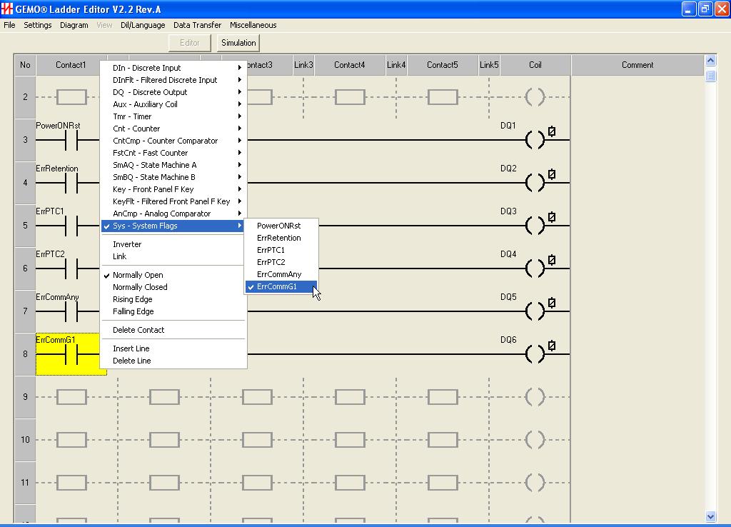
94 94/99
User s Manual Rev. A
 GEMO Ladder Editor V2.1 User s Manual Rev. A All information subject to 1/96 http://www.gemo.com.tr CONTENT 1 Introduction... 6 2 What s New... 7 2.1 What s new in Ver 2.1... 7 2.2 Abbreviation... 8 3
GEMO Ladder Editor V2.3. User s Manual Rev. B. All information subject to change without notice
 GEMO Ladder Editor V2.3 User s Manual Rev. B 1/114 CONTENT 1Introduction...7 2What s New...8 2.1What s new in Ver 2.3 Rev B...8 2.2What s new in Ver 2.3 Rev A...8 2.3What s new in Ver 2.2 Rev A...9 2.4What
GEMO Ladder Editor V2.4 User s Manual Rev. A
 GEMO Ladder Editor V2.4 User s Manual Rev. A All trademarks, service marks, trade names, product names, corporate names, company names, logos, and etc. appearing on this document are the property of their
LX3V-4AD User manual Website: Technical Support: Skype: Phone: QQ Group: Technical forum:
 User manual Website: http://www.we-con.com.cn/en Technical Support: support@we-con.com.cn Skype: fcwkkj Phone: 86-591-87868869 QQ Group: 465230233 Technical forum: http://wecon.freeforums.net/ 1. Introduction
VLC-3 USER'S MANUAL. Light Program Controller. M rev. 04 K rev. 00 & ( ( 5, 352*5$0 1 : $ 2 ' 6(77,1*6 )81&7,216
81&7,216") Light Program Controller VLC-3 USER'S MANUAL +50,1 +50,1 1 : $ ' 2 7. 6 8 ' 5, 7 6 6. $ ( 3 352*5$0 0,16(& )81&7,216 6(77,1*6 & 8 5 5 ( 1 7 3 ( 5, 2 ' M 890-00189 rev. 04 K 895-00406 rev. 00 GENERAL...
Light Program Controller VLC-3 USER'S MANUAL +50,1 +50,1 1 : $ ' 2 7. 6 8 ' 5, 7 6 6. $ ( 3 352*5$0 0,16(& )81&7,216 6(77,1*6 & 8 5 5 ( 1 7 3 ( 5, 2 ' M 890-00189 rev. 04 K 895-00406 rev. 00 GENERAL...
D-901 PC SOFTWARE Version 3
 INSTRUCTION MANUAL D-901 PC SOFTWARE Version 3 Please follow the instructions in this manual to obtain the optimum results from this unit. We also recommend that you keep this manual handy for future reference.
Installation and User Guide 458/CTR8 8-Channel Ballast Controller Module
 Installation and User Guide 458/CTR8 8-Channel Ballast Controller Module Helvar Data is subject to change without notice. www.helvar.com i Contents Section Page Introduction 1 Installation 2 1. Attach
Operating instructions Electronic preset counter Type series 717
 Operating instructions Electronic preset counter Type series 717 1. Description 5.98.3_gb 6-digit adding/subtracting counter with two presets Very bright 8mm high LED display Counting and preset range
ED3. Digital Encoder Display Page 1 of 13. Description. Mechanical Drawing. Features
 Description Page 1 of 13 The ED3 is an LCD readout that serves as a position indicator or tachometer. The ED3 can display: Speed or position of a quadrature output incremental encoder Absolute position
Dimming actuators GDA-4K KNX GDA-8K KNX
 Dimming actuators GDA-4K KNX GDA-8K KNX GDA-4K KNX 108394 GDA-8K KNX 108395 Updated: May-17 (Subject to changes) Page 1 of 67 Contents 1 FUNCTIONAL CHARACTERISTICS... 4 1.1 OPERATION... 5 2 TECHNICAL DATA...
Operating Instructions
 CNTX Contrast sensor Operating Instructions CAUTIONS AND WARNINGS SET-UP DISTANCE ADJUSTMENT: As a general rule, the sensor should be fixed at a 15 to 20 angle from directly perpendicular to the target
DTS400B - DZS400BP 3/9/07 10:14 AM Page 1
 DTS400B - DZS400BP 3/9/07 10:14 AM Page 1 18 DTS400B - DZS400BP 3/9/07 10:14 AM Page 3 TABLE OF CONTENTS Section Page Capabilities and Features.......... 1 Installation Instructions............ 2 Instructions
Short Manual. ZX2 Short Manual.doc Page 1 of 12
 Short Manual ZX2 Short Manual.doc Page 1 of 12 1 Safety precautions and correct use Please refer to the full ZX2 user manual for the detailed explanations of the safety precautions and the correct use.
Dimming actuators of the FIX series DM 4-2 T, DM 8-2 T
 Dimming actuators of the FIX series DM 4-2 T, DM 8-2 T DM 4-2 T 4940280 DM 8-2 T 4940285 Updated: Jun-16 (Subject to change) Page 1 of 70 Contents 1 FUNCTIONAL CHARACTERISTICS... 4 1.1 OPERATION... 5 2
Modbus for SKF IMx and Analyst
 User manual Modbus for SKF IMx and SKF @ptitude Analyst Part No. 32342700-EN Revision A WARNING! - Read this manual before using this product. Failure to follow the instructions and safety precautions
INSTALLATION & USER GUIDE
 INSTALLATION & USER GUIDE Digidim 458 8-Channel Dimmer STEP 1 Assemble Dimmer Unit STEP 2 Mount Dimmer Chassis STEP 3 Electrical Installation STEP 4 Attach Module and Make Connections STEP 5 Replace Cover
ZU 251. Incremental Counter Module With Analogue Output and Serial Interface. Operating Instructions. control motion interface
 control motion interface motrona GmbH Zwischen den Wegen 32 78239 Rielasingen - Germany Tel. +49 (0)7731-9332-0 Fax +49 (0)7731-9332-30 info@motrona.com www.motrona.com ZU 251 Incremental Counter Module
Night Hawk Firing System User s Manual
 Firmware Version 2.53 Page 1 of 37 Table of Contents Features of the Night Hawk Panel... 4 A reminder on the safe use of Electronic Pyrotechnic Firing Systems... 5 Night Hawk Firing Panel Controls... 6
User Manual CC DC 24 V 5A. Universal Control Unit UC-1-E. General Information SET. Universal Control Unit UC-1 Of Central Lubrication PAUSE CONTACT
 Universal Control Unit UC-1-E User Manual General Information Universal Control Unit UC-1 Of Central Lubrication CC DC 24 V 5A / M 15 SL /MK 31 M Z 30 General Information Contents Universal Control Unit
Transmitter Interface Program
 Transmitter Interface Program Operational Manual Version 3.0.4 1 Overview The transmitter interface software allows you to adjust configuration settings of your Max solid state transmitters. The following
Factory configured macros for the user logic
 Factory configured macros for the user logic Document ID: VERSION 1.0 Budapest, November 2011. User s manual version information Version Date Modification Compiled by Version 1.0 11.11.2011. First edition
USER MANUAL FOR THE ANALOGIC GAUGE FIRMWARE VERSION 1.0
 by USER MANUAL FOR THE ANALOGIC GAUGE FIRMWARE VERSION 1.0 www.aeroforcetech.com Made in the USA! WARNING Vehicle operator should focus primary attention to the road while using the Interceptor. The information
INTRODUCTION TERMINAL LAYOUTS FX2N-4AD SPECIAL FUNCTION BLOCK USER S GUIDE
 FX2N-4AD SPECIAL FUNCTION BLOCK USER S GUIDE JY992D6520B This manual contains text, diagrams and explanations which will guide the reader in the correct installation and operation of the FX2N-4AD and should
LED DRIVERS. LQC4D-V1 4 channels. User Manual FEATURES
 pag. 1/13 FEATURES Outputs: 4 x channels BUS+SEQUENCER+FADER+DIMMER+DRIVER Input: DC 12/24/48 Vdc BUS Command: DALI LOCAL Command: 4x N.O. push button (with or without memory), 0-10V, 1-10V Controls: dimmer,
ivw-fd122 Video Wall Controller MODEL: ivw-fd122 Video Wall Controller Supports 2 x 2 Video Wall Array User Manual Page i Rev. 1.
 MODEL: ivw-fd122 Video Wall Controller Supports 2 x 2 Video Wall Array User Manual Rev. 1.01 Page i Copyright COPYRIGHT NOTICE The information in this document is subject to change without prior notice
Sensor module. Safety instructions. Function Correct use. Product characteristics. Structure of the device. Operation. Ref.No.
 Sensor module Ref.No.: SM 1608 V03 Safety instructions Caution! Electrical devices may only be installed and fitted by electrically skilled persons. Non-compliance with the installation information could
KNX Dimmer RGBW - User Manual
 KNX Dimmer RGBW - User Manual Item No.: LC-013-004 1. Product Description With the KNX Dimmer RGBW it is possible to control of RGBW, WW-CW LED or 4 independent channels with integrated KNX BCU. Simple
B2 Spice A/D Tutorial Author: B. Mealy revised: July 27, 2006
 B2 Spice A/D Tutorial Author: B. Mealy revised: July 27, 2006 The B 2 Spice A/D software allows for the simulation of digital, analog, and hybrid circuits. CPE 169, however, is only concerned with the
Weekly Timer. Mounting track 50 cm (1.64 ft) length PFP-50N 1 m (3.28 ft) length PFP-100N
 length PFP-50N 1 m (3.28 ft) length PFP-100N") Weekly Timer 1/4 DIN Size Timer Features Prompted Programming and Large LCD Display 24 hours x 7 days programming using just 5 switches 16 program steps and cycle operation Two independent 15 A control
Weekly Timer 1/4 DIN Size Timer Features Prompted Programming and Large LCD Display 24 hours x 7 days programming using just 5 switches 16 program steps and cycle operation Two independent 15 A control
VIDEO GRABBER. DisplayPort. User Manual
 VIDEO GRABBER DisplayPort User Manual Version Date Description Author 1.0 2016.03.02 New document MM 1.1 2016.11.02 Revised to match 1.5 device firmware version MM 1.2 2019.11.28 Drawings changes MM 2
Chapter 23 Dimmer monitoring
 Chapter 23 Dimmer monitoring ETC consoles may be connected to ETC Sensor dimming systems via the ETCLink communication protocol. In this configuration, the console operates a dimmer monitoring system that
Weekly Time Switch. Rated time Time setting range Time division 24 hrs x 7 days 00:00 to 23:59 1min
 Weekly Time Switch Easy Programming with Large LCD Display and Interactive Functions Programming for 24 hrs x 7 days using just five switches. Sixteen program steps available. Power supply freely selectable
Filter Control FS-201
 Filter Control FS-201 1/33 Index 1 General Information...4 1.1 Equipment...4 2 Installation...5 2.1 Mechanical Installation...5 2.2 Electrical Installation...5 2.2.1 Connection Diagram...6 3 Operation...6
FX-2DA SPECIAL FUNCTION BLOCK USER'S GUIDE
 FX-2DA SPECIAL FUNCTION BLOCK USER'S GUIDE JY992D52801C This manual contains text, diagrams and explanations which will guide the reader in the correct installation and operation of the FX-2DA special
ORM0022 EHPC210 Universal Controller Operation Manual Revision 1. EHPC210 Universal Controller. Operation Manual
 ORM0022 EHPC210 Universal Controller Operation Manual Revision 1 EHPC210 Universal Controller Operation Manual Associated Documentation... 4 Electrical Interface... 4 Power Supply... 4 Solenoid Outputs...
C200H-AD002/DA002 Analog I/O Units Operation Guide
 C200H-AD002/DA002 Analog I/O Units Operation Guide Revised September 1995 Notice: OMRON products are manufactured for use according to proper procedures by a qualified operator and only for the purposes
Introduction Display...1 Mounting...1 Firmware Version...2. ADL Operation... 3
 MoTeC MDD User Manual Contents Introduction... 1 Display...1 Mounting...1 Firmware Version...2 ADL Operation... 3 1. Full ADL Display...4 2. Gain Loss Layout for ADL...6 3. Large Numeric Layout for ADL...8
SceneStyle2 User Guide
 SceneStyle2 User Guide Mode Lighting (UK) Limited. The Maltings, 63 High Street, Ware, Hertfordshire, SG12 9AD, UNITED KINGDOM. Telephone: +44 (0) 1920 462121 Facsimile: +44 (0) 1920 466881 e-mail: website:
ivw-fd133 Video Wall Controller MODEL: ivw-fd133 Video Wall Controller Supports 3 x 3 and 2 x 2 Video Wall Array User Manual Page i Rev. 1.
 MODEL: ivw-fd133 Video Wall Controller Supports 3 x 3 and 2 x 2 Video Wall Array User Manual Rev. 1.01 Page i Copyright COPYRIGHT NOTICE The information in this document is subject to change without prior
MT03A Electronic converter for flow rate transmitters
 Instructions manual MT03A Electronic converter for flow rate transmitters The art of measuring R-MI-MT03A Rev.: 0 English version PREFACE Thank you for choosing a Tecfluid S.A product. This instruction
Single cable multiswich programmer PC102W
 Single cable multiswich programmer PC102W 1. Product description The PC102W - single cable multiswich programmer (in the text - programmer) is useful instrument while configuring and troubleshooting SAT
MICROMASTER Encoder Module
 MICROMASTER Encoder Module Operating Instructions Issue 01/02 User Documentation Foreword Issue 01/02 1 Foreword Qualified Personnel For the purpose of this Instruction Manual and product labels, a Qualified
Digital differential Pressure switch Model DPS Instruction manual
 Digital differential Pressure switch Model DPS Instruction manual DPSeng_rev2 September 09 MECAIR S.r.l. Diaphragm Valves and Electronic Controls for Dust Collector Filters Via per Cinisello 97 20054 Nova
C8000. switch over & ducking
 features Automatic or manual Switch Over or Fail Over in case of input level loss. Ducking of a main stereo or surround sound signal by a line level microphone or by a pre recorded announcement / ad input.
Classroom Setup... 2 PC... 2 Document Camera... 3 DVD... 4 Auxiliary... 5
 Classroom Setup... 2 PC... 2 Document Camera... 3 DVD... 4 Auxiliary... 5 Lecture Capture Setup... 6 Pause and Resume... 6 Considerations... 6 Video Conferencing Setup... 7 Camera Control... 8 Preview
Cronotermostato Digitale
 Cronotermostato Digitale CHRONOS KEY Manuale d Uso User Manual DIGITAL PROGRAMMABLE THERMOSTAT Index Dimensions Page 4 Connection diagram Page 4 Safety warnings Page 5 Technical specifications Page 6 Display
Quick-Start for READ30
 Quick-Start for READ30 The program READ30 was written for the purpose of reading and configuring the digital pressure-transmitter of the series 30. The two features are divided into the following parts:
USER MANUAL FOR THE ANALOGIC GAUGE FIRMWARE VERSION 1.1
 by USER MANUAL FOR THE ANALOGIC GAUGE FIRMWARE VERSION 1.1 www.aeroforcetech.com Made in the USA! WARNING Vehicle operator should focus primary attention to the road while using the Interceptor. The information
12months. on-site warranty. DZE ELECTRONIC PRESSURE SWITCH for detection of overload per EN 81 2 featuring two adjustable switching points
 BUCHER PRODUCTS AVAILABLE FROM HYDRATEC DZE ELECTRONIC PRESSURE SWITCH for detection of overload per EN 81 2 featuring two adjustable switching points 12months on-site warranty All our work comes with
Special Applications Modules
 (IC697HSC700) datasheet Features 59 1 IC697HSC700 a45425 Single slot module Five selectable counter types 12 single-ended or differential inputs TTL, Non-TTL and Magnetic Pickup input thresholds Four positive
Smart Hawk Firing System User s Manual
 Firmware Version 3.09 Page 1 of 57 Table of Contents A reminder on the safe use of Electronic Pyrotechnic Firing Systems... 4 Description... 5 Common Features of the Smart Hawk Panel... 6 Features of the
Syntor X Flash Memory Module Revision C
 Syntor X Flash Memory Module Revision C The PIEXX SynXFlash memory module, along with the supplied PC software, replaces the original SyntorX code plugs and allows you to easily set modify and update your
ComfortChoice Touch Thermostat. Designed for ZigBee R Wireless Technology USER GUIDE
 ComfortChoice Touch Thermostat Designed for ZigBee R Wireless Technology USER GUIDE TABLE OF CONTENTS PAGE WELCOME... 8,9 THE TOUCH SCREEN... 10,11 Home - Inactive... 10 Home - Active... 11 PHYSICAL BUTTONS...
Electronic converter for level transmitters MT03L Instructions manual
 Electronic converter for level transmitters MT03L Instructions manual R-MI-MT03L Rev.: 1 English version PREFACE Thank you for choosing the MT03L converter from MT03 series of Tecfluid S.A. This instruction
Vorne Industries. 87/719 Analog Input Module User's Manual Industrial Drive Itasca, IL (630) Telefax (630)
 Telefax (630)") Vorne Industries 87/719 Analog Input Module User's Manual 1445 Industrial Drive Itasca, IL 60143-1849 (630) 875-3600 Telefax (630) 875-3609 . 3 Chapter 1 Introduction... 1.1 Accessing Wiring Connections
Vorne Industries 87/719 Analog Input Module User's Manual 1445 Industrial Drive Itasca, IL 60143-1849 (630) 875-3600 Telefax (630) 875-3609 . 3 Chapter 1 Introduction... 1.1 Accessing Wiring Connections
imso-104 Manual Revised August 5, 2011
 imso-104 Manual Revised August 5, 2011 Section 1 Getting Started SAFETY 1.10 Quickstart Guide 1.20 SAFETY 1.30 Compatibility 1.31 Hardware 1.32 Software Section 2 How it works 2.10 Menus 2.20 Analog Channel
MODEL OTM-4870 FREQUENCY AGILE 870MHz F.C.C. COMPATIBLE TELEVISION MODULATOR
 MODEL OTM-4870 FREQUENCY AGILE 870MHz F.C.C. COMPATIBLE TELEVISION MODULATOR USERS MANUAL Phone: (209) 586-1022 (800) 545-1022 Fax: (209) 586-1026 E-Mail: salessupport@olsontech.com 025-000412 Rev. B www.olsontech.com
Preset counters, electronic
 The multifunction preset counters Codix 923 / 924 can be used universally. These preset pulse counters, tachometers or preset timers with up to 6 presets can solve a wide variety of control and monitoring
R1MS-GH3 BEFORE USE... POINTS OF CAUTION INSTRUCTION MANUAL THERMOCOUPLE & DC INPUT MODULE MODEL. (8 points; isolated)
") INSTRUCTION MANUAL THERMOCOUPLE & INPUT MODULE (8 points; isolated) MODEL BEFORE USE... Thank you for choosing M-System. Before use, please check contents of the package you received as outlined below.
INSTRUCTION MANUAL THERMOCOUPLE & INPUT MODULE (8 points; isolated) MODEL BEFORE USE... Thank you for choosing M-System. Before use, please check contents of the package you received as outlined below.
Instruction Manual. Universal Flow Controller Model 261 / 261-EC-01
 Universal Flow Controller Model 261 / 261-EC-01 Instruction Manual Type ARS 261-EC 01 Art.-no: 82212264 Table of Contents 1. Safety Instructions 2. Product ID - Dimensions 3. Function Description 4. Installation
COMPANY. MX 9000 Process Monitor. Installation, Operating & Maintenance Manual AW-Lake Company. All rights reserved. Doc ID:MXMAN082416
 COMPANY MX 9000 Process Monitor Installation, Operating & Maintenance Manual 2016 AW-Lake Company. All rights reserved. Doc ID:MXMAN082416 1 Table of Contents Unpacking...3 Quick Guide...3 Connect to Sensor...3
Standard signal metering in wall-mounting case
 User manual AKV-2VR4C Standard signal metering in wall-mounting case Technical features: Digit height: 20 mm Colour: red Range of display: -999 9999 Wall-mounting case: black, made of ABS-plastic Protection
Quick Operation Guide of LTN7700/7600 Series NVR
 Quick Operation Guide of LTN7700/7600 Series NVR UD.6L0202B0042A02 Thank you for purchasing our product. If there is any question or request, please do not hesitate to contact dealer. This manual is applicable
VISSIM TUTORIALS This document includes tutorials that provide help in using VISSIM to accomplish the six tasks listed in the table below.
 VISSIM TUTORIALS This document includes tutorials that provide help in using VISSIM to accomplish the six tasks listed in the table below. Number Title Page Number 1 Adding actuated signal control to an
COMFORT COMFORT CALL OWNER S MANUAL CALL SYSTEM P/N P BASE STATION & RF WIRELESS MODULE. Complete Control from TOTALINE
 OWNER S MANUAL COMFORT CALL SYSTEM P/N P374-0433 COMFORT BASE STATION & RF WIRELESS MODULE CALL TOTALINE REMOTE THERMOSTAT ACCESS Compatible with thermostat models: P374-700, P374-800, P374-900, P374-2700,
ANALOG I/O MODULES AD268 / DA264 / TC218 USER S MANUAL
 UM-TS02 -E026 PROGRAMMABLE CONTROLLER PROSEC T2-series ANALOG I/O MODULES AD268 / DA264 / TC218 USER S MANUAL TOSHIBA CORPORATION Important Information Misuse of this equipment can result in property damage
Process Transmitter RMA 422
 Technical Information TI 072R/24/ae Process Transmitter RMA 422 Multi-functional 1-2 channel top hat DIN rail unit with loop power supply, alarm set point monitoring, mathematics function and 1-2 analog
MARCO CORNER, 19/ THIENE (VI) ITALIA
 ITALIA") DECLARATION OF CONFORMITY KOLVER S.r.l. VIA MARCO CORNER, 19/21 36016 THIENE (VI) ITALIA Declare that the new machine here described: ACE Screw Counter Is in conformity with the following standards and
DECLARATION OF CONFORMITY KOLVER S.r.l. VIA MARCO CORNER, 19/21 36016 THIENE (VI) ITALIA Declare that the new machine here described: ACE Screw Counter Is in conformity with the following standards and
TASKI Service Tool Edition: V5.10/2014
 Edition: V5.10/2014 Index 1 General 1.1 General information 1 1.1.1 Part reference 1 1.1.2 Consumable supplies 1 1.1.3 Direction description 1 1.1.4 Power source 1 1.2 Required material 2 1.2.1 Tools 2
Automatic Transfer Switch Control PLC Operator s Manual
 MTS Power Products MIAMI FL 33142 ATS-22AG Automatic Transfer Switch Control PLC Operator s Manual Dedicated Single Phase Transfer Switch ATS-22AG Automatic Transfer Switch INTRODUCTION 1.1 Preliminary
C8188 C8000 1/10. digital audio modular processing system. 4 Channel AES/EBU I/O. features. block diagram. 4 balanced AES inputs
 features 4 balanced AES inputs Input Sample Rate Converters (SRC) 4 balanced AES outputs Relay bypass for pairs of I/Os Relay wait time after power up Master mode (clock master for the frame) 25pin Sub-D,
Compatibility mode. rev. 0.1, 10/09/2015. Compatibility mode Sx tool manual 1
 Compatibility mode rev. 0.1, 10/09/2015 1 Index 1 COMPATIBILITY MODE FOR DUPLINE... 4 1.1 How to enable the Dupline compatibility in the Sx tool... 5 1.2 How to manage the Dupline network in a Sx2WEB24
Instruction manual for 5024 Weighing Terminal
 Instruction manual for 5024 Weighing erminal Basic system with Analog output, Ethernet connectivity and Profibus or DeviceNet connectivity. Article no. E67X000005024 ESE02162EN Date of issue: August 11,
ENGR 1000, Introduction to Engineering Design
 Unit 2: Mechatronics ENGR 1000, Introduction to Engineering Design Lesson 2.3: Controlling Independent Systems Hardware: 12 VDC power supply Several lengths of wire NI-USB 6008 Device with USB cable Digital
Industriefunkuhren. Technical Manual. IRIG-B Generator-Module for analogue / digital Signals of Type: IRIG-B / IEEE C / AFNOR NF S87-500
 Industriefunkuhren Technical Manual IRIG-B Generator-Module for analogue / digital Signals of Type: IRIG-B / IEEE C37.118 / AFNOR NF S87-500 Module 7628 ENGLISH Version: 02.01-06.03.2013 2 / 20 7628 IRIG-B
Wilkes Repair: wilkes.net River Street, Wilkesboro, NC COMMUNICATIONS
 1 Wilkes COMMUNICATIONS 336.973.3103 877.973.3104 Repair: 336.973.4000 Email: wilkesinfo@wilkes.net wilkes.net 1400 River Street, Wilkesboro, NC 28697 2 Table of Contents REMOTE CONTROL DIAGRAM 4 PLAYBACK
Single Axis Position Controller
 SERIES P9511 Single Axis Position Controller Compact Construction Simple Go-to operation Integrated Relay Output Integrated Mains Power Supply ELEKTRO-TRADING sp. Z o.o. 44-109 Gliwice, ul. Mechaników
FRQM-2 Frequency Counter & RF Multimeter
 FRQM-2 Frequency Counter & RF Multimeter Usage Instructions Firmware v2.09 Copyright 2007-2011 by ASPiSYS Ltd. Distributed by: ASPiSYS Ltd. P.O.Box 14386, Athens 11510 (http://www.aspisys.com) Tel. (+30)
Label Applicator HERMA 400
 Label Applicator HERMA 400 Info GB V6.0 / 30.3.07 [ Facts & Data ] R Constructional variant Right-hand or left-hand version, always flexible to use L Power supply / Line voltage Max. power consumption
REMOTE I/O R30 SERIES. PC CONFIGURATOR SOFTWARE Model: R30CFG Ver Users Manual
 REMOTE I/O R30 SERIES PC CONFIGURATOR SOFTWARE Model: R30CFG Ver. 1.13 Users Manual 5-2-55, Minamitsumori, Nishinari-ku, Osaka 557-0063 JAPAN Tel: +81-6-6659-8201 Fax: +81-6-6659-8510 http://www.m-system.co.jp/
USER GUIDE. Get the most out of your DTC TV service!
 TV USER GUIDE Get the most out of your DTC TV service! 1 800-367-4274 www.dtccom.net TV Customer Care Technical Support 615-529-2955 615-273-8288 Carthage Area Carthage Area 615-588-1277 615-588-1282 www.dtccom.net
SCALE & WEIGHT DISPLAYS
 The MICRO SERIES SCALE & WEIGHT DISPLAYS LARGE DIGIT MODELS Mighty-5S DPM MODELS Micro-S & Mighty-1S Mighty-1S Micro-S ELECTRO-NUMERICS, INC. Introduction The Electro-Numerics family of Digital Panel Meters
Preset Counters. X e. X d 6.92 X. 0. IP khz Batch. LCD Preset Counters 1, 2, 4 or 6 Presets. Multifunction. Fast and user-friendly
 The Codix 923/924 can be used universally. As a preset pulse counter, tachometer or preset timer with up to 6 presets it is able to solve a very wide range of control and monitoring tasks in every application.
Tech Support: Customer Service: General Tech Questions: Tech Docs:
 Tech Support: 1-800-407-4545 Customer Service: 1-800-523-2462 General Tech Questions: Tech_Services@beainc.com Tech Docs: www.beasensors.com BR3-X Programmable 3 Relay Advanced Logic Module & Restroom
UDC100 Universal Digital Controller. Specification. Overview. Features. Features, continued /99 Page 1 of 4
 UDC100 Universal Digital Controller 51-52-03-29 11/99 Page 1 of 4 Specification Overview The UDC100 Universal Digital Controller is a microprocessor-based 1/4 DIN low cost temperature controller. It combines
ENGR 1000, Introduction to Engineering Design
 ENGR 1000, Introduction to Engineering Design Unit 2: Data Acquisition and Control Technology Lesson 2.4: Programming Digital Ports Hardware: 12 VDC power supply Several lengths of wire NI-USB 6008 Device
SNG-2150C User s Guide
 SNG-2150C User s Guide Avcom of Virginia SNG-2150C User s Guide 7730 Whitepine Road Revision 001 Richmond, VA 23237 USA GENERAL SAFETY If one or more components of your earth station are connected to 120
SAT IF distribution system
 7. Technical specifications Type cs43 RF input frequency range pr. 50-350 MHz inputs number 4 level pr. 55...88 dbµv 60...93 dbµv symbol rate 3 45 Ms/s return loss/impedance > 0 db/75 Ω LNB powering/control
16-CH Color Full Duplex Multiplexer Instruction Manual
 16-CH Color Full Duplex Multiplexer Instruction Manual 707-V1.5(S) Index: 1. Safety Warning 3 2. Introduction 3 3. Features 4 4. Specification 5 5. Front Panel Keypad 6 6. Back Panel Connection 10 7. Menu
Philips LightMaster. KNX Timeclock Installation and Operation Manual
 Philips LightMaster KNX Timeclock Installation and Operation Manual Philips LightMaster KNX Timeclock Installation and Operation Manual version 1.1 Specifications subject to change without notice. Copyright
GV 460 / GV 461 Impulse Splitters for Incremental Encoders with Potential Separation between Input and Outputs
 control motion interface GV 460 / GV 461 Impulse Splitters for Incremental Encoders with Potential Separation between Input and Outputs GV 480 / GV 481 Impulse Splitters for Incremental Encoders with all-around
EDL8 Race Dash Manual Engine Management Systems
 Engine Management Systems EDL8 Race Dash Manual Engine Management Systems Page 1 EDL8 Race Dash Page 2 EMS Computers Pty Ltd Unit 9 / 171 Power St Glendenning NSW, 2761 Australia Phone.: +612 9675 1414
Transponder Reader TR22A01KNX TR22A11KNX. Product Handbook
 Transponder Reader TR22A01KNX TR22A11KNX Product Handbook Product: Transponder Reader Order Code: TR22A01KNX - TR22A11KNX Application Program ETS: EEL_RDT1_10 Transponder Card Reader Pagina 1 di 24 Index
Celect Communications. Complete TV Users Guide
 Celect Communications Complete TV Users Guide 1 Contents Setting up your Remote... 4 Remote Guide... 5 Using the Guide Button... 8 Searching...10 Reminders...12 DVR Guide...13 Important Note...26 TV Main
Extra long-range RFID (proximity) card reader
 card reader") GP90A Extra long-range RFID (proximity) card reader (1) Features: Extra long reading range of up to 90 cm with ISO-size passive RFID cards*, over 100 cm with special optimized passive cards High-precision
GP90A Extra long-range RFID (proximity) card reader (1) Features: Extra long reading range of up to 90 cm with ISO-size passive RFID cards*, over 100 cm with special optimized passive cards High-precision
ex 800 Series ematrix System
 Protecting Your Human Assets During Emergency ex 800 Series ematrix System The ex 800 Series ematrix System is a fully integrated and versatile public address system which is designed distinctively to
Multifunction Digital Timer
 Multifunction Digital Timer 72 x72 mm Timer with Easy-to-use Functions Nine output modes accommodate a wide variety of applications. All parameters set by scroll-through menus accessed from the front panel.
imso-104 Manual Revised July 19, 2012
 imso-104 Manual Section 1 Getting Started SAFETY 1.10 Quickstart Guide 1.20 SAFETY 1.30 Compatibility 1.31 Hardware 1.32 Software Section 2 How it works 2.10 Menus 2.20 Analog Channel 2.21 On / Off 2.22
Gamma instabus. Technical product information
 Gamma instabus Technical product information Universal dimmer N 554D31, 4 x 300 VA / 1x 1000 VA, AC 230 V Universal dimmer N 554D31 Control of dimmable lamps, including LED without minimum load Output
RS232 Connection. Graphic LCD Screen. Power Button. Charger Adapter Input LNB Output. MagicFINDER Digital SatLock Operating Manual
 GENERAL FEATURES Easy-to-understand user-friendly menu and keypad. LNB short circuit protection. Display of Analog Signal Level, Digital Signal Quality with % and Bar, audible notification. Timer Lock,