D-ATV.com s IQ modulator switch. 30 October 2004
|
|
|
- Dustin Nash
- 5 years ago
- Views:
Transcription
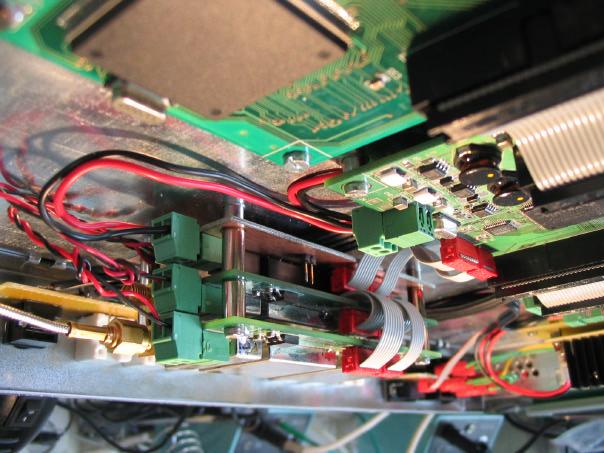
1 D-ATV.com Digitally Rearranging the Spectrum D-ATV.com s IQ modulator switch sales@d-atv.com 0 October 00 Internet: Introduction The D-ATV.com DVB-S modulator boards consist of a FPGA baseband board, MPEG encoder and an IQ modulator. We have currently two different IQ modulators available, one for the cm frequency range and one for 1cm frequency range. We deliberately designed two different IQ modulators for the two frequeny bands because we wanted to achieve maximum performance on both frequency bands, something which will be harder to achieve when combining the designs. On the other hand there seems to be much interest for using two different IQ modulators running with a single D-ATV baseband board. Therefore we created a simple but effective design which enables you to use both IQ modulators with the existing D-ATV board. The design The design of the IQ switch is rather straightforward. The design uses simple relays for interconnecting the appropriate IQ modulator to the FPGA baseband board. The relays are controlled by a single NPN transistor which is driven with a low voltage level coming from the D-ATV baseband board. Look in the D- ATV connections.pdf document for finding the correct output on the baseband board to drive the IQ modulator band switch. The IQ switch need to be supplied with an external 1V. A separate relay is available for driving the power supply to the both IQ modulator units. This relay is also controlled by the same transistor. The full schematic diagram of the IQ switch is shown in the appendix. The PCB board The PCB layout and component placement are shown in the appendix. The PCB layout is printed on a 1:1 scale and prepared for direct printing on a film. The dimensions of the PCB are the same as for the IQ modulators which equals to 100 x 5 mm. The PCB is double sided where the toplayer is mainly functioning as a ground layer. Important notes Care must be taken to keep interconnection cables as short as possible. Too long cables result in distortion of the transmitted frequency spectrum. Best performance is achieved when the IQ switch and the two IQ modulators are sandwiched. In that case the IQ switch is placed at the bottom, following up to the top respectively the 1cm IQ modulator and above the cm IQ modulator. We included some photographs to show you how we worked this out on our own prototypes. How to get it? In principle you are free to make your own IQ switch based on the info found in this document. You have to etch your own PCB and you have to buy your parts at Farnell ( If you prefer to buy a ready made unit instead of buying all the components by yourself and putting it on a home etched board, then you can contact us.

2 D-ATV.com Digitally Rearranging the Spectrum

3 D-ATV.com Digitally Rearranging the Spectrum
4 1 A B JP PLL_DATA PLL_LOCK 1 1Volt conn. JP PLL conn. PLL_CLK PLL_LE PLL_DATA PLL_CLK PLL_LOCK PLL_LE K K PLL_DATA1 PLL_DATA PLL_CLK1 PLL_CLK PLL_LOCK1 PLL_LOCK PLL_LE1 PLL_LE PLL_DATA1 PLL_LOCK1 PLL_DATA PLL_LOCK JP1 PLL conn. cm JP PLL conn. 1cm JP5 1 Header PLL_CLK1 PLL_LE1 PLL_CLK PLL_LE Switched supply outputs to supply inputs of the both IQ modulators A B C JP DAC In V06-A100-B01 K JP6 7 8 DAC Out JP7 7 8 DAC Out C D1 D JP9 1 Header Diode R1 1K Q1 NPN Title D 1 Size A Number Date: 10/0/00 Sheet of File: G:\Protel\IQ switch\iq switch.schdoc Drawn By: Revision
5 Description Designator Quantity 1N18 D1 1 Micro Match 6 pin connector Farnell JP1 1 Micro Match 6 pin connector Farnell JP 1 Micro Match 6 pin connector Farnell JP 1 Header, -Pin, MC1.5/-G-.81 Farnell JP 1 Header, -Pin JP5 1 Micro Match 8 pin connector Farnell JP6 1 Micro Match 8 pin connector Farnell JP7 1 Micro Match 8 pin connector Farnell JP8 1 Header, -Pin JP9 1 PCO - G6A-P Series relais Farnell 1760 K1 1 PCO - G6A-P Series relais Farnell 1760 K 1 Relay Farnell 9 K 1 BC86B Q1 1 Resistor R1 1
6
7
8
TR-Plus T/R Switch Assembly and Operation Manual. Introduction
 TR-Plus T/R Switch Assembly and Operation Manual Revised: 7 February 2015 2015 Tucson Amateur Packet Radio Corporation Introduction The TAPR TR-Plus is a transmit/receive ( T/R ) switch that connects a
2011 ARRL TAPR Digital Comm Conference
 2011 ARRL TAPR Digital Comm Conference by Charles Brain G4GUO@ARRL.net Ken Konechy W6HHC@ARRL.net G4GUO W6HHC Status of Digital-ATV Today Video Quality of DATV far exceeds analog-atv Very few hams transmitting
2013 ARRL/TAPR DCC. DATV-Express
 2013 ARRL/TAPR DCC a Testing Report by Art Towslee towslee1@ee.net Ken Konechy W6HHC@ARRL.net WA8RMC W6HHC The Presentation Authors. Art WA8RMC Ken W6HHC 2 103 Status of Digital-ATV Today Video Quality
Digital Effects Pedal Description Ross Jongeward 10 December 2014
 Digital Effects Pedal Description Ross Jongeward 10 December 2014 1 Contents Section Number Title Page 1.1 Introduction..3 2.1 Project Electrical Specifications..3 2.1.1 Project Specifications...3 2.2.1
Multi-Key v2.4 Multi-Function Amplifier Keying Interface
 Multi-Key v2.4 Multi-Function Amplifier Keying Interface ASSEMBLY & OPERATION INSTRUCTIONS INTRODUCTION The Harbach Electronics, LLC Multi-Key is a multi-function external device designed for the safe
SingMai Electronics SM06. Advanced Composite Video Interface: DVI/HD-SDI to acvi converter module. User Manual. Revision th December 2016
 SM06 Advanced Composite Video Interface: DVI/HD-SDI to acvi converter module User Manual Revision 0.3 30 th December 2016 Page 1 of 23 Revision History Date Revisions Version 17-07-2016 First Draft. 0.1
Build Your Own Clone Relay Bypass Board Instructions
 Build Your Own Clone Relay Bypass Board Instructions Parts list for the Relay Bypass Board Resistors: 1-2k2/222 (Red/Red/Black/Brown/Brown) 1-10k/103 (Brown/Black/Black/Red/Brown) Capacitors: 2-100n/.1uF/104
ALM-6813/6812 INSTALLATION AND PROGRAMMING MANUAL
 ALM-6813/6812 INSTALLATION AND PROGRAMMING MANUAL Installation and programming Manual v2.2 1 MARSS Solar Defender SYSTEM This guidebook provides the essential instructions to install and configure the
Device for a inserting text into a video-signal
 ATV-LOGO Device for a inserting text into a video-signal 1998 2000 Wolfgang Otterbach, DL1IE All rights reserved. 10/2000 General The ATV-LOGO is an inexpensive but stable device for inserting text into
Appeal decision. Appeal No USA. Osaka, Japan
 Appeal decision Appeal No. 2014-24184 USA Appellant BRIDGELUX INC. Osaka, Japan Patent Attorney SAEGUSA & PARTNERS The case of appeal against the examiner's decision of refusal of Japanese Patent Application
SingMai Electronics SM06. Advanced Composite Video Interface: HD-SDI to acvi converter module. User Manual. Revision 0.
 SM06 Advanced Composite Video Interface: HD-SDI to acvi converter module User Manual Revision 0.4 1 st May 2017 Page 1 of 26 Revision History Date Revisions Version 17-07-2016 First Draft. 0.1 28-08-2016
Digital Amateur TeleVision (D-ATV)
") Digital Amateur TeleVision (D-ATV) Thomas Sailer, HB9JNX/AE4WA, Wolf-Henning Rech, DF9IC/N9EOW, Stefan Reimann, DG8FAC, Jens Geisler, DL8SDL August 7, 2001 Abstract In this article, we present a Digital
Digital Amateur TeleVision (D-ATV) Thomas Sailer, HB9JNX/AE4WA, Wolf-Henning Rech, DF9IC/N9EOW, Stefan Reimann, DG8FAC, Jens Geisler, DL8SDL August 7, 2001 Abstract In this article, we present a Digital
Parts Checklist - Please note there is no resistor R3. Diodes, LED and transistors are polarized see construction stages
 Xtal Check Kit build Read me first! -------- UPDATED GUIDE------ September 12, 2018--------- The following steps are designed to get your Xtal check kit built and operational. This is a good beginner s
GEKCO SUBCARRIER REFERENCE OSCILLATOR MODEL SRO10 OPERATION/SERVICE MANUAL
 GEKCO MODEL SRO10 SUBCARRIER REFERENCE OSCILLATOR OPERATION/SERVICE MANUAL GEKCO Labs PO Box 642 Issaquah, WA 98027 (425) 392-0638 P/N 595-431 REV 5/98 Copyright c 1998 GEKCO Labs All Rights Reserved Printed
ANTUMBRA FADE MANUAL
 ANTUMBRA FADE MANUAL TABLE OF CONTENTS 01. INSTALLATION 4 02. BACK 5 03. FRONT 6 04. USE 7 05. LINK 8 06. BILL OF MATERIALS 9 07. BUILD NOTES 10 08. BACK 11 09. FRONT 14 10. MODIFICATION 15 11. FINISHED
Dynamic Animation Cube Group 1 Joseph Clark Michael Alberts Isaiah Walker Arnold Li
 Dynamic Animation Cube Group 1 Joseph Clark Michael Alberts Isaiah Walker Arnold Li Sponsored by: Department of Electrical Engineering & Computer Science at UCF What is the DAC? The DAC is an array of
Mal-2 assembly guide v1.0
 Mal-2 assembly guide v.0 SONIC POTIONS Schematic and BOM The BOM can be found on Google Docs Prepare the PCB Separate the PCBs using some pliers. PCB We start with the lower PCB and assemble it beginning
University of Arizona January 18, 2000 Joel Steinberg Rev. 1.6
 I/O Specification for Serial Receiver Daughter Board (PCB-0140-RCV) (Revised January 18, 2000) 1.0 Introduction The Serial Receiver Daughter Board accepts an 8b/10b encoded serial data stream, operating
Self-Playing Xylophone
 Self-Playing Xylophone Matt McKinney, Electrical Engineering Project Advisor: Dr. Tony Richardson April 1, 2018 Evansville, Indiana Acknowledgements I would like to thank Jeff Cron, Dr. Howe, and Dr. Richardson
16-BIT LOAD CELL/DUAL STATUS INPUT
 16-BIT LOAD CELL/DUAL STATUS INPUT On-board Excitation. +5VDC, (120mA). State-of-the-art Electromagnetic Noise Suppression Circuitry. Ensures signal integrity even in harsh EMC environments. Optional Excitation
Fixed Audio Output for the K2 Don Wilhelm (W3FPR) & Tom Hammond (NØSS) v August 2009
 & Tom Hammond (NØSS) v August 2009") Fixed Audio Output for the K2 Don Wilhelm (W3FPR) & Tom Hammond (NØSS) v. 2.1 06 August 2009 I have had several requests to provide a fixed audio output from the K2. After looking at the circuits that
Fixed Audio Output for the K2 Don Wilhelm (W3FPR) & Tom Hammond (NØSS) v. 2.1 06 August 2009 I have had several requests to provide a fixed audio output from the K2. After looking at the circuits that
COLOUR CHANGING USB LAMP KIT
 TEACHING RESOURCES SCHEMES OF WORK DEVELOPING A SPECIFICATION COMPONENT FACTSHEETS HOW TO SOLDER GUIDE SEE AMAZING LIGHTING EFFECTS WITH THIS COLOUR CHANGING USB LAMP KIT Version 2.1 Index of Sheets TEACHING
PART. Maxim Integrated Products 1
 9-646; Rev 0; /00 General Description The MAX94 evaluation kit (EV kit) is assembled with a MAX94 and the basic components necessary to evaluate the -bit analog-to-digital converter (ADC). Connectors for
Dust Sensor using GP Y
 Dust Sensor using GP Y Dust sensors detect fine dust ( aerosol ) floating in the air. They are used to determine air quality indoor and outdoor. Limits of the GP2Y10 The GP2Y10 sensor was developed to
PHILIPS Anubis A(AC) Chassis
 Chassis") PHILIPS Anubis A(AC) Chassis Recommended Safety Parts Item Part No. Description 4822 276 12597 MAIN SWITCH 4822 258 30274 FUSE HOLDER 4822 255 40955 LED HOLDER 4822 267 60243 EURO CONN. 4822 265 30389
PHILIPS Anubis A(AC) Chassis Recommended Safety Parts Item Part No. Description 4822 276 12597 MAIN SWITCH 4822 258 30274 FUSE HOLDER 4822 255 40955 LED HOLDER 4822 267 60243 EURO CONN. 4822 265 30389
QUIZ BUZZER KIT TEACHING RESOURCES. Version 2.0 WHO ANSWERED FIRST? FIND OUT WITH THIS
 TEACHING RESOURCES SCHEMES OF WORK DEVELOPING A SPECIFICATION COMPONENT FACTSHEETS HOW TO SOLDER GUIDE WHO ANSWERED FIRST? FIND OUT WITH THIS QUIZ BUZZER KIT Version 2.0 Index of Sheets TEACHING RESOURCES
Nutube.US. 6P1 Evaluation Board. User Manual
 Nutube.US 6P1 Evaluation Board User Manual Introduction The 6P1 Evaluation Board (EVB) is a vehicle for testing and evaluating the Korg Nutube 6P1 dual triode in audio circuits. This product is designed
Amateur TV Receiver By Ian F Bennett G6TVJ
 Amateur TV Receiver By Ian F Bennett G6TVJ Here is a design for an ATV receiver which makes use of a Sharp Satellite tuner module. The module was bought from "Satellite Surplus" at a rally a year or so
DMC550 Technical Reference
 DMC550 Technical Reference 2002 DSP Development Systems DMC550 Technical Reference 504815-0001 Rev. B September 2002 SPECTRUM DIGITAL, INC. 12502 Exchange Drive, Suite 440 Stafford, TX. 77477 Tel: 281.494.4505
JTAG-SMT1 Programming Module for Xilinx FPGAs. Overview. 23 mm. 21.5mm. Revised November 21, 2017 This manual applies to the JTAG-SMT1 rev.
 1300 Henley Court Pullman, WA 99163 509.334.6306 www.digilentinc.com JTAG-SMT1 Programming Module for Xilinx FPGAs Revised November 21, 2017 This manual applies to the JTAG-SMT1 rev. A Overview The JTAG-SMT1
CHAPTER 9. Actives Devices: Diodes, Transistors,Tubes
 CHAPTER 9 Actives Devices: Diodes, Transistors,Tubes 1 The electrodes of a semiconductor diode are known as anode and cathode. In a semiconductor diode, electrons flow from cathode to anode. In order for
LED Backlight for Technics amplifiers
 LED Backlight for Technics amplifiers Technics SE-A900S Technics SE-A900SM2 Technics SE-A909S Technics SE-A1000 Technics SE-A1000M2 Technics SE-A1010 Rev. 1.2 B Description The LED module is designed to
DIY KIT MHZ 8-DIGIT FREQUENCY METER
 This kit is a stand-alone frequency meter capable of measuring repetitive signals up to a frequency of 50MHz. It has two frequency ranges (15 and 50 MHz) as well as two sampling rates (0.1 and 1 second).
MONO AMPLIFIER KIT ESSENTIAL INFORMATION. Version 2.2 CREATE YOUR OWN SPEAKER DOCK WITH THIS
 ESSENTIAL INFORMATION BUILD INSTRUCTIONS CHECKING YOUR PCB & FAULT-FINDING MECHANICAL DETAILS HOW THE KIT WORKS CREATE YOUR OWN SPEAKER DOCK WITH THIS MONO AMPLIFIER KIT Version 2.2 Build Instructions
EPROM pattern generator with "Genlock"
 EPROM pattern generator with "Genlock" This generator uses an EPROM to store several pictures that can then be selected by means of a thumb-wheel switch. Alternatively, if the pictures stored are in a
SEP Bright Pi v1.0 Assembly Instructions
 SEP Bright Pi v1.0 Assembly Instructions When you purchased your Bright Pi v1.0 kit, you should have received an anti-static bag with some components in it which will require soldering together in order
This document is intended to provide information to allow the researcher to build their own device.
 SEXTA Construction Notes Tony Barry, Dave Gault Preamble:- SEXTA is a system (hardware device, firmware, and application software) to create and analyse optical timestamps as observed by a camera and recorder.
C-MAX. CMM-9301-V3.1S Bluetooth 4.0 Single Mode HCI Module. Description. 1.1 Features
 Description This Module is limited to OEM installation ONLY The module is a Bluetooth SIG qualified, miniaturised BLE controller module based on EM Microelectronic's low power fully integrated single-chip
MAMX Sub-Harmonic Pumped Mixer GHz Rev. V1. Functional Schematic. Features. Description. Pin Configuration 1
 MAMX-119 Features Up or Down Frequency Mixer Low Conversion Loss: 11 db 2xLO & 3xLO Rejection: db RF Frequency: 14 - LO Frequency: 4-2 GHz IF Frequency: DC - 7 GHz Lead-Free 1.x1.2 mm 6-lead TDFN Package
MAX2660/MAX2661/MAX2663/MAX2671 Evaluation Kits
 9-382; Rev ; 9/99 MAX2660/MAX266/MAX2663/MAX267 General Description The MAX2660/MAX266/MAX2663/MAX267 evaluation kits simplify evaluation of the MAX2660/MAX266/ MAX2663/MAX267 upconverter s. They enable
WM8725 EVALUATION BOARD USER HANDBOOK. The WM8725 is high performance Stereo DAC.
 w WM8725-EVM WM8725 EVALUATION BOARD USER HANDBOOK INTRODUCTION The WM8725 is high performance Stereo DAC. This evaluation platform and documentation should be used in conjunction with the latest version
Evaluation Board for CS4954/55
 Evaluation Board for CS4954/55 Features l Demonstrates recommended layout and grounding practices l Supports both parallel and serial digital video input l On-board test pattern generation l Supports NTSC/PAL
Introduction 1. Green status LED, controlled by output signal ST. Sounder, controlled by output signal Q6. Push switch on input D6
 Introduction 1 Welcome to the GENIE microcontroller system! The activity kit allows you to experiment with a wide variety of inputs and outputs... so why not try reading sensors, controlling lights or
(((((((((<<<<<<<<<<<<<<<<<<<<Q
 Application Note AN-0010 TR-3200 Tally Router Application Guide Quartz routers are often used to route signals to a vision mixer that is feeding a transmission path. In this situation users need to know
7 SegmneDisplay Unit With High Bright Characters (D1SC-N : W32 H57mm, D1SA Series: W11 H22mm)
") SC-N/SA Series 7 Segment Display Unit 7 SegmneDisplay Unit With High Bright Characters (SC-N : W32 H57mm, SA Series: W H22mm) Features Selectable decimal (0 to 9) or hexadecimal (0 to 9, A to F) indication
SC-N/SA Series 7 Segment Display Unit 7 SegmneDisplay Unit With High Bright Characters (SC-N : W32 H57mm, SA Series: W H22mm) Features Selectable decimal (0 to 9) or hexadecimal (0 to 9, A to F) indication
H2633IP-1 RELAY CARD K2633
 H2633IP-1 RELAY CARD K2633 Control up to 4 high-power circuits from a low-power drive circuit. Features & Specifications The connection of a few relays to the outputs of an electronic circuit might be
This Unit may form part of a National Qualification Group Award or may be offered on a free standing basis.
 National Unit Specification: general information CODE F5JJ 11 SUMMARY The Unit is intended for candidates with little or no prior knowledge of Analogue or Digital Electronic Circuits. It provides an opportunity
Build A Video Switcher
 Build A Video Switcher VIDEOSISTEMAS serviciotecnico@videosistemas.com www.videosistemas.com Reprinted with permission from Electronics Now Magazine September 1997 issue Copyright Gernsback Publications,
Quad 7-segment display board
 Quad 7-segment display board www.matrixtsl.com EB008 Contents About this document 3 Board layout 3 General information 4 Circuit description 4 Protective cover 5 Circuit diagram 6 2 Copyright About this
Bill of Materials: Super Simple Water Level Control PART NO
 Super Simple Water Level Control PART NO. 2169109 Design a simple water controller in which electrodes are required to sense high and low water levels in a tank. Whenever the water level falls below the
Introduction 1. Green status LED, controlled by output signal ST
 Introduction 1 Welcome to the magical world of GENIE! The project board is ideal when you want to add intelligence to other design or electronics projects. Simply wire up your inputs and outputs and away
Introduction 1. Digital inputs D6 and D7. Battery connects here (red wire to +V, black wire to 0V )
") Introduction 1 Welcome to the magical world of GENIE! The project board is ideal when you want to add intelligence to other design or electronics projects. Simply wire up your inputs and outputs and away
Introduction 1 Welcome to the magical world of GENIE! The project board is ideal when you want to add intelligence to other design or electronics projects. Simply wire up your inputs and outputs and away
INTRODUCTION TO ELECTRICAL & COMPUTER ENGINEERING EAGLE PROJECT
 INTRODUCTION TO ELECTRICAL & COMPUTER ENGINEERING EAGLE PROJECT Assistant Professor: Xingwei Wang WHAT IS EAGLE Eagle WHAT IS EAGLE Eagle (Easily Applicable Graphical Layout Editor) WHAT IS EAGLE Eagle
Bill of Materials: Magic Color PART NO
 Magic Color PART NO. 2193838 Magic color is a guessing game. With this game you can surprise your friends and leave them with amazement, how the game guesses what they have in their minds. Only two selections
EZCOM-1. PLC - to - AMS MESSAGE DISPLAY INTERFACE INSTALLATION AND OPERATING INSTRUCTIONS. Rev March, 2001
 EZCOM-1 PLC - to - AMS MESSAGE DISPLAY INTERFACE INSTALLATION AND OPERATING INSTRUCTIONS Rev 1.3 - March, 2001 CONTENTS Page INTRODUCTION 1 SPECIFICATIONS 1 LIST OF SUPPLIED ITEMS 1 INSTALLATION & TESTING
Specifications. FTS-260 Series
 Specifications DVB-S2 NIM Tuner Date : 2014. 03. 26. Revision F2 #1501, Halla sigma Valley, 442-2 Sangdaewon-dong, Jungwon-gu, Sungnam City, Gyeonggi-do, Korea, 462-807 Tel. 86-755-26508927 Fax. 86-755-26505315-1
Commsonic. ISDB-S3 Modulator CMS0070. Contact information
 ISDB-S3 Modulator CMS0070 Fully compliant with ARIB STD-B44. Variable sample-rate interpolation provides ultra-flexible clocking strategy BPSK, QPSK, 8-PSK, 16-APSK and 32-APSK supported. Integrated LDPC
Commsonic. Multi-channel ATSC 8-VSB Modulator CMS0038. Contact information. Compliant with ATSC A/53 8-VSB
 Multi-channel ATSC 8-VSB Modulator CMS0038 Compliant with ATSC A/53 8-VSB Scalable architecture supports 1 to 4 channels per core, and multiple instances per FPGA. Variable sample-rate interpolation provides
ADE-60 4:4 MIX UTILITY
 ADE-60 4:4 MIX UTILITY Cascading, 4-Channel, Mix & CV Utility with user-configurable options for 2x Gain, Attenuversion, Biasing & CV. 2017 Abstract Data Ltd. http://www.abstractdata.biz Version 1.0.2
RIN+, ROUT_1, ROUT_2, R1, R2, R3, R21 R24. Maxim Integrated Products 1
 9-3905; Rev ; /07 MAX4079 Evaluation Kit General Description The MAX4079 evaluation kit (EV kit) is a fully assembled and tested surface-mount printed circuit board (PCB). The MAX4079 filters and buffers
Capacitor Sounds II - Standalone Distortion Meter.
 Capacitor Sounds II - Standalone Distortion Meter. This article was written for the September 2003 issue of Electronics World. All measurements to date for this series were made using the test equipment,
Update on DATV-Express exciter for Digital-ATV
 2015 ARRL/TAPR DCC by Update on DATV-Express exciter for Digital-ATV Ken Konechy W6HHC W6HHC@ARRL.net Abstract - The old technology of analog-atv suffers from susceptibility to snow and multi-path ghost
Bill of Materials: 7-Segment LED Die with Arduino PART NO
 7-Segment LED Die with Arduino PART NO. 2190194 This project is based on the Arduino environment so that you can manipulate a die with a simple common anode 7-segment LED, a transistor PNP-2N3906, 10 resistors
SDI-MP1010-GM-60P-M-RA 3G/HD-SDI Output Video Transceiver. SDI-MP1010-GM-60P-M-RA Features. Block Diagram SDI-MP1010-GM-60P-M-RA.
 This is a family of small form factor modules for formatting and converting generic digital video streams to standard compliant formats. Different interface standards are supported from the transmitter
Vorne Industries. 87/719 Analog Input Module User's Manual Industrial Drive Itasca, IL (630) Telefax (630)
 Telefax (630)") Vorne Industries 87/719 Analog Input Module User's Manual 1445 Industrial Drive Itasca, IL 60143-1849 (630) 875-3600 Telefax (630) 875-3609 . 3 Chapter 1 Introduction... 1.1 Accessing Wiring Connections
Vorne Industries 87/719 Analog Input Module User's Manual 1445 Industrial Drive Itasca, IL 60143-1849 (630) 875-3600 Telefax (630) 875-3609 . 3 Chapter 1 Introduction... 1.1 Accessing Wiring Connections
RGB LED ADD-ON FOR K VERTEX 3D PRINTER
 K8403 USER MANUAL RGB LED ADD-ON FOR K8400 - VERTEX 3D PRINTER WWW.VELLEMANPROJECTS.EU Table of contents What s in the box 3 What s on the PCB 3 PCB assembly 4 Attaching the LED strips 6 Installing the
GUIDE TO ASSEMBLY OF ERICA SYNTHS DELAY MODULE
 If you are reading this, most probably, you are about to build Erica Synths DIY DELAY module. The module is 4mm deep, skiff friendly, has solid mechanical construction and doesn t require wiring. Erica
PC BOARD MOUNT DISPLAYS
 PC BOARD MOUNT DISPLAYS The Trusted Source for Innovative Control Solutions 1-717-767-6511 891 QUICK Specs Counters LCD DISPLAY SUB-CUB 1 & 2 SUB-CUB 2-8A SUB-CUB D SUB-CUB T Description Count Indication
VGA to PAL and NTSC converter
 VGA to PAL and NTSC converter Design and copyright by Tomi Engdahl 1996,1999 NOTE: There are few mistakes on the dawings shown on this page. I have recieved lots of questions related to them and I don't
System Troubleshooting for
 Brought to You by Presented by Part 2 of 4 A1 Part 2 of 4 Video Problems No Match for the TERMINATOR When electronic security systems fail or malfunction, more often than not it s something small and relatively
How To Build Megavolt s Small Buffered JTAG v1.2
 How To Build Megavolt s Small Buffered JTAG v1.2 Abstract A JTAG cable should be considered mandatory equipment for any serious tester. It provides a means to backup the information in the receiver and
R&S FPC-Z10 Teaching Kit Getting Started
 R&S FPC-Z10 Teaching Kit Getting Started 1178843602 Getting Started Version 03 This manual describes the following products: R&S FPC-Z10 Teaching Kit (1328.7338.02) 2018 Rohde & Schwarz GmbH & Co. KG Mühldorfstr.
Low Noise Solid State Phono Preamplifier User's Guide and Operating Information
 Bel Canto Design PHONO 1 Low Noise Solid State Phono Preamplifier User's Guide and Operating Information Bel Canto Design 212 Third Avenue North Suite 345 Minneapolis, MN 55401 Phone: (612) 317.4550 Fax:
Amplifier for fiber optics. Dimensioned drawing
 Amplifier for fiber optics Dimensioned drawing up to 525mm up to 120mm 10-30 V DC 3-digit display for indicating and setting the switching threshold NEW: AutoSet function for easy sensor adjustment Menu
Total solder points: 123 Difficulty level: beginner 1. advanced AUDIO ANALYZER K8098. audio gea Give your. . high-tech ILLUSTRATED ASSEMBLY MANUAL
 Total solder points: 123 Difficulty level: beginner 1 2 3 4 5 advanced AUDIO ANALYZER K8098 ra audio gea Give your. look high-tech ILLUSTRATED ASSEMBLY MANUAL H8098IP-1 Features & Specifications Features
7 SEGMENT LED DISPLAY KIT
 ESSENTIAL INFORMATION BUILD INSTRUCTIONS CHECKING YOUR PCB & FAULT-FINDING MECHANICAL DETAILS HOW THE KIT WORKS CREATE YOUR OWN SCORE BOARD WITH THIS 7 SEGMENT LED DISPLAY KIT Version 2.0 Which pages of
Video 3 Input/Output Boards Users Manual And Troubleshooting Guide
 Video 3 Input/Output Boards Users Manual And Troubleshooting Guide February 24, 2009 Rev. E Moog Components Group Springfield Operations 750 West Sproul Road Springfield, PA 19064 E-Mail: mcg@moog.com
Connection Guide of the MOTOTRBO radio to the radioserver as a control station
 of the MOTOTRBO radio to the radioserver as a control station (using the PMKN4147A programming cable and a cable with the HLN9457 connector) August 2015 2 1 Introduction This guide explains how to connect
COMPUTER ENGINEERING PROGRAM
 COMPUTER ENGINEERING PROGRAM California Polytechnic State University CPE 169 Experiment 6 Introduction to Digital System Design: Combinational Building Blocks Learning Objectives 1. Digital Design To understand
The video-signals on 128K ZX Spectrum models
 The video-signals on 128K ZX Spectrum models This document describes some fairly easy video-enhancements that should result in perfectly clear and crisp pictures from your ZX Spectrum! (Document version:
Application Note for PI3EQX4951 SATA ReDriver TM Family By Qun Song, Lingsan Quan. Table of Contents # Introduction
 Application Note for PIEQX9 SATA ReDriver TM Family By Qun Song, Lingsan Quan Table of Contents.0 Introduction.0 How to Select PIEQX9 SATA ReDriver TM Family for Various Applications.0 Recommended Setting
16 Universe LED Matrix Panels Instructions
 Congratulations on buying the high performance LED matrix controller. Eight matrix LED panels 16x32 (8 to 1 scan) Four/Two LED panels 32x32 or 32x64 (16 to 1 scan) Full 24 bit color for 16 million colors,
Fits the Leopard Family FREQ./RPM INPUT MODULE WITH 24 V EXC.
 Fits the Leopard Family FREQ./RM INUT MODULE WITH 24 V EXC. Low-pass Filter., 2 khz,. Switching Comparator. revents false triggering. Input Connector. Freq. Input. 24 V Excitation. Sensor. Mag, Namur,
40GBd QSFP+ SR4 Transceiver
 Preliminary DATA SHEET CFORTH-QSFP-40G-SR4 40GBd QSFP+ SR4 Transceiver CFORTH-QSFP-40G-SR4 Overview CFORTH-QSFP-40G-SR4 QSFP+ SR4 optical transceiver are base on Ethernet IEEE P802.3ba standard and SFF
TL8651 3G/HD-SDI Output Video Transceiver. TL8651 Features. Block Diagram TL8651 3G/HD-SDI. 1080p p50
 Thunder Link is a family of small form factor modules for formatting and converting generic digital video streams to standard compliant formats. Different interface standards are supported from the transmitter
Specifications. FTS-4335 Series
 Specifications DVB-S2 DUAL NIM Date : 2017. 03. 17. Revision F2 #1501, Halla sigma Valley, 442-2 Sangdaewon-dong, Jungwon-gu, Sungnam City, Gyeonggi-do, Korea, 462-807 Tel. 0755-26504227 Fax. 0755-26505315
Connection Guide of the MOTOTRBO radio to the radioserver as a control station
 of the MOTOTRBO radio to the radioserver as a control station (using the PMKN447A programming cable and a cable with the HLN9457 connector) March 207 2 Introduction This guide explains how to prepare a
WM8761 Evaluation Board User Handbook. The WM8761 is a 24-bit 192kHz Stereo DAC. 1 x WM8761-EV1B Evaluation Board (Labelled WM8761_EV1)
") WM876-EVM WM876 Evaluation Board User Handbook INTRODUCTION The WM876 is a 24-bit 92kHz Stereo DAC. This evaluation platform and documentation should be used in conjunction ith the latest version of the
WM876-EVM WM876 Evaluation Board User Handbook INTRODUCTION The WM876 is a 24-bit 92kHz Stereo DAC. This evaluation platform and documentation should be used in conjunction ith the latest version of the
Aegis Electronic Group
 / / HD-SDI / DVI(HDMI) Output Video Transceiver Th is a family of small form factor modules for formatting and converting generic digital video streams to standard compliant formats. Different interface
VGA to RGB + composite sync -converter
 VGA to RGB + composite sync -converter Designed by Tomi Engdahl This article consists of one circuits which I have designed for connecting VGA card to other display devices than just a VGA monitor. This
MSP430 JTAG / BSL connectors
 MSP430 JTAG / BSL connectors (PD010A05 Rev-4: 23-Nov-2007) FAQ: Q: I have a board with the standard TI-JTAG pinhead. Can I use your programmer to flash my MSP430Fxx device? A: Yes. You can use any of our
TL7650/TL7651/TL7652 Dual HD-SDI / DVI(HDMI) Output Video Transceiver. TL765x Series Features. Block Diagram TL7650. Dual HD-SDI + DVI(HDMI)
 Output Video Transceiver. TL765x Series Features. Block Diagram TL7650. Dual HD-SDI + DVI(HDMI)") Thunder Link is a family of small form factor modules for formatting and converting generic digital video streams to standard compliant formats. Different interface standards are supported from the transmitter
Thunder Link is a family of small form factor modules for formatting and converting generic digital video streams to standard compliant formats. Different interface standards are supported from the transmitter
TKEY-K16. Touch CW automatic electronic keyer. (No moving parts no contacts) Assembly manual. Last review: March 15, 2018
 Assembly manual. Last review: March 15, 2018") TKEY-K16 Touch CW automatic electronic keyer (No moving parts no contacts) Assembly manual Last review: March 15, 2018 Commands and use manual of the K16 and Updates and news: www.ea3gcy.com Thanks for
TKEY-K16 Touch CW automatic electronic keyer (No moving parts no contacts) Assembly manual Last review: March 15, 2018 Commands and use manual of the K16 and Updates and news: www.ea3gcy.com Thanks for
RVS-8 Repeater Voting System. Assembly Manual Ver 2.1
 RVS-8 Repeater Voting System Assembly Manual Ver 2. LDG Electronics 445 Parran Road St. Leonard MD 20685 Phone: 40-586-277 Fax: 40-586-8475 e-mail: ldg@radix.net Web site: www://radix.net/~ldg Introduction:
ECE 372 Microcontroller Design
 E.g. Port A, Port B Used to interface with many devices Switches LEDs LCD Keypads Relays Stepper Motors Interface with digital IO requires us to connect the devices correctly and write code to interface
Digital Strobe Tuner. w/ On stage Display
 Page 1/7 # Guys EEL 4924 Electrical Engineering Design (Senior Design) Digital Strobe Tuner w/ On stage Display Team Members: Name: David Barnette Email: dtbarn@ufl.edu Phone: 850-217-9147 Name: Jamie
Step What to do Expected result What to do if test fails Component tested 1 Visual inspection. Board is accurately assembled
 Fox Delta Amateur Radio Projects & Kits AAZ-0914A 50MHZ Antenna Analyzer Testing Guide by Tony / I2TZK SWR Analyzer 4 steps for a quick test Step What to do Expected result What to do if test fails Component
Westrex RA1713B Auxiliary Record Electronics
 Westrex RA1713B Auxiliary Record Electronics INTRODUCTION The RA-1713B is an auxiliary electronics system for use with the Westrex RA- 1712B. It comprises a current regulated, digital readout, recorder
8 PIN PIC PROGRAMMABLE BOARD (DEVELOPMENT BOARD & PROJECT BOARD)
") ESSENTIAL INFORMATION BUILD INSTRUCTIONS CHECKING YOUR PCB & FAULT-FINDING MECHANICAL DETAILS HOW THE KIT WORKS LEARN ABOUT PROGRAMMING WITH THIS 8 PIN PIC PROGRAMMABLE BOARD (DEVELOPMENT BOARD & PROJECT
ESSENTIAL INFORMATION BUILD INSTRUCTIONS CHECKING YOUR PCB & FAULT-FINDING MECHANICAL DETAILS HOW THE KIT WORKS LEARN ABOUT PROGRAMMING WITH THIS 8 PIN PIC PROGRAMMABLE BOARD (DEVELOPMENT BOARD & PROJECT
10-Channel 16-Bit Analog Board Set User s Manual And Troubleshooting Guide
 10-Channel 16-Bit Analog Board Set User s Manual And Troubleshooting Guide March 16, 2011 Rev. C Moog Components Group Springfield Operations 750 West Sproul Road Springfield, PA 19064 E-Mail: mcg@moog.com