Bristol Village Sight and Sound Operation Manual This manual is the property of the Bristol Village Ohio Sight and Sound Committee.
|
|
|
- Esther Robinson
- 5 years ago
- Views:
Transcription
1

2 Bristol Village Sight and Sound Operation Manual This manual is the property of the Bristol Village Ohio Sight and Sound Committee. This version was created Saturday, September 22, 2012 by Len Nasman. Table of Contents Basic Microphone Setup...1 Basic Program Setup...5 Recording Programs...9 Finalizing a DVD-R disc...11 Showing Videos on the Big Screen...13 Projecting Computer Displays...17 Audio-technica Wireless Microphone...21 Using Stage Speakers...25 Playing CD's...27 Vespers Pre/Post Show...31 Sound Booth Speaker, and Audio Assignment Buttons...33 Stage Lighting...35 Camera Controls...39 Superimposing Text...43 Copying a DVD Using Nero Computer Software...45 Atlona Display Settings for Projecting Computer...47 Troubleshooting...49

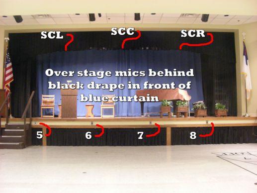
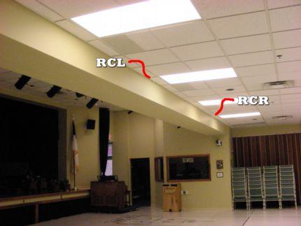
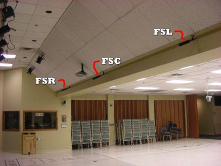
3 Basic Microphone Setup Follow these instructions for sending microphone output to the ceiling speakers. (Do all steps shown in green!) Turn on Main Amplifier power. The Main Amplifier power switch is located under the TV monitor on the rack on the sound booth west wall. Turn on sound board power Use the power strip switch below the stage light fader. Turn on power for any required wireless microphones receivers. (Note power strip above receivers.) Check the program request form for the number and placement of microphones. Place microphones. (Last page of this section has mic location pictures.) Make a note of the microphone connector number that corresponds with each sound board volume slider number. REMINDER Cover all exposed microphone cables with the rubber floor mats stored on the shelves found in the Sound Booth entry way to prevent tripping accidents. Page 1


4 Basic Microphone Setup Adjust ceiling speaker volume. NOTE: Speaker volume in the booth will sound louder than speakers in the auditorium. Check speaker volume outside of the booth. Set ceiling speaker volume slider at level U (the thick horizontal line) as a starting position. Do a volume check on all microphones. NOTE: There is a MUTE button near the top of each microphone volume slider. When the mute button is pressed, a red light will appear. All microphones should be muted except the one(s) in use. Near the bottom of the slider for each of the 24 channels, there are 3 ASSIGN buttons. For normal use, all three buttons should be pressed down except for the 1-2 buttons for the over the audience mics RCL 17 & RCR-18, and the Ceiling Front of Stage Mics FSL, FSC, FSR. Shut Down Turn off main power amplifier. Turn off remote microphones and receivers. Turn off Sound Board power. Disconnect and store microphones, cables, and cord covers. Check one more time to see that all equipment is off, then cover equipment with dust covers. Page 2
5 Basic Microphone Setup This version was created Saturday, September 22, 2012 Page 3
6 Basic Microphone Setup NOTES Page 4
 Place microphones as needed.")


7 Basic Program Setup Set Up Turn on power Turn on main amplifier power. (Use power strip switch at upper right corner of the amplifier rack.) Turn on monitor power strip. Turn on camera control power strip. Turn on Sound Board power. Turn on cameras. (The camera power switch is on the wall.) Place microphones as needed. Check the Program Request form for locations of required microphones. Make a note of the number of the microphone jack for each microphone in use. These numbers correspond to the sound board channel numbers. Cover exposed microphone cords with the rubber floor mats stored in the shelf found in the Sound Booth entry way. Do a volume check on each microphone. NOTE: There is a green light at the top of each microphone channel that indicates if phantom power is on. All green lights should be on at all times. Adjust volume using sound board Ceiling and Village speaker sliders. To prevent feedback only use the Front speakers when there are no microphones in the area in front of these speakers. Page 5


8 Basic Program Setup After the volume levels have been set, keep all microphone channels muted except the microphones currently in use. Adjust room lighting as required. Labeled If light switches are on the wall to the left of the sound boot door. stage spot lights are needed, consult lighting instruction sheet. Use the Sony Camera Control to Adjust Cameras Adjust cameras and set camera presets The camera controller has two rows of buttons. Buttons 1, 2 and 3 on the lower row are used to select a camera. Buttons 1 through 6 on the upper row will cause the selected camera to pan and zoom to a preset position. (Other camera and preset buttons are only available when different camera models are used with this controller.) Move the joystick left and right to pan the selected camera, move the joystick forward and back to tilt the camera, and twist the joystick handle to zoom in and out. In most situations the camera presets for each camera should be as follows: Preset 1, Lectern Preset 2, Wide view Preset 3, Piano Preset 4, Audience To move a camera to a preset position, press the Camera Select button, and then press the desired Preset button. Example for changing a preset: To adjust the preset for camera 3 for a wide view of the stage, select the Camera Select button 3, adjust pan and zoom for the wide view, hold the preset button down, and then press the Preset Select button 2. The camera monitor will briefly show a message that the preset has been accepted. Page 6 set

9 Basic Program Setup Use the Edirol camera mixer to switch between cameras For a smooth transition between camera shots, use the A-B T-bar slider on the Edirol. You can manually control the dissolve speed with the slider. There are two rows of buttons on the Edirol mixer, A and B. Buttons 1, 2, and 3 correspond to the 3 cameras. Button 4 is used to send the picture from the switcher (JVC or Sony video player or computer) to channel 99. There is a T-bar slider that can be moved from position A to B. If The camera 1 button is selected for the A position, and the T-bar slider is in the A position, the picture from camera 1 will be sent to the program (channel 99). If camera 1 is set to A and camera 2 is set to B, moving the T-bar from A to B changes the program picture from camera 1 to camera 2. NOTE: You can also change cameras by leaving the T-bar in place and pressing a camera button on that line. In this case, the Edirol knob marked Time will control the speed that the camera change is made. Before adjusting a camera shot, always make sure that the camera to be adjusted is selected on the side of the Edirol opposite the current program camera. In other words, do not adjust the camera that is being sent to channel 99 (unless you are intentionally moving the live camera shot). Otherwise, you will cause the channel 99 audience to become dizzy trying to follow your adjustments. Once the new camera shot is in place, use the Edirol to switch to that camera. The Wipe/PinP button on the Edirol can be used to create a mix of two cameras on the screen. For example, during a hymn the pianist can be shown in one corner of the screen while the audience is shown on the main screen. The knob marked Pattern on the Edirol is used to select the desired effect. If you want to try this effect, first practice the shots before the program. Then make notes about the A and B camera selections and the initial position of the slider. Using PinP during a program is a tricky option, but with a little practice and good notes about settings, you can pull it off. If the program is to be recorded, review the Recording Programs section of this manual. At the appointed program start time, switch the On Air light ON. Then switch the program switch to BVTV. Shut Down If the program was recorded, follow the instructions for finalizing a DVD (found in the recording instruction section), then remove and label DVD or tape from recorder. Turn off monitor(s) Turn off Sound Board Turn off Switcher Turn off main power amplifier Turn off DVD/VCR recorder Page 7
10 Basic Program Setup Disconnect and store all microphone cables and cord covers. Check one more time to see that all equipment is off, then cover equipment with dust covers. Check one more time to see that all equipment is off, then cover equipment with dust covers This version was created Saturday, September 22, 2012 Page 8


11 Recording Programs Turn on Video cameras and sound equipment following instructions found in the Basic Program Setup section of this manual. Turn on the JVC DVD/VCR Recorder. The lower left LCD monitor shows the video output from the JVC Recorder. This is what will be recorded. If the picture shown is not the same as the large monitor, try the following: Use the JVC Remote Control AUX button to set the input to AV1. Make sure that the small LCD monitor switch is pushed to the Video 1 position. Recording on DVD NOTE: We have had more consistent results with good quality DVD-R disks (as opposed to DVD+R, DVDRW, or DVD+RW disks). Insert DVD-R disk in JVC recorder. Wait for formatting to be complete. (Watch the display.) Be sure that the DVD option has been selected (see above). Approximately 2 minutes before the program starts, press the record button on the JVC recorder. At the end of the program, press the Stop button on the JVC recorder (this button is next to the REC button and has a small square symbol). NOTE: if the record button is pressed twice, the recorder will stop recording after the number of minutes shown on the display. Continue to press the record button until the number of minutes shown is greater than the expected program length. Page 9

 Approximately 2 minutes before the start of the program, press REC on the front of the JVC Recorder.")
12 Recording Programs After the recording has been stopped, the DVD must be finalized. Failure to finalize a disk will result in the disk not working on any player other than the Sound Booth Recorder. Follow the instruction found in the Finalizing a DVD section in this manual. Recording on video tape NOTE: When using tape, be sure that the tape has been rewound, and that the record protect tab has NOT been removed from the tape. Insert a video tape. Press the DVD/VCR switch until VCR is selected. (This switch is #13 in the following illustration.) Approximately 2 minutes before the start of the program, press REC on the front of the JVC Recorder. (Or use the REC button on the remote control.) When the program is complete, remove the VHS tape and label it with the program name and date. This version was created Saturday, September 22, 2012 Page 10
.")
 and press the Enter button.")

13 Finalizing a DVD-R disc If you are recording a DVD, the disc must be finalized before it can be played on any player other than the recorder. Use the following instructions to finalize the disc. To make the menus easier to read, switch the main monitor to B (JVC). Use the JVC Recorder Remote control to select the HOME button while the recorder is in Stop mode. Use the Recorder Remote to select Setup (Start) and press the Enter button. Use the Remote up and down arrows to move to the disk option and press the Enter (center) button on the remote. Use the remote arrow keys to select Finalize and press the Enter button on the remote control. When the display requests confirmation, select OK and press the Enter button on the remote control. Wait until the finalize process is complete. Switch the main monitor back to A. Remove and label the disc. Enrichment Hour disks should be placed in the Bristol Village Library. Page 11
14 Finalizing a DVD-R disc NOTES Page 12
15 Showing Videos on the Big Screen Set Up Lower Screen Check stage for obstructions. Press down switch on wall. (Move switch back to neutral after screen is down.) Turn on projector Use remote control, point at projector from on or near the stage and press the ON button, look for light in projector lens. The projector takes time to warm up. NOTE: If the projector is turned off, it cannot be turned back on until it has gone through a cooling cycle. It is possible to lock up the projector by attempting to turn it on before it has properly cycled. If this happens, refer to the Troubleshooting section of this manual. Turn on power Turn on main amplifier power. (Use power strip switch at upper right corner of the amplifier rack.) Turn on monitor power strip. Turn on Sound Board power. Turn on Atlona Switcher power, wait for all lights to stop flashing before selecting source button. Turn on Sony or JVC DVD/VCR Player Select the Sony or JVC button on the Atlona Switcher. Page 13
. Adjust room lighting as required.")
16 Showing Videos on the Big Screen Insert DVD or video tape into player Use the player remote control Drive Select button to select DVD or cassette. Play DVD or Tape (with some DVD's the remote control Menu button or the chapter jump >> button can be used to bypass previews). Adjust room lighting as required. NOTE: When the Switcher is in use, sound volume is controlled by the labeled channel on the sound board. Be sure the mute function is off on this channel. Also, be sure the Switcher is assigned to the Ceiling Speakers Adjust volume using sound board Ceiling and Front speaker sliders. (For movies, set front speakers a little louder than ceiling speakers.) Troubleshooting tip: If there is a picture, but no sound, try pressing a different button on the Switcher, and then select the player button again on the Switcher. NOTE: Either the Sony or the JVC can also be used to show programs on the big screen, however, the Sony seems to be more forgiving of poor quality disks. To use the JVC, follow the instructions above, only substitute JVC for Sony. However, If program recording is also required the JVC must be used as the recorder, and the Sony as the player. WARNING: loud feedback may occur when the player is stopped unless the Switcher volume control is on Mute. Shut Down Turn off projector Point the projector remote control at the projector and press the STAND-BY switch twice.(there will be a message on the projection screen when you press the POWER switch.) Raise Screen Return screen switch to neutral position after screen is all the way up. Turn off monitor(s) Turn off Sound Board Page 14
17 Showing Videos on the Big Screen Turn off Switcher Remove DVD or tape from player Turn off DVD/VCR Turn off main power amplifier Check one more time to see that all equipment is off, then cover equipment with dust covers. This version was created Saturday, September 22, 2012 Page 15
18 Showing Videos on the Big Screen NOTES Page 16


19 Projecting Computer Displays Setup NOTE: Mackintosh computers must have a VGA or HDMI adapter to work with our system. We do not supply this adapter. Lower screen Check for obstructions on stage. Press down switch on wall. (Move switch back to neutral after screen is down.) Turn on projector Use remote control, point at projector from near the stage, press ON button on remote, look for light in projector lens. The projector takes some time to warm the light, so wait for it. Follow Basic Program Setup instructions for turning on power. If the computer has an HDMI connector use it instead of the VGA/audio combination. A 25' HDMI cable is found in a box on the shelf above the power amplifiers. Connect computer RGB and Line audio to the wall panel below the sound booth window. The computer connection cable should be stored on a Presentation Station shelf. Use the 25 RGB cable to make connections from the computer RGB and Line audio out to the wall panel below the Sound Booth Window. Audio out from the computer will typically have a green connector ring. Most laptop computers have a function key option to switch between; computer LCD only, RGB out only, or both LCD and RGB. This is typically a toggle. Each time the function key is Page 17

20 Projecting Computer Displays pressed, the output display option is changed. Note that on some computers there is a several second delay for the display change to take effect after each toggle option is pressed. Turn on Switcher Wait until all lights on the switcher have stopped flashing before selecting any switcher buttons. Select Switcher Comp 1 for VGA connections. Select Switcher WALL for HDMI connections. Adjust room lighting as required. If computer audio is required, use the sound board Switcher slider to set the volume. Addendum - Sending a computer display to channel 99 The computer display (also the output from the DVD/VCR Player) is sent to channel 99 through the Camera 4 option of the Edirol Video Mixer. Turn on the Composite Converter. (This should come on when the Camera Control power strip is on.) This converts the switcher output signal to a composite video signal that can be used by the Edirol video mixer. Set switcher to COMP 1 (for VGA) or WALL (for HDMI). Use selection 4 on the Edirol mixer to send the image to the program video. Shut Down Turn off projector Point the projector remote control at the projector and press the STAND-BY switch twice.(a message will appear on the projection screen when you press the STAND-BY switch once.) NOTE: Pressing the STAND-BY switch once turns off the projector light, but keeps the fan running constantly. Be sure to watch for the message on the screen while turning off the Page 18

21 Projecting Computer Displays projector. Raise Screen Return switch to neutral position after screen is all the way up. Turn off power switches. Disconnect and store all microphone cables and cord covers. Check one more time to see that all equipment is off, then cover equipment with dust covers. This version was created Saturday, September 22, 2012 Page 19
22 Projecting Computer Displays NOTES Page 20


23 Audio-technica Wireless Microphone WARNING: The audio-technica wireless microphone has a mute option that can cause the microphone to appear that it is not working. Please review the following to learn how the mute option can be implemented and monitored. There is a difference between mics R1 - R2, and R3 R4. When R1 or R2 is turned on, a red light will appear on the transmitter (hand held or belt pack) will show that it is on. This light does not change when the mic is muted. When R3 or R4 is turned on, a green light will appear on the transmitter. When the mic is muted, the green light will change to red. Before using a wireless microphone, check the battery charge indicator (a horizontal dashes) in the receiver display. If the battery shows 1 or 2 bars, replace the batteries before using the microphone. Wait a couple of minutes after turning on the mic before checking the charge. A note about feedback. Feedback usually occurs when a microphone is picking up sound from a speaker. When the wireless microphones are in use they can be moved near one of the ceiling speakers. If the gain or volume is set too high, feedback may occur. If a wireless microphone is being used for audience questions, the sound board operator should closely monitor volume and mute the mic when it is not in use. It will be noticed that when a wireless mic is near the ceiling speakers, some echoing may be detected. WARNING: Putting your hand over a microphone will not stop feedback. In fact it will cause feedback. Wireless Receivers A power strip in the rack above the wireless receivers has a labeled switch for each receiver. Unless someone has turned off the switch on an individual receiver, only the power strip switch need be used. The audio-technica microphone system has a receiver and 3 possible microphones; hand held, lavaliere, or head-set. (Only one of the 3 microphone options can be used at a time with each receiver.) The receivers are located in the rack on the left side of the sound booth counter. Page 21


24 Audio-technica Wireless Microphone Hand held microphone The audio-technica wireless hand held microphone has a power/mute switch on the end of the microphone. This switch must be held on for a couple of seconds to turn on the microphone power. When the power on the microphone is on, a red dot will appear near the microphone LCD display and the receiver display will show a line of bars representing the battery charge state. When the power is on, a small LCD display on the microphone will appear. The receiver and microphone must be both set to the same frequency. Unless someone has messed with the frequency setting, the numbers displayed in both the microphone and receiver displays will be the same. NOTE: Once the microphone is on, each time the power/mute switch is pressed, the microphone status will be toggled between on and mute. If you have really good eyes, it is possible to see the word MUTE on the microphone LCD display when it has been toggled to mute. If the hand held microphone is either off or on mute, a red ALERT light will appear on the receiver. (This light takes a few seconds to appear after the microphone status has changed.) NOTE: Always inform the user that they should NOT turn the microphone on or off. Tell them that the microphone volume will be adjusted in the control booth so that when the microphone is not in use it will not transmit stray sounds. Lavaliere and Head Set The audio-technica microphone system has a remote transmitter pack that can have either a lavaliere or a head set microphone attached. To attach either the lavaliere or head-set, grasp the cord by the black section near the end of the cord. Insert the cord into the transmitter connector and rotate it until the cord snaps in place. To remove the cord, grasp the silver ring near the end of the cord and pull gently. Page 22

25 Audio-technica Wireless Microphone The audio-technica remote transmitter has a power/mute switch that is behind a sliding cover on the unit. The switch must be held down until the power comes on. When the power on the remote transmitter is on, the receiver display will show a line of bars representing the battery charge state. NOTE: The receiver and transmitter must be both set to the same frequency. Unless someone has messed with the frequency setting, the numbers displayed in both the microphone and receiver displays will be the same. NOTE: Once the microphone is on, each time the power/mute switch is pressed, the transmitter status will be toggled between on and mute. If you have really good eyes, it is possible to see the word MUTE on the transmitter LCD display when it has been toggled to mute. After the transmitter has been turned on, the sliding cover should be moved to protect the power/mute switch from accidental pressing. If the transmitter is either off or on mute, a red ALERT light will appear on the receiver. (This light takes a few seconds to appear after the microphone status has changed.) The wireless microphone volume should be tested by having the user speak normally. NOTE: Always inform the user that they should NOT turn the microphone on or off. Tell them that the microphone volume will be adjusted in the control booth so that when the microphone is not in use it will not transmit stray sounds. This version was created Saturday, September 22, 2012 Page 23
26 Audio-technica Wireless Microphone NOTES Page 24


27 Using Stage Speakers The stage speakers are used to provide audio to performers on stage who would otherwise not be able to hear other performers, CD audio, or themselves. The sound board provides a way to route specific microphones to the stage speakers. The volume for the stage speakers is controlled by knobs on each speaker and from a sound board volume control. This control knob is found on the right side of the sound board. Each microphone channel has a knob labeled Aux 1. The Aux knob controls the sending of microphone output to the Aux 1 Send Master (in our installation, the Aux 1 send master controls the volume of the stage speakers.) Stage Speaker Example 1 Here is an example of stage speaker use. Suppose that members of the chorus seated on the stage need to hear the speaker at the lectern. The stage speakers are positioned on the floor in front of the chorus and the control knobs on both speakers are set to level 8 The lectern microphone is connected to microphone input 5. The channel 5 Aux 1 knob is rotated to about half way as a starting point. With this setup, the volume from the lectern microphone to the stage speakers can be controlled by adjusting the Aux 1 knob on sound board channel 5 and the Aux 1 stage speaker volume knob. NOTE: To prevent feedback in the above example, do not position the stage speakers where they can send sound to the lectern microphone. Stage Speaker Example 2 Another example of using the stage speakers is when a vocalist is accompanied by the piano. In this example, one stage speaker is placed in front of the vocalist and a second stage speaker is placed near the pianist. Set each stage speaker volume control to level 8. Let's connect the vocal microphone to channel 6 and the piano microphone to channel 7. On the sound board, all Aux 1 control knobs are all set to 0 except channels 6 and 7 (which are rotated about half way as starting points). The stage speaker volume knob is set to 8 as a starting point. The sound board Aux 1 knobs are then used to adjust the desired stage speaker volume for each microphone. Page 25 1


28 Using Stage Speakers Stage speaker connections Stage speakers are connected to each other via cables with 1/4 inch phone jacks. Connect the out port of the first speaker to the in port of the second speaker. Connect the in port of the first speaker to a connector jack located on the lower right front side wall behind the stage curtain (as viewed from the audience). NOTE: There is a coat hook on the wall above the stage speaker connector jack that should be used for storing the stage speaker cables. Quick review Set the on-speaker volume controls to 8. Use the sound board Aux 1 control knobs to set volumes for the microphones to send to the stage speakers. Use the sound board Aux 1 send master knob to control the stage speaker volume. REMINDER: The stage speakers are typically used in conjunction with stand microphones that are placed on the stage floor. The floor is like a big drum that can transmit sounds up the microphone stand to the mike and cause unwanted sounds. When using a microphone stand on the stage, always place a piece of carpeting or other soft material under the microphone stand. This version was created Saturday, September 22, 2012 Page 26
 Turn on Sound Board power. (The sound board power switch is below the stage lighting fader controls.")

29 Playing CD's NOTE: Although both the Panasonic and Sony DVD Recorder/Players will play most CD disks, the Gemini CD player is the best choice for playing CD's Turn on power Turn on main amplifier power. (Use power strip switch at upper right corner of the amplifier rack.) Turn on Sound Board power. (The sound board power switch is below the stage lighting fader controls.) Turn on Gemini CD player power. The CD power switch is on the strip of switches above the CD player. If the Pitch button is ON, push it to turn this function OFF. NOTE: Do not push on the CD drawer to close it. This can cause damage. Only use the Eject button to open and close the drawer. Press the Eject button to open the CD drawer. Insert CD into Gemini CD player, press the Eject button to close the drawer. Page 27


30 Playing CD's Select CD track. There are two buttons that move track selection forward or backward. The current selected track appears on the LCD display. Track selection Before playing the CD, you should decide how it is to be used. Two possible options are: playing a single track and stopping, or continuous and/or repeat play of the entire CD. To play a single selection: Select the desired track. Press the Single button until the word Single appears on the LCD display. Press the Time button to select the desired time display option; time elapsed for the track, time remaining for the disc, or time remaining for the track. Press the Play button and adjust the sound levels (see Setting sound levels section below). When the desired sound levels have been set, press the Cue button to pause the CD at the beginning of the track. Page 28

31 Playing CD's NOTE: Pressing the Cue button during playing returns the player to the start of the selected track and pauses until the Play button is pressed. Setting sound levels There is a slider on the sound board that controls the volume of the CD player. There is also a volume knob on the CD player itself. Set the CD to the desired track and press the Play button. Set the volume of the Ceiling and/or Front speaker sliders to the U position. Set the volume slider for the CD Player to the U position and then fine tune as required. If necessary, use the volume knob on the CD player to obtain the desired level. NOTE: The front speakers should not be used if there are any microphones in the area near the front speakers. When the desired volume is set, press the Cue button to return to the start of the track and wait for the appropriate time to play the selection. Play CD The Play button is also a Pause button. Press it once to play, press it again to pause, press it again to play. NOTE: If the Single option is ON (see above), the player will stop at the end of the selected track. To play a complete CD: Select Press track 1. the Single button until the word Single disappears from the LCD display. Press the Time button to select the desired time display option; time elapsed for the track, time remaining for the disc, or time remaining for the track. Press the Play button and adjust the sound levels (see below). When the desired sound levels are set, press the Cue button to pause the CD at the beginning of the track. Page 29
32 Playing CD's If you want to have the CD repeat after playing all tracks, press the Repeat button until All appears on the LCD display. Play CD Shut Down Turn off monitor(s) Turn off Sound Board Remove CD from player Turn off CD player Turn off main power amplifier Check one more time to see that all equipment is off, then cover equipment with dust covers. This version was created Saturday, September 22, 2012 Page 30


33 Vespers Pre/Post Show When the big button is pressed to send Vespers to channel 99, there is typically no transition between whatever CD is being played from the information display in the Administration Building and Vespers. This means that the audience goes from random music, perhaps a jazz or big band vocal arrangement, directly to Vespers. The same is true at the end of Vespers. The viewer may be faced with jumping directly from the benediction to loud raucous music. In order to provide a smoother transition between Vespers and the CD of the day, several DVD volumes of pre and post Vespers programs have been prepared. Each DVD volume contains one pre and one post Vespers video program. The following section describes how to use these programs. Pre-Vespers Show Set up the audio visual equipment for a normal Vespers program. Turn on the Sony player and insert a Vespers pre/post DVD. Make a note of the program length. Programs on the different DVD volumes have different lengths. Turn on the Atlona Switcher, wait until it has finished its setup routine, and select the Sony player button. Note that with the Switcher and the video converter on, the device selected on the switcher (JVC recorder, Sony player, or Computer) will be available as Camera 4 on the video mixer. NOTE: When the Sony player is put on Pause, it will automatically start playing in 5 minutes. Therefore, do the next step less than 5 minutes before the pre-show is to start. Use the Sony remote control to select the pre-vespers program. Press the Play button the Sony remote control and as soon as the program starts to play, press the pause button on the remote control. Set the volume control for the Switcher to a nominal level. NOTE: Normal Vespers operation is to send the DVD program audio to only channel 99. To send audio from the DVD only to channel 99, toggle the sound board Page 31
34 Vespers Pre/Post Show Switcher audio channel Assign 1-2 OFF (It is off when it is UP). At this point, the Sony monitor should show a picture from the beginning of the DVD program. When the channel 99 switch is pressed for the pre show, do NOT turn the On Air light. At the appropriate time before Vespers, use the Mixer to select Camera 4. Switch the channel 99 button, and press Play on the JVC remote control. When the program is done, mute the Switcher audio, turn on the On Air light, and use the Mixer to select the desired camera. Post-Vespers Show Use the Sony remote control to select the post-vespers program. NOTE: When the Sony player is put on Pause, it will automatically start playing in 5 minutes. Therefore, do the next step less than 5 minutes before the post-show is to start. Press the Play button the Sony remote control and as soon as the program starts to play, press the pause button on the remote control. When the Vespers service is over, use the Mixer to switch to Camera 4. Turn off mute for the Switcher audio. Press Play on the Sony remote control. This version was created Saturday, September 22, 2012 Page 32


35 Sound Booth Speaker, and Audio Assignment Buttons Assign button background information Every column of inputs on the sound board is identical. If you know how to adjust one microphone input you know how adjust 22 inputs. Near the bottom of each input column are 3 assignment switches. These are toggle switches, one push locks them in, another push locks them out. The top assignment switch is labeled 1-2, the middle is labeled 3-4, and the bottom is labeled Main Mix. In the speaker volume control area on the right side of the sound board, the sliders are labeled 1, 2, 3, 4 and Main Mix. When an assignment button is down, the sound from that microphone WILL be sent to the speakers in the assigned group. When an assignment button is up, the sound from that microphone will NOT go to that group. In normal situations, all assignment buttons should be down EXCEPT the group 1-2 buttons for the over the audience microphones and the front of stage ceiling microphones. This means that the sound from the over the audience microphones will not be sent to either the front or ceiling speakers (which are connected to outputs 1 and 2). If the assignment buttons for the ceiling microphones are down there will be loud feedback. When a Vespers pre or post video is being played on channel 99, the Vespers Committee has requested that the sound from the program not be heard in the room. In this case, the Group 1-2 assignment button for the Switcher can be toggled to the up position to prevent the audio from the DVD Player from being carried on the ceiling speakers. The Switcher assignment button must be down when DVD movies are being played. Sound Booth Speaker Volume In July of 2009 a new speaker was added to the sound booth. This speaker reproduces the exact mix of sound that is going to the Village on Channel 99, and that is being recorded on the JVC recorder. This speaker was added to address the issue of the ceiling speaker in the sound booth not adequately monitoring program sounds. The sound booth speaker is connected to the #4 volume control slider. This means that this speaker carries the sound from all inputs that have their Assignment 3-4 buttons in the down position. This should include the over the audience microphones. This allows the operator to monitor the sound level for hymn singing or applause. NOTE: Sound from the over the audience microphones is not heard on the ceiling speaker in the sound booth because their Assignment 1-2 buttons are in the up position. Without the booth speaker, some operators have set the audience microphones too loud because they could not hear the audience from the booth ceiling speaker. Page 33
36 Sound Booth Speaker, and Audio Assignment Buttons (At some point, the ceiling speaker in the sound booth may be disconnected.) Proper volume of the ceiling speakers in the auditorium can only be judged from outside the sound booth. This version was created Saturday, September 22, 2012 NOTES: Page 34
37 Stage Lighting NOTE: Stage lighting was completely re-worked in July of There are 24 lights that can be controlled using the Smartfade control board. The following illustration shows the position of these lights. Power on/off NOTE: It is no longer necessary to use the main circuit panel breakers to supply power to the stage lights or Smartfade controller. NOTICE: The power strip below the counter must be turned on to supply power to the Smartfade control board. Also, if the power switch is held down for more than 5 seconds when the system is being turned on, the default mode option display will come on. If this happens, use the wheel to select Two Scene mode. To turn on the Smartfade power, press the on/off button. If the Smartfade does not start in Two Scene Mode, the power must be turned off and the Smartfade must be restarted. When the power is turned back on the power switch must be held down for more than 5 seconds. The wheel is then used to select Two Scene Mode. To turn off the Smartfade power, first press the black out button to turn off all lights, press the on/off button, and then press the P button to confirm. Using the Smartfade control system. Light controls on the Smartfade board are assigned to 24 lights as shown in the following illustration. Page 35

38 Stage Lighting Stage Lights Smartfade lights are shown in red Stage lights A light bar containing 6 spot lights is mounted in front of the stage. Two spot lights are mounted on the ceiling near the sound booth. Eight spot lights are mounted above the stage. Two colored light strips with 4 colors each are mounted over the stage. The Smart fade control board on the counter near the sound booth door controls these 24 lights. There is a set of 6 work lights mounted over the stage. These are controlled either by wall switches in the sound booth or by wall switches near the stairs that lead to the rear of the stage. There are 3 fluorescent lights over the rear area of the stage. These are controlled by a wall switch in the sound booth. Lights 1 and 2 are for lighting a presenter located in front of the stage during power point or other presentations that use the projection screen. (The Presentation Station should be positioned near #10 on the shuffle board court nearest the sound booth.) Lights 3 through 7 are located on a light bar in front of the stage. These are used to light typical stage programs. Lights 4 and 7, together with the back light 13, are used to illuminate the lectern when it is placed on the marks on the left side of the stage. This is a typical Vespers arrangement. Lights 3, 5, 6, and 8 are used to illuminate different parts of the stage. Light 13 is used to back light on-stage presenters who are using the lectern when it is located to the left front side of the stage (for Vespers and other similar programs). Lights 9 through 16 are located over the stage. Light 9 is used for the piano when it is on the right side of the stage (as viewed from the audience). Lights 10, 11, and 12 illuminate the front portions of the stage. Lights 14, 15, and 16, illuminate the area behind the blue curtains and are used to light groups on the risers. Page 36


39 Stage Lighting The over stage colored lights are in two banks, 17 to 20 and 21 to 24, near the rear of the stage. These are used to provide a colored backdrop for programs. Using the Smartfade in two scene mode. The most direct and simple application of the Smartfade control board is when it is set in two scene mode. Actually, to make things even simpler, when the Smartfade is in two scene mode, only one scene needs to be used. The Smartfade control board has 2 sections of 24 sliders each labeled A and B. The light control board can be set to operate in a fashion similar to the camera mixer. The camera mixer has an A side and a B side along with a T-bar that is used to change the active camera from the A setting to the B setting. Similarly, light settings can be changed from the A settings to the B settings by moving the A-B cross fader controls together. The trick is to set the A sliders to the first desired light setting and the B sliders to the second desired setting. When the A-B sliders are moved together, the lighting will change from the A settings to the B settings. In the illustration, the crossfaders have been moved to the upper position. Close examination of the number scale along the cross fader slider paths will show that in this position A is at 0 and B is at 10. The illustration shows the B light controls have the sliders for front spots 3 through 8 turned on full, and the A sliders off. In this situation, moving the cross fader sliders downward from the position shown will dim lights 3 through 8 from full to off. NOTE: There is a time delay setting (shown in the LCD panel) that controls how fast the lighting change takes place after the cross faders have been moved. Page 37

40 Stage Lighting Example Practice Set up Turn off stage and room lighting. Set the crossfader pair to the top position, then set the B faders smiler to the illustration above and observe the lighting effects. Set the A faders all to 0. Move the A_B crossfader pair up and down to switch between spots on and off. Use the Lighting Worksheet The Lighting Worksheet makes it easy to set and record program lighting. Worksheets can be saved for reference for future programs. Power Off To turn off the Smartfade power, first press the blackout button, press the power button, and then press the P button to confirm. If you do not press the Blackout switch before turning the power off, the spot lights will stay on. This version was created Saturday, September 22, 2012 Page 38

41 Camera Controls This section describes how to Pan, Tilt, and Zoom the cameras and how to adjust the various camera settings using the Sony RM-BR300 controller. Using the Sony Camera Control The camera controller has two rows of buttons. Buttons 1, 2 and 3 on the lower row are used to select a camera. Buttons 1 through 6 on the upper row will cause the selected camera to pan and zoom to a preset position. (Other camera and preset buttons are only available when different camera models are used with this controller.) Observe the 3 small monitors labeled Camera 1, 2, and 3 as you perform the following steps. Select the Camera 1 button on the lower row of Camera Select buttons. Move the joystick left and right to pan the camera. Move the joystick forward and backward to tilt the camera Twist the joystick clockwise and counter clockwise to zoom in and out. Practice pan, tilt and zoom until you can easily move the camera to a target. Repeat the above steps for each of the three cameras. There are 6 preset camera positions available. Do the following steps to save a camera preset. Adjusting Presets Select the Camera 1 button on the lower row of Camera Select buttons. Adjust the camera to focus on the Lectern. Locate the Camera Control button labeled Preset and while holding it down press the #1 Preset select button. NOTE: When the preset is successful, the monitor will briefly display the message PRESET 1 OK. Page 39

42 Camera Controls Adjust the camera to focus on a new location. Press the Preset 1 button to have the camera automatically return to the preset shot of the lectern. Repeat the above steps for Cameras 2 and 3. NOTE: A Camera Preset Worksheet is available for recording the preset locations. In most situations the camera presets for each camera should be set as follows: Preset 1, Lectern Preset 2, Wide view Preset 3, Piano Preset 4, Audience (not available for camera 2) Preset 5 and 6, optional By standardizing the presets for all cameras, you will have fewer things to remember during a program. During program setup, Adjust a camera to a preset position, press the Camera Select button, and then set the desired Preset. Example for changing a preset: To adjust the preset for camera 3 for a wide view of the stage, select the Camera Select button 3, adjust pan and zoom for the wide view, hold the Preset button down, and then press the Preset Select button 2. The camera monitor will briefly show a message that the preset has been accepted. The above process describes how to adjust and save the camera position and zoom settings. The camera presets also can save other camera settings. Using Camera Control Menus The Camera Control Menu system provides access to a large number of control settings. Most of these are not commonly used, however there are two areas that affect the quality of video for Channel 99 broadcasts. Select a Camera using the Camera Control. Press the Preset #1 button to focus on the lectern. To access the Camera Control Menu, press the Menu button on the Camera Control. You may have to hold the button down for a second for the menu to appear. This places the Menu on the monitor display. The illustration shows 6 menu options. The two options to be discussed are WHITE BALANCE and EXPOSURE. A > character appears on the left side of the current selected menu option. The illustration shows the > character at the EXPOSURE option. To move the menu selection character, move the joystick forward and backward. Page 40


43 Camera Controls Setting WHITE BALANCE Options Use the joystick to move the selection character to the WHITE BALANCE option. With the selection character at the WHITE BALANCE option, press the button on the end of the joystick to open the WHITE BALANCE sub menu. To switch between the WHITE BALANCE MODE options, move the joystick left and right. Move the joystick left or right until the WHITE BALANCE INDOOR option is selected. NOTE: the settings are stored with each preset. The WHITE BALANCE will have to be set separately for every camera preset. Locate the Camera Control button labeled Preset and while holding it down press the #1 Preset select button. Observe that Preset #1 has been set to OUTDOOR for Camera 1 and INDOOR for Camera 2 in the illustrations. NOTE: Pressing the MENU button on the Camera Controller will back up one menu level. You should check to insure that the WHITE BALANCE is set to INDOOR for all camera presets. Using Manual EXPOSURE Options When the camera is focused on a scene that is generally uniform in lighting, for example panning the audience, the full automatic exposure option will yield acceptable results. However, when the stage spotlights are in use, and the lighting contrast varies across the scene, the automatic exposure feature of the cameras will probably not provide the best video picture. For example, if the camera is focused on a speaker at the lectern surrounded by dark curtains. In these cases, manual exposure controls will dramatically improve the picture. NOTE: Pressing the MENU button on the Camera Controller will back up one menu level. Select a Camera using the Camera Control. Press the Preset #1 button to focus on the lectern. To access the Camera Control Menu, press the Menu button on the Camera Control. You may have to hold the button down for a second for the menu to appear. Use the joystick to move the selection character to the EXPOSURE option. With the selection character at the EXPOSURE option, press the button on the end of the joystick to open the EXPOSURE sub menu. Page 41

44 Camera Controls To switch between the EXPOSURE options, move the joystick forward and backward. With the EXPOSURE MODE option selected, move the joystick left and right until the FULL AUTO mode is selected. Move the joystick forward and backward until the EX COMP (EXposure COMPensation) option is selected. Move the joystick left and right until EX COMP is ON. Move the joystick forward and backward until the LEVEL option is selected. Move the joystick left and right to change the LEVEL. (Observe the picture on the monitor to determine when the exposure compensation is acceptable.) NOTE: Unless the POS options are changed, the camera sensors take readings from the center of the view. If the exposure compensation is set when a bright area is in the center of the view and the camera is then moved to a place where a dark area is in the center of the view, the exposure compensation will be incorrect. When the monitor shows a properly exposed picture, hold the Preset button down and, while holding the preset button down, press the current preset selection button. The current MENU settings, EXPOSURE, WHITE BALANCE, and others will be stored with the current camera preset. This means that if manual exposure settings are to be used, they will have to be adjusted and memorized for every camera preset for each camera. To turn off the MENU, press the MENU button. Backlighting the Speaker When a speaker is at the lectern, and when the lectern is positioned at the marked location to the right of the stage (as viewed from the audience), the video picture of the speaker will be improved by adding back lighting. This is done for the standard lectern position through the use of light #13. The illustration shows the difference adding 50% of light #13 makes to the picture. Adding back lighting adds a bit of professionalism to broadcast images. This version was created Saturday, September 22, 2012 Page 42

 on the switcher. Use the player remote to select the desired text. The text DVD includes chapter stops.")

45 Superimposing Text The Edirol camera mixer is capable of superimposing or merging images. A DVD is available that has text displayed on a black background. The text includes things like Enrichment Hour will start at 7:30, or This has been Enrichment Hour at Bristol Village. To superimpose the text over a camera scene, use the following procedure. NOTE: Either the JVC or Sony can be used. However, since the JVC is typically used for recording, these instructions will be based on using the Sony player. Insert the DVD containing the text into the player. Select the player (Sony) on the switcher. Use the player remote to select the desired text. The text DVD includes chapter stops. This means that the remote can be used to jump to different text sections on the disk by pressing the NEXT or PREV buttons on the remote. When the desired text section of the DVD is on the screen, press the pause button on the player remote. NOTE: When the Sony is in pause mode, it will automatically start playing after 5 minutes. Try to make sure that the time for superimposing text is less than 5 minutes. Otherwise pressing Play-Pause will reset the timer. Move the Edirol camera mixer T-bar to the B (lower) line. Select the desired camera shot on the Edirol camera mixer B line. (The illustration shows camera 3.) Select camera 4 (AUX) on the Edirol camera mixer A line. Press the SUPERIMPOSE effects button on the Edirol camera mixer. Move the Edirol camera mixer T-bar to the A position. It may me necessary to use the KEY LEVEL knob to adjust the superimpose value. To exit text superimpose mode, move the Edirol camera mixer T-bar to the B position. Press the SUPERIMPOSE effects button on the Edirol camera mixer to turn off the effects. This version was created Saturday, September 22, 2012 Page 43
46 Superimposing Text Notes Page 44


 icon. After selecting the star (Favorites) icon a new list of options will appear.")


47 Copying a DVD Using Nero Computer Software The Sony recorder and Panasonic player located in the sound booth can be used to make a video tape copy of a DVD or to make a DVD copy from a video tape. (NOTE: copies can only be made from locally produced programs. Commercial tapes and DVD's are typically copy protected.) If it is required to copy from a DVD to another DVD, the Sight and Sound computer can be used. NOTE: It will typically take a little longer than the original program length to make a copy. Start the computer and double click on the Nero Set Smart shortcut icon found on the Desktop. When the Nero welcome window appears, select the star (Favorites) icon. After selecting the star (Favorites) icon a new list of options will appear. One of these options provides for copying DVD's From the Nero window, select the Copy DVD icon. Selecting the Copy DVD icon will open the Nero Express Essentials dialog box. This dialog box provides options for selecting source and destination drives. In our case, there is only one drive available, so the default settings can be used. Place the DVD to be copied in the drive. (There is a button near the lower right corner of the drive, located near the top of the computer case. Push this button to open or close the drive drawer.) From the Nero Express Essentials dialog box, select the Copy button. The burning process will now start. The computer will copy the contents of the DVD onto the computer hard drive. The Nero Express Essentials dialog box will monitor copy progress. Page 45


48 Copying a DVD Using Nero Computer Software When the contents of the source DVD have been copied to the computer hard drive, a Waiting for Disc dialog box will appear that prompts you to remove the source disk and insert a blank disk. Remove the source DVD, insert a blank DVD, and press the button to close the drive. The Nero Express Essentials dialog box will continue to monitor the copy progress. The total time for copying will vary with the length of the original program. When the copy is finished the Nero Express Essentials dialog box will show if the process is successful. When the copy is finished, select the Next button in the Nero Express Essentials dialog box. Nero Express Essentials will provide options for burning another DVD or for saving the current project. When you have finished burning DVD's, remove the DVD, close the drive drawer, and close the Nero program. (To close the program, select the X in the upper right corner of the Nero window.) This version was created Saturday, September 22, 2012 Page 46
49 Atlona Display Settings for Projecting Computer People bring in a variety of different brands of computers for displaying on the big screen. This document discusses some of the issues involved. Computer outputs Laptop computers have two types of video outputs, VGA and HDMI. Of the two, HDMI is preferred. VGA connections require a separate cable connection for audio, while HDMI cables pass both the video and audio signals to the Atlona switcher. We have the two types of connections on the wall plate below the Sound Booth windows. Inside, on the Atlona switcher, the VGA input from the wall plate is labeled COMP 1, while the HDMI connector on the wall plate is labeled WALL. There are additional computer connections available inside the Sound Booth. Cables behind the DVD players are labled for HDMI 2 and COMP 2 and COMP 3. There are times when it is desirable to use a computer inside the booth for either projecting on the big screen, or for sending displays to BVTV. Some limited research shows that at least some laptops will default to a resolution of 1024x768 when connected to an external monitor through the VGA connector. The HDMI connection, however, seems to preserve the native resolution of the computer. Desktop computers can also be connected to the Sound Booth system. However, to see images on both a desktop monitor and the big screen, a VGA splitter box is required (unless the desktop computer has a separate HDMI connector). A VGA splitter box is available in the Computer Room Workshop. Resolution Issues Some computers have been found to have poor or ragged displays when sent to the big screen. The Atlona switcher has a menu system (which is accessed through buttons on the front of the Atlona) that provides a number of resolution options. The on-screen display also includes a NATIVE option. When the menu button is pressed on the Atlona, an on-screen display appears. Pressing the + or buttons on the Atlona moves the cursor over the different menu options. Pressing the Enter button on the Atlona selects the next menu level, or the selected option. The OUTPUT options are shown above. Page 47
50 Atlona Display Settings for Projecting Computer The following table shows the result of experiments with two different laptop computers. The first is Louie 1 that has a native resolution of 1280x800, but that automatically changes to 1024x768 on both the laptop screen and the VGA output when an external VGA cable is in place. The second is Louie 2 that has a native resolution of 1600x900 that is preserverd on the laptop display when an HDMI connector is in place. Resolution Louie 1 (VGA, 1024x768) Louie 2 (HDMI, 1600x900) WXGA (1280X800) OK POOR WSXGA (1680X1050) OK POOR WUXGA (1920X1200) OK OK WUXGA (1440X900) OK OK 1080@30hZ OK OK NATIVE OK OK The moral of this story is that if someone brings in a laptop and the display on the big screen looks ragged and unpleasant, you can try changing the resolution selected in the Atlona switcher. Occassionally during this experiment, a good image would appear on the big screen, but nothing would appear in the booth. The solution to this problem seemed to be to change the Atona and the video mixer to a different source, change the resolution, and then return to the computer source. A work around, and a method that works when the presenter is projecting text or images that are small, is to point camera 2 at the screen and zoom in as required. This version was created Saturday, September 22, 2012 Page 48
51 Troubleshooting Projector Use the remote control to turn on the projector. The remote has to be pointed directly at the projector from near the stage. The remote does not work from inside the sound booth. If projector does not go off. Point the remote at the projector and press the STAND-BY button twice. The first press will display a message on the screen. The second press will turn the projector off. Note: Projector power is controlled by breaker #11 on Power Panel #1 (back of stage). If the projector fails to come on (a green light on the projector may be flashing on and off in a sequence of flashes), the projector may have to be reset by turning off it's power for a few minutes. When the power is restored, the projector will take a minute or so to reset before it can be turned on. If a video does not project. Videos are played from the JVC or Sony player. Select the proper drive (DVD, VHS). Check to make sure the picture appears on the LCD monitor for the player. Make sure the Switcher is on, and the proper player button is selected. If a computer does not project: Make sure that the VGA (or HDMI) cable is connected from the computer to the wall jack below the sound booth windows Make sure the Atlona Switcher is on, and the Comp 1 (for VGA), or WALL (for HDMI) button is selected. Set the computer video toggle to display both LCD and VGA. (this setting is unique to each computer. Most laptops have an extra function key marked Fn that has to be pressed together with a second function key, for example Fn+F5.) If the computer display on the projection screen is off center: Make sure that the computer resolution is set to 1024x768. (Right-click on a Windows computer desktop, select Properties, Settings.) 16:9 or 4:3 aspect ratio? Some (typically older) movies and computer displays are designed for a 4:3 aspect ratio. Newer videos and computer displays are designed for 1a 6:9 aspect ratio. If the projected display falls off the bottom of the screen (when using a computer) or has squashed fat or stretched skinny people in videos, the projector aspect ratio may have to be changed. This required use of the full projector remote control stored in a sound booth drawer. To change the aspect ratio, press the Menu button on the projector remote (there are two computer remote controls, one has on-off only, Page 49

52 Troubleshooting the other, kept in a drawer, has menu functions) and then locate the appropriate menu option. If there is a picture on the projector, but no sound, try a different source button, Sony, JVC, etc., and then re-select the desired source button. (When the Switcher is turned on you must wait for a setup sequence to be completed before you press any buttons. If a selection is made before the switcher has completed the start up process, audio may not follow video. The setup sequence is complete when an indicator light is on steady.) Make sure that the Switcher Assign buttons on the sound board are set correctly. Audio Problems No Sound. Check to make sure that the amplifier rack power is on. (If the amplifier rack power strip light does not come on, it is possible that the circuit breaker has been overloaded. You can check by plugging a working lamp into the wall outlet behind the amplifier rack. If there is no power, check Breaker #12 on the left panel on the rear wall of the stage.) No Sound. Make sure that all speaker amplifiers are turned on. No Sound. If the sound board power is on, check the speaker volume sliders and mute buttons. No Sound. If there is no sound from a particular mic or input, check the assign buttons. Bad Loud Feedback. QUICK, punch MUTE buttons. Bad Loud Feedback. Feedback usually comes from a speaker sending sound to a microphone. If the ceiling room microphones assignment buttons Group 1-2 are down, feedback is guaranteed. Bad Loud Motorboat Feedback. This will happen if the JVC recorder/player is stopped when the Switcher audio line is not muted. If some microphones work, but others do not: Page 50


53 Troubleshooting Check mute buttons. Check assignment buttons All assign buttons should be down except for the ceiling room microphones. The room ceiling microphone Group 1-2 buttons should be up, all other assignment buttons should be down. Check phantom power (all green lights along the top of the sound board should be on.) For remote wireless microphones: Check that wireless receiver power is on. Check transmitter or hand microphone batteries. Check that the transmitter or hand microphone is not on mute. Note: Once the wireless 1 or 2 remote transmitter or microphone has been turned on, each time the power button is pushed it will switch the mute option between on and off. The word mute will appear in microscopic letters on the microphone display. If two red lights appear on the remote receiver (R1 through R4) it means that either that that microphone is muted or that its battery is dead. No sound from wireless mic, but battery check is good, mute is off, and power is on... Check to be sure the frequency address shown in the receiver transmitter are the same. and The Sony player (or JVC Recorder) is playing strange music over the ceiling speakers. Mute the Switcher on the Sound Board. Change the TV channel to channel 1. There is a strange sound echo in the booth. Turn off the small recorder monitor speaker above the JVC and Sony recorder/player. If stage speakers are not working: Make sure speakers are connected to ¼ inch jack on inside right wall of the stage (as viewed from the audience). Check audio level knobs on speakers. (A setting of 8 is typical.) Adjust Aux 1 knob marked Stage on sound board. Adjust Aux 1 knob for each microphone that is to be sent to the stage speakers. Make sure that the stage speaker amplifier (on the main power rack) is on. Video tape or DVD video is playing, it is visible on the big screen, but there is no sound. Check sound board channel for volume or mute. On the switcher, select a different source button... then select the DVD/Video button. Unwanted sound in the Cafe, Page 51
.")
54 Troubleshooting The switch for controlling the Cafe speakers is located in the maintenance office near the bank. It looks like a typical wall switch and is located near the PA system over the desk. Video Problems No picture on JVC recorder LCD monitor screen: Check JVC recorder power. Set JVC recorder input to Aux (use the recorder remote control). Note: If the sound board audio volume slider for recording is not up, no sound will be recorded. No picture from cameras: Check camera power switch (high on wall to the right of the camera controller). Check individual LCD monitor toggle switches. No picture on Camera 4: Note: Camera 4 (on the video mixer) is set to display whatever is selected on the Switcher This means that if a computer display (or whatever) is on the Switcher monitor, it can be sent directly to channel 99 by setting the mixer to camera 4. In order for this to work, both the Switcher and the converter box (on the Switcher) have to be turned on. The converter box power should come on with the camera control power strip. Presets on the Camera Controller do not work. Check the Shift Light on the Camera Controller. If the lower light is ON, press the Shift button for 1 second to change it to the upper position. Camera Controller stops working. Turn off power to controller, wait 30 seconds, turn power back on. Lighting changes as presenter at lectern moves around. Page 52 If the camera exposure is set to FULL AUTO, the camera will try to adjust the lighting at the lens target. If the presenter moves so that the center of the frame contains different brightness levels, the exposure will change. To overcome this issue, set the camera exposure compensation on. (see Camera Controls section of this manual)
The Illustrated manual for. Halsey 107 & 109
 The Illustrated manual for Halsey 107 & 109 Contents The control panel... 1 Microphones... 3 Screens...6 Lights...7 Computers... 8 Connecting a laptop or roll-around computer... 10 Videocassette recorder
The Illustrated manual for. Clow 103
 The Illustrated manual for Clow 10 Contents Lights...1 Turning on the system... Microphones... 4 Turning the video projector on and off... 6 The screen... 7 VHS videocassette recorder...8 Computer... 10
Halsey 106. For assistance and additional equipment, contact Halsey Instructional Technology Services Halsey 259, extension 4979
 The Illustrated manual for Halsey 106 Contents The master power switch...1 Screen...3 Turning on the projectors...4 Turning off the projectors...5 Microphones... 6 projectors... 9 Installed Computers...
Classroom Setup... 2 PC... 2 Document Camera... 3 DVD... 4 Auxiliary... 5
 Classroom Setup... 2 PC... 2 Document Camera... 3 DVD... 4 Auxiliary... 5 Lecture Capture Setup... 6 Pause and Resume... 6 Considerations... 6 Video Conferencing Setup... 7 Camera Control... 8 Preview
Electronic Equipment Manual For 101, 102, 301 & 302 Azrieli Theatre For further information, please visit our website at:
 Electronic Equipment Manual For 101, 102, 301 & 302 Azrieli Theatre For further information, please visit our website at: http://www.carleton.ca/ims/ 2 TABLE OF CONTENTS: Topic Page # Logging onto the
Saint Joan of Arc Tech Ministry. St Expedite Patron Saint of Nerds (Updated 19 April 2014)
") Saint Joan of Arc Tech Ministry St Expedite Patron Saint of Nerds (Updated 9 April 204) Camera Operations (Commons & Worship Space). Power ON camera (closet in commons/worship space {turns on power & fan
Saint Joan of Arc Tech Ministry St Expedite Patron Saint of Nerds (Updated 9 April 204) Camera Operations (Commons & Worship Space). Power ON camera (closet in commons/worship space {turns on power & fan
Contacts: English Department Office 238 Moreland Media Services 109 Kidder
 Contacts: English Department Office 238 Moreland 7-3244 Media Services 109 Kidder September 2006 Welcome...3 Starting Out...5 Unlocking the Station...5 Touch Panel Operation...5 Projector...6 Selecting
Service FOR SERVICE. Quick Reference Guide. Page 23. Contact your help desk at
 Service Page 2 FOR SERVICE Contact your help desk at Quick Reference Guide 0 Judson Street, Unit 5 Toronto, ON M8Z 5T6 Tel: -800-652-266 www.adcom.ca Copyright 2004 Power Source Page 22 UPS Connect the
LAVALLEY LAW LIBRARY MEDIA SERVICES INSTRUCTIONAL MEDIA OPERATIONS MANUAL
 LAVALLEY LAW LIBRARY MEDIA SERVICES INSTRUCTIONAL MEDIA OPERATIONS MANUAL OCTOBER 27, 2007 Page 1 of 29 TABLE OF CONTENTS TABLE OF CONTENTS 03 INTRODUCTON TO MEDIA SERVICES OPERATIONS 04 AUDITORIUM OPERATIONS
TEACHING STATION HANDBOOK
 TEACHING STATION HANDBOOK www.utoronto.ca/teachingstation/ 130312 CONTENTS DIAGRAM 1-15 THE TOUCHSCREEN 16 CABLES and PORTS 17 WIRELESS MIC and DVD 18 tips for the TOUCHSCREEN EVERY TEACHING STATION IS
JONES GRADUATE SCHOOL. Classrooms 116, 212, 214, 218, 312, 314 and 318. Users Guide
 JONES GRADUATE SCHOOL Classrooms 116, 212, 214, 218, 312, 314 and 318 Users Guide i 1 Chapter Tiered and Cluster Classrooms R efer to the touch panel illustration above each section for button placement.
GEC ITS Teaching and Learning Classroom Hotline Multimedia Classroom
 ITS Teaching and Learning Classroom Hotline Multimedia Classroom GEC 1005 This document is a publication of ITS Teaching and Learning Classroom Hotline at the University of North Carolina. It may be copied
Using the Equipment in the Presentation Room (TLC 326)
") Using the Equipment in the Presentation Room (TLC 326) The equipment features in this room present many creative possibilities. Although extensive technical skills are not necessary, we recommend familiarizing
Using the Equipment in the Presentation Room (TLC 326) The equipment features in this room present many creative possibilities. Although extensive technical skills are not necessary, we recommend familiarizing
BigTime. Deployment Entertainment System SETUP AND OPERATING MANUAL. Powerful, Compact Road Case Does It All! KARAOKE GAME SHOWS GAMING MOVIES
 BigTime INDOOR AND OUTDOOR MWR REC Deployment Entertainment System Powerful, Compact Road Case Does It All! When it comes to MWR entertainment... Bigger Is Better! Celebrity s new outdoor deployment bundle
Camden Technology Center. Smart Classroom Guide A/V Sympodium
 Camden Technology Center Smart Classroom Guide A/V Sympodium Camden County College Camden Technology Center Overview There are a variety of learning spaces in the Camden Technology Center: 1) Six PC application
Classroom Teaching Station Handbook
 Classroom Teaching Station Handbook www.osm.utoronto.ca Welcome to the University of Toronto Teaching Station This handbook describes the features of the Teaching Station and provides a walkthrough of
Dual Projection Lecture theatres
 Dual Projection Lecture theatres Activation 1. When you walk into the room, press the green entry button at the door. That will turn the room lights on and wake the Touch Panel up. You should see the following
Unitarian Universalist Church of Fresno Sound System Basic Operation November 4, 2007
 Unitarian Universalist Church of Fresno Sound System Basic Operation November 4, 2007 A. Introduction B. Basic Quick Start Instructions C. Corded Microphone Input Configuration - Stage Mics and Monitors
Standard Digital Terminal High-Definition Digital Terminal. User Guide
 Standard Digital Terminal High-Definition Digital Terminal User Guide ILL-GDA-STD-001-0709 IN THIS GUIDE IMPORTANT RULES FOR SAFE OPERATION... 4 AVAILABLE ILLICO TERMINALS... 5 REMOTE CONTROLS... 17 CONNECTIONS...
University of Utah Marriott Library Audio Visual Systems User s Guide
 University of Utah Marriott Library Audio Visual Systems User s Guide 1 3. System Overview 4. System Overview Continued 5. Touch Panel Power Save Mode 6. Main Page 7. Source Selection 8. Niles Control
A/V Equipment Manual
 A/V Equipment Manual Setup, Operation and Troubleshooting for the Audio-Visual Equipment Jessica White September 20, 2012 This manual provides comprehensive instructions on how to setup, operate and troubleshoot
HOW TO USE THE POLYCOM REMOTE CONTROL... 2 MAKING A CALL FROM THE ADDRESS BOOK... 3 ANSWERING A CALL... 4 HANGING UP A CALL... 4 REDIALING A CALL...
 HOW TO USE THE POLYCOM REMOTE CONTROL... 2 MAKING A CALL FROM THE ADDRESS BOOK... 3 ANSWERING A CALL... 4 HANGING UP A CALL... 4 REDIALING A CALL... 4 CAMERA CONTROLS... 5 AUDIO CONTROLS... 5 VIDEO INPUT...
Virginia Tech Signature Engineering Audio Visual Systems Operational Guide
 Virginia Tech Signature Engineering Audio Visual Systems Operational Guide Atrium The Atrium system consists of: one (1) projector; one (1) projection screen; and a touch screen controller. The input plate
Quick Help Teaching Room Technology Support
 Quick Help Teaching Room Technology Support Technical assistance is available. If you require assistance, please call Ext 6066 Quick Help Technology Overview INDEX INDEX Touch Screen Is not active 3 Technology
Aalborg Universitet. The Usability Laboratory at Cassiopeia Kjeldskov, Jesper; Skov, Mikael; Stage, Jan. Publication date: 2008
 Aalborg Universitet The Usability Laboratory at Cassiopeia Kjeldskov, Jesper; Skov, Mikael; Stage, Jan Publication date: 2008 Document Version Publisher's PDF, also known as Version of record Link to publication
TV CHANNEL INSTALLATION
 LCD TV TV CHANNEL ATION Immediately after unpacking and plugging in your new television, run the auto program function to set up the TV for the broadcast or cable channels available in your area. If you
Part names (continued) Remote control
 Remote control") Introduction Part names (continued) Remote control (1) STANDBY ( 25) (1) (2) ON ( 25) (3) (3) ID - 1 / 2 / 3 / 4 s ( 18) (4) (4) COMPUTER 1 ( 27) (7) (5) COMPUTER 2 * (8) (6) COMPUTER 3 * (10) (13) (7)
Introduction Part names (continued) Remote control (1) STANDBY ( 25) (1) (2) ON ( 25) (3) (3) ID - 1 / 2 / 3 / 4 s ( 18) (4) (4) COMPUTER 1 ( 27) (7) (5) COMPUTER 2 * (8) (6) COMPUTER 3 * (10) (13) (7)
Multimedia Classroom Guide
 Multimedia Classroom Guide This guide is intended to familiarize the user with the TRU Multimedia equipment and its operation. Please contact Media Services if you require an orientation or you experience
Quick Reference Guide
 Multimedia Projector Quick Reference Guide MODEL 103-011100-01 Projection lens is optional. English Use this book as a reference guide when setting up the projector. For detailed information about installation,
UNFOLD THE BASE. Quick Start Guide CONTENTS INSTALLING LCD TV ON THE WALL
 Quick Start Guide English CONTENTS INSTALLING LCD TV ON THE WALL.. UNFOLD THE BASE............... TV CHANNEL INSTALLATION........ PRESENTATION OF THE LCD TV..... ACCESSORIES.................... BATTERY
PLAYMATE PROFESSIONAL STEREO 19 MIXER, USB/SD CARD AND BLUETOOTH PLAYER. User Guide and Reference Manual. page 1
 PLAYMATE PROFESSIONAL STEREO 19 MIXER, USB/SD CARD AND BLUETOOTH PLAYER User Guide and Reference Manual page 1 INTRODUCTION Congratulations and thank you for purchasing the NewHank Playmate mixer. This
Integrated Remote Commander
 3-244-192-12 (1) Integrated Remote Commander Operating Instructions RM-VL1000 2002 Sony Corporation WARNING To prevent fire or shock hazard, do not expose the unit to rain or moisture. To avoid electrical
ALC Active. User Guide. Learning Classroom. Broadcasting Media from the Instructor Station 1. SOURCE
 Broadcasting Media from the Instructor Station Activate the Touchpanel by waving your hand in front of it and touching Start. Power on the PC and the monitor. 1. SOURCE To Projectors & All TVs: Select:
Remote Control. degraded, causing unreliable operation. The recommended effective distance for remote operation is about 16 feet (5 meters).
.") Media Streaming Sound Bar RTS736W User Manual Remote Control using the remote control Point the remote control at the REMOTE SENSOR located on the unit (see Front Panel illustration for precise location).
Media Streaming Sound Bar RTS736W User Manual Remote Control using the remote control Point the remote control at the REMOTE SENSOR located on the unit (see Front Panel illustration for precise location).
Tandberg 1700 MXP User Guide
 Tandberg 1700 MXP User Guide Rev 08Sept2017 TABLE OF CONTENTS 1.0 OBJECTIVES... 3 2.0 THE TANBERG 1700 MXP... 3 3.0 GENERAL SET UP AND USE... 5 3.1 General Set Up... 5 3.2 Mute/Microphone... 6 3.3 Placing
Finally an affordable video mixer for the foundation of. your multi-format video production.
 Pick Hit Award From Broadcast Engineering Magazine at NAB 2005 Mix Multiple Input Formats Capable of mixing HD (1080i/720p:component), (S-Video, Composite) or from computer (from VGA to SXGA). Choose from
An introduction to Audio Visual presentation methods in Dalby Hall, Argiro Student Center, Maharishi University of Management (MUM)
") Version: 1-19-11 An introduction to Audio Visual presentation methods in Dalby Hall, Argiro Student Center, Maharishi University of Management (MUM) Summary: This paper describes methods that can be used
Version: 1-19-11 An introduction to Audio Visual presentation methods in Dalby Hall, Argiro Student Center, Maharishi University of Management (MUM) Summary: This paper describes methods that can be used
VIDEO JUDGE SYSTEM SETUP & CAPTURE
 VIDEO JUDGE SYSTEM SETUP & CAPTURE TABLE OF CONTENTS GENERAL OVERVIEW... 1 ABOUT THE COMPETITIONS... 1 PRIOR TO THE EVENT... 2 EQUIPMENT LIST... 2 ARRIVAL AT THE VENUE... 3 EQUIPMENT SETUP... 4 Camera
Safety Information. Camera System. If you back up while looking only at the monitor, you may cause damage or injury. Always back up slowly.
 Table of Contents Introduction...3 Safety Information...4-6 Before Beginning Installation...7 Installation Guide...8 Wiring Camera & Monitor...9-10 Replacement Installation Diagram...11 Clip-On Installation
Features of the Projector
 Features of the Projector User s Guide 1 Position adjustment function for a variety of projection screens Images can be projected regardless of the location. The keystone distortion that occurs as a result
Welcome to W light up your life
 USER GUIDE 1 Welcome to light up your life Dear Vision Communications Customer, Thank you for choosing LightWave TV from Vision. LightWave TV will open a whole new world of TV entertainment for you and
Features of the Projector
 Features of the Projector 1 Direct Power On You can make the projector turn on and be ready to project images simply by connecting the power cable. You can also turn the power on for projectors in places
SX10/20 with Touchpad 10
 SX10/20 with Touchpad 10 rev 24Sept2018 Page 1 of 19 Table of Contents Table of Contents OVERVIEW.... 3 BASIC NAVIGATION.... 4 GENERAL USE.... 5 Setup... 5 Camera Controls... 6 Microphone.... 8 Volume....
TABLE OF CONTENTS INTRODUCTION 1 EQUIPMENT IN THE COURTROOM (SUMMARY) 2 SYSTEM CAPABILITIES: SUMMARY BY COMPONENT 3
 2 SYSTEM CAPABILITIES: SUMMARY BY COMPONENT 3") TABLE OF CONTENTS INTRODUCTION 1 EQUIPMENT IN THE COURTROOM (SUMMARY) 2 SYSTEM CAPABILITIES: SUMMARY BY COMPONENT 3 DETAIL: The ExhibitStation Lectern 5 OPERATION OF EQUIPMENT 6 CONTROLLING MODES OF PRESENTATION:
TABLE OF CONTENTS INTRODUCTION 1 EQUIPMENT IN THE COURTROOM (SUMMARY) 2 SYSTEM CAPABILITIES: SUMMARY BY COMPONENT 3 DETAIL: The ExhibitStation Lectern 5 OPERATION OF EQUIPMENT 6 CONTROLLING MODES OF PRESENTATION:
MULTI CHANNEL AV RECEIVERSTR-DH750/STR- DH550
 MULTI CHANNEL AV RECEIVERSTR-DH750/STR- DH550 PROTECTOR The receiver will automatically turn off after a few seconds. Check the followings: There may be an electrical surge or power failure. Unplug the
Sound System Handbook
 Sound System Handbook Basic Operation... 2 Powering ON... 2 Powering OFF... 2 Channel Assignment... 3 Mono Input Channels... 4 Master Section... 5 Basic Channel Control... 6 Basic Channel Trouble Shooting...
2 Connect your video source
 EX90 2 Connect your video source Quick Setup Connect the projector to a computer or video source using any of the available connections shown below. Check the connectors on your video equipment. If more
The Martin Wood Lecture Theatre. Notes for Speakers on the use of the Audio/Visual equipment
 The Martin Wood Lecture Theatre Notes for Speakers on the use of the Audio/Visual equipment The new lecture theatre has a suite of AV equipment intended to aid in the presentation of lectures and conferences.
Document Camera. Set Up Document Camera. Camera. Lamp Arm. Lamp Arm. Base Panel
 Document Camera Set Up Document Camera Camera Lamp Arm Lamp Arm Base Panel 1. To release and raise the camera arm, press the button on the base of the arm in the direction indicated by the arrows. Turn
Show Designer 3. Software Revision 1.15
 Show Designer 3 Software Revision 1.15 OVERVIEW... 1 REAR PANEL CONNECTIONS... 1 TOP PANEL... 2 MENU AND SETUP FUNCTIONS... 3 CHOOSE FIXTURES... 3 PATCH FIXTURES... 3 PATCH CONVENTIONAL DIMMERS... 4 COPY
Troubleshooting the CTS 1100
 CHAPTER 7 Troubleshooting the CTS 1100 Revised: November 2011, Contents You may want to periodically test system components using the hardware and software tests available in the Cisco TelePresence System
Using the Remote Control
 note If a button is pressed longer than 30 seconds, the remote control stops operating to conserve power. When you release the button, normal operation resumes. Using the Remote Control Follow these tips
INSTRUCTIONS e
 OPERATING INSTRUCTIONS e11 022771 Headrest 7.0" 16:9 Color Display Monitor Important Notice It is unlawful in most jurisdictions for a person to drive a motor vehicle which is equipped with a television
SE-200 Pro THE INTEGRATED EDITING CENTER. db VIDEO AUDIO R.G.B. CORRECTOR MUSIC VCR B VCR A COLOR GAIN ADJUST TIMING CUT EDIT MIC
 R INSTRUCTION MANUAL THE INTEGRATED EDITING CENTER SE-200 Pro MIC LEFT RIGHT AUDIO db VIDEO R.G.B CORRECTOR B A SOURCE COLOR PROCESSOR M I X B A B/W VIDEO FADE MUSIC VCR B VCR A COLOR GAIN R.G.B. CORRECTOR
Portable Studio. Battle Creek Area Community Television 70 West Michigan Ave., Suite 112 Battle Creek, MI (269)
") Portable Studio Battle Creek Area Community Television 70 West Michigan Ave., Suite 112 Battle Creek, MI 49017 (269) 968-3633 http://accessvision.tv 1. Choose Your Positions If possible, do a site survey
Portable Studio Battle Creek Area Community Television 70 West Michigan Ave., Suite 112 Battle Creek, MI 49017 (269) 968-3633 http://accessvision.tv 1. Choose Your Positions If possible, do a site survey
VSX Series Getting Started Guide
 VSX Series Getting Started Guide September, 2003 Edition 3725-21286-002/A VSX SERIES GETTING STARTED GUIDE Trademark Information Patent Information Polycom and the Polycom logo design are registered trademarks
Behind this door is a slot for a future smart card. No smart card is included with this receiver.
 THE RECEIVER FRONT PANEL Smart Card Door Up and Down Arrow Buttons Power Button and Light IR Sensor and IR Blaster SMART CARD DOOR Behind this door is a slot for a future smart card. No smart card is included
VOH681/VOH681P. ion Manual
 VOH681/VOH681P Operat ation ion Manual Important Notice It is unlawful in most jurisdictions for a person to drive a motor vehicle which is equipped with a television viewer or screen that is located in
Instructions for use
 0 0 Instructions for use M-LINK A STEP INTO THE FUTURE OF HOME CINEMA Congratulations and thanks for buying Philips product! Your TV set has the added value of the unique M-Link feature a new standard
Indicates the possibility of death or serious injury if this symbol is ignored or if sufficient care is not taken.
 User's Guide 1 Notations Used in This Guide 2 f Safety Indications So that you can use the projector safely and correctly, symbols are applied in the documentation and on the projector to indicate possible
1 Unpack the projector. Quick Setup. Epson PowerLite 62c/82c. User s Guide. You should have the following items: Computer cable. Power cord.
 Epson PowerLite 62c/82c Quick Setup 1 Unpack the projector You should have the following items: Projector Power cord Computer cable Projector remote control Password protect sticker User s Guide CD-ROM
DL-Navigator Operator Manual Post-Network Conversion (Version 6.1) Wisconsin BadgerNet Converged Network Room Control System- Pre-Network Conversion
 Wisconsin BadgerNet Converged Network Room Control System- Pre-Network Conversion") DL-Navigator Operator Manual Post-Network Conversion (Version 6.1) Wisconsin BadgerNet Converged Network Room Control System- Pre-Network Conversion Contents Main Screen Zones How to Power Up Room How
DL-Navigator Operator Manual Post-Network Conversion (Version 6.1) Wisconsin BadgerNet Converged Network Room Control System- Pre-Network Conversion Contents Main Screen Zones How to Power Up Room How
2 Connect your video source
 PowerLite 822+/83+ 2 Connect your video source Quick Setup Connect the projector to a computer or video source using any of the available connections shown below. Check the connectors on your video equipment.
SX Series with TRC6 Remote Control User Guide
 SX Series with TRC6 Remote Control User Guide Rev 11May2017 Page 1 of 19 OVERVIEW.... 3 BASIC NAVIGATION.... 4 GENERAL USE.... 5 Setup... 5 Microphone.... 6 Volume.... 6 Site to Site Calls.... 7 Connecting
Receiver Description and Installation
 The Receiver Front Panel Smart Card Door Behind this door is a slot for a future smart card. No smart card is included with this receiver. Info Button Press the INFO button to see information about a program
ES-450J2 Universal 2 Channel Jog/Shuttle Remote
 ES-450J2 Universal 2 Channel Jog/Shuttle Remote Users Manual ES-450, ES-450J and ES-450J2 are trademarks of JLCooper Electronics. All other brand names are the property of their respective owners. ES-450J2
Notations Used in This Guide
 User's Guide Notations Used in This Guide Safety indications The documentation and the projector use graphical symbols to show how to use the projector safely. The indications and their meaning are as
DMX48. User s instruction manual. 24 Channel DMX controller
 WWW.LIGHTEMOTIONS.COM.AU DMX48 24 Channel DMX controller User s instruction manual This manual contains important information about the safe installation and use of this product Please read this instruction
NSU Distance Delivery Teleconference Operations Polycom 2005
 NSU Distance Delivery Teleconference Operations Polycom 2005 Polycom Teleconference & Crestron Control Presentation Room Operations E-learning Studio Mode Classroom Presentation Mode DDN Remote Site Capability
Gym Audio Video Setup Instructions. Section 1 Setting up the Microphone. Open trap door in center front of stage floor.
 Gym Audio Video Setup Instructions Section 1 Setting up the Microphone Open trap door in center front of stage floor. Microphone is stored in Gym Office. Locate microphone and inspect connector to ensure
Dissolve Control Programming : Projector/Dissolve Control Hook-Up
 Product Information Title: Operating Equipment: Dissolve Control Programming Projector/Dissolve Control Hook-up Sync Track Hook-up Converting Tapes to Digital Sync Signals Recording Signals 80 Vs 140 Slide
Litile34 OPERATION MANUAL
 Litile34 OPERATION MANUAL Seamless Tiled Panel Wall Solution for Large Area Digital Signage Display (1st Edition 3/25/2009) All information is subject to change without notice. Approved by Checked by Prepared
This document contains the latest information about the new Polycom VS4000 TM model, running 5.1 software.
 This document contains the latest information about the new Polycom VS4000 TM model, running 5.1 software. What s New? The VS4000 is now available in a compact form factor, making it even easier to integrate
The New Reference Standard is Here!
 The New Reference Standard is Here! The Ross Synergy 100 is the new standard in compact digital production switchers. Designed with a big switcher processing engine, the power, capabilities and picture
2
 328 328 USER GUIDE NB Before you go any further, please read this first page as it will tell you all you need to know about starting off with the Spirit Digital 328 From all of us to you Thank you for
Owner's Manual Power Cable S-Video Cable 3-Connector RCA Audio / Video Cable
 Quick Start Owner s Manual (English) Manual de inicio rápido del usuario (Español) Guide d utilisation simplifié (Français) Kurzbedienungsanleitung (Deutsch) Manuale rapido di utilizzazione (Italiano)
SX80 with Touchpad 10 User Guide
 SX80 with Touchpad 10 User Guide Rev 11May2017 Page 1 of 19 Table of Contents OVERVIEW.... 3 BASIC NAVIGATION.... 4 GENERAL USE.... 5 Setup... 5 Camera Controls... 6 Microphone.... 8 Volume.... 9 Site
American DJ. Show Designer. Software Revision 2.08
 American DJ Show Designer Software Revision 2.08 American DJ 4295 Charter Street Los Angeles, CA 90058 USA E-mail: support@ameriandj.com Web: www.americandj.com OVERVIEW Show Designer is a new lighting
CMX-DSP Compact Mixers
 CMX-DSP Compact Mixers CMX4-DSP, CMX8-DSP, CMX12-DSP Introduction Thank you for choosing a Pulse CMX-DSP series mixer. This product has been designed to offer reliable, high quality mixing for stage and/or
FD Trinitron Colour Television
 R 4-205-569-32(1) FD Trinitron Television Instruction Manual GB KV-14LM1U 2000 by Sony Corporation NOTICE FOR CUSTOMERS IN THE UNITED KINGDOM A moulded plug complying with BS1363 is fitted to this equipment
PLUSTV 1680ex USER S MANUAL
 PLUSTV 1680ex USER S MANUAL Ver 1.0 Contents 1. Instruction... 1 1.1 Functions and features... 1 1.2 Packaged contents... 2 1.3 Technical specifications... 3 2. Remote control instructions... 4 2.1 Diagram
USING MEDIACAST FOR LIVE EVENTS THERE ARE THREE SEPARATE KEYS NEEDED TO ACCESS THE FRONT AND BACK OF THE VIDEO CART.
 USING MEDIACAST FOR LIVE EVENTS THERE ARE THREE SEPARATE KEYS NEEDED TO ACCESS THE FRONT AND BACK OF THE VIDEO CART. 1). Plug in the cart to a power source and a network plug-in drop that is in the sam
ARIA STUDIOTRACK IIII R504
 Front Panel Rear Panel The ARIA STUDIOTRACK IIII 504 is a high-quality multi-track cassette recorder capable of producing professional musical recordings and demo tapes. It is recommended for rack-mounting
Meetinghouse Webcast Setup Guide for the Europe Area Sending Site
 Meetinghouse Webcast Setup Guide for the Europe Area Sending Site Rev 03 15 Nov 2009 Introduction This guide provides helpful information and details for successfully setting up a webcast in the Europe
Control Functionality Specification
 Control Functionality Specification Project: Moravian Theological Seminary DLC Room Prepared For: Moravian College Date: November 13, 2006 Overview: The following document will serve to define the functionality
DIGITAL VIDEO RECORDING (DVR) SERVICES
 SERVICES") DIGITAL VIDEO RECORDING (DVR) SERVICES With a Digital Video Recorder (DVR) set-top box, you can easily record your favorite programs and then play them back anytime. The DVR and Picture-In-Picture (PIP)
DIGITAL VIDEO RECORDING (DVR) SERVICES With a Digital Video Recorder (DVR) set-top box, you can easily record your favorite programs and then play them back anytime. The DVR and Picture-In-Picture (PIP)
2002 Martin Professional A/S, Denmark.
 Freekie user manual 2002 Martin Professional A/S, Denmark. All rights reserved. No part of this manual may be reproduced, in any form or by any means, without permission in writing from Martin Professional
Before you can install your LCD TV on the wall, you must fi rst remove the base using the steps below:
 Quick Start Guide English CONTENTS INSTALLING LCD TV ON THE WALL.. TV CHANNEL INSTALLATION........ PRESENTATION OF THE LCD TV...... ACCESSORIES.................... BATTERY INSTALLATION............ REMOTE
Simulation Lab MediaSite Training Workshop
 Simulation Lab MediaSite Training Workshop User Guide This guide describes Simulation Lab procedures for requesting, recording and playback. Douglas College March 2017 For technical support contact Help
TECH SUPPORT NOTES. Help Desk: x4357 For priority support, please use the classroom phone. At the end of class:
 TRAINER NATURAL RESOURCES BUILDING TECH SUPPORT Help Desk: x4357 For priority support, please use the classroom phone. NOTES At the end of class: Turn off the projector. Log off the teaching station. Turn
THE FROG SERIES OPERATING MANUAL
 THE FROG SERIES OPERATING MANUAL THE FROG SERIES OPERATING MANUAL If a portable or temporary three phase mains supply is used to power this desk, we recommend that the desk mains plug is removed before
CCTV BASICS YOUR GUIDE TO CCTV SECURITY SURVEILLANCE
 CAMERAS DVRS CABLES The best indoor and outdoor cameras to suit your application Resolution, frame rate, HDD space and must have features. Video and power cables to get you connected. CONTENTS Selecting
Troubleshooting Guide for E-Poll Book
 Troubleshooting Guide for E-Poll Book CHANGING USERS ON THE E-POLL BOOK Changing Users on the E-poll Book 1. Tap Return to Main button on the voter search screen. 2. Tap on the Manage Polls tab in the
Video SystemVideo System
 PublishedPublished: May 4, 2005 Video SystemVideo System Video System Component Location ItemItem Part NumberPart Number 1 - Television tuner module 2 - Rear seat entertainment control module 3 - DVD (digital
insors Grid Room System Installation Guide
 insors Grid Room System Installation Guide May 2006 insors Integrated Communications www.insors.com 312-786-9169 Introduction insors Grid is a state-of-the-art software-based system that supports a highly
Sound to Sight Showtime
 Sound to Sight Showtime Instruction Manual Sound to Sight Showtime 22870, March 2018 Copyright ROMPA Ltd Contents 3 At a Glance Panel Overview Colour Description Contents Technical Specification What s
Notations Used in This User s Guide
 User s Guide Notations Used in This User s Guide 1 CAUTION Indicates procedures which may result in damage or injury if sufficient care is not taken. TIP PROCEDURE Indicates additional information and
POLYCOM HDX USER GUIDE. HELP, HINTS, and TIPS
 POLYCOM HDX USER GUIDE HELP, HINTS, and TIPS TABLE OF CONTENTS Remote Control...2 Getting to Know Your System. 3 Placing/Receiving Calls... 9 Camera Control. 10 Multipoint Calls,,..10 Monitor View....11
(1) ADDENDUM FOR SYSTEM CONTROLLER WV-CU950/WV-CU650: MATRIX SWITCHER WJ-SX150 SERIES OPERATING PROCEDURES INSTALLATIONS AND CONNECTIONS
 ADDENDUM FOR SYSTEM CONTROLLER WV-CU950/WV-CU650: MATRIX SWITCHER WJ-SX150 SERIES OPERATING PROCEDURES INSTALLATIONS AND CONNECTIONS") Addendum for WV-CU950, WV-CU650 and WJ-SX150 Series The descriptions in this document are applicable when WJ-SX150A Administrator Console and the firmware of this unit (matrix switcher) are Ver. 2.04 or
Addendum for WV-CU950, WV-CU650 and WJ-SX150 Series The descriptions in this document are applicable when WJ-SX150A Administrator Console and the firmware of this unit (matrix switcher) are Ver. 2.04 or
Theatre A/V Control. Media Services, Library (204) Do Not Remove from Theatre
 Do Not Remove from Theatre") Theatre A/V Control Media Services, Library (204) 632-2231 1 Do Not Remove from Theatre Pg. 3 Adjusting the height of the theatre podium Pg. 4 Introducing the touch screen panel controller Pg. 5 Starting
Theatre A/V Control Media Services, Library (204) 632-2231 1 Do Not Remove from Theatre Pg. 3 Adjusting the height of the theatre podium Pg. 4 Introducing the touch screen panel controller Pg. 5 Starting