FELIX3.1 assemblymanual
|
|
|
- Rosamund Blake
- 5 years ago
- Views:
Transcription


1 FELIX3.1 assemblymanual Assemblymanualfor: FELIX3.1Single FELIX3.1Dual copyrightinformation Thisdocumentcontainsproprietaryinformationthatisprotectedbycopyright. nopartofthisdocumentmaybephotocopied,reproduced,ortranslatedtoanotherlanguagewithoutthepriorwritenconsentoffelixroboticsbv. FelixroboticsBV Zeemanlan15,3401MV,IJsselstein,theNetherlands,Copyright 2015FELIXroboticsBV
2 Beforeyoustart
3 Index: Description: Steps: Page: Required tools 5 Frame Z-axis X-axis Extruder Y-axis and printbed Handle Electronics Box Wiring Display BOM (Bill of Materials) 37
4 Required tools: Rubber hammer


5 Module 1: FrAMe MInuTEs Step 1 / 8 Profi le: tools: Bolt M8 x 20 Frameconnector 1 Holes 1 2x Bolt M8 x 20 2x Frameconnector profi le 4 2 profi le 1 3 hole Profi le 4 Profi le 4 holes 160 mm Profi le 1 6


6 4 2x Bolt M8 x 20 2x Frameconnector 2x profi le x Bolt M8 x 20 2x Frameconnector 1x profi le 3 Profi le 2 Profi le 4 Holes Profi le 3 Profi le 1 Profi le mm 7 8 4x End cap square 1x End cap rectangle The frame is now finished. Make sure everything is perpendicular and aligned. 7


7 Module 2: Z-AxIS MInuTEs Step 9 / 28 tools: Example mounting T-slots: 7 9 4x CsK bolt M3x8 1x Motor 1x Z-axis motor bracket 10 2x M4 T-slot 11 2x Bolt M4x20 2x small washer M4 Cable orientation label end of the wire with the letter: Z 8


8 12 Make sure the plastic part properly touches the frame Don t let the cart run off the rail 13 3x M4 T-slot 1x Hiwin lineair ball bearing set HGW15CC1R300Z0 3x Bolt M4x x Z-axis lift part 1x Hexagon nut 12mm from side rail to side frame 10mm 10mm between rail and plastic 9


9 16 2x Bolt M4x40 2x Locknut M Put the bolts in place in the plastic part by pulling the bolts. remove the bolts M4x x Bolt M4x25 4x Bearing 2x small washer M x Bolt M5x16 4x small washer M5 10


10 23 4x CsK bolt M3x8 1x Motor 24 1x pulley 1x set screw M3x6 25 1x spindle Distance pulley to motor face = 1-2mm Wire orientation Hole for set screw label end of the wire with the letter: Y 26 1x set screw M3x6 27 1x Z-axis limitswitch vane 1x Bolt M4x25 1x square nut M4 1x Selfl ocking nut M4 28 1x Bolt M4x20 1x small washer M4 1x M4 t-slot Put some grease on the spindle, for example ball bearing grease. the Z-axis is finished. 11


11 Module 3: x-axis MInuTEs Step 29 / 41 tools: 29 1x X stage motor bracket 1x Bolt M4x16 1x small washer M4 1x T-slot M4 30 1x X stage belt mount 1x Bolt M4x40 5x small washer M4 2x Large washer M4 1x Bearing 31 Belt 32 1x T-slot M4 use tweezers Make sure hole of t-slot nut is in corner of frame. 12


12 33 1x Bolt M4x16 1x small washer M4 1x T-slot M4 34 2x Bolt M3x12 1x Hiwin linear ball bearing set HGn12H1R0300Z1HM 2x T-slot M3 (black) 35 detail of 35 Third hole from the left Third hole from the right Rail tight against plastic 14 mm Make sure the plastic is well connected to the frame 14mm from the side of the rail to side of the frame 1x pulley 36 1x set screw M3x6 37 4x CsK bolt M3x8 38 1x Extru base 4x CsK M3x6 use tweezers 0,5mm label the end of the cable: x 13


13 39 now attach the belt as shown 40 1x Y stage tensioning bracket 1x Thin nut M4 1x Bolt M4x25 Give the belt some pre-tension by hand before inserting the y-stage bracket. 41 the x-axis is finished. +/- 1cm Tension the belt further by turning the bolt with the allen key. see this video for further instructions: 14
14 Module 4: extruder minutes Step 42 / 59 Tools: For Single extruder continue at the next page. For Dual extruder start at page 18 15


15 42 1x Bolt M4x12 2x Large washer M4 1x spring 1x Thin nut M4 43 1x Extru arm pt1 1x Extru arm pt2 44 3x Bolt M3x16 1x Extruder wheel 1x set-screw M3x4 1,5mm label end of the wire: ext x Extru L shape bracket 1x square nut M4 46 1x Extru L shape bracket 3x Bolt M3x x Extru airduct 1x extruder hot-end clamp 3x Thin nut M4 3x Bolt M4x20 1x Fan Make sure the sticker of the fan is on the bottom, the fan blows in the direction of the sticker. label end of the wire: 1 16


16 x Thin square nut M4 1x Bolt M4x40 50 Make sure the sticker from the fan is at the back. The fan blows on the side of the sticker label end of the hot-endcable: 0 Mount the bolt loosely, fasten tight at step 52 label end of the wire: 2 Align the print head on the carrier x Bolt M4x12 goto step 55 at page 22 Tighten the bolt Align the print head on the carrier 17


17 42 1x Bolt M4x12 2x Large washer M4 1x spring 1x Thin nut M4 43 1x Extru arm pt1 1x Extru arm pt2 44 3x Bolt M3x16 1x Extruder wheel 1x set-screw M3x4 1,5mm repeat these steps 45 3x Bolt M3x16 1x L-shaped bracket 45 a 46 3x Bolt M3x16 1x L-shaped bracket 46 a label end of the wire: 0 label end of the wire: 1 18


18 47 1x square nut M4 47 a 1x L-shaped bracket 47 b 1x sqaure nut 47 c 48 2x Selfl ocking nut M4 1x Dual_Extruder_Clamp 2x Bolt M4x40 48 a 49 1x Dual_Extruder_Mover 49 1x Hexagon M3 x 35 1x Selfl ocking Nut M3 Mount the bolt loosly, lock tightly at step 52a Make sure the sticker from the fan is on the bottom. The fan blows on the side of the sticker label end of the wires: 1 19


19 49 A 6x Thin nut M4 2x Thin nut M4 6x Bolt M4x label end of the left hot-endcable: 0 label end of the right hot-endcable: 1 51 A 51 B 2x Bolt M4x40 51 c Make sure the sticker from the fan is at the back. The fan blows on the side of the sticker label end of the fan-wire: 2 20


20 52 52 A 53 2x Bolt M4x12 Tighten the bolts Align the printhead on the carrier 54 21


21 55 2x small screw 2,2 x 8 Opto sensor straight cable x Power suppley screw Opto sensor straight cable label end of the wire: x label end of the wire: Z 58 2x small screw 2,2 x 8 2x Thin nut M4 Opto sensor angled cable 59 The extruder is finished. label end of the wire: Y 22

22 Module 5: Y-AxIS And PrInt Bed MInuTEs Step 60 / 80 tools: 60 1x Y-stage bracket pt1 1x Y-stage bracket pt2 4x Bolt M3x16 4x smal washer M3 4x self locking nut M x Bolt M3x8 1x small t-slot M3 23


23 65 1x Y stage tensioning bracket 1x Thin nut M4 1x Bolt M4x x set screw M4x30 3x Thin nut M4 70 3x spring 2x small washer 1x Large washer 3x Thin nut M4 Large washer ATTENTION: Bottom of set-screw should NOT touch plate internally. Keep distance of approx. 0.5mm 24


24 x tie-wrap 73 1x 25 cm Cable spiral Tighten the nuts a couple of turns, make sure that the springs are still able to compress for further fi ne-adjustment later. 74 4x Bolt M3x16 4x small washer M Belt 25


25 x 25 cm Cable spiral 1x Clamp + Cable tie +/- 1cm Mount the belt, according to the arrows. Tension the belt further by turning the bolt with the allen key. See this video for further instructions: x 13 cm Plastic U-profi le the y-axis and the print bed are finished. Ends of the plastic strip must be cut at an angle 26


26 Module 6: HAndle 5-10 MInuTEs Step 81 / 83 tools: 81 2x T-slot M5 1x Handle 2x Bolt M5x12 1x Handle-cap x Damping feet The handle is finished. 27


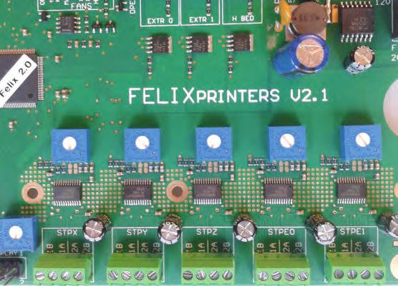
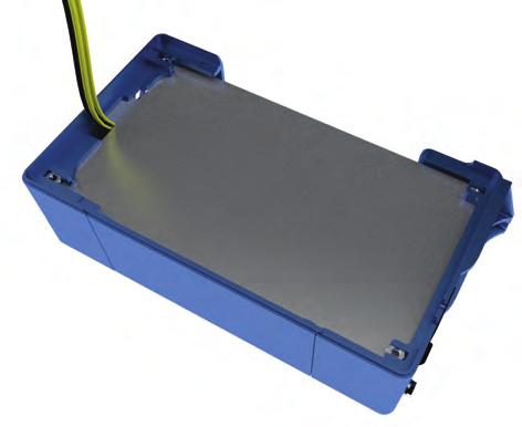
27 Module 7: electronics enclosure MInuTEs Step 84 / 92 tools: 84 1x Electronics enclosure pt2 1x Electronics enclosure pt1 2x Power suppley screw 2x Power supply screw

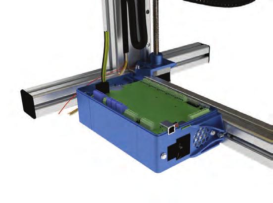
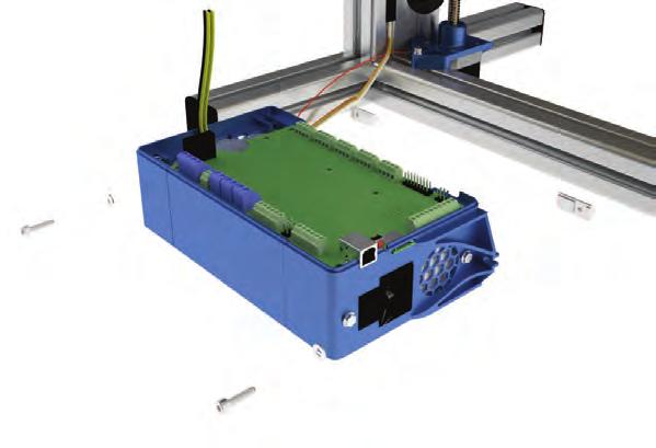
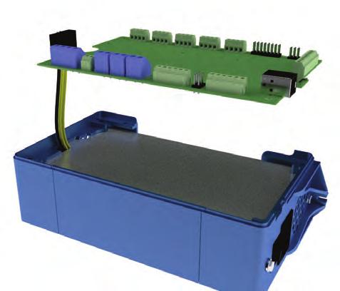
28 4x Thin square nut M4 87 1x Electronics enclosure cover plate x Bolt M4x12 2x small washer M4 2x T-slot M mm 29


29 Module 8: Wiring minutes Step 93 / 105 Tools: 10 Next steps are shown based on the double-extruder. For a single extruder you only need to connect the existing cables. 93 1x cable tie sticker 2x cable tie sticker 94 2x cable tie 2x cable tie 95 1x cable tie 2x cable tie 30


30 96 2x cable tie 97 25cm cable spiral 98 1x 15cm strip 1x 2cm strip 1x 6 cm strip 99 1x 28cm strip 4x cable ties The following steps are to connect the cables to the electronic-board. ATTENTION The electronics are sensitive to static electricity 31


31 strip the ends of the cable mm 5mm 103 1x 15 cm Cable spiral Wire diagram Single-head: page 33 Wire diagram dual-head: page 34 32

32 100 Wiring diagram for the single extruder.

33 100 a Wiring diagram for the dual extruder.


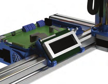
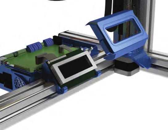
34 x small screw 2,2 x x Plastic Display-cover 35


35 109 1x Plastic knob 110 2x small screw 2,2 x Connecting the display cables 112 Attach the cover 1x Electronics enclosure cover 4x Bolt M4x12 Align the square nuts from step 88 properly before mounting the cover with the m4x12 bolts. 36


36 113 Kapton sheet note: It is best to place the kapton sticker when the bed is around C. This can be done with the computer interface or the display unit. Read the user manual to learn how to do this. clean the print-bed surface with detergent, and try to minimize dust particles onto the surface to prevent bubbles. Peel off a corner Peel off a corner of the large kapton sticker and fold the corner back. Place the kapton sticker onto the aluminum printbed. Make sure the corners align. Slowly peel the backing of the sticker an rub the sticker diagonally onto the printbed surface. To prevent/minimize bubbles, you can use a credit card. Congratulations you are finished with the assembly of the printer. Please continue with the user manual. 37

37 BOM ( Bill of Materials) Prod. Nr. Description Image Bolts & Nuts set FELIX 3.0b Set screw D-916 M3 x Set screw D M3 x 6-N -45H Set screw D M4 x Hexagon socket head cap screw M3 x Bolt D M3 x N - CSK Bolt D M3 x N - CSK Hexagon socket head cap screw DIN M3 x Hexagon socket head cap screw DIN M3 x Hexagon socket head cap screw DIN M3 x Hexagon socket head cap screw DIN M3 x Hexagon socket head cap screw DIN 912 M4 x Hexagon socket head cap screw DIN 912 M4 x Hexagon socket head cap screw DIN 912 M4 x 20 15


38 Hexagon socket head cap screw DIN 912 M4 x Hexagon socket head cap screw DIN 912 M4 x Hexagon socket head cap screw DIN 912 M5 x WasherD- 125A M WasherD- 125A M WasherD- 125A M Corrosserie ring - M4 - large washer Prevailing torque type hexagon nut DIN M Prevailing torque type hexagon nut DIN M Hexagon Thin Nut D-439B M Thin square nut DIN 562 Steel M Powersupply screw UNC 6/32 x ¼ Pozi steel Penhead screw D-7981-f 2,2 x 8 Phillips 8

39 t_slot nut 5 ST M t_slot nut 8 ST M Spring (heated_bed and extruder) Set plastic parts Felix 3.0 (molded) X_stage_F3_0_motor_bracket_v X_stage_F3_0_belt_mount_v Y_stage_F3_0_Bracket pt1_v Y_stage_F3_0_Bracket pt2_v Y_stage_F3_0_tensioning_bracket_v z_axis_f3_0_lift_part_v z_axis_f3_0_motor_bracket_v z_axis_f3_0_limitswitch_vane_v1 1

40 Extru_F3_0_base_v Extru_F3_0_L_shape_bracket_v Extru_F3_0_arm_pt1_v Extru_F3_0_arm_pt2_v Extru_F3_0_airduct_v Electronics_enclosure_F3_0_cap_pt Electronics_enclosure_F3_0_cap_pt Electronics_enclosure_F3_0_cover_v Electronics_enclosure_F3_0_cover_plate_v Electronics 1, F3_0b Thermistor incl 2m Electronics board - Felixprinters Fan 40x40x10 with 1.5m wires, Sunon Opto sensor_v2 3


41 cable ties, set of cable spiral 1.25m Cable ties for mounting cables on z bracket cable tie stickers on extruder motor Electronics 2 (motors) motor nema Mechanics, F3_0b pulley_motor_htd Toothbelt HTD 3M 1.2m Bearing 624 5x12x6 6


42 Frame (A) x40x400 profile incl 2xM x40x400 profile, incl 1xM8, 1xD x40x400 profile, incl 3xD x40x440 incl work Frame (B) x40 protective caps x40 protective caps frame connector set handle Protective cap, handle 1
43 hex sockethead bolt M8x16 buttonhead t-slot nut - 8 ST M t-slot nut - 8 ST M dampning feet Axlesembled Hot-end, containing: Hot_End_baxlee_1_75mm_F2_0_V Hot_End_peek_isolation_1_75 F2_0_v Hot_End_Heated_barrel_1_75_F2_0_v3 1

44 Hot_End_tip_1_75_F2_0_v Heater Cartidge incl 2m wires Thermistor incl 2m 1 Parts packed separately in DIY kit Powersupply - 1U- Enhanced electronics, with switch table_6mm_f3_0_v Trapezium spindle TR10x2mm 330mm Trapezium hexagon nut TR10x Kapton - Foil Heater Hiwin lineair ball bearing set MGN12H1R0300Z1HM Hiwin lineair ball bearing set HGW15CC1R300Z strip for putting away cable pieces of 40 cm 3


45 Miscellaneous USB cable 1.8m tweezers Kapton Sheet Piece of filament to start 5m Piece of teflon tube 40cm Bearing 25x32x7, used for filament holder Filament dust cleaner 2 Optional parts depending on region Power Cable EU Power Cable USA Power Cable AU Power Cable UK 1
46 Upgrade kit single to dual head F3.0b piece of tefon tube 50cm strip for putting away cable pieces of 40 cm Hot-end v4, axlesembled Fan 40x40x10 with 1.5m wires, Sunon Stepper motor nema 17, short motor, 1.5m wires, flat shaft small bearing Filament dust cleaner extruder_insert_part_v Prevailing torque type hexagon nut DIN M Hexagon socket head cap screw M3 x Dual_Extruder_Clamp Dual_Extruder_Mover 1
MP Maker Pro Mk.1. Quick Start Guide
 MP Maker Pro Mk.1 P/N 33013 Quick Start Guide ONLINE SUPPORT Monoprice is pleased to provide free online support. For order related issues, contact the Customer Service department through the Live Chat
3. Electronics and MMU2 unit assembly
 Written By: Jakub Dolezal 2018 manual.prusa3d.com/ Page 1 of 34 Step 1 Tools necessary for this chapter Please prepare tools for this chapter: 2.5mm Allen key for M3 screws 2mm Allen key for nut alignment
easydelta BUILD MANUAL easydelta 3D printer design & documentation by Achatz Industries Haefland 8A 6441 PA Brunssum The Netherlands
 easydelta BUILD MANUAL easydelta 3D printer design & documentation by Achatz Industries Haefland 8A 6441 PA Brunssum The Netherlands BUILD MANUAL Welcome to the 1. Edition Build Manual for your easydelta
8. Electronics. 8. Electronics. Electronics guide. Written By: Dozuki System manual.prusa3d.com Page 1 of 12
 8. Electronics Electronics guide Written By: Dozuki System 2017 manual.prusa3d.com Page 1 of 12 Step 1 3D printed parts Back Rambo-cover Right Rambo-cover Left Rambo-cover Step 2 Assembling the Electronics
Dual extruder upgrade manual addendum to assembly manual
 Dual extruder upgrade manual addendum to assembly manual This manual is intended for users that have bought the kit WITH a new printer. For user that already have their printer assembled and working, please
Bionic Elephant Trunk. Assembly Instructions
 Bionic Elephant Trunk Assembly Instructions Equipment and Supplies Required items from the Bionics Kit and/or Materials Pack: 1. Tail fin (small) assembled 2 see Start Here for tail fin assembly instructions
DLMP Installation Instructions
 DLMP Installation Instructions Tools Needed Posidrive No.3 Screwdriver Large Flat Head Screwdriver 2x 10mm Spanner 1x 13mm Spanner Ø8mm Drill Ø6mm Drill Kit Contents [ ] 1x Tube 2.5M long 17420 [ ] 2 x
Single sensor setup with NIVEL210
 Single sensor setup with NIVEL210 Essential Items: 576 198 NIVEL210 RS232 748 335 Cable, Lemo 0 power supply cable Lemo 1 802 902 Cable, Lemo 0 722 409 Power supply plus power cords 802 902 576 198 748
For printer model: TG3 Series
 RFID User Guide Parts List For printer model: TG3 Series PN: 9001227(A) Read this User Guide before and during usage of the above product. Keep this document handy for future reference. www.satoamerica.com
DLMP-45/45R Installation Instructions
 DLMP-45/45R Installation Instructions Tools Needed Posidrive No.3 Screwdriver Large Flat Head Screwdriver 2x 10mm Spanner 1x 13mm Spanner Ø8mm Drill Ø6mm Drill Kit Contents [ ] 1x Tube 2.5M long 17420
M-8460Se Printer Standard Unit
 M-8460Se Printer Standard Unit Parts List Page 1-1 P/N 9001090 Table of Contents M-8460Se Spare Parts List Page Frame Assembly...3 Print Head Assembly...8 Ribbon Assembly... 11 Platen Frame Assembly...14
Optical Distribution Box 300 Installation Guide. Version : R0.0
 Optical Distribution Box 300 Installation Guide Document No. : OD16-546-L-01 Version : R0.0 Date: 21-Mar-2018 IMPORTANT INSTRUCTIONS When using fiber optic equipment, basic precautions should always be
Setup Guide. Read me BefoRe unpacking!
 Setup Guide Read me BefoRe unpacking! Package Contents In The Replicator package The Replicator SD card (in The Replicator SD card slot) In the Accessory Box found within The Replicator frame Single or
SJOF-BS604B. Fiber Optic Splice Closure User Manual Rev.1
 Fiber Optic Splice Closure 1. Introduction 1.1 General SAMJIN s SJOF-BS604B protects fiber optic splicing point in various installation conditions such as aerial, manholes, ducts, wall and direct buried
M8400RV Base Cover Assembly Item # Part Number Part Description Qty
 Base Cover Assembly Item # Part Number Part Description Qty 1 PH1741200 Base frame 1 2 PT6680100 Rubber foot 4 3 PA3741000 Frame bracket 1 4 MD4301022 Pan head screw 3 5 PA3742500 Frame bracket 1 6 MD4301022
M-8400RVe Printer. Parts List. Page 1-1. P/N Rev.B
 M-8400RVe Printer Parts List Page 1-1 P/N 9001085 Rev.B Table of Contents M-8400RVe Parts List Page Frame Assembly...3 Head Assembly... 8 Ribbon Assembly... 11 Feed Roller Assembly... 16 Base Cover Assembly...
1.8 METER SERIES 1183 Az/El MOUNT ANTENNA SYSTEM
 REVISION G January 11, 2002 ASSEMBLY MANUAL 1.8 METER SERIES 1183 Az/El MOUNT ANTENNA SYSTEM PRODELIN CORPORATION 1500 Prodelin Drive Newton NC 28658 1.8 METER SERIES 1183 Az/El MOUNT ANTENNA SYSTEM G
Cable ISOBUS Active Termination
 ISOBUS Retrofit Kit Ag Leader Technology Note: Indented items indicate parts included in an assembly listed above Part Name/Description Part Number Quantity ISOBUS Retrofit Kit 4100843 1 Hex Head Bolt
M SERIES DISPENSER M SERIES DISPENSER
 M SERIES DISPENSER PART NUMBER 5006621 M SERIES DISPENSER M SERIES DISPENSER... M - 1 M15 TOP EXPLODED VIEW... M - 2 M15 TOP PARTS LIST... M - 3 M15 BASE EXPLODED VIEW... M - 4 M15 BASE PARTS LIST... M
Adjustable Mast Bracket Installation Guide
 Fig. 2: Wall Mounting Pattern Fig. 1: Adjustable Mast Bracket BOM ITEM QTY DESCRIPTION 1 1 MAST BRACKET, ADJUSTABLE, METRIC, M65-1.5 2 4 WASHER, SPLT LK, M8, DIN 127B, STEEL, ROHS HOT DIP GALV 3 4 SCREW,
INSTALLATION INSTRUCTIONS
 INSTALLATION INSTRUCTIONS PARTS REQUIRED Parts in the box Single monitor Dual monitor M2 M8 M/Flex + (package contents will depend on configuration ordered) Tools required for installation 6.0 mm Hex Key
Materials: Programming Objectives:
 Lessons Lesson 1: Basic Chassis Overview TETRIX Getting Started Guide In this lesson, users will learn how to use the elements of the TETRIX system that will be involved in building the basic chassis of
2100/2200/4100/6200 & MPB Series Bottom Mount Drive Pack. for Standard Load Parallel Shaft 60 Hz Gearmotors
 00/00/400/600 & MPB Series Bottom Mount Drive Pack. for Standard Load Parallel Shaft 60 Hz Gearmotors Installation, Maintenance & Parts Manual DORNER MFG. CORP. INSIDE THE USA OUTSIDE THE USA P.O. Box
ASSEMBLY, INSTALLATION, AND REMOVAL OF CONTACTS AND MODULES
 ASSEMBLY, INSTALLATION, AND REMOVAL OF CONTACTS AND MODULES FOR 75 OHM AND 75 OHM HD COAXIAL CONTACTS AND MODULES Table of Contents SECTION 1 RECEIVER CONTACT ASSEMBLY INSTRUCTIONS SECTION 2 ITA CONTACT
TYPE ASR 650 / 850 FLAT LIST 1/3
 TYPE ASR 650 / 850 FLAT LIST 1/3 TYPE ASR 650 / 850 FLAT LIST 1/3 NR. ARTICLECODE DESCRIPTION REMARKS 1 110006000.2 Fixation (grey) for antenna ASR 650 FLAT 1 110006004 Fixation (grey) for antenna ASR
INSTALLATION INSTRUCTIONS
 LIGHTGUARD 350-20-WTC SEALED FIBER OPTIC CLOSURE VIEW ONLINE TABLE OF CONTENTS: GENERAL...2 SPECIFICATIONS...2 PACKAGE CONTENTS...3 PACKAGE CONTENTS: ACCESSORIES...3 RECOMMENDED TOOLS...3 ADD-ON COMPONENTS...4
Step 1. 1x NXT Ultrasonic Sensor
 Start with the build completed in Lesson 3 of the TETRIX Getting Started Guide. Step 1 involves removing an element from the model. This element will be reattached later. Parts to be Removed Step 1 1x
Contents Section 9, Illustrated Parts
 Contents Section 9, Illustrated Parts Figures 9-1. Parts of RT7... 9-5 9-2. RT7 Drive Assembly... 9-9 9-3. RT7 Refrigeration System... 9-10 9-4. Parts of RT7 PLUS... 9-15 9-5. RT7 PLUS Drive Assembly...
ELLIPTICAL ANTENNA E0851B11
 ELLIPTICAL ANTENNA E0851B11 INSTALLATION GUIDE E0851B11 Installation Manual Step 1: Finding a suitable antenna site A suitable antenna site requires an unobstructed view and a stable antenna mounting surface.
Instruction Manual for the & Electronic Bingo Blower
 Instruction Manual for the 17212 & 17214 Electronic Bingo Blower The directions in this manual when referring to the 17212 are referring to software version 2.83 (you can find what version your blower
HQ Electromagnetic Channel Locks
 HQ Electromagnetic Channel Locks Table of Contents Overview... 2 Kit Contents... 2 Tools Required... 5 Installation... 5 Using the HQ Electromagnetic Channel Locks... 10 Troubleshooting... 11 Overview
M2 Antenna Systems, Inc. Model No: 23CM35
 M2 Antenna Systems, Inc. Model No: 23CM35 SPECIFICATIONS: Model... 23CM35 Frequency Range... 1250 To 1300 MHz *Gain... 20.94 dbi Front to back... 25 db Typical Beamwidth... E=17 H=18 Feed type... Folded
3M Fiber Optic Splice Closure 2178-XSB/XSB-FR & 2178-XLB/XLB-FR 3M Cable Addition Kit 2181-XB/XB-FR
 3M Fiber Optic Splice Closure 2178-XSB/XSB-FR & 2178-XLB/XLB-FR 3M Cable Addition Kit 2181-XB/XB-FR Instructions July 2010 78-8135-0094-5-K 3 1.0 General 1.1 3M Fiber Optic Splice Closure 2178-XSB The
Collator series 300/400, 310B Spare parts list
 Collator series 300/400, 30B Spare parts list AUGUST 997 Part # 9049 USER INFORMATION T0703 This Spare part list is devided into one Series 300/400 section, one 30 B section and one Paper feeder section.
2178-L/S Series Fiber Optic Splice Case with Gasket
 2178-L/S Series Fiber Optic Splice Case with Gasket Instructions for: 2178-S Splice Case 2178-LS Splice Case 2178-LL Splice Case 2181-LS Cable Addition Kit May 1997 34-7041-9949-5-A 1 Table of Contents
In-Ceiling Electric Motorized Front Projection Screen Evanesce Series. User s Guide
 In-Ceiling Electric Motorized Front Projection Screen Evanesce Series User s Guide Important Safety & Warning Precautions Make sure to read this user s guide and follow the procedures below. Caution: The
FOSC 450 C6 and D6 Closures
 FOSC 450 C6 and D6 Closures I N S T A L L A T I O N I N S T R U C T I O N Fiber Optic Splice Closure 1. General Product Information The FOSC 450 C6 and D6 fiber optic splice closures use compressed gel
Service Parts Diagrams. For Model: 10/20/09 Service Parts Diagrams for the Rear Projection SMART Board 3000i-DV Interactive Whiteboard 1
 Service Parts Diagrams For Model: 000i-DV with the serial NEC MT060 numbers Serial greater numbers than 000 000i-DV-09000 to 0999 0/0/09 Service Parts Diagrams for the Rear Projection SMART Board 000i-DV
Satellite Dish Installation Manual (Ver. 2) 1
 1") Satellite Dish Installation Manual Provided by DiscoverNet, Inc. Satellite Dish Installation Manual (Ver. 2) 1 Table of Contents Section 1: Introduction Page 3 Section 2: Recommended Tools and Materials
Satellite Dish Installation Manual Provided by DiscoverNet, Inc. Satellite Dish Installation Manual (Ver. 2) 1 Table of Contents Section 1: Introduction Page 3 Section 2: Recommended Tools and Materials
FOSC-600 C and D I N S T A L L A T I O N I N S T R U C T I O N
 FOSC-600 C and D I N S T A L L A T I O N I N S T R U C T I O N In-line and butt version Cold applied re-usable fiber optic closure Contents 1 Introduction 1.1 Product description 1.2 Capacity 2 General
USER MANUAL. GOLDMUND LOGOS 1N-2N SPEAKER SYSTEM Active Speaker
 USER MANUAL GOLDMUND LOGOS 1N-2N SPEAKER SYSTEM Active Speaker Thank you for purchasing the Goldmund LOGOS 1N-2N SPEAKER SYSTEM The Goldmund Logos line fully incorporates the technological expertise developed
Installation Manual IPT Installation of skillet systems with 125 A track current. MV a-E.
 www.wampfler.com Page 1 of 27 Index Page 1 Basics...4 2 Basic understanding of an IPT -system...5 3 General rules regarding metal parts in close proximity...6 3.1 Envelope free of ferromagnetic material...6
2100, 2200, 4100, 6200, MPB Series Side Mount Drive Package for Light Load 60 Hz Gearmotors
 00, 00, 400, 600, MPB Series Side Mount Drive Package for Light Load 60 Hz Gearmotors Installation, Maintenance & Parts Manual DORNER MFG. CORP. INSIDE THE USA OUTSIDE THE USA P.O. Box 0 975 Cottonwood
Medium Box for Cable Termination
 FIST-MB2-T I N S T A L L A T I O N I N S T R U C T I O N Medium Box for Cable Termination Contents 1 Introduction 1.1 Product description. 2 General 2.1 Tools 2.2 Kit contents 3 Installation and pre assembling
Fiber Optic Splice Closure GPJ Instruction Manual
 Fiber Optic Splice Closure GPJ09-9401 Instruction Manual 1. Brief Introduction GPJ09-9401 type of Fiber Optic Splice Closure is a member in dome series, the main function is to provice direct pass, branch
FIST-MB2-S. FIST Medium Box for Cable Splicing Only. 4 Cable installation. 1 Introduction. Contents. 2 General. 5. Fiber routing to individual trays
 FIST-MB2-S I N S T A L L A T I O N I N S T R U C T I O N FIST Medium Box for Cable Splicing Only Contents 1 Introduction 1.1 Product description 2 General 2.1 Tools 2.2 Kit contents 3 Installation and
A449-6S 70 CENTIMETER FM YAGI ANTENNA MHz
 ASSEMBLY AND INSTALLATION A449-6S 70 CENTIMETER FM YAGI ANTENNA 440-450 MHz COMMUNICATIONS ANTENNAS 951425 (7/93) WARNING THIS ANTENNA IS AN ELECTRICAL CONDUCTOR. CONTACT WITH POWER LINES CAN RESULT IN
Installation instructions, accessories. Subwoofer. Volvo Car Corporation Gothenburg, Sweden. Page 1 / 29
 Installation instructions, accessories Instruction No 30752136 Version 1.1 Part. No. 30752135 Subwoofer Volvo Car Corporation Subwoofer- 30752136 - V1.1 Page 1 / 29 Equipment A0000162 A0000161 A0801178
The Haply Development Kit
 The Haply Development Kit Introduction The Haply development kit is a robust and adaptable open-source hardware development platform for haptic applications. Designed to be accessible to novices and experts
03-Durchfuehren_RZ_0708_EN.qxd:03-Durchfuehren GB.qxd :06 Uhr Seite 200 Feed-through
 Feed-through Feed-through FEED-THROUGH Series Size Page Rotary Feed-through for Robots DDF 202 DDF 031 206 DDF 040 208 DDF 040-1 210 DDF 050 212 DDF 050-1 214 DDF 063 216 DDF 080 218 DDF 080-1 220 DDF
Field Service Procedure Replacement PCU Kit, Coastal
 1. Brief Summary: Troubleshooting document for diagnosing a fault with and replacing the PCU assembly on the coastal series antennas. 2. Checklist: Initialization Rate Sensor Outputs Run the Built In Test
Operating Manual. Automated Gear. Apollo Design Technology, Inc Fourier Drive Fort Wayne, IN USA
 Operating Manual Automated Gear Apollo Design Technology, Inc. 4130 Fourier Drive Fort Wayne, IN 46818 USA PH: +01(260)497-9191 FX: +01(260)497-9192 www.apollodesign.net 11-25-09 5-6 POWERING UP THE RIGHT
Challenges. TETRIX Getting Started Guide STEM Challenge Building Guide. Step 1. Parts Needed. Tips
 Note: The Arm and Gripper Extension has been recommended as an initial build to complete the STEM Challenge. The STEM Challenge Sample Program and Programming Guide have been created to work effectively
Instruction manual. Midi Fiber Dome. Instruction manual
 Midi Fiber Dome Instruction manual Product contents: - 1x Midi Fiber Dome - 1x Window Cut port seal - 1x sealing rubber (long) - 4x sealing rubber (short) - 4x stainless steel screw 4 x 25 T20-6x dummies
3M Better Buried Compound Compression Closure System
 3M Better Buried Compound Compression Closure System Instructions March 2016 78-0015-2948-2-A Contents: 1.0 General...3 2.0 Kit Contents...3 3.0 Closure Selection Guide...4 4.0 LHS End Cap Installation...5
Formulate Designer Series 20 Backwall - Kit 07
 Formulate Designer Series 20 Backwall - Kit 07 FMLT-DS-20-07 Formulate TM Designer Series 20ft displays have unique stylistic features and shapes, are portable and easy to assemble. The aluminum tube frame
Field Service Procedure Replacement EL Motor Kit, ST24
 1. Brief Summary: Troubleshooting document for diagnosing a fault with and replacing the elevation motor and encoder on the ST24 antenna. 2. Checklist: Verify Initialization Run the Built In Test 3. Theory
Manual placement system MPL3100. for BGA, CSP and Fine-Pitch components
 Manual placement system MPL3100 for BGA, CSP and Fine-Pitch components Part No: MPL3100BA1.0e Issue Date: 02/2001 You have opted for an ESSEMTEC MPL3100 pick and place system. We thank you for this decision
3M Distribution Box (DDB)
") 3M Distribution Box (DDB) Merged Copper and Fiber Pole/Post Mount Enclosure Installation Instructions November 2015 78-0015-2736-1-A 2 November 2015 78-0015-2736-1-A Contents 1.0 General 2.0 Enclosure
3M Distribution Box (DDB) Merged Copper and Fiber Pole/Post Mount Enclosure Installation Instructions November 2015 78-0015-2736-1-A 2 November 2015 78-0015-2736-1-A Contents 1.0 General 2.0 Enclosure
INSTALLATION INSTRUCTIONS
 INSTALLATION INSTRUCTIONS BEFORE INSTALLING OR ADJUSTING THIS PRODUCT, PLEASE READ THESE INSTRUCTIONS CAREFULLY. PLEASE KEEP THIS GUIDE FOR FUTURE REFERENCE FIBER OPTIC SWING-OUT PATCH PANEL INSTRUCTION
Assembling and Mounting the Presentation Display, Speakers, Speaker Screens, and Table Door
 CHAPTER 8 Assembling and Mounting the Presentation Display, Speakers, Speaker Screens, and Table Door July 13, 2012, This document provides you with the procedures you perform to assemble and mount the
Instruction Manual for Electronic Blowers and Flashboards
 Instruction Manual for Electronic Blowers and Flashboards These instructions cover both the table model 17212 table top Electronic Bingo Blower (Fig 1) and the 17213 floor model Electronic Bingo Blower
PARTS LIST FOR CM-1250-A/C 1.5 HP
 8650 Enterprise Drive, Peosta IA 52068 563-556-7484 / Fax 563-556-1235 PARTS LIST FOR CM-1250-A/C Motor Specs: Pump Oil: Pump Oil Capacity: Nozzle Size: 1.5 HP / 1 Phase / 115 Volts Mi-T-M #AW-4085-0016
We are your competent partner for cable routing
 A Phoenix Mecano Company We are your competent partner for cable routing...ensuring your production processes don't get left hanging. BLOCAN Cable Channel System BLOCAN Cable Channel System Channel functionality
A CENTIMETER FM YAGI ANTENNA MHz
 ASSEMBLY AND INSTALLATION A449-70 CENTIMETER FM YAGI ANTENNA 440-450 MHz COMMUNICATIONS ANTENNAS 951424 (10/91) WARNING THIS ANTENNA IS AN ELECTRICAL CONDUCTOR. CONTACT WITH POWER LINES CAN RESULT IN DEATH
3M Locator Plate N
 M Locator Plate 44-107N Instructions for the assembly of.100 x.100 preassembled socket connectors 1.0 General The M Locator Plate 44-107N is designed to aid in the assembly of the preassembled socket connector
3 Closure preparation 3.1 Work-stand 3.2. Opening FIST-GCOG2-Dx Preparing drop cable with micro-tubes
 FIST-GCOG2-Dx24 I N S T A L L A T I O N I N S T R U C T I O N FTTH closure for micro-tubes and micro-cables Content 1 Introduction 2 Kit content 3 Closure preparation 3.1 Work-stand 3.2. Opening FIST-GCOG2-Dx24
DREAMOC DIAMOND 4K - ASSEMBLY GUIDE VERSION ORIGINAL ASSEMBLY GUIDE
 DREAMOC DIAMOND 4K - ASSEMBLY GUIDE VERSION 1.2 - ORIGINAL ASSEMBLY GUIDE It is important to read this assembly guide before using the Dreamoc Diamond, and to follow advices and instructions on safety,
Snail Fence InteleCell Deployment Guide
 Snail Fence InteleCell Deployment Guide Preparation 1. Prepare deployment trip by making sure you have the following materials and tools when you fly up to the site: InteleCell NEMA Enclsoure (grey plastic
GENUINE PARTS ! CAUTION
 GENUINE PARTS SATELLITE RADIO INSTALLATION INSTRUCTIONS 1. DESCRIPTION: SATELLITE RADIO SYSTEM 2. PART NUMBERS: XM tuner kit 999U9-NV003 Sirius tuner kit 999U9-NV004 XM antenna kit 999U9-VQ006 Sirius antenna
Step 1. 2x Kep Nut 1x Left Motor Assembly
 Start with the build completed in Lesson 3 of the TETRIX Getting Started Guide. Steps 1 to 3 involve removing elements from the model. These elements will be reattached later. Parts to be Removed Step
3M Fiber Optic Splice Closure 2178-L/S Series with Gasket
 3M Fiber Optic Splice Closure 2178-L/S Series with Gasket Instructions for: 3M Fiber Optic Splice Closures 2178-L/S Series 3M Flame Retardant Fiber Optic Splice Closures 2178-L/S/FR 3M Cable Addition Kit
Electric Motorized Projection Screen PowerMax Tension Series
 Electric Motorized Projection Screen PowerMax Tension Series User s Guide Important Safety & Warning Precautions Make sure to read this user s guide and follow the procedures below. Caution: The screen
RKSlimlift / EM. Two-stage lifting column
 RKSlimlift / EM Two-stage lifting column Two-stage lifting column - RKSlimlift / EM Rod-shaped design and extremely quiet operation RKSlimlift RKSlimlift EM 4 fixing threads 9Simple 9 connection Drive
CM MTC PARTS LIST
 8650 Enterprise Drive, Peosta IA 52068-0050 319-556-7484 / Fax 319-556-1235 CM-2400-0MTC PARTS LIST ENGINE OIL GRADE: ENGINE OIL CAPACITY: PUMP OIL: PUMP OIL CAPACITY: NOZZLE SIZE: 30W 21 oz. MI-T-M #AW-4085-0016
Endurance Robotics PT-3
 Endurance Robotics PT-3 The Endurance Robotics Pan and Tilt PT-3 base is a rugged pan and tilt system based around standard sized hobby servos. Featuring all around rigid 1/4" ABS laser cut construction,
2000i. Projector Replacement Guide. for Projector Replacement Kits. NEC MT1060R ( ) and NEC MT860R ( ) Interactive Whiteboard
 and NEC MT860R ( ) Interactive Whiteboard") 2000i Interactive Whiteboard Projector Replacement Guide for Projector Replacement Kits NEC MT1060R (03-00043) and NEC MT860R (03-00041) 99-00496-00 Rev A0 FCC Warning This equipment has been tested and
2000i Interactive Whiteboard Projector Replacement Guide for Projector Replacement Kits NEC MT1060R (03-00043) and NEC MT860R (03-00041) 99-00496-00 Rev A0 FCC Warning This equipment has been tested and
Instruction manual. KUZMA 4POINT 14 inch TONEARM Serial Number:
 Instruction manual KUZMA 4POINT 14 inch TONEARM Serial Number:.. 2016-09 1 KUZMA LTD INSTRUCTION MANUAL FOR 4POINT 14 tonearm The 4POINT 14 tonearm is a very precisely engineered piece of equipment, however,
Briggs&Stratton 44Q B1
 Accessories IPL, Briggs&Stratton 44Q777-1272-B1, 2010-03 Briggs&Stratton 44Q777-1272-B1 Spare parts Ersatzteile Pièces détachées Reserve onderdelen Repuestos Reservdelar 48 SHORT BLOCK 1329 REPLACMENT
3 SLiC Aerial Closure with Rubber End Seal
 3 Aerial Closure with Rubber End Seal Instructions 1.0 General 1.1 This instruction bulletin describes the assembly of the 3M Aerial Closure with external bonding hanger brackets. These closures are suitable
NC-1000 INSTALLATION MANUAL NC-1000 FIBRE OPTIC CROSS-CONNECTION SYSTEM
 NC-1000 INSTALLATION MANUAL NC-1000 FIBRE OPTIC CROSS-CONNECTION SYSTEM Content 1. General 5 2. The products of NC-1000 system 6 3. Mounting of the frame 8 4. Earthing of the frame 8 NC-1000 FIBRE OPTIC
3M Fiber Optic Splice Closure 2178-XL & 2178-XL/FR
 3M Fiber Optic Splice Closure 2178-XL & 2178-XL/FR 3M Cable Addition Kit 2181-XL and 2181-XL/FR Instructions September 2017 78-8130-5055-2-M 2 September 2017 78-8130-5055-2-M 1.0 Kit Contents 2.0 General...
3M Fiber Optic Wall Mount Enclosure 8430 Series
 3M Fiber Optic Wall Mount Enclosure 8430 Series Installation Instructions January 2014 3 78-0013-9429-1-A Table of Contents 1.0 Description...3 2.0 Parts...4 3.0 Assembly...4 4.0 Mounting the Enclosure...6
3M Fiber Optic Splice Closure 2178-XL & 2178-XL/FR 3M Cable Addition Kit 2181-XL and 2181-XL/FR
 3M Fiber Optic Splice Closure 2178-XL & 2178-XL/FR 3M Cable Addition Kit 2181-XL and 2181-XL/FR Instructions July 2010 3 1.0 Contents 1.0 General...3 2.0 Kit Contents...3 3.0 Cable Preparation...4 4.0
SCREEN WINCH SYSTEM INSTALLATION MANUAL FOR SCREENS UP TO 300 cm. of width
 SCREEN WINCH SYSTEM INSTALLATION MANUAL FOR SCREENS UP TO 300 cm. of width Before installing the screen winch system, please read the following instructions carefully: The screen winch system must be used
SCREEN WINCH SYSTEM INSTALLATION MANUAL FOR SCREENS UP TO 300 cm. of width
 SCREEN WINCH SYSTEM INSTALLATION MANUAL FOR SCREENS UP TO 300 cm. of width Before installing the screen winch system, please read the following instructions carefully: The screen winch system must be used
VITALink Taped Splice Straight Through Crimp
 A Marmon Wire & Cable Berkshire Hathaway Company VITALink Taped Splice Straight Through Crimp 2 Hour Fire-Rated Splice VITALink MC Cables, UL FHIT 120 Installation Instructions Description The VITALink
MAGNETIC CARD READER DESIGN KIT TECHNICAL SPECIFICATION
 MAGNETIC CARD READER DESIGN KIT TECHNICAL SPECIFICATION Part Number: D99821002 Rev 212 MAY 2017 REGISTERED TO ISO 9001:2008 1710 Apollo Court Seal Beach, CA 90740 Phone: (562) 546-6400 FAX: (562) 546-6301
Section 2 Normal Procedures
 1 Section 2 Normal Procedures The Pro Flight Trainer Evolution BL is a HID USB Device that Plug & Play to any compatible Operating System. It will be recognized as a USB Input Device with 5 axis, 6 buttons,
FIST-GCOG2-Dx6. Follow all local safety regulations related to optical fiber plant elements.
 FIST-GCOG2 I N S T A L L A T I O N I N S T R U C T I O N TC-986-IP Rev A, Mar 2017 www.commscope.com FIST-GCOG2-Dx6 Content 1 Introduction 2 General 2.1 Abbreviations 2.2 Kit contents 2.3 Tools 2.4 Accessories
2178 Fiber Optic Splice Case and 2181 Cable Addition Kit
 2178 Fiber Optic Splice Case and 2181 Cable Addition Kit Instructions January 1994 Issue 1, 34-7029-6387-6 1 2 Contents: 1.0 General... 4 2.0 Specifications... 4 3.0 Kit Contents... 5 SECTION 1: 2178 Splice
HD Flex Patch Panel. ASSEMBLY VIEW (FLEX1UPN** shown) FS128B. CONTENTS: (#) indicates FLEX4UPN** quantity
 FS128B. CONTENTS: (#) indicates FLEX4UPN** quantity") HD Flex Patch Panel Part Numbers: FLEX1UPN**, FLEX2UPN**, FLEX4UPN** Panduit Corp. 2018 INSTALLATION INSTRUCTIONS Note: HD Flex Patch Panels are compatible with HD Flex Fiber System Components. HD Flex
HD Flex Patch Panel Part Numbers: FLEX1UPN**, FLEX2UPN**, FLEX4UPN** Panduit Corp. 2018 INSTALLATION INSTRUCTIONS Note: HD Flex Patch Panels are compatible with HD Flex Fiber System Components. HD Flex
Assembly instructions
 Assembly instructions Model: MXR0024/KIT TV Aerial - 18 Element Kit Contact: Helpline: +44 (0)1553 811000 Email: support@maxview.co.uk Web: www.maxview.co.uk Maxview reserve the right to change specifications
Up to 85% higher Service Life due to efficient sealing method.
 Robot Accessories Feeding through Up to 85% higher Service Life due to efficient sealing method. 346 Robot Accessories Feeding through Feeding through DDF 2 Rotary Feed-through Series Size Page DDF 2 348
PC-250. SMD Taped Parts Counter Operator s Manual. ISO 9001:2008 Certified. V-TEK, Incorporated 751 Summit Avenue Mankato, MN USA
 PC-250 SMD Taped Parts Counter Operator s Manual ISO 9001:2008 Certified V-TEK, Incorporated 751 Summit Avenue Mankato, MN 56001 USA (P) 507-387-2039 (F) 507-387-2257 www.vtekusa.com Dear Customer: All
PowerBook G4 Aluminum 12" GHz LCD panel upgrade
 PowerBook G4 Aluminum 12" 1-1.5 GHz LCD panel upgrade Upgrade a 1400x1050 LCD panel. Written By: martin ifixit CC BY-NC-SA www.ifixit.com Page 1 of 18 INTRODUCTION The original LCD 1024x768 resolution
NWRG Nixie Watch. User Manual
 NWRG Nixie Watch User Manual 2 Copyright (C) 2012 Cathode Corner. All rights reserved. Printed in USA Watch made in USA 3 Table of Contents Introduction... 5 Warranty... 7 Operating Instructions... 9 Maintenance...
2.4 METER SERIES 1250 ANTENNA SYSTEM
 June 1,2009 Revision B Assembly Manual 2.4 METER SERIES 1250 ANTENNA SYSTEM General Dynamics SATCOM Technologies 1500 Prodelin Drive Newton NC 28658 2.4 Meter 2 Piece Az/El Installation Instructions B
Coyote popup display set up instructions
 Coyote popup display set up instructions Frame 1 2 3 Prepare frame for assembly by locating the purple hooks on top of the frame. Stretch frame to size, snapping magnetic locking arms together. Attach
How To: Replace the stock Antenna with a CB Antenna A CFans Members Mod Project by coyote
 How To: Replace the stock Antenna with a CB Antenna A CFans Members Mod Project by coyote Skill Level: Easy Disclaimer: Please use caution and seek professional assistance when necessary. ColoradoFans.com,