Challenges. TETRIX Getting Started Guide STEM Challenge Building Guide. Step 1. Parts Needed. Tips
|
|
|
- Phillip Riley
- 6 years ago
- Views:
Transcription


1 Note: The Arm and Gripper Extension has been recommended as an initial build to complete the STEM Challenge. The STEM Challenge Sample Program and Programming Guide have been created to work effectively with this build as a starting point for original building and programming solutions. Step 1 1x 96 mm Channel 1x 160 mm Channel 3x 1/2" SHCS 3x Kep Nut Tips Make sure all the internal screws are very secure, as they will be hard to re-tighten later. The 7/64", 5/64", and 3/32" hex keys will be needed to build this model. Use the 7/54" hex key for these screws throughout the model. Ensure that the teeth of the nut face the head of the screw. 246


2 TETRIX Getting Started Guide Step 2 1x Single-Servo Motor Bracket 1x Gear Hub Spacer 3x Kep Nut 3x 1.5" SHCS Tips Ensure that all screws are tightly secured at this point, as they will not be easily accessible later. Reminder: Ensure that the teeth of the nut face the head of the screw. 247


3 Step 3 40-Tooth Gear 1x Servo Horn 4x 1/2" SHCS 4x Kep Nut Tip Ensure that the teeth of the nuts are facing the gear. 248

4 TETRIX Getting Started Guide Step 4 1x 180 Servo Motor 4x 3/8" BHCS 4x Kep Nut 1x Servo Screw Tips Use the Phillips head on the 4-in-1 screwdriver to tighten the servo screw. This will keep the servo horn attached to the servo motor. Use the 5/64" hex key for the BHCS. 249


5 Step 5 1x 80-Tooth Gear 1x 100 mm Axle 2x Axle Hub 3x Bronze 2x 1/8" Axle Spacer 6x 1/2" SHCS Bushing Tip The 3/32" hex key is used on the axle hubs. 250


6 TETRIX Getting Started Guide Step 6 2x Flat Bracket 2x 1" Stand-Off Post 1x L Bracket 5x 5/16" SHCS 1x Kep Nut Tip Reminder: Ensure the teeth of the nut face the head of the screw. 251

7 Step 7 2x 1/2" SHCS 2x Kep Nut Tip Reminder: Ensure the teeth of the nuts face the head of the screw. 252


8 TETRIX Getting Started Guide Step 8 1x L Bracket 1x Servo Horn 3x 5/16" SHCS 3x Kep Nut Tip Reminder: Ensure the teeth of the nut face the head of the screw. 253

9 Step 9 2x 1" Stand-Off Post 2x 5/16" SHCS 254


10 TETRIX Getting Started Guide Step 10 1x Single-Servo Motor Bracket 1x Flat Bracket 1x 2" Stand-Off Post 4x 5/16" SHCS 3x Kep Nut Tip Reminder: Ensure the teeth of the nut face the head of the screw. 255


11 Step 11 1x 180 Servo Motor 4x 3/8" BHCS 4x Kep Nut 1x Servo Screw Tip Use a the Phillips head on the 4-in-1 screwdriver to tighten the servo screw. This will keep the servo horn attached to the servo motor. 256

12 TETRIX Getting Started Guide Step 12 2x 5/16" SHCS Tip To keep the arm oriented properly, tighten the screws bit by bit, alternating between them. 257


13 Step 13 1x TETRIX Hard Point Connector 1x 7-Module Beam 4x 3 Module Connector Peg with Friction 258


14 TETRIX Getting Started Guide Step 14 2x 3-Module Connector Peg with Friction 2x 5-Module Beam 1x NXT Touch Sensor 1x 20-Tooth Gear 1x 2-Module Axle 259

15 Step 15 2x 5/16" SHCS 2x Kep Nut Tip Turn the screws only until the hard point connector is securely attached to the TETRIX channel. 260

16 TETRIX Getting Started Guide Step 16 2x 1/2" SHCS 2x Kep Nut 261

17 Final View 262


18 TETRIX Getting Started Guide Servo Horn Adjustment Note: Whenever a servo motor is used to attach an extension, care must be taken to properly adjust the servo motor position so that the desired range of motion is achieved. The best way to adjust the servo position is to unscrew the servo horn and use it, and the extension that has been built onto it, like a wrench. Step 1 Starting Point: Attach the servo horn to adjust the servo position. Step 2 Rotate: Rotate the servo so that it has been positioned at the end of its range of motion. Step 3 Final Positioning: Reattach the servo horn with the extension piece in the appropriate position for that servo location. 263


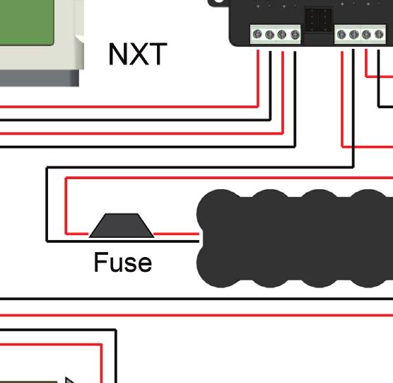

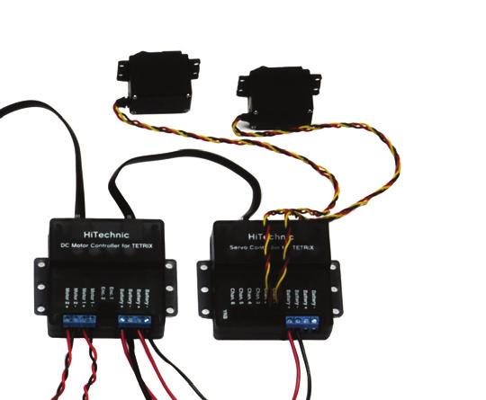
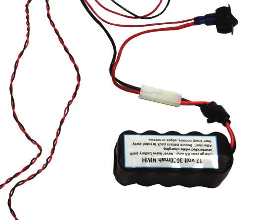

19 Wiring Diagram Tips Tighten the screws on the HiTechnic controller after the wires have been inserted. Complete all wiring before attaching the battery. 264
Step 1. 1x Single-Servo Motor Bracket. 1x L Bracket
 Extensions TETRIX Getting Started Guide Step 1 1x Single-Servo Motor Bracket 1x L Bracket 3x 5/16" SHCS 3x Kep Nut Tips The 7/64" and 5/64" hex keys will be used in this model. Ensure that the teeth of
Step 1. 1x NXT Ultrasonic Sensor
 Start with the build completed in Lesson 3 of the TETRIX Getting Started Guide. Step 1 involves removing an element from the model. This element will be reattached later. Parts to be Removed Step 1 1x
Step 1. 2x Kep Nut 1x Left Motor Assembly
 Start with the build completed in Lesson 3 of the TETRIX Getting Started Guide. Steps 1 to 3 involve removing elements from the model. These elements will be reattached later. Parts to be Removed Step
Materials: Programming Objectives:
 Lessons Lesson 1: Basic Chassis Overview TETRIX Getting Started Guide In this lesson, users will learn how to use the elements of the TETRIX system that will be involved in building the basic chassis of
Endurance Robotics PT-3
 Endurance Robotics PT-3 The Endurance Robotics Pan and Tilt PT-3 base is a rugged pan and tilt system based around standard sized hobby servos. Featuring all around rigid 1/4" ABS laser cut construction,
Bionic Elephant Trunk. Assembly Instructions
 Bionic Elephant Trunk Assembly Instructions Equipment and Supplies Required items from the Bionics Kit and/or Materials Pack: 1. Tail fin (small) assembled 2 see Start Here for tail fin assembly instructions
Backlight Replacement
 Installation Instructions Backlight Replacement Catalog Numbers 2711P-RL7C, 2711P-RL7C2, 2711P-RL10C, 2711P-RL10C2, 2711P-RL12C, 2711P-RL12C2, 2711P-RL15C Topic Page About This Publication 1 Important
ASSEMBLY, INSTALLATION, AND REMOVAL OF CONTACTS AND MODULES
 ASSEMBLY, INSTALLATION, AND REMOVAL OF CONTACTS AND MODULES FOR 75 OHM AND 75 OHM HD COAXIAL CONTACTS AND MODULES Table of Contents SECTION 1 RECEIVER CONTACT ASSEMBLY INSTRUCTIONS SECTION 2 ITA CONTACT
Hardware installation
 Hardware installation 5. Place and fix the OMT to the interface without tightening the screws. Figure 291: Place and fix the OMT to the interface Note: Take care to place the OMT with the engraved ARROW
TracVision M9 LNB Replacement Instructions
 TracVision M9 LNB Replacement Instructions These instructions explain how to replace an LNB with a new LNB of the same type in a TracVision M9. Installation Steps LNB Replacement Instructions 1. Remove
Replacing the PanelMate epro PS, PanelMate epro PS EE, and PanelMate epro PS OD 7685x-12 Series Backlight Assembly
 Replacing the PanelMate epro PS, PanelMate epro PS EE, and PanelMate epro PS OD 7685x-12 Series Backlight Assembly Introduction The Backlight Replacement Kit provides a replacement backlight for the PanelMate
2000 Series Weather Stations Analog Temperature / RH Sensor Upgrade Kit PRODUCT MANUAL KIT # 3613WDU
 2000 Series Weather Stations Analog Temperature / RH Sensor Upgrade Kit PRODUCT MANUAL KIT # 3613WDU 1 The 3613WDU Analog Temperature / RH Sensor Upgrade Kit is used to upgrade Watchdog 2000 Series Weather
General Wiring and Installation Guidelines. Typical Mounting Installations Electrical Connections General Guidelines Common Questions & Answers
 General Wiring and Installation Guidelines Typical Mounting Installations Electrical Connections General Guidelines Common Questions & Answers Congratulations on your purchase of a Dynapar brand encoder.
Satellite Dish Installation Manual (Ver. 2) 1
 1") Satellite Dish Installation Manual Provided by DiscoverNet, Inc. Satellite Dish Installation Manual (Ver. 2) 1 Table of Contents Section 1: Introduction Page 3 Section 2: Recommended Tools and Materials
Satellite Dish Installation Manual Provided by DiscoverNet, Inc. Satellite Dish Installation Manual (Ver. 2) 1 Table of Contents Section 1: Introduction Page 3 Section 2: Recommended Tools and Materials
MDT3 and MDT4 Service Parts
 This parts lists contains part numbers for the service parts available for the MDT and MDT4. They have been manufactured in both 60 Hz and 50 Hz models. The 60 Hz models are: MDTF-A or MDTFA-H MDT4F-A
FELIX3.1 assemblymanual
 FELIX3.1 assemblymanual Assemblymanualfor: FELIX3.1Single FELIX3.1Dual copyrightinformation Thisdocumentcontainsproprietaryinformationthatisprotectedbycopyright. nopartofthisdocumentmaybephotocopied,reproduced,ortranslatedtoanotherlanguagewithoutthepriorwritenconsentoffelixroboticsbv.
Service Parts Diagrams. For Model: 10/20/09 Service Parts Diagrams for the Rear Projection SMART Board 3000i-DV Interactive Whiteboard 1
 Service Parts Diagrams For Model: 000i-DV with the serial NEC MT060 numbers Serial greater numbers than 000 000i-DV-09000 to 0999 0/0/09 Service Parts Diagrams for the Rear Projection SMART Board 000i-DV
SRV02-Series. Rotary Pendulum. User Manual
 SRV02-Series Rotary Pendulum User Manual Table of Contents 1. Description...3 2. Purchase Options...3 2.1 Modular Options...4 3. System Nomenclature and Components...5 4. System Configuration and Assembly...6
Assembly instructions
 Assembly instructions Model: MXR0024/KIT TV Aerial - 18 Element Kit Contact: Helpline: +44 (0)1553 811000 Email: support@maxview.co.uk Web: www.maxview.co.uk Maxview reserve the right to change specifications
TV Lift System Model CL-65 Installation Instructions
 TV Lift System Model CL-65 Installation Instructions Contact: Support@Nexus21.com Toll Free: (866) 500-5438 Phone: (480) 951-6885 Fax: (480) 951-6879 Revised: 01/17/17 Below is a parts list describing
TracVision 95W LNB Installation
 TracVision 95W LNB Installation To enable a TracVision system to receive DIRECTV international programming from the linear satellite located at 95W, a 95W LNB must be installed in a secondary M7SK or M9
IMPORTANT! Special Instructions for the TracVision M3DX Conversion System ( )
") IMPORTANT! Special Instructions for the TracVision M3DX Conversion System (01-0279-05) You have purchased a special TracVision M3DX conversion system that can be configured for either circular or linear
IMPORTANT! Special Instructions for the TracVision M3DX Conversion System (01-0279-05) You have purchased a special TracVision M3DX conversion system that can be configured for either circular or linear
2100/2200/4100/6200 & MPB Series Bottom Mount Drive Pack. for Standard Load Parallel Shaft 60 Hz Gearmotors
 00/00/400/600 & MPB Series Bottom Mount Drive Pack. for Standard Load Parallel Shaft 60 Hz Gearmotors Installation, Maintenance & Parts Manual DORNER MFG. CORP. INSIDE THE USA OUTSIDE THE USA P.O. Box
03-Durchfuehren_RZ_0708_EN.qxd:03-Durchfuehren GB.qxd :06 Uhr Seite 200 Feed-through
 Feed-through Feed-through FEED-THROUGH Series Size Page Rotary Feed-through for Robots DDF 202 DDF 031 206 DDF 040 208 DDF 040-1 210 DDF 050 212 DDF 050-1 214 DDF 063 216 DDF 080 218 DDF 080-1 220 DDF
MultiConnect System. Installation Guide
 MultiConnect System Installation Guide Thank you for purchasing Inverto s innovative MultiConnect system and we are certain it will meet your expectations. Before installing the system, please read the
Caution. Hanging the Screen:
 Installation Instructions for Laminar and Laminar XL Projection Screens Caution 1. Read Instructions through completely before proceeding; keep them for future reference. Follow these instructions carefully.
M-8460Se Printer Standard Unit
 M-8460Se Printer Standard Unit Parts List Page 1-1 P/N 9001090 Table of Contents M-8460Se Spare Parts List Page Frame Assembly...3 Print Head Assembly...8 Ribbon Assembly... 11 Platen Frame Assembly...14
Flat. Compact. Cost-effective. FWS Flat Change System
 Flat. Compact. Cost-effective. FWS Flat Change System Manual tool changing system for small manipulators and grippers, with integrated air and electrical feed-through. Field of Application The changer
Product Manual MNX10015 / REV C MODEL SB142, SB242. Dual Output Series Switch Boxes
 Product Manual MNX10015 / REV C MODEL SB142, SB242 Dual Output Series Switch Boxes Contents Section I Overview Introduction.... 2 Description... 2 Section II Installation Mounting... 3 Electrical Connections...
Assembling and Mounting the Presentation Display, Speakers, Speaker Screens, and Table Door
 CHAPTER 8 Assembling and Mounting the Presentation Display, Speakers, Speaker Screens, and Table Door July 13, 2012, This document provides you with the procedures you perform to assemble and mount the
OWNER'S MANUAL SIGNAL COMMANDER
 OWNER'S MANUAL SIGNAL COMMANDER THIS MANUAL CONTAINS INSTRUCTIONS FOR: LPDA 200 - INSTALLATION - OPERATION - TROUBLESHOOTING - EXPLODED PARTS DRAWING - WARRANTY AntennaTek, Inc. 425 S. Bowen, #4 Longmont,
INSTALLATION INSTRUCTIONS
 INSTALLATION INSTRUCTIONS PARTS REQUIRED Parts in the box Single monitor Dual monitor M2 M8 M/Flex + (package contents will depend on configuration ordered) Tools required for installation 6.0 mm Hex Key
Cable ISOBUS Active Termination
 ISOBUS Retrofit Kit Ag Leader Technology Note: Indented items indicate parts included in an assembly listed above Part Name/Description Part Number Quantity ISOBUS Retrofit Kit 4100843 1 Hex Head Bolt
Arbor Scientific PO Box 2750 Ann Arbor, Michigan (800) Timer & Photogates 2.0 P Owners Manual
 Timer & Photogates 2.0 P Owners Manual") Arbor Scientific PO Box 2750 Ann Arbor, Michigan 48108 www.arborsci.com (800) 367-6695 Timer & Photogates 2.0 P4-1450 Owners Manual Stopwatch 0.01 second resolution to 999999.99 seconds Count FCC Compliance
Arbor Scientific PO Box 2750 Ann Arbor, Michigan 48108 www.arborsci.com (800) 367-6695 Timer & Photogates 2.0 P4-1450 Owners Manual Stopwatch 0.01 second resolution to 999999.99 seconds Count FCC Compliance
The NXT Big Thing #14
 The NXT Big Thing #14 The Sound Of... Robots? By Greg Intermaggio LDLDLDLDLDLLDDLLDLD! (Wookie for hello everyone!) In the last edition of The NXT Big Thing, we completed our gyro controlled robots. This
2.4 METER SERIES 1250 ANTENNA SYSTEM
 June 1,2009 Revision B Assembly Manual 2.4 METER SERIES 1250 ANTENNA SYSTEM General Dynamics SATCOM Technologies 1500 Prodelin Drive Newton NC 28658 2.4 Meter 2 Piece Az/El Installation Instructions B
TECHNICAL GUIDE. TOUGH GUN ThruArm G2 Series Robotic MIG Guns for FANUC Robots 100iC, 100iC-6L, 120iC, 120iC-10L INSTALLATION MAINTENANCE
 TECHNICAL GUIDE TOUGH GUN ThruArm G2 Series Robotic MIG Guns for FANUC Robots 100iC, 100iC-6L, 120iC, 120iC-10L INSTALLATION MAINTENANCE TECHNICAL DATA OPTIONS EXPLODED VIEW & PARTS LIST ORDERING INFORMATION
SCREEN WINCH SYSTEM INSTALLATION MANUAL FOR SCREENS FROM 300 cm. UP TO 450 cm. of width
 SCREEN WINCH SYSTEM INSTALLATION MANUAL FOR SCREENS FROM 300 cm. UP TO 450 cm. of width Before installing the screen winch system, please read the following instructions carefully: The screen winch system
ELLIPTICAL ANTENNA E0851B11
 ELLIPTICAL ANTENNA E0851B11 INSTALLATION GUIDE E0851B11 Installation Manual Step 1: Finding a suitable antenna site A suitable antenna site requires an unobstructed view and a stable antenna mounting surface.
2100, 2200, 4100, 6200, MPB Series Side Mount Drive Package for Light Load 60 Hz Gearmotors
 00, 00, 400, 600, MPB Series Side Mount Drive Package for Light Load 60 Hz Gearmotors Installation, Maintenance & Parts Manual DORNER MFG. CORP. INSIDE THE USA OUTSIDE THE USA P.O. Box 0 975 Cottonwood
imac Intel 27" EMC 2546 isight Camera and Microphone Cable Replacement
 imac Intel 27" EMC 2546 isight Camera and Microphone Cable Replacement Replace the isight/microphone cable in your Late 2012 27" imac. Written By: Andrew Optimus Goldberg ifixit CC BY-NC-SA www.ifixit.com
TYPE ASR 650 / 850 FLAT LIST 1/3
 TYPE ASR 650 / 850 FLAT LIST 1/3 TYPE ASR 650 / 850 FLAT LIST 1/3 NR. ARTICLECODE DESCRIPTION REMARKS 1 110006000.2 Fixation (grey) for antenna ASR 650 FLAT 1 110006004 Fixation (grey) for antenna ASR
INSTALLATION GUIDE DYNAMIC TRIM CONTROL SYSTEM SERIES S
 INSTALLATION GUIDE DYNAMIC TRIM CONTROL SYSTEM SERIES S Drill bits TOOLS Power drill Ø Ø Ø Ø Ø 2.5 mm (3/32 ) 3 mm (1/8 ) 3.5 mm (9/64 ) 4 mm (5/32 ) 5 mm (3/16 ) Sealant Hole saw Screw bits Ø 76 mm (3
1.8 METER SERIES 1183 Az/El MOUNT ANTENNA SYSTEM
 REVISION G January 11, 2002 ASSEMBLY MANUAL 1.8 METER SERIES 1183 Az/El MOUNT ANTENNA SYSTEM PRODELIN CORPORATION 1500 Prodelin Drive Newton NC 28658 1.8 METER SERIES 1183 Az/El MOUNT ANTENNA SYSTEM G
TECHNICAL GUIDE. TOUGH GUN ThruArm G1 Series Robotic MIG Guns for FANUC Robots 100iC, 100iC-12, 100iC-6L, 100iC-7L, 120iC, 120iC-10L, 120iC-12L
 TECHNICAL GUIDE TOUGH GUN ThruArm G1 Series Robotic MIG Guns for FANUC Robots 100iC, 100iC-12, 100iC-6L, 100iC-7L, 120iC, 120iC-10L, 120iC-12L INSTALLATION MAINTENANCE TECHNICAL DATA OPTIONS EXPLODED VIEW
M8400RV Base Cover Assembly Item # Part Number Part Description Qty
 Base Cover Assembly Item # Part Number Part Description Qty 1 PH1741200 Base frame 1 2 PT6680100 Rubber foot 4 3 PA3741000 Frame bracket 1 4 MD4301022 Pan head screw 3 5 PA3742500 Frame bracket 1 6 MD4301022
In-Ceiling Electric Motorized Front Projection Screen Evanesce Series. User s Guide
 In-Ceiling Electric Motorized Front Projection Screen Evanesce Series User s Guide Important Safety & Warning Precautions Make sure to read this user s guide and follow the procedures below. Caution: The
Elecraft KXAT2 Automatic Antenna Tuner Installation Instructions
 Elecraft KXAT2 Automatic Antenna Tuner Installation Instructions Revision A, May 23, 2016 E740294 Copyright 2016, Elecraft, Inc. All Rights Reserved Introduction The KXAT2 internal automatic antenna tuner
SlingBoard Instructions
 SlingBoard Instructions Page 1 of 13 Thank you for selecting the SlingBoard! Table of Contents WARNINGS!!... 3 SAFETY PRECAUTIONS!!... 3 SET UP... 4 FLAT TIRE REPAIR... 9 PARTS DIAGRAMS...11 SLINGBOARD
SCREEN WINCH SYSTEM INSTALLATION MANUAL FOR SCREENS UP TO 300 cm. of width
 SCREEN WINCH SYSTEM INSTALLATION MANUAL FOR SCREENS UP TO 300 cm. of width Before installing the screen winch system, please read the following instructions carefully: The screen winch system must be used
SRV02-Series. Ball & Beam. User Manual
 SRV02-Series Ball & Beam User Manual Table of Contents 1. Description...3 1.1 Modular Options...4 2. System Nomenclature and Components...5 3. System Setup and Assembly...6 3.1 Typical Connections for
Tips to disassemble your TF300. Will hopefully help you not make a couple of the mistakes I did. Written By: B0NK3R5
 Disassembling Asus Transformer Pad TF300 Tips to disassemble your TF300. Will hopefully help you not make a couple of the mistakes I did. Written By: B0NK3R5 ifixit CC BY-NC-SA www.ifixit.com Page 1 of
12A-969D190 LC-215 (1997) Page 1 of 12 Cables And Pivot Shaft
 Page 1 of 12 Cables And Pivot Shaft") 12A-969D190 LC-215 (1997) Page 1 of 12 Cables And Pivot Shaft 12A-969D190 LC-215 (1997) Page 2 of 12 Cables And Pivot Shaft 1 746-0939 1 S 6 Spd. Cable Code: N Notates a new part (not 2 656-0613 1 S Pulley
12A-969D190 LC-215 (1997) Page 1 of 12 Cables And Pivot Shaft 12A-969D190 LC-215 (1997) Page 2 of 12 Cables And Pivot Shaft 1 746-0939 1 S 6 Spd. Cable Code: N Notates a new part (not 2 656-0613 1 S Pulley
Fully ly Automaticti. Motorised Satellite t TV System. User s manual REV
 REV. 1.0 Fully ly Automaticti Motorised Satellite t TV System User s manual Customer Help Line: 1300 139 255 Support Email: support@satkingpromax.com.au Website: www.satkingpromax.com.au www.satkingpromax.com.au
LED Panel Light. Specialists. in High Efficiency Lighting DLC 4.0
 LED Panel Light Specialists in High Efficiency Lighting DLC 4.0 E485145 E485145 Dimmable Optional Same cost for dimmable or non dimmable lamps, as same design products can help to reduce product categories
The Mambo Twist LED Screen System
 The Mambo Twist LED Screen System The Mambo Twist LED screen system builds on the successful design formula of the Mambo range The Mambo screen system features: 8mm pixel pitch Indoor/outdoor use Light
SONOSAX SX-PR OPERATOR'S MANUAL
 SONOSAX SX-PR OPERATOR'S MANUAL Manual copyright 1989 - Gary J. Louie Sonosax is a trademark of Jacques Sax Edition 2.1 OVERVIEW The Sonosax SX-PR series portable stereo audio mixers are designed for jobs
PowerBook G4 Aluminum 12" GHz LCD panel upgrade
 PowerBook G4 Aluminum 12" 1-1.5 GHz LCD panel upgrade Upgrade a 1400x1050 LCD panel. Written By: martin ifixit CC BY-NC-SA www.ifixit.com Page 1 of 18 INTRODUCTION The original LCD 1024x768 resolution
RST INSTRUMENTS LTD.
 RST INSTRUMENTS LTD. MEMS Tilt Beam Instruction Manual Copyright 2012 Ltd. All Rights Reserved. Ltd. 11545 Kingston St., Maple Ridge, B.C. Canada V2X 0Z5 Tel: (604) 540-1100 Fax: (604) 540-1005 Email:
#YourGearUpgraded. TV Stand Model EGTV1 INSTRUCTION MANUAL
 #YourGearUpgraded TV Stand Model EGTV1 INSTRUCTION MANUAL IMPORTANT SAFETY INSTRUCTIONS. READ ENTIRE MANUAL PRIOR TO USE. SAVE These INSTRUCTIONS Yea, the boring stuff...... but read it, so you don t jack
ipad Air 2 Wi-Fi Display Assembly Replacement
 ipad Air 2 Wi-Fi Display Assembly Replacement Fix a cracked or faulty screen by replacing the display assembly in an ipad Air 2 Wi-Fi. Written By: Evan Noronha ifixit CC BY-NC-SA www.ifixit.com Page 1
Field Service Procedure Replacement EL Motor Kit, ST24
 1. Brief Summary: Troubleshooting document for diagnosing a fault with and replacing the elevation motor and encoder on the ST24 antenna. 2. Checklist: Verify Initialization Run the Built In Test 3. Theory
PRODUCT MANUAL. Chroma Flow PRO RGB LED Controller. and Receiver. Product Description. Main Functions: This manual reviews: Receiver.
 Product Description The next generation of color changing Chroma Flow LED controllers is here with the new and even more advanced Chroma Flow PRO. The Chroma Flow PRO is a hand-held wireless remote control
READ ME FIRST. Touchstone TV Lift
 Whisper Lift II PRO 2 READ ME FIRST 1. After completing the unpacking and uncrating of the cabinet, you will find the Owner s Manual, TV, installation hardware, and the wireless remote all together and
Flat-Bed Module Recorders
 Flat-Bed Module Recorders Model No. 08376-50 08376-55 08376-60 0115-0192 4/28/00 Table of Contents Introduction...3 Power Requirements...3 Chart Paper Installation...3 Pen Installation...5 Grounding...5
Regenerating Tissues
 Regenerating Tissues Exhibit Description: Regenerating Tissues is a stand-alone interactive component of the Nanomedicine exhibition. A copy panel describes how Nanomaterials are able to form tiny structures
Installing a Wire Mesh Pulling Grip on All-Dielectric DX Armored Fiber Optic Cables
 revision history Issue Date Reason for Change Related literature SRP-004-136 Accessing All-Dielectric DX Armored Fiber Optic Cables Admonishments 1. General This procedure provides instructions for installing
1-Touch Vibratory Sieve Shaker SS-10
 1-Touch Vibratory Sieve Shaker SS-10 Safety Instructions WARNING!! This machine operates on electric current. Improper operation could result in electrical shock, electrocution, or an explosion! 1. ALWAYS
USER MANUEL. SNIPE 2 Ref R13
 USER MANUEL SNIPE 2 Ref. 0141317R13 Contents 1. General Information 1-1. Introduction 1-2. Proper use and operation 1-3. Safety notes......... 2 3 3 2. Contents 2-1. Accessory included 2-2. Name of parts......
MY-HITE ADJUSTABLE TABLE
 MY-HITE ADJUSTABLE TABLE Corner T Leg Base Model Number : FCNAHBT Please Read Instructions Before Use ASSEMBLY INSTRUCTIONS ALL WORKSTYLES WELCOME Thank you for choosing Friant. We appreciate the trust
1 Unpack. Taking the TV Out of the Box. Included in this Box. Stand Parts and Cables. Remote Control. Also included
 1 Unpack Taking the TV Out of the Box Warning: Do not touch the TV s screen when you take it out of the box. Hold it by its edges only. If you touch the screen, you can cause the TV panel to crack. Included
SCREEN WINCH SYSTEM INSTALLATION MANUAL FOR SCREENS UP TO 300 cm. of width
 SCREEN WINCH SYSTEM INSTALLATION MANUAL FOR SCREENS UP TO 300 cm. of width Before installing the screen winch system, please read the following instructions carefully: The screen winch system must be used
K Service Source. Apple High-Res Monochrome Monitor
 K Service Source Apple High-Res Monochrome Monitor K Service Source Specifications Apple High-Resolution Monochrome Monitor Specifications Characteristics - 1 Characteristics Picture Tube 12-in. diagonal
TeamWork Kits Installation Guide
 TX 0 RX COM +5V APARATUS US TeamWork Kits Installation Guide TeamWork 400 and TeamWork 600 Kits The TeamWork 400 and TeamWork 600 kits consist of an HDMI switcher, system controller, Cable Cubby, and cables
Butterfly Valve Retrofits
 Butterfly Valve Retrofits Contents How to Select the Butterfly Retrofit Solution... pg 83 Butterfly Valve Retrofit Actuators... pg 84 Solutions for Specific Manufacturer and Part Number Apollo... pg 86
 98027-Body Posts 98037-Receiver Mount 98038-Battery Holder 98039-Battery Mount 98090-Adjustable Linkage (not include Extra Longer version ) 98091-Center Linkage 140*6.0mm(94880 /T2 T3 T6) 97002-Center
Butterfly Valve Retrofits
 Butterfly Valve Retrofits Contents How to Select the Butterfly Retrofit Solution... pg 127 Butterfly Valve Retrofit Actuators... pg 128 Solutions for Specific Manufacturer and Part Number Apollo... pg
1- Disconnect your Car battery by disconnecting the negative ground terminal from the battery, to prevent shock, or damage to you car.
 DIY: How to install MFD into Passat with Double-Din (DD) Radio -------------------------------------------------------------------------------- NOTE: This installation is for all Passats (Sedan or Avant)
ipad mini 4 LTE Right Cellular Antenna Replacement
 ipad mini 4 LTE Right Cellular Antenna Replacement Replace the right cellular antenna in an ipad mini 4 LTE. Written By: Evan Noronha ifixit CC BY-NC-SA www.ifixit.com Page 1 of 22 INTRODUCTION Follow
MP Maker Pro Mk.1. Quick Start Guide
 MP Maker Pro Mk.1 P/N 33013 Quick Start Guide ONLINE SUPPORT Monoprice is pleased to provide free online support. For order related issues, contact the Customer Service department through the Live Chat
Desk Mount Articulating Dual Monitor Arm with Cable Management & Height Adjust
 Desk Mount Articulating Dual Monitor Arm with Cable Management & Height Adjust ARMDUAL *actual product may vary from photos DE: Bedienungsanleitung - de.startech.com FR: Guide de l'utilisateur - fr.startech.com
Troubleshooting Guide 9630 Series
 Troubleshooting Guide 9630 Series Satellite Solutions for Mobile Markets 11200 Hampshire Avenue South, Bloomington, MN 55438-2453 Phone: (800) 982-9920 Fax: (952) 922-8424 www.kingcontrols.com 1305-SEMI
Electric Motorized Projection Screen PowerMax Tension Series
 Electric Motorized Projection Screen PowerMax Tension Series User s Guide Important Safety & Warning Precautions Make sure to read this user s guide and follow the procedures below. Caution: The screen
Turret Replacement Instruction Manual
 Automatic Multi-Satellite TV Antenna Turret Replacement Instruction Manual for models RPSKLGL, RPSKSML, SK-LG00, SK-SM00, & RP-SWM For help, email help@winegard.com or call -800-788-7 568 Raising the Antenna
SBL /SBLG Series Wireless Clock
 Installation Manual V8.3 SBL /SBLG Series Wireless Clock Current as of August 2018 The Sapling Company, Inc. SBL and SBLG Series Wireless Clocks Table of Contents Table of Contents 2 Important Safety Instructions
Home Signal Distribution Kit SXHDK2. Installation Guide
 Home Signal Distribution Kit SXHDK2 Installation Guide Table of Contents Introduction.................................................... 3 Safety and Care Information.... 4 What s in the Box?... 5 Combiner
Butterfly Valve Retrofits
 Butterfly Valve Retrofits Contents How to Select the Butterfly Retrofit Solution... pg 127 Butterfly Valve Retrofit Actuators... pg 128 Solutions for Specific Manufacturer and Part Number Apollo... pg
Chapter 4. Dish Antenna Installation. Installing a DISH 500 Antenna. Finding the Satellites
 These instructions guide you through the installation of a satellite system which includes your receiver (included with this manual), and a DISH Pro DISH 500 antenna system that can be identified by the
Briggs&Stratton 44Q B1
 Accessories IPL, Briggs&Stratton 44Q777-1272-B1, 2010-03 Briggs&Stratton 44Q777-1272-B1 Spare parts Ersatzteile Pièces détachées Reserve onderdelen Repuestos Reservdelar 48 SHORT BLOCK 1329 REPLACMENT
Site Installation Model MP-8433
 Site Installation Model MP- Rev. //0 SCOREBOARD SITE INSTALLATION INSTRUCTIONS CAUTION: All American Scoreboards (AAS) recommends the sign be installed by a licensed contractor, and must meet all local
Site Installation Model MP-8424
 Site Installation Model MP- Rev. //0 SCOREBOARD SITE INSTALLATION INSTRUCTIONS CAUTION: All American Scoreboards (AAS) recommends the sign be installed by a licensed contractor, and must meet all local
Commissioning Guide. firepickdelta. Commissioning Guide. Written By: Neil Jansen firepickdelta.dozuki.com Page 1 of 22
 firepickdelta Commissioning Guide Written By: Neil Jansen 2017 firepickdelta.dozuki.com Page 1 of 22 Step 1 Pre-Requisites Before commissioning, please make sure ALL of the following steps have been completed,
K Service Source. Apple High-Res Monochrome Monitor
 K Service Source Apple High-Res Monochrome Monitor K Service Source Specifications Apple High-Resolution Monochrome Monitor Specifications Characteristics - 1 Characteristics Picture Tube 12-in. diagonal
TeamWork Installation Guide
 C G G 00-0V/ A MAX TX RX +V APARATUS US 0 TeamWork Installation Guide TeamWork TeamWork is a fully customizable collaboration system comprised of an switcher, Show Me cables, a control processor, and a
Manual placement system MPL3100. for BGA, CSP and Fine-Pitch components
 Manual placement system MPL3100 for BGA, CSP and Fine-Pitch components Part No: MPL3100BA1.0e Issue Date: 02/2001 You have opted for an ESSEMTEC MPL3100 pick and place system. We thank you for this decision
NOTE: The illustrations in this manual may not look the same as your product, but your unit will function in the same way.
 1 OVERVIEW The Ethernet Black Box Sonar allows you to connect select transducers and accessories to your SOLIX, ONIX, or ION control head. Connect up to two Black Box Sonars on your Ethernet network. Example
Page 1 of 8 SPECIAL INSTALLATION INSTRUCTIONS #M066. Low-Stress Robotic (LSR) Systems Installation Instructions For Motoman XRC EA1400/1900 Robots
 Systems Installation Instructions For Motoman XRC EA1400/1900 Robots") SPECIAL INSTALLATION INSTRUCTIONS #M066 Low-Stress Robotic (LSR) Systems Installation Instructions For Motoman XRC EA1400/1900 Robots Summary Unlike the most recent through-arm robots from Motoman (EA1400N/1900N
SPECIAL INSTALLATION INSTRUCTIONS #M066 Low-Stress Robotic (LSR) Systems Installation Instructions For Motoman XRC EA1400/1900 Robots Summary Unlike the most recent through-arm robots from Motoman (EA1400N/1900N
OWNER'S MANUAL SIGNAL COMMANDER
 OWNER'S MANUAL SIGNAL COMMANDER THIS MANUAL CONTAINS INSTRUCTIONS FOR: MOD 550 - INSTALLATION - OPERATION - TROUBLESHOOTING - EXPLODED PARTS DRAWING - WARRANTY AntennaTek, Inc. 425 S. Bowen, #4 Longmont,
(E-UB) UPRIGHT BIKE INSTALLATION INSTRUCTIONS
 UPRIGHT BIKE INSTALLATION INSTRUCTIONS") (E-UB) UPRIGHT BIKE INSTALLATION INSTRUCTIONS E-UB Upright Bike 4 620-7922 Rev B GENERAL Before using this product, it is essential to read ALL installation Instructions and this ENTIRE operations manual;
(E-UB) UPRIGHT BIKE INSTALLATION INSTRUCTIONS E-UB Upright Bike 4 620-7922 Rev B GENERAL Before using this product, it is essential to read ALL installation Instructions and this ENTIRE operations manual;
DL-AR2 Technical Specifications Universal HDMI Adapter Ring Rev
 DL-AR2 Technical Specifications Universal HDMI Adapter Ring Rev. 130814 The DL-AR2 Digital Adapter Keychain was developed to support the rising proliferation of mobile devices used in presentation systems.