General: Catalog Description: Grading Policy: Course Code: COE 203 Title: Digital Logic Laboratory Co-requisite(s): COE 202 (Digital Logic Design)
|
|
|
- Abigayle Sullivan
- 5 years ago
- Views:
Transcription
1 King Fahd University of Petroleum & Minerals College of Computer Sciences and Engineering Department of Computer Engineering LAB Manual: COE 203: Digital Logic Laboratory (0-3-1)
2 COE 203 Syllabus COE 203 Syllabus King Fahd University of Petroleum and Minerals College of Computer Sciences and Engineering Department of Computer Engineering Syllabus for COE 203: Digital Logic Laboratory (0-3-1) General: Course Code: COE 203 Title: Digital Logic Laboratory Co-requisite(s): COE 202 (Digital Logic Design) Catalog Description: Review of Digital Logic Design: Design of Combinational Circuits, and Design of Sequential Circuits. Logic implementation using discrete logic components (TTL, CMOS), and programmable logic devices. Introduction to Field Programmable Logic Arrays (FPGAs). The basic design flow: design capture (schematic capture, HDL design entry, design verification and test, implementation (including some of its practical aspects), and debugging. Design of data path and control unit. Grading Policy: Lab Work 75% Reports 25% Lab Work Grading Details (out of 100): Integrating the design: 40 Timing Simulation: 20 Compiling, Bit-file Generation: 05 Verifying on the board: 10 Lab Report*: 25 * Students are recommended to refer to the writing skills improvement material (provided below as links) early in the semester so as to effectively implement suggested improvements in their reports. Page 1 COE 203 Syllabus
3 Course Objectives: COE 203 Syllabus After successfully completing the course, students will be able to: 1. Design combinational and sequential circuits using discrete components and FPGAs to meet certain specifications. 2. Design and conduct experiments related to digital systems and to analyze their outcomes. Course Learning Outcomes and Indicators: Course Learning Outcomes O2. Ability to design and conduct experiments related to digital systems and to analyze their outcomes. O4. Ability to function as an effective team member O6. Ability to use design tools for Implementing digital circuits on FPGAs Outcome Indicators and Details Design & conduct experiments on ripple carry adders, ALU, data & control unit, and learn how to implement on FPGAs. Working in a team to design a digital system and learn how to fast prototype using FPGAs. Ability to use tools and discrete components, FPGAs, to model, simulate and implement digital circuits. Assessment Methods and Metrics Min. Weight Lab work 5% Lab work & project 5% Lab work 5% Weekly Breakdown of Lecture Course Material Week 1 2 Topics Lab Introduction, bread boards, FPGA boards, policies, overview of experiments, reporting, team-work, attendance, grading, etc. (Experiment 1) Introduction Introduction to Boolean Logic and Gates ICs and IC pins (Input, Output, I/O, Vcc/Vdd, Vss/GND Truth tables of Inverter, AND, OR, XOR Tools and equipment BreadBoard and verification of Truth Table of above gates Writing Skills Presentation to be delivered in the Lab. (Based on Instructor Discretion 1 presentation is to be selected out of 3 provided below as links)- Talk will last for roughly 30 minutes Page 2 COE 203 Syllabus
4 COE 203 Syllabus 3 4 (Experiment 2) Prototyping of Logic Circuits using Discrete Components Binary addition and Full adder Circuit Truth Table (Bread boarding) Building 4-bit adders using 4 cascaded Full adders (Concept, no Bread boarding) ALU operation/capabilities Verification of 4-bit adder operation using the ALU (Bread boarding) 8-bit Full adder by cascading two ALUs (Experiment 3) Introduction to FPGA Introduction to FPGAs & Capabilities Synthesis Flow in FPGAs and Demos for the tools to be used, e.g. schematic capture &Simulation Half adder experiment on FPGA board 5 No LAB PROBLEM SOLVING SESSION (Major 1 Week) (Experiment 4) Creating and Using Symbols Use FPGA tools to build: a. Half-Adder b. Full adder using 2 HA s + OR gate c. 4-bit Adder using 4 full adders Simulation should be performed and circuit downloaded and tested after developing each macro/symbol (Experiment 5) Introduction to Sequential Circuits Introduction to sequential circuit Mod-16 counter Use of push button for manual clock and bouncing problem. Solution of bouncing problem. Introduction of debouncing Verilog code/block Introduction to LCD files. Use the LCD display to display counter contents (2 Digits) (Experiment 6) Clock and Clock Frequency Concept of clock and clock frequency Counters as frequency dividers Use Oscilloscopes to watch input frequency (on-board 50 MHz and the four outputs of the counter) Counter cascading to obtain larger counts Choose a suitable (divide by x) counter to Generate a 1 Hz clock Connect 3-LEDs to output of a 2x4 decoder whose input comes from a 2-bit counter clocked by: a. The 0.75 Hz clock b. A 3 Hz clock c. A 20 Hz clock Page 3 COE 203 Syllabus
5 COE 203 Syllabus 9 (Experiment 7) Building a Timer Circuit Learn the difference between synchronous and asynchronous counters Learn how to use count enable and carry-out signals Build synch/asynch Modulo-10 counter Build Modulo-6, Modulo-12 and Modulo-60 counter Build 1Hz and 1 KHz pulse generator Build hours, minutes, seconds timer Use of LCD to display timer 10 No LAB PROBLEM SOLVING SESSION (Major 2 Week) (Experiment 8) Reaction Timer Part 1 Generating Random Delay MSI parts: flip-flop, register, shift register, down counter Use the datapath and control unit design method Use frequency dividers to count time units Generate random numbers using Linear Feedback Shift Register (LFSR) (Experiment 9) Reaction Timer Part 2 Response Time Saturating BCD counter Comparing BCD numbers 13 (Experiment 10) Reaction Timer Part 3 The Control Unit and Integration States and finite state machines (FSM) Design a control unit as an FSM Integrate the design to a full reaction timer 14 (Experiment 11) Reaction Timer Part 4 Challenging The Player MSI parts: decoder, encoder and priority encoder Extending the datapath without affecting the control unit Managing different inputs and outputs 15 No LAB PROBLEM SOLVING SESSION (Final Week) ABET Curricular Action to improve the Writing Skills The Lab instructor is kindly requested to carry out the following actions: 1. Inform the students that their English Writing Skills will be given 10% of overall Lab grades based on returned lab assignments and lab project reports. 2. Request the students to follow the below attached template. 1. Template for Lab assignments 2. Template for Project Report 3. Request the students follow the below listed writing skills guidelines: Page 4 COE 203 Syllabus
6 COE 203 Syllabus 1. Writing Skills Presentation 1 2. Writing Skills Presentation 2 3. Writing Skills Presentation 3 4. Grade the students writing (lab assignments and Lab Project report) according to following guidelines: ABET Committee s Writing Guide Evidence of graded student writing skill report/assignment is to be kept with Lab instructors for use in future ABET visits. Additional Material Posted for Students on the Web Description Lab Manual including syllabus Files required for debouncing Files required for using LCD display of FPGA Boards Link Available at WebCT in your COE 203 Sec. Page 5 COE 203 Syllabus
7 Experiment 1: Let us get started Experiment 1: Let us get started Objectives In this experiment, you will be introduced to: Boolean Logic and Gates. Learn logic gates basics (Signal voltages for 0 &1) Logic operations: AND, OR, NAND, NOR and NOT and their truth tables. Familiarize with IC s (IC Pins: inputs, outputs, Vcc & GND, applying inputs and monitoring outputs) Verify basic gates operation Using IC Tester and bread boards Material Required ICs 7404, 7408, 7432, 7486 Wires Wire Stripper Prototyping board with power and ground connections IC Tester Boolean Logic What is Boolean Logic? It is the logic of Binary systems, i.e. 2-value systems, where only 2 values are possible; either True or False. Variables in Binary systems are Binary Variables, i.e., they can assume one of only 2 possible values; either True or False. In digital circuits, True is represented by a High voltage while False is represented by a Low voltage. Common alternative representation for these two values are 1 and 0 (alternatively called True and False respectively). This means that, in digital logic context, True high 1 while False Low 0 Boolean logic requires its own special algebraic system Boolean algebra. Compared to the normal algebraic operations, logic operations operate only on Binary Variables. Boolean algebra defines 3 basic Boolean operations; AND, OR and NOT. In digital circuits, Boolean variables are represented by electronic signals. Boolean operations on these variables are performed by electronic circuits referred to as Logic GATES. Page 1 Experiment 1
8 AND Gate: Experiment 1: Let us get started Given two statements (a and b) where each one of them can only be either TRUE or FALSE. We can say that statement a AND statement b are TRUE only if statement a is true and statement b is also True. Thus, AND-ing two True statements results in a True overall statement. In digital logic context, the output of an AND gate is True (High) only when ALL of its inputs are individually True (High). To describe the AND operation, we use a Truth Table. The Truth Table of a gate specifies the output value of this gate for all possible input value combinations. For n inputs, the number of possible input value combinations is 2 n. The truth table for the two-input AND gate is shown below. In1 In2 Out T T T T F F F T F F F F In1 In2 Out NOT Gate: Another important logic operation is the inverter or the complement; which is sometimes called NOT. It is simply negating the logic making it TRUE if it was False and vice versa. Now, try to write down the NOT truth table in the space below. In Out T OR Gate: OR gate output is always HIGH except when ALL the inputs are LOW. Two inputs XOR gate output is same like two inputs OR excluding the case when both inputs are high. Another way to describe the two inputs XOR gate is: its output is high if the inputs are different while output is low if the inputs are the same. Now, can you complete the following truth tables, one for OR and other for XOR? In1 In2 Out In1 In2 Out Page 2 Experiment 1
9 Truth table verification using TTL ICs Experiment 1: Let us get started Each IC in the 74 family has a number. The number, clearly, starts by 74, then followed by few letters. These letters are related to some characteristics of the electronics inside. Some examples of these letters are: 74L - Low power (compared to the original TTL logic family), very slow. LS - Low Power Schottky (named after German physicist Walter H. Schottky) AS - Advanced Schottky ALS - Advanced Low Power Schottky F - Fast (faster than normal Schottky, similar to AS) Then the number is followed by 2 or three numbers. These numbers are the important part that tells you what gates you can find inside the IC. For example: 74xx04 is NOT gate 74xx08 is AND gate 74xx32 is OR gate 74xx86 is XOR gate. Using ICs with Bread Board To be able to use an IC you need to refer to its data sheet. The pin layout is an essential part of any data sheet. Any IC has electronic circuits inside, so the first thing to connect to any IC is power. You need an external power source (like a battery) to the IC power terminals (pins). These pins are usually called Vcc (or Vdd) and Gnd (or Vss). Other than the power pins there are input and output pins. See the last page of this experiment for gates pin layout examples. Procedure This experiment contains two parts: In part 1, verify the truth tables of 2-input AND, NOR and XOR gates. In part 2, build a 4-input AND gate using 2-input AND gates. Part I Verify the truth tables of 2-input AND, NOR and XOR gates. Get the proper ICs (AND, OR, XOR, NOT) from the shelves. Test the ICs on the IC tester. Place the chips on the breadboard carefully. Connect the Vcc pins of the chips to the +5V on the board. Connect the GND pins of the chips to the GND on the board. Use 2 switches for each of the 2 input AND, NOR and XOR gates and 3 LEDs for the output of each gate. Verify the truth tables of 2-input AND, NOR and XOR gates. Page 3 Experiment 1

 make the 4-input AND gate circuit.")

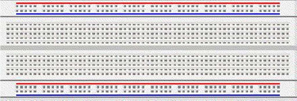
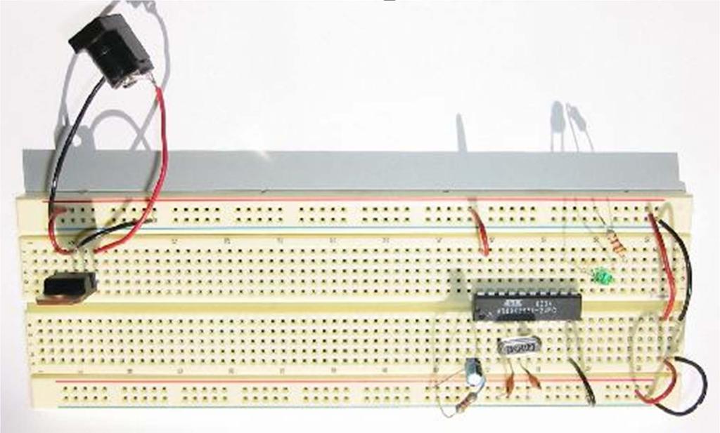
10 Experiment 1: Let us get started Figure 1.1: Internal Connections of Bread Board Figure 1.2: Sample Circuit with Chips on Bread Board Part II Build a 4-input AND gate using 2-input AND gates. Using the AND gate chip (7408) make the 4-input AND gate circuit. Connect 4 switches to the 4 inputs of the AND gate and an LED at the output of the gate. Lab Report Verify the truth table of 4-input AND gate. Submit the circuit of 4-input AND gate using 2-input AND gates and the truth table of 4- input AND gate. Page 4 Experiment 1
11 Experiment 1: Let us get started Page 5 Experiment 1
12 By: Masud-ul-Hasan Breadboard
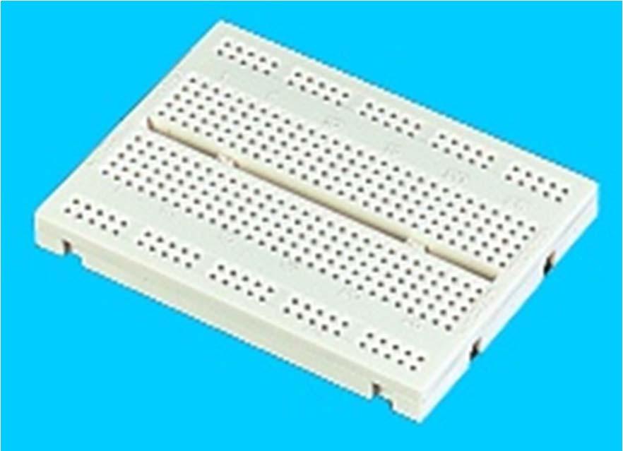
13 By: Masud-ul-Hasan Shape

14 By: Masud-ul-Hasan Connections

15 Connections Gap By: Masud-ul-Hasan
16 By: Masud-ul-Hasan Usage
17 Experiment 2: Prototyping of Logic Circuits using Discrete Components Experiment 2: Prototyping of Logic Circuits using Discrete Components Objectives In this experiment, you will learn: Binary addition using Full adder Building 4-bit adder ALU (Arithmetic Logic Unit) operation/capabilities Verification of 4-bit adder operation using ALU Building 8-bit adder using 2 cascaded 4-bit adders (2 ALUs) Material Required ICs 7408, 7432, 7486, Wires Wire Stripper Prototyping board with power and ground connections IC Tester Design Specifications You will construct a full adder circuit. The full adder is a common circuit used in many designs both small and large (including processors). The function of the full adder is quite simple add three, one-bit numbers. This may seem like a simple process, but the full adder is designed to be cascaded to compute addition on (arbitrarily) larger numbers. Your circuit must have three inputs, A, B, and Cin and two outputs, Sum and Cout. The block diagram is shown in Figure 2.1 below: A B Cin Full Adder Sum Cout Figure 2.1: Block diagram of the Full adder circuit Page 1 Experiment 2
18 Experiment 2: Prototyping of Logic Circuits using Discrete Components Following is the truth table of Full adder circuit: A B Cin Cout Sum Table 2.1: Truth Table of Full Adder By simplifying the two outputs Sum and Cout using any minimization scheme (K-Maps, Boolean algebra, etc), you will get: Sum= A B Cin Cout = AB + ACin + BCin Now implement the above two simplified Boolean equations on the breadboard using discrete components. The circuit diagram will be as follows: Figure 2.2: Circuit diagram of the Full adder circuit Page 2 Experiment 2
19 Procedure Experiment 2: Prototyping of Logic Circuits using Discrete Components This experiment will be developed in 2 main parts plus one bonus part: In part 1, a 1-bit full adder circuit will be implemented. In part 2, a 4-bit adder circuit will be built using an ALU. In part 3 (bonus), an 8-bit adder circuit will be built by cascading two ALUs. Part I In this part, a 1-bit full adder circuit will be built. Get the proper ICs (AND, OR, XOR) from the shelves. Test the ICs on the IC tester. Place the chips on the breadboard carefully. Connect the Vcc pins of the chips to the +5V on the board. Connect the GND pins of the chips to the GND on the board. Build your logic diagram by making appropriate connections as shown in Figure 2.2 Use 3 switches for the 3 inputs A, B, and Cin. Connect the two outputs Sum and Cout to 2 LEDs. Use the switches on the board to verify your circuit. The circuit of a Full adder can be cascaded to build a 4-bit adder as shown (below) in Figure 2.3. A3 B3 A2 B2 A1 B1 A0 B0 C0 Full Adder Full Adder Full Adder Full Adder C4 S3 C3 S2 C2 S1 C1 S0 Figure 2.3: Block diagram of a 4-bit adder circuit. Part II In this part, a 4-bit adder circuit will be built using an ALU. To avoid too many wiring, we will use the 4-bit adder as one of the available functions of ready made 4-bit ALU. Now use ALU on the breadboard. Connect Vcc and Gnd of to +5V and GND of the board respectively. Connect the four As (A3 A2 A1 A0) of to four switches. Connect the four Bs (B3 B2 B1 B0) of to other four switches. Connect M (mode) to the Gnd of the board. Connect C R to the Vcc of the board. Connect the four outputs F3 F2 F1 F0 of to the four LEDs. Connect C (Carry out) to another LED. Check the addition operation of ALU by making the select lines S3 S2 S1 S0 as (fix these values by connecting S3 and S0 to +5V while S2 and S1 to GND) Change the values of the A and B switches and verify the result on the LEDs. Page 3 Experiment 2
 of the first to carry in (C R ) of the second ALU.")
20 Experiment 2: Prototyping of Logic Circuits using Discrete Components Part III (Bonus) In this part, an 8-bit adder circuit will be built by cascading two ALUs. Extend your design to 8 bit adder circuit by cascading two chips and connecting the carry out (C) of the first to carry in (C R ) of the second ALU. Join select lines and M of both chips together. Fix the select lines of both ALUs S3 S2 S1 S0 to for addition function and M to Gnd of the board as in Part II. The first ALU will serve as lower nibble (half byte ) and second ALU will serve as higher nibble (half byte ). Due to limited number of switches, connect eight As (A7 A6 A5 A4 A3 A2 A1 A0) to eight switches. Connect eight Bs (B7 B6 B5 B4 B3 B2 B1 B0) to fix values (by connecting +5V and GND) like Connect the eight outputs F7 F6 F5 F4 F3 F2 F1 F0 of to the eight LEDs. Leave the carry out (C) of second ALU unconnected as no LED will be left. Change the values of As switches and verify the result on the LEDs. Table 2.2: Function Table of 4-bit ALU (74181) Lab Report Print the lab report format and write a complete lab report on this printed document about this experiment as mentioned in the document. Page 4 Experiment 2

21 Experiment 2: Prototyping of Logic Circuits using Discrete Components Bit ALU Page 5 Experiment 2
22 Experiment 3: Introduction to FPGA Experiment 3: Introduction to FPGA Objectives In this experiment, you will: Get introduced to FPGA board Get familiar with the ISE design suite and the ISim simulator Learn how to make design entry and bind I/O board switches and LEDS Design, simulate, and verify simple logic gates on board Material Required Spartan 3A board ISE design suite software Design Specifications In this experiment, you will be familiarized with the FPGA boards available in the lab. FPGA stands for Field Programmable Gate Array, which is a programmable chip that allows you to test and run, complicated logic designs. The FPGA board used in this lab is the Xilinx Spartan3A board. The design process starts with design preparation of the required logic circuit. Using ISE Design Suite, you will be able to: enter the design using schematic drawing simulate the design to verify its functionality download the configuration bits file of the verified design to the FPGA verify the design on board In this lab, you will make a design entry of a Half Adder. Then you will verify its functionality using the behavioral simulator ISim. Finally, you will assign the I/O (Input/Output) of the design to physical switches and LEDs of the board and program it. Page 1 Experiment 3
23 Procedure Experiment 3: Introduction to FPGA The procedure of this lab will be developed in 7 main parts; 1. In part 1, you will create and setup the project files and parameters in ISE design suite software. 2. In part 2, you will enter the design using Schematic drawing. 3. In part 3, you will simulate the design and verify its functionality. 4. In part 4, you will connect the inputs and outputs of the circuit to input and output pins in the FPGA board. 5. In part 5, you will generate the configuration bits file of the design. 6. In part 6, you will generate and analyze the post-place and route timing report. 7. In part 7, you will download the design configuration bits file to the FPGA board. 1. Create a New Project The objective here is to setup the project files and parameters. A project in ISE is a collection of all the files needed to create and download a design to the selected FPGA device. The project will be adapted to use the FPGA available on our board. The project allows us to draw a schematic as the main way of entering the design. Here are the steps for creating a new project: 1. Launch Xilinix ISE design Suite software 2. Select File, New Project. 3. In the New Project Wizard dialog box, type the desired location in the Project Location field, or browse to the directory under which you want to create your new project directory using the browse button next to the Project Location field. 4. Enter lab3 in the Project Name field. When you enter lab3 in the Project Name field, a lab3 subdirectory is automatically created in the directory path in the Project Location field. 5. Use the pull-down arrow to select Schematic from the Top-Level Source Type field. Click in the field to access the pull-down list. 6. Click Next. 7. In the New Project Wizard Device and Design Flow dialog box, use the pull-down arrow to select the Value for each Property Name. Click in the field to access the pulldown list. Make sure the values are as follows: Device Family: Spartan3A and 3AN Device: XC3S700A Package: fg484 Speed Grade: -4 Top-Level Module Type: Schematic Synthesis Tool: XST Simulator: ISim Preferred language: VHDL 8. When the table is complete, your project properties should look like Figure 1. Page 2 Experiment 3


24 Experiment 3: Introduction to FPGA Figure 1: Project Properties 9. Click Next. 10. Click Finish to create the project. A summary of the project will be shown as in Figure 2. A new project called lab3 is created and is shown on the left side panel under implementation tab. Figure 2: Summary of the Project 11. Right click on lab3 project and choose New Source. Select Schematic from the box on the left and type in a file name for your project such as halfadder. Click Next. Click Finish. A new Schematic file is created, click on symbol tab to show different symbols and logic gates Page 3 Experiment 3
25 2. Schematic Design Entry Experiment 3: Introduction to FPGA The objective here is to enter the design using Schematic drawing. You will design a simple half-adder using AND and XOR gates as follows, 1. Add a 2 input AND gate as follows, From the toolbar go to Add, click on Symbol. Or click the Add Symbol icon in the vertical toolbar to the left of the workspace (Looks like a gate with a resistor below it). Or simply click on symbols tab in the bottom of the design panel Select Logic from the list of Categories Select and2 from the list of Symbols Place one AND gate on the schematic. Click the left mouse button to place the gate on the schematic where the cursor sits Press Esc to exit Add Symbol mode and restore your select tool 2. Add a 2 input XOR gate as follows, Select Logic from the list of Categories. Select xor2 from the list of Symbols. Place one XOR gate next to the AND gate on the schematic. Click the left mouse button to place the gate on the schematic where the cursor sits. Press Esc to exit Add Symbol mode and restore your select tool 3. Adjust your view using the Zoom option (View, Zoom, In) and the scroll bars in the schematic window 4. Add I/O Markers: I/O markers are needed by the design tool to synthesize the design. They give a logical connection for the synthesis tool to understand that the internal signal will be passed outside either the chip or schematic. It is very important that the correct type of I/O marker be used. Putting an input I/O marker on an output pin will cause an error. Fortunately, ISE will automatically decide if the maker is input or output when it is connected to the pin. Select Add, I/O Marker. Or click the Add I/O Marker icon from the vertical menu bar Add input markers to the AND and XOR gates as follows, Place the cursor, which now displays the input graphic, at the end of the input wire To rename the I/O Marker, double click on the I/O marker and chose Nets from the left side. Type the name of the marker in the Value of the Name attribute. Or Right Click and choose Rename port Name the input markers of the AND gate A and B The input graphic is added to the end of the wire, around the net name Wire the inputs of the AND gate to the inputs of the XOR gate Select Add Wires from the vertical menu bar, and connect input I/O markers to the XOR gate as shown in Figure 3 Page 4 Experiment 3


26 Experiment 3: Introduction to FPGA Add an output marker to the output of the AND gate and another to the output of the XOR gates Select the Add an output marker radio button on the Options tab. Place the cursor, which now displays the output graphic, at the end of the output wire. Name the output marker of the AND gate C and the output of the XOR gate S Figure 3 Your schematic is complete. Save the schematic diagram using File -> Save or press on the Save icon on the toolbar. 3. Behavioral Simulation The objective here is to simulate the design to verify its functionality. ISE provides an integrated simulation flow with the ISim simulator that allows simulations to be run from the Xilinx Project Navigator GUI. We introduce the concept of simulation and how to verify the function of a circuit through behavioral simulation. 1. In the project navigator to the left, click on the Design tab, then click on your schematic file. Change to the simulation mode by selecting the Simulation radio button as shown in Figure 4. Figure 4 Page 5 Experiment 3

27 Experiment 3: Introduction to FPGA 2. Press on the + mark in front of ISim Simulator to expand the list. Right click on the Simulate Behavioral Model and choose Process Properties to change simulation attributes. Uncheck the mark in front of Run for Specified Time. This will not limit the simulation for a specific run time. Press OK. 3. To run the simulation, double click on Simulate Behavioral Model, or right click and press Run. 4. ISE will launch ISim in a separate window. If it didn t, refer to the lab manual to check the error logs and how to correct them. Note that the simulation will fail to run if a current process of ISim is working, close any instance of ISim before running any simulation. 5. ISim will launch automatically. The wave window displays the signals, buses and their waveforms. Note that there are four signals shown; A, B, S, and C. Figure 5 6. Right click on input A in the objects window, and choose Force clock. Add the following values: a) Leading Edge Value: 0 b) Trailing Edge Value: 1 c) Period: 1 us 7. Alternatively, you can write the following Tcl command in the console window: a) isim force add A 0 -value 1 -time 500 ns -repeat 1 us 8. Similarly, right click on input B in the objects window and choose Force clock. Add the following values: 9. Alternatively, you can write the Tcl command in the console window, a) Leading Edge Value: 0 Page 6 Experiment 3

28 Experiment 3: Introduction to FPGA b) Trailing Edge Value: 1 c) Period: 0.5 us 10. Alternatively, you can write the Tcl command in the console window, isim force add B 0 -value 1 -radix bin -time 250 ns -value 0 -radix bin -time 500 ns - value 1 -time 750 ns -repeat 1us 11. Enter 1 us inside the simulation time toolbox in the toolbar, and then press Run for the Time Specified in the Toolbar icon. Or type the following Tcl command in the console window. Run 1 us 12. The simulator will show the behavior of the gates according to the specified input signals, press in Zoom to Full View in the toolbar to show the entire simulation period. 13. The simulator will show the behavior of the gates according to the specified input signals, press in Zoom to Full View in the toolbar to show the entire simulation period. You can Zoom in and Zoom out using the icons in the toolbar. Your signals should look like the following: Figure To restart the simulation, press on Restart icon on the toolbar. Note that restarting the simulation will also remove the force clock values. You have to apply force clock to the input signals before running the simulation again. 15. Verify that the circuit is working correctly by checking the time diagram (waveform) as shown in Figure Close ISim and return to ISE. Page 7 Experiment 3
 to 2 of the output pins of FPGA chip which are connected to board LEDs.")
29 4. Package Pins Assignment Experiment 3: Introduction to FPGA The objective here is to connect the inputs of the circuit (A & B) to 2 of the input pins of the FPGA chip which are connected to board switches. Likewise, we want to connect the output of the circuit (S & C) to 2 of the output pins of FPGA chip which are connected to board LEDs. This will allow us to manually test the circuit on the board. Switches and LEDs on the FPGA board are connected as follows: 1. Choose input and output pins on your Digital Logic Board. See appendix A in the Lab Guide for the pins diagram. Refer to Appendix B in the Lab Guide to find which pins of the chip FPGA are connected to the board switches and LEDs. Pick two switches (inputs) and two LEDs (outputs). 2. In the project navigator to the left, click on the Design tab. Then click on your schematic file. Change to implementation mode by selecting the Implementation radio button on top. 3. Click on I/O Pin Planning (Plan Ahead) Post-Synthesis under User Constraints. This will launch PlanAhead. 4. In PlanAhead, select the I/O Ports tab in the left panel, expand Scalar ports. You will find a list of the I/Os of your schematic design, i.e., {A, B, S, and C}. 5. Decide the site number of the switch(es) and LED(s) for inputs and outputs on your board (represented by a small code on the board). In this guide, we are using SW0, SW1, LD0, and LD1 which have the sites v8, u10, r20, and t19, respectively. 6. Click on the I/O port, then click the column under Site on front of the I/O port and choose the corresponding site from the drop down list. Do it for A, B, S, and C. Figure 7 7. Once the pins are locked down, select File Save Design. The changes made in PlanAhead are saved in the lab3.ucf file in your current working directory. 8. Exit PlanAhead. Page 8 Experiment 3
30 5. Design Implementation Experiment 3: Introduction to FPGA The objective here is to generate the configuration bits-file which, when downloaded to the FPGA chip, configures it to implement our specific design. Note: For more information about implementing a design, see ISE Help. Select Help, ISE Help Contents, expand either the FPGA or CPLD hierarchy in the left pane and expand the Implementing Design hierarchy. 1. Click on your schematic file in the project navigator. 2. Double-click on Generate Programming File in the Processes window. This runs all processes and creates the configuration bits file of this design. Be patient this takes a while! 3. The BitGen program creates the (halfadder.bit bitstream file. The bitstream file contains the actual configuration data. 4. A check on the Processes for Source window denotes a process that was run successfully. An exclamation sign indicates that the process was run and that there is a warning for the process. More information about warnings can be obtained in the Transcript window. 6. Timing Analysis The objective here is to analyze the time report of the implemented design. To see the timing report, go to Tools->Timing Analyzer->Post-Place & Route. The timing report will be shown in the right window similar to Figure 8 Figure 8 Programming the Spartan Board Page 9 Experiment 3
31 7. Board Programming Experiment 3: Introduction to FPGA The objective here is to download the design configuration bits file to the FPGA board. The detailed procedure is as follows, 1. Turn on your Xilnix Spartan-3AN Board and make sure that the board cable is properly connected to the PC. 2. Double-click Generate Programming File to create a bitstream of your design 3. The BitGen program creates the halfadder.bit (a bitstream file). The bitstream file contains the actual configuration data. 4. Click on Configure Device to expand the list, then double click on Generate Target PROM/ACE File. A pop-up window will appear, click OK. 5. ISE will automatically run impact. Double-click on Boundary Scan Mode in the impact Flows box on the left. 6. Right-click in the middle of the white window to initialize new JTAG chain. Choose Initialize Chain. This will create and show a device chain. Click Yes if it asks to continue and assign configuration files. 7. Choose the halfadder.bit file you generated in the proper directory. Click Open. Click No to attach SPI or BPI PROM. 8. A window will appear Add PROM File, choose Cancel. 9. Another window will open, this time click Bypass. Then click OK. 10. A window will appear Device Programming Properties, click OK. 11. Right-click on the first chip, named xc3s700a, and choose Program. When the program operation completes, a blue message with Program Succeeded appears. 12. Congratulation, your design is programmed in the Xilnix board. Go and have fun with it. You should be able to verify the design of the circuit using switches and LEDs. 13. Show your design to the lab instructor. 14. When you close the program, it will ask you to Save current project before exiting ISE IMPACT. Click NO. 15. Turn off your Xilnix Spartan-3A board after showing it to the instructor. 16. Follow the same steps that you have done with the instructor and make a 1-bit full adder circuit. Simulate it using ISim and test it on FPGA board. Lab Report Print the lab report format and write a complete lab report on this printed document about this experiment as mentioned in the document. Submit the printed circuit diagram of full adder, simulation screen shot and timing report as an attachment with the lab report. Page 10 Experiment 3

32 Experiment 4: Creating and Using Symbols Experiment 4: Creating and Using Symbols Objectives In this experiment, you will: Get more familiar with FPGA and design tool Learn about symbols and hierarchical design Build Half-Adder and define it as a symbol Use the Half-Adder symbol to build a Full-Adder, and define a symbol for it Build a 4-bit adder using Full-Adder symbols Material Required Xilnix FPGA board ISE design suite Design Specifications In experiment 2, you have constructed a full-adder using IC circuits and verified it using a prototype board. This week, you will use FPGA board to design, simulate and verify different circuits. First, you will build a Half-Adder (HA). The function of the Half-Adder is to add 2 input bits. Thus, the half-adder has only two inputs and two outputs. The circuit diagram and the truth table of the half-adder are shown in figure 1 and figure 2. You will create a symbol of this circuit and name it as HalfAdder. A B S C Figure 1: Logic diagram of half-adder Table 1: Truth table of half-adder Page 1 Experiment 4

33 Experiment 4: Creating and Using Symbols Then you will design a full-adder (FA) using the symbol you created. You might already know that full-adder adds three bits and produces two output bits. Figure 2 shows the circuit diagram of the full-adder. Note that you need two half-adders and one 2-input ORgate. Similarly, you will create a symbol for the full adder to be used as one unit and call it FullAdder. Figure 2: Logic diagram of a 1-bit full-adder Finally, using N full-adders, you can create a circuit that adds two N-bit numbers. The carryin of each Full Adder is the carry-out of the previous Full Adder. This type of adder is called a ripple carry adder (RCA). In this lab, you will build a 4-bit binary adder using the four 1-bit full-adder symbols you have created previously. The logic diagram of the 4-bit adder is shown in Figure 3. A3 B3 A2 B2 A1 B1 A0 B0 C0 Full Adder Full Adder Full Adder Full Adder C4 S3 C3 S2 C2 S1 C1 S0 Figure 3: Logic diagram of a four-bit adder Procedure The procedure of this lab is divided into 5 main parts as follows, 1. In part I, you will build and verify a Half-Adder circuit 2. In part II, you will build a symbol of Half-Adder 3. In part III, you will build a Full-Adder using Half-Adder symbols 4. In part IV, you will build a Full-Adder symbol 5. In part V, you will build a 4-bit adder using Full-Adder symbols Note: you may refer to the lab guide for detailed step-by-step procedure Page 2 Experiment 4
34 Part I Experiment 4: Creating and Using Symbols Objective: Build and verify the operation of the H.A. circuit 1. Start ISE Design Suite, Create a new project. Choose Schematic as Top-level source type and set project settings properly (Section II part 1 in lab guide). 2. Create a new source of type Schematic and name it HalfAdder 3. Draw the logic diagram of the half-adder in the schematic editor window as shown in Figure 1 4. Append I/O markers properly. Name the inputs A and B, and the outputs, S and C 5. When you finish, save and run the behavioral simulator Isim 6. Use the following Tcl commands to add force clock to the inputs (or do it through Force Clock method as you have done before in previous experiment). isim force add {/HalfAdder/A} 0 -radix bin -value 1 -radix bin -time 500 ns -repeat 1 us isim force add {/HalfAdder/B} 0 -radix bin -value 1 -radix bin -time 250 ns -repeat 500 ns 7. Run the simulation for 1 us, then verify the output signals. Close ISim if your design entry simulation is correct. Otherwise, go back and correct the mistakes, if any. 8. Choose any of the board switches and LEDs and note down their site numbers. Using PlanAhead, assign I/O ports in your design entry to the selected switches and LEDs. 9. Generate Bit file, and Program your board. 10. Verify half-adder functionality on the board. Part II Objective: Define a higher level symbol of the H.A. 1. To create a symbol of your half-adder, in ISE Schematic Editor, go to Tools- >Symbol Wizard 2. Click on Using schematic options and choose your schematic file from the dropdown list. Click Next. 3. Edit Symbol name, name it HalfAdder. Make sure that all pin definitions are correct. Click Next. 4. Click Next on the layout page, then Finish in the Preview page 5. Now your symbol is already added to the symbol library in your project. You can find it under categories (will have the long path of your file) or simple type its name in Symbol name filter. Page 3 Experiment 4
35 Part III Experiment 4: Creating and Using Symbols Objective: Build a F.A. using H.A. symbol 1. Create a new source (of type Schematic) and name it FullAdder. 2. Draw the logic diagram of the full-adder in the schematic editor window, as shown in Figure 2, using the H.A symbol created in Part II. 3. Append I/O markers properly. Name the inputs A, B, and Cin, and the outputs, S and Cout. 4. When you finish, save and run the behavioral simulator Isim. 5. Use the following Tcl commands to add force clock to the inputs (or do it through Force Clock method as you have done before in previous experiment). isim force add {/FullAdder/A} 0 -radix bin -value 1 -radix bin -time 1000 ns -repeat 2 us isim force add {/FullAdder/B} 0 -radix bin -value 1 -radix bin -time 500 ns -repeat 1 us isim force add {/FullAdder/Cin} 0 -radix bin -value 1 -radix bin -time 250 ns -repeat 500 ns 6. Run the simulation for 1 us and then verify the output signals. Close ISim if your design entry simulation is correct. Otherwise, go back to your design entry and correct any mistakes. 7. Choose any of the board switches and LEDs and note down their site numbers. Using PlanAhead, assign I/O ports in your design entry to the selected switches and LEDs. 8. Generate Bit file, and Program your board. 9. Verify full-adder functionality on the board. Part IV Objective- Define a F.A. symbol 1. To create a symbol of your full-adder, in ISE Schematic Editor, go to Tools- >Symbol Wizard 2. Click on Using schematic options and choose your schematic file from the dropdown list. Click Next. 3. Edit Symbol name, name it FullAdder. Make sure that all pins definitions are correct. Click Next. 4. Click Next on the layout page, then Finish in the Preview page 5. Now your symbol is already added to the symbol library in your project. You can find it under categories (will have the long path of your file) or simple type its name in Symbol name filter. Page 4 Experiment 4
36 Part V Experiment 4: Creating and Using Symbols Objective: Build a 4-bit adder using F.A. symbols 1. Create a new source of type Schematic and name it fourbitadder 2. Draw the logic diagram of 4-bit adder in the schematic editor window, as shown in Figure 3, using F.A symbol created in Part IV 3. Append I/O markers properly. Name the inputs A0, A1, A2, A3, B0, B1, B2, and B3 accordingly. Name the outputs S0, S1, S2, S3, and Cout. 4. Connect the first carry in C0 to ground (gnd) to make it permanently zero. 5. When you finish, save and run the behavioral simulator Isim 6. Verify the simulation results using proper input signals. You should test different input signals to ensure correct functionality of the adder. 7. Choose any of the board switches and LEDs and note down their site numbers. Using PlanAhead, assign I/O ports in your design entry to the selected switches and LEDs 8. Generate Bit file, and Program your board. 9. Verify 4-bit full-adder functionality on the board. Lab Report Print the lab report format and write a complete lab report on this printed document about this experiment as mentioned in the document. Attach all the three simulation snapshots and all the circuit diagrams. Page 5 Experiment 4
 The bouncing problem Solving the bouncing problem with a debouncing circuit Material Required PC with Xilinx software installed FPGA Board Debouncing circuit block LCD")
37 Experiment 5: Introduction to Sequential Circuits Experiment 5: Introduction to Sequential Circuits Objectives In this experiment, you will learn about: Sequential circuits Counter circuits The use of Liquid Crystal Display (LCD) The bouncing problem Solving the bouncing problem with a debouncing circuit Material Required PC with Xilinx software installed FPGA Board Debouncing circuit block LCD Display block and other related files Design Specifications Sequential Circuits: A combinational circuit is a circuit whose outputs depend only upon the present inputs but a sequential circuit is a circuit whose outputs depend upon present input as well as past inputs. In other words, the outputs of the circuit have sequential behavior. An example of such a circuit is a binary counter. In a binary counter, the output is incremented or decremented by 1 with each clock pulse and therefore the new output always depends upon the previous output of the circuit along with the clock pulse. Figure 5.1: Block diagram of combinational circuit Page 1 Experiment 5

38 Experiment 5: Introduction to Sequential Circuits Sequential circuits are important because only combinational logic is not enough for synthesizing a sophisticated digital system. A sequential circuit is nothing but the conjunction of a combinational circuit along with a storage facility or memory element. The memory element stores the past values of the outputs of the circuit and thus provides a way to feed them back to the circuit as inputs. Figure 5.2: Block diagram of sequential circuit Examples of sequential circuits are counters, registers, sequence detectors, traffic signal controllers, vending machines, etc. One requirement common to many digital circuits is counting, both forward and backward. Examples include digital clocks and timers watches which are found in a range of appliances from microwave ovens, washing machines, to automobiles. Here we are going to use a 4-bit binary (Mod-16) counter circuit available in the Xilinx software library. Procedure This lab is divided into three main parts: I. Study of a counter circuit operation using manual clock push button and recognizing the bouncing problem. II. Use of a debouncing circuit to solve the bouncing problem. III. Use of the FPGA board LCD display (instead of LEDs) to display the output of the counter. Page 2 Experiment 5
39 Experiment 5: Introduction to Sequential Circuits Part I -Study of bouncing problem by using a counter circuit. In this part of the experiment, a 4-bit up counter will be used with manual clocking to observe the bouncing problem of the manual clock push button. Start a new project. Get a 4-bit counter CB4CE (with clear CLR and chip enable CE) from the library of Xilinx software in your schematic drawing. Connect the clock input Clk to a push button. Connect the clear input CLR to another push button. Connect the CE to VCC to make it enabled all the time. Connect the five outputs Q0, Q1, Q2, Q3, and CEO to five LEDs in such an order that Q0 should be the least significant bit. Now test your circuit by pressing the manual clock push button. It should count up from 0 to 15 in binary on 4 LEDs. Clear should make the count 0 whenever it is pressed. While compiling the project if manual clock gives any error then you have to add the following command as the last command in your.ucf file by double clicking on.ucf file: NET CLK CLOCK_DEDICATED_ROUTE = FALSE; Even though the counter should count up one time when the clock push button is pressed only once, observe that it actually counts up by more than one due to bouncing problem. Figure 5.3: 4-bit Counter with Chip Enable and Clear Page 3 Experiment 5
40 Bouncing Problem: Experiment 5: Introduction to Sequential Circuits A big problem with mechanical switches (especially push buttons) is that when the switch is moved to a new position it strikes the metal contact and physically bounces a few times due to elasticity. This is called contact bounce or simply bouncing problem. Figure 5.4: Bouncing problem of a mechanical switch If a switch is to turn on a lamp or start a fan or motor, then contact bounce is not a problem because these devices are slow. But if a switch is used as input to a digital counter, a personal computer, or a micro-processor based piece of equipment, then contact bounce must be considered. The reason for concern is that the time it takes for contacts to stop bouncing is measured in milliseconds and digital circuits can respond in nanoseconds. Solution: To solve this problem there are different ways which are called debouncing. We are solving it here by using a piece of code written in Verilog language. It is basically a counter. The logic used is that when this counter detects the first transition (change in the position of switch), it starts counting 50,000 cycles of the on board clock (50 MHz) to create a delay before it outputs the final value of the switch. This delay time is enough for the bounces to disappear. How to use it? It is very simple. Just add Verilog file debouncing.v to the project. Create a symbol of it as shown in the Figure 5.5and use it. It has two inputs; the noisy signal (noisyclk) and the system clock (sysclk). The output is the clean version of the noisy signal. Connect push button that you are using for manual clock to the noisy clock and system clock (E12) of the FPGA board to the system clock input of the debouncing circuit. Connect output (cleanclk) to the clock input of your circuit. Page 4 Experiment 5


41 Experiment 5: Introduction to Sequential Circuits Figure 5.5: The symbol of debouncing circuit Part II - Solving of the bouncing problem with a debouncing circuit. In this part, a special circuit will be used to solve the bouncing problem. Get the debouncing.v file from WebCT and add source to your project. Create a symbol of it. Add the debouncing symbol in your circuit as shown in the figure. Delete the Clk input pad from the circuit and connect cleanclk to the clock of the counter. Edit the.ucf file as mentioned above. Sysclk should be the system clock E12 and noisyclk should be the push button. Now test your circuit by pressing the manual clock push button. It should count up from 0 to 15 in binary on 4 LEDs without any bouncing problem. Figure 5.6: Counter with debouncing circuit Page 5 Experiment 5
 and the.ucf file from WebCT and copy these in your project folder.")
42 Part III Use of LCD Display Experiment 5: Introduction to Sequential Circuits In this part of experiment, an LCD block (code) will be used to show the results on LCD display instead of LEDs. Delete the five output pads of the counter circuit. Get the LCD related Verilog file (.v) and the.ucf file from WebCT and copy these in your project folder. Add the Verilog file to your project (by add source) and then make the symbol of it. Add this symbol in your circuit in such a way that the five inputs naming I0, I1, I2, I3, I4 of LCD_block should be connected to the 4 Q outputs and CEO output of the counter. Connect the clock of LCD_block to the system clock. Connect the reset of LCD_block to the clear of counter. Add the output pads to all the outputs of this block and name these pads with the same names of the outputs of the block as shown in the figure. Edit the.ucf file by adding the commands at the end of your.ucf file which are given in the.ucf file downloaded from webct. Now test your circuit by pressing the manual clock push button. It should count up from 0 to 15 in Decimal on LCD display. Lab Report Figure 5.7: LCD_block added to the circuit. Print the lab report format and write a complete lab report on this printed document about this experiment as mentioned in the document. Page 6 Experiment 5

43 Experiment 6: Clock and Clock Frequency Experiment 6: Clock and Clock Frequency Objectives In this experiment, you will: Learn the concept of clock and clock frequency Learn how to use oscilloscope Construct a circuit to generate lower frequency clocks using counters Learn the concept of carry out and count enable Use multiplexers to choose among different clock frequencies Use of buses and bus taps Material Required PC with Xilinx software installed Spartan3AN FPGA board CC16CE (4-bit Counter) and M4_1E (4 X 1 MUX) symbols Oscilloscope Design Specifications 1. Clock signal Sequential circuits are controlled by a periodic control signal, called the clock. This signal allows memory elements to change their states at either the rising or the falling edges of this signal (Figure 6.1). This clock signal is generated by a built-in clock on the FPGA board. 1 Rising clock edge Falling clock edge 0 Clock Period = T seconds Clock frequency = # of clock cycles / seconds = Figure 6.1: Clock signal Spartan3A FPGA has a global built-in clock frequency of 50 MHz (20 ns period). This clock is too fast to be monitored with human eyes. Thus, we need a circuit to reduce this frequency to lower frequencies that we can observe using human eyes. In this lab, you will design a clock division circuit that reduces this frequency to different slower frequencies. Page 1 Experiment 6

44 Experiment 6: Clock and Clock Frequency You will observe the clock signal from your board using an electronic test instrument called oscilloscope. A typical oscilloscope, Figure 6.2, is divided into four sections; the display, vertical controls, horizontal controls, and trigger controls. A probe is connected with oscilloscope from one end and to the output you want to monitor on the other end. In this lab, you will probe an output pin on your board to monitor the 50 MHz signal. Figure 6.2: Oscilloscope 2. Frequency division Consider a 2-bit counter (also known as Mod4 counter), the counter count sequence is shown in Figure 6.3. The period of the Q 0 signal is double the period of the clock, i.e. frequency of Q 0 =. Similarly, the period of the Q 1 signal is four times the period of the clock, i.e. Q 1 =. Thus we can effectively use Q1 bit to generate a clock that is divided by 4, as shown in Figure 6.3. Figure 6.3: Clock, Q 0, and Q 1 signals Generally speaking, we can divide a clock by 2 n if we take the output clock from the n th -bit of an n-bit counter. A simple equation for finding the value of n to generate 1.5 Hz clock is as follows, 50 MHz/2 n 1.5 Hz After calculation, n is found to be 25. Since the largest counter available in Xilinx library is 16-bit counter (e.g. CC16CE), we need to cascade two 16-bit counters. Cascading is done by exploiting CEO (Chip Enable output) signal. CEO is at logic high when the counter reaches its highest count (i.e. FFFF) as shown in Figure 6.4. CEO pin is connected to CE (Chip Enable) pin on the next counter to activate the counter as shown in Figure 6.4. The two counters share the same clock source. The 1.5 Hz clock signal is taken from the 9 th output of the second 16- bit counter. The 8 th pin will provide a clock signal of 3 Hz and so on. Page 2 Experiment 6

45 Experiment 6: Clock and Clock Frequency Figure 6.4: CEO signal of a 4-bit counter 3. Multiplexer Figure 6.5: 1 Hz frequency division circuit Multiplexer is a circuit that has 2 n inputs and a single output. Only one of the 2 n inputs is passed to the single output based on the value of n-bit select inputs. The truth table and graphic symbol of a 4-to-1 multiplexer is shown in Figure 6.6, where I 0, I 1, I 2, and I 3 are the inputs, and S 0 and S 1 are the select lines. In part III, you will use the output of a 4-to-1 multiplexer to choose from four different frequencies (i.e. 1.5 Hz, 3 Hz, 6 Hz, and 12 Hz) generated by the frequency division circuit. The output of the multiplexer will be connected to one of board LEDs. To observe different frequencies, you will use two switches connected to the input select lines to pass signals with different frequencies to the LED. I 0 I 1 I 2 I 3 S 1 S 0 Out Inputs Output S 1 S 0 I 3 I 2 I 1 I 0 Out 00 X X X X X X X X 0 X 0 01 X X 1 X 1 10 X 0 X X 0 10 X 1 X X X X X X X X 1 Figure 6.6: Truth table and graphic symbol of 4x1 multiplexer Page 3 Experiment 6

46 Procedure Experiment 6: Clock and Clock Frequency 1. In part I, you will observe the FPGA board main clock signal using oscilloscope 2. In part II, you will build the frequency division circuit 3. In part III, you will observe the different frequency signals using a 4-to-1 multiplexer Part I Objective- To observe the FPGA board main clock signal using oscilloscope 1. Start ISE Design Suite and create new project 2. Create a new source of type Schematic, call it (Oscilloscope), and draw the circuit shown in Figure Choose BUF from the symbol list and place it on your schematic window 4. Place I/O markers properly and name it as shown 5. Start Plan Ahead software and assign site E12 to Clock and V14 (upper-most pin of accessary header J20 as shown in Figure 6.8) to Output. Note: output is a reserved word so make O capital. 6. Generate the Bit-file, and Program your board 7. Place the probe from your oscilloscope on the Output pin (V14) and ground of probe to the GND of J20. Observe the clock signal output on your oscilloscope screen. You should get a waveform with frequency of 50MHz on your oscilloscope screen Figure 6.7: Circuit for Testing With Oscilloscope Prob Figure 6.8: Accessory Header J20 and Location of V14 Ground of Prob Part II Objective- To build a frequency division circuit 1. Create a new source of type Schematic, name it (OneHz), and draw the circuit shown in Figure Choose CC16CE 16-bit counter and place two of them on your schematic window. 3. Place VCC, GND and I/O markers properly. Name the input marker to the first counter as clock. 4. Wire the two counters as shown. Name the wire connecting the CEO pin of the first counter to the CE pin of the second counter as CountEnable. Page 4 Experiment 6
47 Experiment 6: Clock and Clock Frequency 5. The output of the last counter is a bus of 16-bits. Name the output markers with Q(15:0). 6. Start ISim. Apply a clock signal to clock input with a leading edge value of 0, trailing edge value of 1 and Period of 20 ns (50 MHz). 7. Run the simulation and observe the wave signals on clock, countenable and Q. You should run the simulation for a long time (2s or more) to observe the change in pin Q9. Verify that your circuit is correct. 8. Close ISim if your design entry generated the expected output wave signals. 9. Create a symbol of your frequency divider circuit, name it (OneHz), and save it (refer to the lab guide for how to create a symbol). Part III Objective- To observe the different frequency signals using a 4-to-1 multiplexer 1. Create a new source of type Schematic, name it (MUX), and draw the circuit as in Figure 6.9 a. Choose M4_1E 4-to-1 multiplexer and place it on your schematic window b. Find the symbol OneHz you created in part II and place it on your schematic window c. Connect VCC to the enable (E) pin of M4_1E. Place I/O markers properly and name them as shown in Figure 6.9. d. Extend a wire out from the output of the OneHz symbol. Note that the wire is automatically widened. The wire is actually a bus. e. To rename the bus, click on the bus at your schematic draw and then click on Rename Selected Bus in the vertical toolbar. Click on Rename the branch then type Q(15:0) in the New Base Name of Bus then click Apply then OK. f. Double-click on the bus to make sure that the name is applied. If not then redo step e. 2. To get different frequencies from the frequency division circuit (OneHz), you need to properly choose the pin that gives the required frequency. For example, pin 9 will provide frequency of 1.5 Hz. Pin 8 provides frequency of 3 Hz and so on. You need to create Bus Tap in order to wire the output pins to the output bus of OneHz symbol as follows: a. Click on the Add Bus Tap icon in the vertical toolbar, or click Add->Bus Tap, set the orientation to Right. b. Click on the bus in your schematic draw once. The Selected Bus Name will be Q(15:0) c. Using the left and right arrows under Net Name, choose Q(9) one tap to the bus as shown in the Figure 6.9. d. The net name will be decremented automatically to Q(8). Place three more bus taps below the first tap (you will place Q(8), Q(7), and Q(6)). e. Connect each tap to the inputs lines of the M4_1E in proper order. f. Click on Net Name in the vertical toolbar and choose Name the branch from the menu to the left. g. Using left and right arrows under Name to choose Q(9). Click on the first wire you draw in step c to give the wire net name. h. Similarly, name the rest of the wires Q(8), Q(7), and Q(6) as shown in the Figure 6.9. Page 5 Experiment 6
 to your clock input.")
48 Experiment 6: Clock and Clock Frequency i. Double-click on each wire to ensure that they are named correctly 3. Run the simulation for enough time. Apply different inputs to SW1 and SW0 and verify that the output at LED0 is correct 4. Start PlanAhead and assign the board clock (E12) to your clock input. Connect LED0, SW0, and SW1 to proper sites on your board 5. Generate the Bit-file, and Program your board 6. Verify the output on the LED on your board by toggling the input switches 7. Turn off your board and Close ISE design suite Figure 6.9 The Final Circuit Lab Report Print the lab report format and write a complete lab report on this printed document about this experiment as mentioned in the document. Also make a table as shown below and write the proper values in it. SW0 SW1 Bus Tap Frequency 0 0 Q( ) Hz 0 1 Q( ) Hz 1 0 Q( ) Hz 1 1 Q( ) Hz Page 6 Experiment 6
49 Experiment 7: Synchronous and Asynchronous Counters Experiment 7: Building a Timer Circuit Objectives In this experiment, you will: Learn the difference between synchronous and asynchronous counter reset Learn how to use count-enable (CE) and count-enable-out (CEO) signals Build synchronous / asynchronous Modulo-10 Build Modulo-6 and Modulo-12 counters Build Modulo-60 counter Build a (hours, minutes, seconds) timer Learn about comparator circuit Build a circuit to get a lower frequency of 1KHz and 1Hz from 50MHz Learn about the clock without any gating Use LCD to display the timer circuit output Material Required PC with Xilinx software installed Spartan3AN FPGA board CB4CE (4-bit counter with asynchronous clear), CB4RE (4-bit counter with synchronous clear), COMP16 (16-bit comparator), constant and few gate symbols LCD Verilog files provided by instructor Design Specifications 1. Synchronous clear and asynchronous clear Some counters are provided with a Clear control input. With this capability, the counter can be cleared (be put in the all 0s state) when the clear input is activated. There are two types of Clear inputs; Synchronous and Asynchronous. When a Synchronous Clear input is activated, the Clear-ing action does not take place immediately but rather Clear-ing is delayed till the arrival of the next clock pulse (Clearing is synchronized with the clock signal). Conversely, when an Asynchronous Clear input is activated, the Clear-ing action is activated immediately without waiting for the next clock pulse (Clearing is NOT synchronized with the clock signal). Page 1 Experiment 7
50 Experiment 7: Synchronous and Asynchronous Counters 2. Synchronous and Asynchronous Modulo-10 Counter The CE input of a counter is a Count Enable signal that should be active for the counter to count; otherwise the counter maintains its count without change irrespective of the number of received clock pulses. Modulo-10 counter (also called BCD counter) is a counter that has 10 possible states; counting from 0 to 9 then back to 0. A modulo-10 counter can be built using a 4-bit (modulo-16) binary counter. To do this, the counter is cleared to its initial value 0000 after the counter reaches a count of 9 (1001 in binary) and maintains this value for a full clock period. For counters with Synchronous clear input, this is achieved by detecting the count 9 (1001 in binary) using an AND-gate. The output of this AND gate is then used as the clear input to the Mod-16 binary counter. Once the count of 9 is detected, the clear input = 1 which clears the counter when the NEXT clock pulse is received. For counters with Asynchronous clear input, this is achieved by detecting the count 10 (1010 in binary) using an AND-gate. The output of this AND gate is then used as the clear input to the Mod-16 binary counter. Once the count of TEN is detected, the clear input = 1 which clears the counter IMMEDIATELY. 4-bit cascadable binary counter with clock enable and synchronous clear symbol (CB4RE) is used to design Mod10 synchronous clear counter. The counter is cleared in the next clock cycle. Hence, state 10 will be active until the next clock cycle as shown in Figure 1. The waveform is shown in Figure 2. 4-bit cascadable binary counter with clock enable and asynchronous clear symbol (CB4CE) is used to design Mod10 asynchronous clear counter. The counter is cleared once Q1 and Q3 are high as shown in Figure 3. The waveform is shown in Figure 4. CEO pin is used to signal when the counter reaches its maximum count. CEO is active high when counter reaches count 9 in Synchronous clear counter. In Asynchronous clear counter, CEO is active high when counter reaches 10. Figure 1: Synchronous clear Modulo-10 counter Page 2 Experiment 7


51 Experiment 7: Synchronous and Asynchronous Counters Figure 2: Waveform of modulo-10 synchronous clear counter Figure 3: Asynchronous clear Modulo-10 counter Figure 4: Waveform of modulo-10 asynchronous clear counter Figure 5: Synchronous clear Modulo-10 counter with manual and auto-reset Page 3 Experiment 7
52 Experiment 7: Synchronous and Asynchronous Counters 3. Modulo-6, Modulo-12, and Modulo-60 Counters Similar to modulo-10 counter, modulo-6 and modulo-12 counters can be built using modulo-16 counters by choosing the proper inputs of the AND gate to clear the counter. Modulo-60 counters can be built using cascaded modulo-10 (for the least significant digit LSD) and modulo-6 (for the most significant digit MSD) counters. The Chip Enable Output (CEO) signal of the modulo-10 counter is connected to the Count Enable (CE) pin of the modulo-6 counter. Note that the CEO is ANDed with the main CE. Thus, the modulo-6 counter (MSD) digit is incremented once every 10 counts of (LSD). The CEO signal of modulo-60 counter is obtained by ANDing the CEO of modulo-10 and CEO of modulo-6 counters, i.e. CEO is active high when MSD is 5 and LSD is 9 (59). The circuit diagram of the modulo-60 counter is shown in Figure 6. Figure 6: Modulo-60 counter circuit diagram 4. Timer and LCD display Using the developed modulo-60 and modulo-12 counters, you will build a timer for hours, minutes, and seconds (HH:MM:SS). You need to cascade two modulo-60 counters and one modulo-12 counter to build the timer. Using the provided LCD Verilog file, you need to instantiate the LCD symbol provided in your Schematic to display the time on the board s LCD display. The LCD module has 20 data inputs that should receive the BCD digits of the hours, minutes and seconds from the counters as shown in Figure 10. Page 4 Experiment 7
53 Experiment 7: Synchronous and Asynchronous Counters 5. 1Hz and 1 KHz pulse generator The clock pins of all modules must be only connected to the FPGA board system clock. We need to build a 1 Hz (clock period of 1s) and a 1 KHz (clock period of 1 ms) pulse generator to enable the symbols. This can be done using a 16-bit counter with clock enable and asynchronous clear and a 16-bit comparator. The pulse is generated if the count reaches a specific constant. The constant is a 16-bit number that corresponds to a specific clock period. The FPGA board system clock has a frequency of 50 MHz, clock period of 20ns. To derive a clock period of 1ms (1KHz Frequency), the constant must be 1ms/20ns = (50000) 10 = (C350) 16 Using the 1KHz pulse generator, 1Hz pulse generator can be built by dividing the period by (1000) 10 = (03E8) 16 (since 1KHz = 1000Hz) Figures 7 and 8 show the 1 KHz and 1 Hz pulse generators, respectively. Note that the 16-bit counter in Figure 7 is clocked by the FPGA board system clock and enable with Vcc. While the 16-bit counter in Figure 8 is also clocked by the FPGA board system but enabled by the 1 KHz signal of Figure 7. Figure 7: Generating a 1 KHz pulse Figure 8: Generating a 1 Hz pulse Page 5 Experiment 7
54 Procedure Experiment 7: Synchronous and Asynchronous Counters The procedure in this lab is divided into four main parts: 1. In part I, you will build a 1Hz, and 1KHz pulse generator to be used as Enable signal for the counters. 2. In part II, you will build and create symbols of modulo-10, modulo-6, and modulo-12 counters. 3. In part III, you will build modulo-60 counter. 4. In part VI, you will build hours, minutes, and seconds timer and display time on LCD in the form (HH:MM:SS). Part I Objective- to build a 1Hz and 1 KHz pulse generator 1. Start ISE and create a new Project. 2. Add a new Schematic source and name it OneKHz. 3. Draw the circuit in Figure To add a constant, choose constant from the symbols library and place it in the Schematic. Double click on the symbol to change the value of the constant accordingly. 5. Create a symbol and name it OneKHz. 6. Repeat the same for Figure 8, create a symbol, and name it OneHz 7. Save these two symbols for later use (in later experiments as well). Part II Objective- to build modulo-10, modulo-6, and modulo-12 counters 1. Add a new Schematic source and name it Mod Draw the circuit in Figure Simulate the design and verify if it is correct. 4. Create a symbol of this design and name it Mod Repeat steps 2-5 to draw (with necessary changes in the circuit) modulo-6 and modulo-12 counters. Create symbols for them and name them Mod6 and Mod12, respectively. Part III Objective- to build and create symbol of modulo-60 counter 1. Add a new Schematic source and name it Mod Draw the circuit as in Figure 6 using the created Mod6 and Mod10 in part II. 3. Create a symbol of this design and name it Mod Simulate the design to verify if it is correct. Part VI Objective- to build hours, minutes, seconds timer and display it at LCD Page 6 Experiment 7
55 Experiment 7: Synchronous and Asynchronous Counters 1. Add a new Schematic source and name it Timer. 2. Add two Mod60 counters and one Mod12 counter in your Schematic. 3. Add OneKHz symbol. 4. Connect the clock pins of all symbols to the system clock. Note: Only main clock is allowed to be connected to the clock pins of each symbol. 5. Cascade the counters properly to build HH:MM:SS timer. The first Mod60 counter serves as second timer. The second Mod60 counter serves as minutes timer. The Mod12 serves as hours timer. 6. Import the LCD_block verilog file provided to you by the instructor to your project. Also import the.ucf file. 7. Create the symbol of LCD_Block and use it as shown in the Figure Add LCD_block symbol to your schematic and connect input pins probably - H(3:0) is the hours, M(3:0) is LSB of minutes, M(7:4) is the MSB of minutes, S(3:0) is the LSB of seconds, and S(7:4) is MSB of seconds. 9. Connect the Reset pin to the reset of all blocks. 10. Add proper I/O markers and give them the corrospnding names of the pins. 11. Use the.ucf file, add two commands lines; one for the system clock (E12) and other for a push button for reset. 12. Generate the configuration-bit file and program your board. 13. Verify the timer on the LCD on your board. Bonus: Replace the OneKHz symbol with OneHZ symbol and see the output. Figure 10: Final diagram of hours, minutes, and seconds timer with LCD block Lab Report Print the lab report format and write a complete lab report on this printed document about this experiment as mentioned in the document. Page 7 Experiment 7
56 Experiment 8: Reaction Timer Part-1 Experiment 8: Reaction Timer Part 1 Generating Random Delay Objectives In this experiment, you will: Study of Flip-Flops More on MSI parts: register, shift register, down counter Use the datapath and control unit design method Use of frequency dividers to count time units Generate random numbers using Linear Feedback Shift Register (LFSR) Material Required PC with Xilinx software installed Spartan3AN FPGA Board OneKHz and OneHz signals from previous experiment Design Specifications Reaction timer: The reaction timer is a circuit that measures human response time to a given event. We shall develop the reaction timer as a game where: A player starts the game. After a random delay, an LED will turn on. As soon as the LED is on, the player responds by pushing a button. The circuit measures the time between the LED turning on and the player s response. The response time is displayed on the LCD with a message classifying the player s response as either: fast, medium or slow. This design will be developed in four consecutive experiments. The first one will generate the random time between the starting signal and the LED turning on. In the second experiment, a circuit will be built to measures the player s response time. The third will integrate the two components with a control unit to coordinate component activities. The fourth experiment will add an extra challenge. Page 1 Experiment 8
57 Experiment 8: Reaction Timer Part-1 In the fourth experiment, the circuit will randomly turn on one of four LEDs and the user has to push a corresponding push button (or switch) out of four push buttons. In addition to measuring the response time, the circuit will check if the pressed button is the correct one corresponding to the LED that was turned on. Thus it measures both human accuracy and speed. Flip-flop: A Flip-flop is a component that is capable of storing a single bit. It is an edgetriggered device. That means it will save the input data when an edge is received (an edge is a transition from 1 to 0 or 0 to 1). It has two types: positive edgetriggered (saves the input data bit when a transition from 0 to 1 occurs) and negative-edge-triggered (saves when a transition from 1 to 0 occurs). The signal that controls when to save is called clock. Flip-flops differ in types and input control signals. The one that will be used is the positive edge-triggered D flip-flop. The basic D flip-flop has two inputs (clock and D) and one output Q. The flip-flop stores the value at the D input when it receives a positive clock edge (also known as rising edge). The stored data is maintained until the next positive clock edge. The flip-flop may have other control inputs. Three of these are discussed next. Clear (CLR or reset): this control signal forces the flip-flop to store a 0 (Q = 0). It can be active high (force Q to 0 when CLR is 1) or active low (force Q to 0 when CLR is 0). It can be synchronous (waits for next active edge to clear the flip-flop) or asynchronous (clears immediately). Preset (P): this control signal forces the flip-flop to store a 1 (Q = 1). It has the same properties as clear (can be active high or active low, synchronous or asynchronous). Enable (E or CE or EN): this control signal enables or disables the flip-flop operation. If enable is inactive the flip-flop stored bit cannot be changed. Enable can be active high or active low. The following diagram shows a positive edge-triggered D flip-flop with an active high asynchronous clear and active high enable together with its function table. Inputs Q + Output (after positive clock edge) CLR CE D C Q 1 X X X X X No Change 0 1 D D is the positive edge of clock Table 1: Characteristics table of D-Flip Flop (FDCE) Figure 1: D flip-flop with active high asynchronous clear Page 2 Experiment 8
58 Experiment 8: Reaction Timer Part-1 Register: A register consists of a number of D flip-flops with their control inputs connected together but with independent data (D) inputs i.e. it is a multi-bit storage. A 4-bit register is made of four D flip-flops with their corresponding controls connected together. Thus the 4-bit register will have one clock, one clear, one CE (Chip Enable), four D inputs and four Q outputs. Figure 2: Symbol of 4-bit register Shift Register: Figure 3: Internal connections of a 4-bit register A shift register is a register with special internal connection. The D input for a flipflop is connected to the Q output of the previous flip-flop. The first flip-flop takes its input from an external input pin. If there is a 4-bit shift register and the input sequence was (starting from right) , the output of shift register will be: Clock cycle Serial input Q0 Q1 Q2 Q X Page 3 Experiment 8 Figure 4: Connection of a 4-bit shift register
59 Generating random numbers: Experiment 8: Reaction Timer Part-1 Random numbers can be generated using a component called Linear Feedback Shift Register (LFSR). It is a shift register with some XOR or XNOR gates that modify the bits as they traverse the shift register. Numbers generated by an LFSR are pseudo random. An n-bit LFSR generates periodic sequences of maximum period equal to 2 n 1. After the period is finished, the sequence will repeat itself. The placement of XOR gates defines the period of the LFSR. An example of a maximal period LFSR is shown in figure 5. The flip-flops used have an active high preset to initialize the register to the 1111 state. For this LFSR 0000 is a jam case (cannot move from that state) Figure 5: A 4-bit LFSR with maximum period using flip-flops Note: Connect all components first and leave hanging line for markers. Add I/O markers at the end. Period = 15 maximal If this LFSR is initialized to Q0Q1Q2Q3 = 1111, the output sequence will be: Cycle Q3 + Q2 + Q1 + Q0 + = Q3 Q2 Value Figure 6: Sequence of the discussed LFSR Page 4 Experiment 8
60 Procedure Experiment 8: Reaction Timer Part-1 The procedure in this lab is divided into three main parts: 1. Build a 5-bit LFSR to generate random numbers. 2. Use a down counter to capture the LFSR output and wait for that amount of random time. Integrate part I of the reaction timer. 3. Test Reaction Timer Part I by turning on an LED after random delay. Part I Build a 5-bit LFSR 1. Start a new project. 2. Add a new schematic source and name it LFSR. 3. Draw a circuit similar to Figure 5. It should have 5 flip-flops and the XOR inputs should be from Q1 and Q4. Output of XOR should be same as in Figure 5. Answer the following question: Q1. Why a 5-bit LFSR is better than 4-bit LFSR? 4. Simulate the circuit and verify the sequence is maximal (i.e., period = 31). 5. Create a symbol of the design and name it LFSR. Part II a Counting seconds using a down counter A down counter is a counter that counts in reverse order (e.g., a 2-bit down counter will count 3,2,1,0,3, ). 1. Create a new schematic source and name it part1 and add it to the project. 2. Use the part CB2CLED (2-Bit Loadable Cascadable Bidirectional Binary Counter with Clock Enable and Asynchronous Clear). This counter can count up or down based on a control signal. 3. Right click the part and select symbol -> symbol info. 4. This page shows information about the part and how it works. 5. Note the control input that selects the counting direction properly. Connect this input (to Gnd or Vcc) such that it functions as a down counter. 6. Simulate the design and verify the count. 7. In the simulation observe the zero (TC) output. It should be 1 whenever the count reaches zero. Part II b Integrate part I of the reaction timer Part I of the reaction timer will take two bits from the LFSR (a random number from 0 to 3). Then, that random number is loaded in the down counter as its initial value. The counter starts counting down from that number until it reaches zero at a rate of one number every second. When the zero output becomes 1, the random time is done. 1. Draw the circuit shown in Figure 7 in the schematic part1 that you already have added to the project. Answer the following questions: Q2. What is the function of LD_rand (L) input? Q3. Why the output Hz of OneHz is ANDed with EN_rand and connected to CE? Q4. What block generates the HZ_EN signal? Q5. LD_rand and EN_rand are going to be generated by a circuit that will be built later. What is that circuit? 2. Create a schematic symbol of the design and name it part1. Page 5 Experiment 8
61 Experiment 8: Reaction Timer Part-1 Figure 7: Reaction Timer Part 1 Part III Testing Part I of the circuit In this part, Part 1 of the reaction timer is going to be tested to make the LED turn on after a random time. 1. Create a new schematic, name it test_part1, and add it to the project. 2. Add the LFSR, the OneKHz and part1 to the schematic. Also add a flip-flop. 3. Connect the parts as shown in the Figure 8. Answer the following questions: Q6. What is the use of flip-flop FDC? Q7. Why an Inverter is used between LED and EN_rand? 4. Connect PB (Push Button) and reset to push buttons, LED to an LED and Clk to the system clock E When PB is pressed, LED will turn off and turn on again after random time. 6. Run your design on the board and have fun. Figure 8: Testing Part 1 of Reaction Timer Lab Report Print the lab report format and write a complete lab report on this printed document about this experiment as mentioned in the document. Also answer the questions which are asked. Page 6 Experiment 8
62 Experiment 9: Reaction Timer Part-2 Experiment 9: Reaction Timer Part 2 Response Time Objectives In this experiment, you will: More MSI parts: Saturating BCD counter Comparing BCD numbers Material Required PC with Xilinx software installed Spartan3AN FPGA Board OneKHz and mod10 symbols from previous labs LCD Display block and other related files Design Specifications This is the second experiment of the Reaction Timer series. In this experiment, a circuit will be built to measure the player s response time by using a saturating counter. A saturating counter is the counter which counts up to its maximum value, then stops, rather than going back to zero and starts again. So a 3-digit BCD saturating counter will be built which counts from 0 to 999 and enabled using the 1 KHz pulse generated from the previous labs. Therefore, the counter is a millisecond timer that saturates at 999ms. A user response comparator will also be built which determines how fast the user presses the USER push button after the counter starts counting. A top-level block diagram is shown in Figure 1. CE Reset Clk 3-digit saturating BCD counter Q2 Q1 Q0 User Response Comparator FAST MEDIUM SLOW Figure 1: Top-level block diagram of Experiment 9 Page 1 Experiment 9
63 Experiment 9: Reaction Timer Part digit BCD saturating counter: It is based on the Mod10 counter built in experiment 7 with adding a new output called EQ9. It is different from CEO because it does not depend on CE. CEO cannot be used for that purpose since it will make a combinational loop. The counter stores the current status of the count. If the counter reaches value 9, it produces a signal EQ9 using an AND gate. The counter is asynchronously reset if the user presses a reset button. To design a 3-digit BCD counter, 3 BCD counters are cascaded by enabling the next stage BCD counter when the value of the previous counter reaches 9, i.e. CEO signal is high. The output of the 3-digit saturating BCD counter is connected to the LCD for display. 2. User response comparator: Response comparator is needed to compare the value of the counter against the response time of the user. Once the user presses the USER push button, the response comparator circuit checks the value of the counter and evaluates the user response time. Three signals are generated to categorize user response time as fast, medium, or slow where: 1. Fast: if the user response time is less than 300 ms 2. Medium: if the user response time is greater than 300 ms but less than 600 ms 3. Slow: if the user response time is between 600 ms and 999 ms Combinational logic can be designed to generate the three signals. Hint: two k- maps will be enough (one for fast and one for medium or slow). The input of the circuit is the MSD of the 3-digit saturating BCD counter. The MSD will be stored in a 4-bit register with Chip Enable (CE) pin is connected to the user (USR) push button. Procedure The procedure in this experiment is divided into four parts: 1. Build a 3-digit BCD saturating counter. 2. Build the response time circuit that determines if the user s response is fast, medium, or slow. 3. Integrate the components of Part2. 4. Test Part2 and show Results on the LCD. Part I Build a 3-digit BCD saturating counter 1. Start a new project. 2. Add a new Schematic source and name it Mod10 or add the Mod10 schematic from experiment Draw (or update) the circuit as in Figure 2, and answer the following questions: Q1. What is the function of the EQ9 output? Q2. What is the difference between the EQ9 and CEO? 4. Create a Schematic symbol and name it Mod Connect 3 Mod10 symbols as shown in Figure 3 to create a 3-digit BCD counter: Page 2 Experiment 9
64 Experiment 9: Reaction Timer Part-2 Q3. What will CE input of first Mod10 counter be connected to? Q4. What are the inputs of the 3-input NAND gate? And what is its functionality? Q5. How is each BCD counter enabled? 6. Simulate the design and verify the count. Figure 2: Circuit diagram of a Mod10 (BCD) counter Figure 3: Circuit diagram of 3-digit BCD counter Part II Build the response time circuit that determines if the user s response is fast, medium, or slow 1. Add a new Schematic source and name it ResponseSpeed. 2. The input is a 4-bit bus which will be connected to the MSD (Q2) from the 3-digit BCD counter. 3. Derive the K-map for each of the following output signals: a. Fast if the response time is less than 300ms b. Slow if the response time is greater than 600ms c. From the above two signals, generate the medium signal Page 3 Experiment 9
65 4. Draw the circuit obtained from the k-maps in the schematic. 5. Create a Schematic symbol and name it ResponseSpeed. 6. Simulate the design and verify the output. Experiment 9: Reaction Timer Part-2 Note: For simulation, you will get an error for forcing the values of bus. Add Mod-10 counter that was generated in Part I. Connect the Q input of ResponseSpeed to the Q output of the Mod-10 counter. Simulate it with proper clk and CE inputs. After simulation, remove Mod-10 counter. Part III Integrate the components of Part2 1. Add a new source and name it Part2. 2. Connect the BCD_Sat_Cnt and ResponseSpeed as shown in Figure 4. Answer the following questions: Q6. Why a 4-bit register is used before the response speed circuit? Q7. Why only Q2 is used in ResponseSpeed? Q8. Why is the 4-bit flip-flop CE pin is connected to USR push button? 3. Add a 4-bit flip-flop FD4RE symbol and connect it to Q3 of the BCD_Sat_Cnt. 4. Create a symbol of Part2. Figure 4: Circuit diagram of Reaction Timer Part 2 Part IV Test Part2 1. Add a new source and give it a name, this should be your top-module file. 2. Add LCD Verilog files provided for you to the project. 3. Create LCD_Block symbol from LCD_block_singleFile.v file. 4. Connect Part2 and LCD_Block properly according to the pins names, SYNRST should also be connected to reset. 5. Use OneKHz symbol from experiment 7, to enable the 3-digit BCD counter. 6. Verify the circuit on your board. Lab Report Print the lab report format and write a complete lab report on this printed document about this experiment as mentioned in the document. Also answer the questions which are asked. Page 4 Experiment 9
66 Experiment 10: Reaction Timer Part-3 Experiment 10: Reaction Timer Part 3 The Control Unit and Integration Objectives In this experiment, you will learn: States and finite state machines (FSM) Design a control unit as an FSM Integrate the design to a full reaction timer Material Required PC with Xilinx software installed Spartan3AN FPGA Board StatCAD software LCD Display block and other related files The data path files from previous two experiments Design Specifications Control Unit Circuit as FSM: A finite-state machine (FSM) or simply a state machine is a mathematical model used to design digital logic circuits. In general, a state machine is any device that stores the status of something at a given time and can operate on input to change the status and/or cause an action or output to take place for any given change. The machine is in only one state at a time; the state it is in at any given time is called the current state. It can change from one state to another when initiated by a triggering event or condition, this is called a transition. In this experiment, the circuit of control unit for reaction timer is required to build as FSM. This FSM should control the whole circuit of reaction timer that you have built in the last two labs. The easiest way is to first draw the state diagram for this FSM. Procedure The procedure in this lab is divided into two main parts: I. Making the state diagram and generating the Verilog code. Adding it to the project after creating symbol of it. Page 1 Experiment 10
67 II. Experiment 10: Reaction Timer Part-3 Integrating the circuits of last two experiments with the controller circuit/symbol generated in the first part of this experiment. Part I Build the FSM (possibly by StateCAD) In this part of the experiment, the FSM control unit of the reaction timer circuit will be made. But before making the state diagram, identify the needed circuit states, the FSM inputs, and outputs. There are 3 inputs to the FSM: Start, Zero and User: Start is the signal which starts the operation of the reaction timer circuit. Zero is a signal generated when the output of the down counter reaches zero. User is the signal generated when the user pushes the button. There are 6 outputs from the FSM: LD_rand, EN_rand, LED, EN_user_cnt, synrst and error: LD_rand is the signal to load random number in the down counter. EN_rand is the signal to start and enable the random delay counter to count. LED is the signal to turn ON the LED. EN_user_cnt is the signal to start and enable the counter to measure the time taken by the user to push the button. synrst is the synchronous reset for the BCD counters. error is the output signal if the user pushes the button before the light turns ON. 1. Draw the state diagram of control unit of reaction timer circuit using the StatCAD tool as shown in Figure After completing the state diagram, right-click on the white area of the screen, click Configuration and remove check mark in front of Retain Output Values under Options. 2. Generate the Verilog file of that and then import it in your project as Add Source, then make the symbol of it as shown in Figure Figure 10.1 State diagram of reaction timer controller circuit. Page 2 Experiment 10

68 Experiment 10: Reaction Timer Part-3 Figure 10.2 Symbol of reaction timer controller circuit. 3. Answer the following questions: Q1. Write the function of each state? Q2. Why synchronous reset is used to reset BCD counters not the asynchronous? Q3. What is the use of AND and OR gate in the circuit of Figure 10.3? Part II Integrate the reaction timer In this part of the experiment, the circuits of last 2 experiments will be integrated with the FSM control unit to build a complete reaction timer. Make a new project with the name Exp 10. Add new source as schematic. Use the symbol of control unit and the symbols of other circuits that you have made in the last 2 experiments (as part1 and part2) as shown in the Figure Add the LCD block and make the necessary additions in the ucf file for LCD display. Use a push button for reset, another push button for start and a third push button for the user (for response). Use an LED that will turn on at a random time to see the user s reaction/response. Use another LED for showing error. Push the start button, after random delay an LED will turn ON. The user has to push the user button as soon as the LED turns ON. The time taken by the user after LED turns ON will be displayed on the LCD display in milliseconds and also if he is Fast, Medium or Slow. If the user pushed the button before the LED turn on, another LED for error should turn ON. Enjoy playing with it. Page 3 Experiment 10
Programmable Logic Design I
 Programmable Logic Design I Introduction In labs 11 and 12 you built simple logic circuits on breadboards using TTL logic circuits on 7400 series chips. This process is simple and easy for small circuits.
Design of a Binary Number Lock (using schematic entry method) 1. Synopsis: 2. Description of the Circuit:
 1. Synopsis: 2. Description of the Circuit:") Design of a Binary Number Lock (using schematic entry method) 1. Synopsis: This lab gives you more exercise in schematic entry, state machine design using the one-hot state method, further understanding
Design of a Binary Number Lock (using schematic entry method) 1. Synopsis: This lab gives you more exercise in schematic entry, state machine design using the one-hot state method, further understanding
1. Synopsis: 2. Description of the Circuit:
 Design of a Binary Number Lock (using schematic entry method) 1. Synopsis: This lab gives you more exercise in schematic entry, state machine design using the one-hot state method, further understanding
Laboratory 1 - Introduction to Digital Electronics and Lab Equipment (Logic Analyzers, Digital Oscilloscope, and FPGA-based Labkit)
") Massachusetts Institute of Technology Department of Electrical Engineering and Computer Science 6. - Introductory Digital Systems Laboratory (Spring 006) Laboratory - Introduction to Digital Electronics
Massachusetts Institute of Technology Department of Electrical Engineering and Computer Science 6. - Introductory Digital Systems Laboratory (Spring 006) Laboratory - Introduction to Digital Electronics
Review : 2 Release Date : 2019 Last Amendment : 2013 Course Code : SKEE 2742 Procedure Number : PK-UTM-FKE-(0)-10
-10") School Course Name : : ELECTRICAL ENGINEERING 2 ND YEAR ELECTRONIC DESIGN LAB Review : 2 Release Date : 2019 Last Amendment : 2013 Course Code : SKEE 2742 Procedure Number : PK-UTM-FKE-(0)-10 School of
School Course Name : : ELECTRICAL ENGINEERING 2 ND YEAR ELECTRONIC DESIGN LAB Review : 2 Release Date : 2019 Last Amendment : 2013 Course Code : SKEE 2742 Procedure Number : PK-UTM-FKE-(0)-10 School of
Electrical and Telecommunications Engineering Technology_TCET3122/TC520. NEW YORK CITY COLLEGE OF TECHNOLOGY The City University of New York
 NEW YORK CITY COLLEGE OF TECHNOLOGY The City University of New York DEPARTMENT: SUBJECT CODE AND TITLE: COURSE DESCRIPTION: REQUIRED: Electrical and Telecommunications Engineering Technology TCET 3122/TC
PHYSICS 5620 LAB 9 Basic Digital Circuits and Flip-Flops
 PHYSICS 5620 LAB 9 Basic Digital Circuits and Flip-Flops Objective Construct a two-bit binary decoder. Study multiplexers (MUX) and demultiplexers (DEMUX). Construct an RS flip-flop from discrete gates.
WINTER 15 EXAMINATION Model Answer
 Important Instructions to examiners: 1) The answers should be examined by key words and not as word-to-word as given in the model answer scheme. 2) The model answer and the answer written by candidate
Microprocessor Design
 Microprocessor Design Principles and Practices With VHDL Enoch O. Hwang Brooks / Cole 2004 To my wife and children Windy, Jonathan and Michelle Contents 1. Designing a Microprocessor... 2 1.1 Overview
Physics 323. Experiment # 10 - Digital Circuits
 Physics 323 Experiment # 10 - Digital Circuits Purpose This is a brief introduction to digital (logic) circuits using both combinational and sequential logic. The basic building blocks will be the Transistor
Altera s Max+plus II Tutorial
 Altera s Max+plus II Tutorial Written by Kris Schindler To accompany Digital Principles and Design (by Donald D. Givone) 8/30/02 1 About Max+plus II Altera s Max+plus II is a powerful simulation package
DALHOUSIE UNIVERSITY Department of Electrical & Computer Engineering Digital Circuits - ECED 2200
 DALHOUSIE UNIVERSITY Department of Electrical & Computer Engineering Digital Circuits - ECED 2200 Tutorial 1. Xilinx Integrated Software Environment (ISE) Tools Objectives: 1. Familiarize yourself with
Step 1 - shaft decoder to generate clockwise/anticlockwise signals
 Workshop Two Shaft Position Encoder Introduction Some industrial automation applications require control systems which know the rotational position of a shaft. Similar devices are also used for digital
Computer Systems Architecture
 Computer Systems Architecture Fundamentals Of Digital Logic 1 Our Goal Understand Fundamentals and basics Concepts How computers work at the lowest level Avoid whenever possible Complexity Implementation
CPE 200L LABORATORY 3: SEQUENTIAL LOGIC CIRCUITS UNIVERSITY OF NEVADA, LAS VEGAS GOALS: BACKGROUND: SR FLIP-FLOP/LATCH
 CPE 200L LABORATORY 3: SEUENTIAL LOGIC CIRCUITS DEPARTMENT OF ELECTRICAL AND COMPUTER ENGINEERING UNIVERSITY OF NEVADA, LAS VEGAS GOALS: Learn to use Function Generator and Oscilloscope on the breadboard.
EE 210. LOGIC DESIGN LAB.
 College of Engineering Electrical Engineering Department EE 210. LOGIC DESIGN LAB. (1 st semester 1426-27) Dr. Messaoud Boukezzata Office: EE 11 Phone: 063 8000 50 Ext 3152 1 College of Engineering Electrical
ECT 224: Digital Computer Fundamentals Digital Circuit Simulation & Timing Analysis
 ECT 224: Digital Computer Fundamentals Digital Circuit Simulation & Timing Analysis 1) Start the Xilinx ISE application, open Start All Programs Xilinx ISE 9.1i Project Navigator or use the shortcut on
University of Victoria. Department of Electrical and Computer Engineering. CENG 290 Digital Design I Lab Manual
 University of Victoria Department of Electrical and Computer Engineering CENG 290 Digital Design I Lab Manual INDEX Introduction to the labs Lab1: Digital Instrumentation Lab2: Basic Digital Components
Faculty of Electrical & Electronics Engineering BEE3233 Electronics System Design. Laboratory 3: Finite State Machine (FSM)
") Faculty of Electrical & Electronics Engineering BEE3233 Electronics System Design Laboratory 3: Finite State Machine (FSM) Mapping CO, PO, Domain, KI : CO2,PO3,P5,CTPS5 CO2: Construct logic circuit using
Faculty of Electrical & Electronics Engineering BEE3233 Electronics System Design Laboratory 3: Finite State Machine (FSM) Mapping CO, PO, Domain, KI : CO2,PO3,P5,CTPS5 CO2: Construct logic circuit using
MODULAR DIGITAL ELECTRONICS TRAINING SYSTEM
 MODULAR DIGITAL ELECTRONICS TRAINING SYSTEM MDETS UCTECH's Modular Digital Electronics Training System is a modular course covering the fundamentals, concepts, theory and applications of digital electronics.
ECE 263 Digital Systems, Fall 2015
 ECE 263 Digital Systems, Fall 2015 REVIEW: FINALS MEMORY ROM, PROM, EPROM, EEPROM, FLASH RAM, DRAM, SRAM Design of a memory cell 1. Draw circuits and write 2 differences and 2 similarities between DRAM
Massachusetts Institute of Technology Department of Electrical Engineering and Computer Science Introductory Digital Systems Laboratory
 Problem Set Issued: March 3, 2006 Problem Set Due: March 15, 2006 Massachusetts Institute of Technology Department of Electrical Engineering and Computer Science 6.111 Introductory Digital Systems Laboratory
The basic logic gates are the inverter (or NOT gate), the AND gate, the OR gate and the exclusive-or gate (XOR). If you put an inverter in front of
, the AND gate, the OR gate and the exclusive-or gate (XOR). If you put an inverter in front of") 1 The basic logic gates are the inverter (or NOT gate), the AND gate, the OR gate and the exclusive-or gate (XOR). If you put an inverter in front of the AND gate, you get the NAND gate etc. 2 One of the
1 The basic logic gates are the inverter (or NOT gate), the AND gate, the OR gate and the exclusive-or gate (XOR). If you put an inverter in front of the AND gate, you get the NAND gate etc. 2 One of the
Lab #5: Design Example: Keypad Scanner and Encoder - Part 1 (120 pts)
") Nate Pihlstrom, npihlstr@uccs.edu Lab #5: Design Example: Keypad Scanner and Encoder - Part 1 (120 pts) Objective The objective of lab assignments 5 through 9 are to systematically design and implement
Nate Pihlstrom, npihlstr@uccs.edu Lab #5: Design Example: Keypad Scanner and Encoder - Part 1 (120 pts) Objective The objective of lab assignments 5 through 9 are to systematically design and implement
Computer Architecture and Organization
 A-1 Appendix A - Digital Logic Computer Architecture and Organization Miles Murdocca and Vincent Heuring Appendix A Digital Logic A-2 Appendix A - Digital Logic Chapter Contents A.1 Introduction A.2 Combinational
Massachusetts Institute of Technology Department of Electrical Engineering and Computer Science Introductory Digital Systems Laboratory
 Problem Set Issued: March 2, 2007 Problem Set Due: March 14, 2007 Massachusetts Institute of Technology Department of Electrical Engineering and Computer Science 6.111 Introductory Digital Systems Laboratory
DEPARTMENT OF COMPUTER SCIENCE & ENGINEERING
 DRONACHARYA GROUP OF INSTITUTIONS, GREATER NOIDA Affiliated to Mahamaya Technical University, Noida Approved by AICTE DEPARTMENT OF COMPUTER SCIENCE & ENGINEERING Lab Manual for Computer Organization Lab
University of California at Berkeley College of Engineering Department of Electrical Engineering and Computer Science. EECS 150 Spring 2000
 University of California at Berkeley College of Engineering Department of Electrical Engineering and Computer Science EECS 150 Spring 2000 Lab 2 Finite State Machine 1 Objectives You will enter and debug
MUHAMMAD NAEEM LATIF MCS 3 RD SEMESTER KHANEWAL
 1. A stage in a shift register consists of (a) a latch (b) a flip-flop (c) a byte of storage (d) from bits of storage 2. To serially shift a byte of data into a shift register, there must be (a) one click
Laboratory Exercise 7
 Laboratory Exercise 7 Finite State Machines This is an exercise in using finite state machines. Part I We wish to implement a finite state machine (FSM) that recognizes two specific sequences of applied
Main Design Project. The Counter. Introduction. Macros. Procedure
 Main Design Project Introduction In order to gain some experience with using macros we will exploit some of the features of our boards to construct a counter that will count from 0 to 59 with the counts
Digital. Digital. Revision: v0.19 Date: : / 76
 Digital Revision: v0.19 Date: 2018-06-14 07:01 https://github.com/hneemann/digital 1 / 76 Table of Contents A General 1. Digital...5 1.1. Introduction... 5 1.2. First Steps...5 1.3. Wires...13 1.4. Hierarchical
Lab #10 Hexadecimal-to-Seven-Segment Decoder, 4-bit Adder-Subtractor and Shift Register. Fall 2017
 University of Texas at El Paso Electrical and Computer Engineering Department EE 2169 Laboratory for Digital Systems Design I Lab #10 Hexadecimal-to-Seven-Segment Decoder, 4-bit Adder-Subtractor and Shift
Experiment # 12. Traffic Light Controller
 Experiment # 12 Traffic Light Controller Objectives Practice on the design of clocked sequential circuits. Applications of sequential circuits. Overview In this lab you are going to develop a Finite State
Rensselaer Polytechnic Institute Computer Hardware Design ECSE Report. Lab Three Xilinx Richards Controller and Logic Analyzer Laboratory
 RPI Rensselaer Polytechnic Institute Computer Hardware Design ECSE 4770 Report Lab Three Xilinx Richards Controller and Logic Analyzer Laboratory Name: Walter Dearing Group: Brad Stephenson David Bang
Principles of Computer Architecture. Appendix A: Digital Logic
 A-1 Appendix A - Digital Logic Principles of Computer Architecture Miles Murdocca and Vincent Heuring Appendix A: Digital Logic A-2 Appendix A - Digital Logic Chapter Contents A.1 Introduction A.2 Combinational
problem maximum score 1 28pts 2 10pts 3 10pts 4 15pts 5 14pts 6 12pts 7 11pts total 100pts
 University of California at Berkeley College of Engineering Department of Electrical Engineering and Computer Sciences EECS150 J. Wawrzynek Spring 2002 4/5/02 Midterm Exam II Name: Solutions ID number:
Experiment # 4 Counters and Logic Analyzer
 EE20L - Introduction to Digital Circuits Experiment # 4. Synopsis: Experiment # 4 Counters and Logic Analyzer In this lab we will build an up-counter and a down-counter using 74LS76A - Flip Flops. The
EE 367 Lab Part 1: Sequential Logic
 EE367: Introduction to Microprocessors Section 1.0 EE 367 Lab Part 1: Sequential Logic Contents 1 Preface 1 1.1 Things you need to do before arriving in the Laboratory............... 2 1.2 Summary of material
University of Victoria Electrical and Computer Engineering CENG 241 Digital Design I Laboratory Manual
 University of Victoria Electrical and Computer Engineering CENG 241 Digital Design I Laboratory Manual Copyright c University of Victoria, 2011 Original by Warren Little Revised by Farshad Khunjush and
Main Design Project. The Counter. Introduction. Macros. Procedure
 Main Design Project Introduction In order to gain some experience with using macros we will exploit some of the features of our boards to construct a counter that will count from 0 to 59 with the counts
Dev Bhoomi Institute Of Technology Department of Electronics and Communication Engineering PRACTICAL INSTRUCTION SHEET
 Dev Bhoomi Institute Of Technology Department of Electronics and Communication Engineering PRACTICAL INSTRUCTION SHEET LABORATORY MANUAL EXPERIMENT NO. 1 ISSUE NO. : ISSUE DATE: REV. NO. : REV. DATE :
Sequential Digital Design. Laboratory Manual. Experiment #3. Flip Flop Storage Elements
 The Islamic University of Gaza Engineering Faculty Department of Computer Engineering Spring 2018 ECOM 2022 Khaleel I. Shaheen Sequential Digital Design Laboratory Manual Experiment #3 Flip Flop Storage
COE328 Course Outline. Fall 2007
 COE28 Course Outline Fall 2007 1 Objectives This course covers the basics of digital logic circuits and design. Through the basic understanding of Boolean algebra and number systems it introduces the student
CHAPTER 4: Logic Circuits
 CHAPTER 4: Logic Circuits II. Sequential Circuits Combinational circuits o The outputs depend only on the current input values o It uses only logic gates, decoders, multiplexers, ALUs Sequential circuits
Advanced Devices. Registers Counters Multiplexers Decoders Adders. CSC258 Lecture Slides Steve Engels, 2006 Slide 1 of 20
 Advanced Devices Using a combination of gates and flip-flops, we can construct more sophisticated logical devices. These devices, while more complex, are still considered fundamental to basic logic design.
Chapter Contents. Appendix A: Digital Logic. Some Definitions
 A- Appendix A - Digital Logic A-2 Appendix A - Digital Logic Chapter Contents Principles of Computer Architecture Miles Murdocca and Vincent Heuring Appendix A: Digital Logic A. Introduction A.2 Combinational
DALHOUSIE UNIVERSITY Department of Electrical & Computer Engineering Digital Circuits - ECED Experiment 2 - Arithmetic Elements
 DALHOUSIE UNIVERSITY Department of Electrical & Computer Engineering Digital Circuits - ECED 2200 Experiment 2 - Arithmetic Elements Objectives: 1. To implement a Half subtractor circuit 2. To implement
ENGG2410: Digital Design Lab 5: Modular Designs and Hierarchy Using VHDL
 ENGG2410: Digital Design Lab 5: Modular Designs and Hierarchy Using VHDL School of Engineering, University of Guelph Fall 2017 1 Objectives: Start Date: Week #7 2017 Report Due Date: Week #8 2017, in the
DIGITAL SYSTEM FUNDAMENTALS (ECE421) DIGITAL ELECTRONICS FUNDAMENTAL (ECE422) COUNTERS
 DIGITAL ELECTRONICS FUNDAMENTAL (ECE422) COUNTERS") COURSE / CODE DIGITAL SYSTEM FUNDAMENTALS (ECE421) DIGITAL ELECTRONICS FUNDAMENTAL (ECE422) COUNTERS One common requirement in digital circuits is counting, both forward and backward. Digital clocks and
COURSE / CODE DIGITAL SYSTEM FUNDAMENTALS (ECE421) DIGITAL ELECTRONICS FUNDAMENTAL (ECE422) COUNTERS One common requirement in digital circuits is counting, both forward and backward. Digital clocks and
Chapter 5 Flip-Flops and Related Devices
 Chapter 5 Flip-Flops and Related Devices Chapter 5 Objectives Selected areas covered in this chapter: Constructing/analyzing operation of latch flip-flops made from NAND or NOR gates. Differences of synchronous/asynchronous
CSE 352 Laboratory Assignment 3
 CSE 352 Laboratory Assignment 3 Introduction to Registers The objective of this lab is to introduce you to edge-trigged D-type flip-flops as well as linear feedback shift registers. Chapter 3 of the Harris&Harris
EEM Digital Systems II
 ANADOLU UNIVERSITY DEPARTMENT OF ELECTRICAL AND ELECTRONICS ENGINEERING EEM 334 - Digital Systems II LAB 3 FPGA HARDWARE IMPLEMENTATION Purpose In the first experiment, four bit adder design was prepared
FPGA Laboratory Assignment 4. Due Date: 06/11/2012
 FPGA Laboratory Assignment 4 Due Date: 06/11/2012 Aim The purpose of this lab is to help you understanding the fundamentals of designing and testing memory-based processing systems. In this lab, you will
Programmable Logic Design Techniques II
 Programmable Logic Design Techniques II. p. 1 Programmable Logic Design Techniques II Almost all digital signal processing requires that information is recorded, possibly manipulated and then stored in
LAB 3 Verilog for Combinatorial Circuits
 Goals LAB 3 Verilog for Combinatorial Circuits Learn how to design combinatorial circuits using Verilog. Design a simple circuit that takes a 4-bit binary number and drives the 7-segment display so that
LAX_x Logic Analyzer
 Legacy documentation LAX_x Logic Analyzer Summary This core reference describes how to place and use a Logic Analyzer instrument in an FPGA design. Core Reference CR0103 (v2.0) March 17, 2008 The LAX_x
1. Convert the decimal number to binary, octal, and hexadecimal.
 1. Convert the decimal number 435.64 to binary, octal, and hexadecimal. 2. Part A. Convert the circuit below into NAND gates. Insert or remove inverters as necessary. Part B. What is the propagation delay
Report on 4-bit Counter design Report- 1, 2. Report on D- Flipflop. Course project for ECE533
 Report on 4-bit Counter design Report- 1, 2. Report on D- Flipflop Course project for ECE533 I. Objective: REPORT-I The objective of this project is to design a 4-bit counter and implement it into a chip
Tutorial 11 ChipscopePro, ISE 10.1 and Xilinx Simulator on the Digilent Spartan-3E board
 Tutorial 11 ChipscopePro, ISE 10.1 and Xilinx Simulator on the Digilent Spartan-3E board Introduction This lab will be an introduction on how to use ChipScope for the verification of the designs done on
CHAPTER 4: Logic Circuits
 CHAPTER 4: Logic Circuits II. Sequential Circuits Combinational circuits o The outputs depend only on the current input values o It uses only logic gates, decoders, multiplexers, ALUs Sequential circuits
ME 515 Mechatronics. Introduction to Digital Electronics
 ME 55 Mechatronics /5/26 ME 55 Mechatronics Digital Electronics Asanga Ratnaweera Department of Faculty of Engineering University of Peradeniya Tel: 8239 (3627) Email: asangar@pdn.ac.lk Introduction to
Chapter 7 Counters and Registers
 Chapter 7 Counters and Registers Chapter 7 Objectives Selected areas covered in this chapter: Operation & characteristics of synchronous and asynchronous counters. Analyzing and evaluating various types
IS1500 (not part of IS1200) Logic Design Lab (LD-Lab)
 Logic Design Lab (LD-Lab)") Introduction IS1500 (not part of IS1200) Logic Design Lab (LD-Lab) 2017-10-26 The purpose of this lab is to give a hands-on experience of using gates and digital building blocks. These build blocks are
Introduction IS1500 (not part of IS1200) Logic Design Lab (LD-Lab) 2017-10-26 The purpose of this lab is to give a hands-on experience of using gates and digital building blocks. These build blocks are
Laboratory Exercise 7
 Laboratory Exercise 7 Finite State Machines This is an exercise in using finite state machines. Part I We wish to implement a finite state machine (FSM) that recognizes two specific sequences of applied
DIGITAL FUNDAMENTALS
 DIGITAL FUNDAMENTALS A SYSTEMS APPROACH THOMAS L. FLOYD PEARSON Boston Columbus Indianapolis New York San Francisco Upper Saddle River Amsterdam Cape Town Dubai London Madrid Milan Munich Paris Montreal
Introduction to Sequential Circuits
 Introduction to Sequential Circuits COE 202 Digital Logic Design Dr. Muhamed Mudawar King Fahd University of Petroleum and Minerals Presentation Outline Introduction to Sequential Circuits Synchronous
LAB 3 Verilog for Combinational Circuits
 Goals To Do LAB 3 Verilog for Combinational Circuits Learn how to implement combinational circuits using Verilog. Design and implement a simple circuit that controls the 7-segment display to show a 4-bit
Section 6.8 Synthesis of Sequential Logic Page 1 of 8
 Section 6.8 Synthesis of Sequential Logic Page of 8 6.8 Synthesis of Sequential Logic Steps:. Given a description (usually in words), develop the state diagram. 2. Convert the state diagram to a next-state
Logic Design Viva Question Bank Compiled By Channveer Patil
 Logic Design Viva Question Bank Compiled By Channveer Patil Title of the Practical: Verify the truth table of logic gates AND, OR, NOT, NAND and NOR gates/ Design Basic Gates Using NAND/NOR gates. Q.1
Read-only memory (ROM) Digital logic: ALUs Sequential logic circuits. Don't cares. Bus
 Digital logic: ALUs Sequential logic circuits. Don't cares. Bus") Digital logic: ALUs Sequential logic circuits CS207, Fall 2004 October 11, 13, and 15, 2004 1 Read-only memory (ROM) A form of memory Contents fixed when circuit is created n input lines for 2 n addressable
Digital logic: ALUs Sequential logic circuits CS207, Fall 2004 October 11, 13, and 15, 2004 1 Read-only memory (ROM) A form of memory Contents fixed when circuit is created n input lines for 2 n addressable
 UNIT 1 NUMBER SYSTEMS AND DIGITAL LOGIC FAMILIES 1. Briefly explain the stream lined method of converting binary to decimal number with example. 2. Give the Gray code for the binary number (111) 2. 3.
EXPERIMENT #6 DIGITAL BASICS
 EXPERIMENT #6 DIGITL SICS Digital electronics is based on the binary number system. Instead of having signals which can vary continuously as in analog circuits, digital signals are characterized by only
Objectives. Combinational logics Sequential logics Finite state machine Arithmetic circuits Datapath
 Objectives Combinational logics Sequential logics Finite state machine Arithmetic circuits Datapath In the previous chapters we have studied how to develop a specification from a given application, and
COMPUTER ENGINEERING PROGRAM
 COMPUTER ENGINEERING PROGRAM California Polytechnic State University CPE 169 Experiment 6 Introduction to Digital System Design: Combinational Building Blocks Learning Objectives 1. Digital Design To understand
Sequential Digital Design. Laboratory Manual. Experiment #7. Counters
 The Islamic University of Gaza Engineering Faculty Department of Computer Engineering Spring 2018 ECOM 2022 Khaleel I. Shaheen Sequential Digital Design Laboratory Manual Experiment #7 Counters Objectives
Logic Design ( Part 3) Sequential Logic- Finite State Machines (Chapter 3)
 Sequential Logic- Finite State Machines (Chapter 3)") Logic esign ( Part ) Sequential Logic- Finite State Machines (Chapter ) Based on slides McGraw-Hill Additional material 00/00/006 Lewis/Martin Additional material 008 Roth Additional material 00 Taylor
Logic esign ( Part ) Sequential Logic- Finite State Machines (Chapter ) Based on slides McGraw-Hill Additional material 00/00/006 Lewis/Martin Additional material 008 Roth Additional material 00 Taylor
MODULE 3. Combinational & Sequential logic
 MODULE 3 Combinational & Sequential logic Combinational Logic Introduction Logic circuit may be classified into two categories. Combinational logic circuits 2. Sequential logic circuits A combinational
INTRODUCTION (EE2499_Introduction.doc revised 1/1/18)
") INTRODUCTION (EE2499_Introduction.doc revised 1/1/18) A. PARTS AND TOOLS: This lab involves designing, building, and testing circuits using design concepts from the Digital Logic course EE-2440. A locker
INTRODUCTION (EE2499_Introduction.doc revised 1/1/18) A. PARTS AND TOOLS: This lab involves designing, building, and testing circuits using design concepts from the Digital Logic course EE-2440. A locker
Inside Digital Design Accompany Lab Manual
 1 Inside Digital Design, Accompany Lab Manual Inside Digital Design Accompany Lab Manual Simulation Prototyping Synthesis and Post Synthesis Name- Roll Number- Total/Obtained Marks- Instructor Signature-
FPGA-BASED EDUCATIONAL LAB PLATFORM
 FPGA-BASED EDUCATIONAL LAB PLATFORM Mircea Alexandru DABÂCAN, Clint COLE Mircea Dabâcan is with Technical University of Cluj-Napoca, Electronics and Telecommunications Faculty, Applied Electronics Department,
Introduction. NAND Gate Latch. Digital Logic Design 1 FLIP-FLOP. Digital Logic Design 1
 2007 Introduction BK TP.HCM FLIP-FLOP So far we have seen Combinational Logic The output(s) depends only on the current values of the input variables Here we will look at Sequential Logic circuits The
Chapter 11 State Machine Design
 Chapter State Machine Design CHAPTER OBJECTIVES Upon successful completion of this chapter, you will be able to: Describe the components of a state machine. Distinguish between Moore and Mealy implementations
University of California at Berkeley College of Engineering Department of Electrical Engineering and Computer Science
 University of California at Berkeley College of Engineering Department of Electrical Engineering and Computer Science EECS 150 Fall 2000 Original Lab By: J.Wawrzynek and N. Weaver Later revisions by R.
You will be first asked to demonstrate regular operation with default values. You will be asked to reprogram your time values and continue operation
 Massachusetts Institute of Technology Department of Electrical Engineering and Computer Science 6.111 - Introductory Digital Systems Laboratory (Spring 2006) Laboratory 2 (Traffic Light Controller) Check
Digital Electronics II 2016 Imperial College London Page 1 of 8
 Information for Candidates: The following notation is used in this paper: 1. Unless explicitly indicated otherwise, digital circuits are drawn with their inputs on the left and their outputs on the right.
Introduction to Digital Logic Missouri S&T University CPE 2210 Exam 3 Logistics
 Introduction to Digital Logic Missouri S&T University CPE 2210 Exam 3 Logistics Egemen K. Çetinkaya Egemen K. Çetinkaya Department of Electrical & Computer Engineering Missouri University of Science and
FLIP-FLOPS AND RELATED DEVICES
 C H A P T E R 5 FLIP-FLOPS AND RELATED DEVICES OUTLINE 5- NAND Gate Latch 5-2 NOR Gate Latch 5-3 Troubleshooting Case Study 5-4 Digital Pulses 5-5 Clock Signals and Clocked Flip-Flops 5-6 Clocked S-R Flip-Flop
Final Project [Tic-Tac-Toe]
![Final Project [Tic-Tac-Toe]](/thumbs/79/79350231.jpg "Final Project [Tic-Tac-Toe]") Final Project [Tic-Tac-Toe] (In 2 dimension) ECE 249 Session: 3-6pm TA: Jill Cannon Joseph S Kim Ghazy Mahub Introduction As a final project for ECE 249, we will develop a multi-player tic-tac-toe game
Final Project [Tic-Tac-Toe] (In 2 dimension) ECE 249 Session: 3-6pm TA: Jill Cannon Joseph S Kim Ghazy Mahub Introduction As a final project for ECE 249, we will develop a multi-player tic-tac-toe game
North Shore Community College
 North Shore Community College Course Number: IEL217 Section: MAL Course Name: Digital Electronics 1 Semester: Credit: 4 Hours: Three hours of Lecture, Two hours Laboratory per week Thursdays 8:00am (See
MODEL QUESTIONS WITH ANSWERS THIRD SEMESTER B.TECH DEGREE EXAMINATION DECEMBER CS 203: Switching Theory and Logic Design. Time: 3 Hrs Marks: 100
 MODEL QUESTIONS WITH ANSWERS THIRD SEMESTER B.TECH DEGREE EXAMINATION DECEMBER 2016 CS 203: Switching Theory and Logic Design Time: 3 Hrs Marks: 100 PART A ( Answer All Questions Each carries 3 Marks )
NORTHWESTERN UNIVERSITY TECHNOLOGICAL INSTITUTE
 NORTHWESTERN UNIVERSITY TECHNOLOGICL INSTITUTE ECE 270 Experiment #8 DIGITL CIRCUITS Prelab 1. Draw the truth table for the S-R Flip-Flop as shown in the textbook. Draw the truth table for Figure 7. 2.
California State University, Bakersfield Computer & Electrical Engineering & Computer Science ECE 3220: Digital Design with VHDL Laboratory 7
 California State University, Bakersfield Computer & Electrical Engineering & Computer Science ECE 322: Digital Design with VHDL Laboratory 7 Rational: The purpose of this lab is to become familiar in using
Long and Fast Up/Down Counters Pushpinder Kaur CHOUHAN 6 th Jan, 2003
 1 Introduction Long and Fast Up/Down Counters Pushpinder Kaur CHOUHAN 6 th Jan, 2003 Circuits for counting both forward and backward events are frequently used in computers and other digital systems. Digital
COMP12111: Fundamentals of Computer Engineering
 COMP2: Fundamentals of Computer Engineering Part I Course Overview & Introduction to Logic Paul Nutter Introduction What is this course about? Computer hardware design o not electronics nothing nasty like
DIGITAL CIRCUIT LOGIC UNIT 9: MULTIPLEXERS, DECODERS, AND PROGRAMMABLE LOGIC DEVICES
 DIGITAL CIRCUIT LOGIC UNIT 9: MULTIPLEXERS, DECODERS, AND PROGRAMMABLE LOGIC DEVICES 1 Learning Objectives 1. Explain the function of a multiplexer. Implement a multiplexer using gates. 2. Explain the
Copyright 2011 by Enoch Hwang, Ph.D. and Global Specialties. All rights reserved. Printed in Taiwan.
 Copyright 2011 by Enoch Hwang, Ph.D. and Global Specialties All rights reserved. Printed in Taiwan. No part of this publication may be reproduced, stored in a retrieval system or transmitted, in any form
LFSRs as Functional Blocks in Wireless Applications Author: Stephen Lim and Andy Miller
 XAPP22 (v.) January, 2 R Application Note: Virtex Series, Virtex-II Series and Spartan-II family LFSRs as Functional Blocks in Wireless Applications Author: Stephen Lim and Andy Miller Summary Linear Feedback
Name: Date: Suggested Reading Chapter 7, Digital Systems, Principals and Applications; Tocci
 Richland College Engineering Technology Rev. 0 B. Donham Rev. 1 (7/2003) J. Horne Rev. 2 (1/2008) J. Bradbury Digital Fundamentals CETT 1425 Lab 7 Asynchronous Ripple Counters Name: Date: Objectives: To
CSCB58 - Lab 4. Prelab /3 Part I (in-lab) /1 Part II (in-lab) /1 Part III (in-lab) /2 TOTAL /8
 /1 Part II (in-lab) /1 Part III (in-lab) /2 TOTAL /8") CSCB58 - Lab 4 Clocks and Counters Learning Objectives The purpose of this lab is to learn how to create counters and to be able to control when operations occur when the actual clock rate is much faster.
CSCB58 - Lab 4 Clocks and Counters Learning Objectives The purpose of this lab is to learn how to create counters and to be able to control when operations occur when the actual clock rate is much faster.