PCI Express. Francis Liu Project Manager Agilent Technologies. Nov 2012
|
|
|
- Dayna Black
- 5 years ago
- Views:
Transcription


1 PCI Express Francis Liu Project Manager Agilent Technologies Nov 2012


2 PCI Express 3.0 Agilent Total Solution Physical layer interconnect design Physical layertransmitter test Physical layerreceiver test Data link/transaction layer ADS design software X-Series oscilloscope J-BERT N4903B complete receiver tolerance Digital Test Console 86100D DCA-J/TDR N5393C PCI Express electrical compliance software N4916B 4-tap de-emphasis signal converter N4880A Clock Multiplier U4301A Protocol Analyzer U4305A Exerciser Protocol Test Card Multiple probes with ESP technology E5071C ENA option TDR 86100CU-400 PLL and Jitter Spectrum Measurement SW N5990A automated compliance and device characterization test software Industry s lowest scope noise floor/sensitivity and trigger jitter DSA-X Series & Q Series Real-Time Oscilloscopes Automated compliance software accurate, efficient and consistent X1 through x16 Analysis and Exerciser support, with industry s only ESP probing technology
3 CEM TX Measurement Challenges for PCIe 3.0


4 PCI Express 3.0 Root Complex Eyes (CTLE only) P0 Preset P1 Preset P4 Preset P5 Preset P2 Preset P6 Preset P3 Preset P7 Preset Not all PCIe 3.0 presets yield closed eyes even without equalization. P8 Preset P9 Preset P10 Preset
5 PCIe 3.0 Compliance Test Overview Physical layer 3.0 CLB and CBB fixtures Add receiver and link equalization testing New Sigtest Reference CTLE+DFE Test Channel Embedding New Clock Tool Provides clock phase jitter test to 3.0 base specification PLL Bandwidth Configuration Space Updated PCIeCV for new fields and capabilities Link & Transaction layer Run existing 2.0 tests at 8.0GT/s for 3.0 8GT/s capable devices New tests covering link equalization and other new features Platform Configuration Run existing tests at 8GT/s New tests for 3.0 Test Specs at or close to 0.9 workgroup approval
6 3.0 Transmitter Tests TX signal quality test Must pass with at least one preset Similar to 2.0 signal quality test/procedure TX preset test Verify DUT can generate all presets and equalization levels meet spec requirements. Tx link equalization test Test that DUT changes TX EQ in phase 2/phase 3 and check equalization levels with real traffic Copyright 2012, PCI-SIG, All Rights Reserved 6
7 Electrical Validation of Transmitters CEM Testing Procedures Motherboard Testing Add-in Card Testing Package Model S21 Loss Worst Case Channel Model PLUS Package Model S21 Losses Embed loss using Agilent InfiniiSim Embed loss using Sigtest Embed Template selection


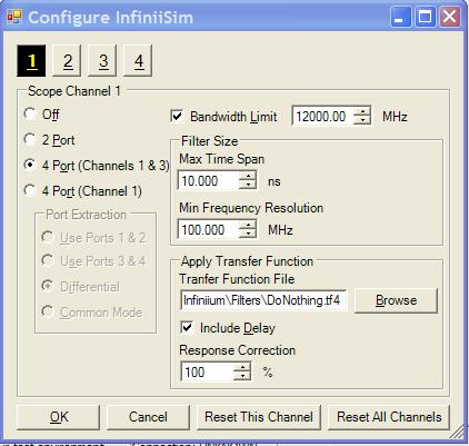
8 Agilent InfiniiSim Software (cont d) Select Save Transfer Function Click OK When the operation completes click OK When completed you will be returned to the InfiniiSim setup screen. Click Close. This will return you to the Channel Setup Screen. Click Close. Select Save Transfer Function When the transfer functions has finished being computed, click OK


9 Embedded Waveform Display CH1-3 is transformed with InfiniiSim into the embedded waveform (using hardware differential channels). Amplitude is slightly lower due to added loss. A saved waveform of the original waveform is shown for comparison After InfiniiSim is applied, you capture and save waveform files normally for post-processing with Sigtest. Original Signal Embedded Signal


10 Testing Transmitters with SigTest PCIe Validation for PC devices Motherboard Testing Select Embed losses Add-in Card Testing Select Embed losses Select System Test Template supporting embedded+ctle=dfe Select AIC Test Template supporting embedded+ctle=dfe

11 Agilent N5393C TX Test Application


12 N5393C TX Test Application Preset Tests De-emphasis Result for each Gen3 Preset Report Detail includes waveform captures useful for debug.


13 Tradition Method for De-Embedding Cable Losses Option 1: Six steps (you would need to do the following) Find a VNA Find a someone that knows how to use a VNA and measure the cable Create s- parameter file Save s-parameter file to USB drive and load on scope Learn waveform transformation software and correctly remove loss Analyze the data Option 2: Purchase the highest quality cables you can afford and accept those losses in your measurements.


14 PrecisionProbe characterizes and corrects in three easy steps 1. Measure Reference Plane 2. Measure loss of DUT cable 3. Save File Page 14

.")
15 Source Cable for PCIe 3.0 Low Loss PhaseMatched 3.5mm SMA compatible precision cables (1M). SMP/SMA Adapters (10cm)
16 Frequency Response of Each Cable Note point at which 10cm cable adds to overall losses Compensation produces ideal flat response to 16 GHz.
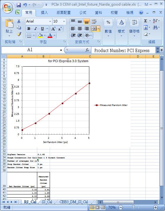
17 How much of a difference? 30.0% Add-in Card Precision Probe Eye Height and Jitter Differences 30.0% Root Complex Precision Probe Eye Height and Jitter Differences 25.0% 20.0% 20.0% 15.0% 10.0% 10.0% 5.0% Average eye height margin improvement of 16.6% 0.0% -10.0% Average reduction in jitter of 12.2% 0.0% -5.0% -20.0% -10.0% -30.0% -40.0% % Increase in eye Height % Increase in eye Height % Change in Jitter % Change in Jitter
!")
18 Frequency Response of Each Cable Raw Cables Precision Probe Cables Minimum Eye Height Improvement from mV to mV (20.2%)! Compensation produces ideal flat response to 16 GHz.
19 PCIe 3.0 Receiver Testing Preview (BASE/CEM)


20 Practical considerations of 8GT/s Signaling on RX Architecture Effective data rate shall be doubled Existing infrastructure of PCs and servers shall be reusable, which means: all PCIe2-compliant channels shall also be compliant with PCIe3 simulations showed: TX-de-emphasis not sufficient to achieve desired eye opening RX equalization is necessary 1. CTLE with seven different DC-attenuation settings peaking at 4 GHz 2. Reference CDR specified by OJTF with no peaking and 10MHz BW 3. One tap DFE 0 with a limit for 2-10 d1 of +/- 30mV Π-type reference -40 package model -50 also specified E+07 1E+08 1E+09 1E+10 1E E+04 1E+05 1E+06 1E+07 1E+08 1E+09 TP 6 4 CTLE -d 1 x DFE CDR TP 2-P Refclk Z -1 Decision Circuit y k y * Σ k x k lim amp FF V EYE, T EYE reference RX PCIe3RX stressed eye calibration Page 20 Oct 12 th 2010


21 Comparison of Calibration Methods Base vs CEM N4915A opt 014B Custom Test Board N4903B N4916B TP5 Replica Channel TP2 RX DUT ASIC SEASIM TP6 Breakout Channel Internal Loopback TX 81150A Base-Spec method utilizing Seasim : averaged step response, simulated pattern & impairments & ref RX Ref Clk input parameters: RJ = 2ps,rms SJ = 0.1UIpp DM-SI =14mVpp DM-SI N4916B J-BERT N4903B TP3 = TX-pad CBB rev. 3 SigTest SW w/ long cal channel CLB CEM method utilizing SigTest (for ref RX): CBB rev. 3 compliance pattern w/ impairments on w/o scope averaging TP6/TP2 = RX-pin TP2-P = RX behind EQ Page 21

 calibrate100mhz SJ to 12.5ps (0.")
 calibrate EH and EW for P7 after EQ of ref RX using SigTest varying DM-SI and RJ (compliance pattern) run tests")
 check BER <10-12 for DUT specific PG-EQ (for >3x10 12 bits Legend reconnection")
22 Calibration and Test Flow Chart de-embed test set-up start connect source (behind DC-block) to oscilloscope de-embed test-setup adjusting amplitude of clk/2 vs clk/128 calibrate BERT-PG equalization for all presets required during test (pre-) calibrate impairments before channel behind channel pre-calibrate RJ rms to 1.55ps (clk/2 pattern) calibrate100mhz SJ to 12.5ps (0.1 UI) (compliance pattern) insert channel (CBB riser -CBB main -CLB or CLB-CBB main pre-calibrate DM-SI to 20mV ( Pause -pattern) calibrate EH and EW for P7 after EQ of ref RX using SigTest varying DM-SI and RJ (compliance pattern) run tests connect BERT with DUT through CBB- CLB set DUT into Loopback and generate modified compliance pattern repetitively check BER <10-4 for P7 and P8 (for >10 5 bits) check BER <10-12 for DUT specific PG-EQ (for >3x10 12 bits Legend reconnection direct scope measurement measurement using SigTest pattern /signal generation w/ BERT test using BER measurement end Page 22

 (pre-) calibrate impairments bef ore channel behind channel insert channel (CBBriser-CBBmain-CLB or")


23 start de-embed test set-up connect source (behind DC-block) to scope de-embed test-set-up adjusting amplitude of clk/2 vs clk/128 calibrate BERT-PG equalization for all presets required during test pre-calibrate RJrms to 1.55ps calibrate100mhz SJ to 12.5ps (0.1 UI) (pre-) calibrate impairments bef ore channel behind channel insert channel (CBBriser-CBBmain-CLB or CLB-CBBmain pre-calibrate DM-SI to 20mV calibrate EH and EW for P7 after EQ of ref RX using SigTest varying DM-SI and RJ run tests connect BERT with DUT through CBB-CLB set DUT into Loopback and generate modified compliance pattern repetitively check BER <10-4 for P7 and P8 (for >10 5 bits) check BER <10-12 for DUT specific PG-EQ (for >3x10 12 bits end Set-Up for Calibration of RX Test Signal N4916B N4903B assymetrical splitters 2/14 db DM-SI 2/14 db DC-blocks 1 1 For Calibration before channel : cables 1 via SMP=>SMA adaptors to oscilloscope after channel: cables 1 to RX SMP connectors of CBB-riser card or CLB and cables 2 from TX SMP connectors of CLB or CBB-main card to oscilloscope CBB + CLB Agilent J-BERT N4903B with internal jitter generation and option J20 for 2.1GHz DM-SI generation N4916B de-emphasis signal converter DC-blocks and asymmetrical adders TP3 = TX-pad 2 numbering of test points according to base specification TP6 = RX-pin TP2-P = RX behind EQ Page 23

24 start de-embed test set-up connect source (behind DC-block) to scope de-embed test-set-up adjusting amplitude of clk/2 vs clk/128 calibrate BERT-PG equalization for all presets required during test pre-calibrate RJrms to 1.55ps calibrate100mhz SJ to 12.5ps (0.1 UI) (pre-) calibrate impairments bef ore channel behind channel insert channel (CBBriser-CBBmain-CLB or CLB-CBBmain pre-calibrate DM-SI to 20mV calibrate EH and EW for P7 after EQ of ref RX using SigTest varying DM-SI and RJ run tests connect BERT with DUT through CBB-CLB set DUT into Loopback and generate modified compliance pattern repetitively check BER <10-4 for P7 and P8 (for >10 5 bits) check BER <10-12 for DUT specific PG-EQ (for >3x10 12 bits end De-embedding of Test Set-up Cables, couplers, DC-blocks not ideal in frequency response Slightly lower a amplitude for clk/2 (HF signal) vs clk/128 signal (LF-signal) Correction of frequency response (same amplitude for HF and LF) per deemphasis post-cursor (Note: per definition: amplitude correction required) measured amplitude of HF signal ~ 750mV de-emphasis, Post-Cur1 = 0.0dB amplitude of BERT-PG, Vampt = 558 mv measured amplitude of HF signal ~ 800mV de-emphasis Post-Cur1 = dB amplitude of BERT-PG, Vampt = 604 mv a) b) Page 24
25 start de-embed test set-up connect source (behind DC-block) to scope de-embed test-set-up adjusting amplitude of clk/2 vs clk/128 calibrate BERT-PG equalization for all presets required during test pre-calibrate RJrms to 1.55ps calibrate100mhz SJ to 12.5ps (0.1 UI) (pre-) calibrate impairments bef ore channel behind channel insert channel (CBBriser-CBBmain-CLB or CLB-CBBmain pre-calibrate DM-SI to 20mV calibrate EH and EW for P7 after EQ of ref RX using SigTest varying DM-SI and RJ run tests connect BERT with DUT through CBB-CLB set DUT into Loopback and generate modified compliance pattern repetitively check BER <10-4 for P7 and P8 (for >10 5 bits) check BER <10-12 for DUT specific PG-EQ (for >3x10 12 bits end J-BERT GUI Data Output Page, De-embedding set-up of signal amplitude Vampt and de-emphasis Post-Curs1 Page 25

")
26 start de-embed test set-up connect source (behind DC-block) to scope de-embed test-set-up adjusting amplitude of clk/2 vs clk/128 calibrate BERT-PG equalization for all presets required during test pre-calibrate RJrms to 1.55ps calibrate100mhz SJ to 12.5ps (0.1 UI) (pre-) calibrate impairments bef ore channel behind channel insert channel (CBBriser-CBBmain-CLB or CLB-CBBmain pre-calibrate DM-SI to 20mV calibrate EH and EW for P7 after EQ of ref RX using SigTest varying DM-SI and RJ run tests connect BERT with DUT through CBB-CLB set DUT into Loopback and generate modified compliance pattern repetitively check BER <10-4 for P7 and P8 (for >10 5 bits) check BER <10-12 for DUT specific PG-EQ (for >3x10 12 bits end Possible TX EQ Settings and Presets Preset Number Preshoot De-emphasis Va/mV Vb/mV Vc/mV (db) Tol.: ±db (db) Tol.: Vd = 800 mv P P P P P P P P d m {-1,1} 1UI delay C -1 V TX P P UI delay C 0 C 1 V = V and = 1 TX PK c d c n m n n n= { 1,0,1} n= { 1,0,1} Page 26
27 start de-embed test set-up connect source (behind DC-block) to scope de-embed test-set-up adjusting amplitude of clk/2 vs clk/128 calibrate BERT-PG equalization for all presets required during test pre-calibrate RJrms to 1.55ps calibrate100mhz SJ to 12.5ps (0.1 UI) (pre-) calibrate impairments bef ore channel behind channel insert channel (CBBriser-CBBmain-CLB or CLB-CBBmain pre-calibrate DM-SI to 20mV calibrate EH and EW for P7 after EQ of ref RX using SigTest varying DM-SI and RJ run tests connect BERT with DUT through CBB-CLB set DUT into Loopback and generate modified compliance pattern repetitively check BER <10-4 for P7 and P8 (for >10 5 bits) check BER <10-12 for DUT specific PG-EQ (for >3x10 12 bits end BERT-PG Calibration for P7 with HF-LF-pattern a) 1xclk/128,128*clk/2 b) 1xclk/128,128*clk/2 V c V d V b V c V d V b V a [mv] V b [mv] V c [mv] V d [mv] V a c) V a Pre-shoot De-emphasis Boost measured [db] ideal [db] Page 27

28 start de-embed test set-up connect source (behind DC-block) to scope de-embed test-set-up adjusting amplitude of clk/2 vs clk/128 calibrate BERT-PG equalization for all presets required during test pre-calibrate RJrms to 1.55ps calibrate100mhz SJ to 12.5ps (0.1 UI) (pre-) calibrate impairments bef ore channel behind channel insert channel (CBBriser-CBBmain-CLB or CLB-CBBmain pre-calibrate DM-SI to 20mV calibrate EH and EW for P7 after EQ of ref RX using SigTest varying DM-SI and RJ run tests connect BERT with DUT through CBB-CLB set DUT into Loopback and generate modified compliance pattern repetitively check BER <10-4 for P7 and P8 (for >10 5 bits) check BER <10-12 for DUT specific PG-EQ (for >3x10 12 bits end J-BERT GUI Data Output Page, EQ-P7 set-up of signal amplitude Vampt, pre-shoot PreCur and de-emphasis Post-Curs1 Page 28
29 Target Values for Calibration Parameter Min Max Unit SigTest Technology Template Vpp 800 mv N/A N/A V RX-EH-8G Eye Height 50 mv PCI_3_0_CARD PCIE_3_8GB_MULTI_CTLE_DF E_80ps_50mV T RX-EH-8G Eye Width 0.36 (45) UI (ps) PCI_3_0_CARD PCIE_3_8GB_MULTI_CTLE_DF E_80ps_50mV Rj(Random Jitter) ps RMS PCI_3_0_RX_CAL PCIE_3_8GB_Rx_Sj_CAL Sj(Sinusoidal Jitter) 100 MHz ps PP PCI_3_0_RX_CAL PCIE_3_8GB_Rx_Sj_CAL Differential Mode Sinusoidal Interference at 2.1 GHz mv PP N/A N/A Page 29

30 start de-embed test set-up connect source (behind DC-block) to scope de-embed test-set-up adjusting amplitude of clk/2 vs clk/128 calibrate BERT-PG equalization for all presets required during test pre-calibrate RJrms to 1.55ps calibrate100mhz SJ to 12.5ps (0.1 UI) (pre-) calibrate impairments bef ore channel behind channel insert channel (CBBriser-CBBmain-CLB or CLB-CBBmain pre-calibrate DM-SI to 20mV calibrate EH and EW for P7 after EQ of ref RX using SigTest varying DM-SI and RJ run tests connect BERT with DUT through CBB-CLB set DUT into Loopback and generate modified compliance pattern repetitively check BER <10-4 for P7 and P8 (for >10 5 bits) check BER <10-12 for DUT specific PG-EQ (for >3x10 12 bits end J-BERT GUI Jitter Setup Page, Set-up of RJ set-up of RJamplitude (rms) and frequency range of 10-MHz-1GHz utilizing 10MHz high pass filter Page 30
31 start de-embed test set-up connect source (behind DC-block) to scope de-embed test-set-up adjusting amplitude of clk/2 vs clk/128 calibrate BERT-PG equalization for all presets required during test pre-calibrate RJrms to 1.55ps calibrate100mhz SJ to 12.5ps (0.1 UI) (pre-) calibrate impairments bef ore channel behind channel insert channel (CBBriser-CBBmain-CLB or CLB-CBBmain pre-calibrate DM-SI to 20mV calibrate EH and EW for P7 after EQ of ref RX using SigTest varying DM-SI and RJ run tests connect BERT with DUT through CBB-CLB set DUT into Loopback and generate modified compliance pattern repetitively check BER <10-4 for P7 and P8 (for >10 5 bits) check BER <10-12 for DUT specific PG-EQ (for >3x10 12 bits end SigTest SW Used for Calibration of Jitter Components,RJ For jitter decomposition and measurement the SEG provides the SigTest SW tool to rule out discrepancies arising from proprietary jitter separation algorithms implemented on the oscilloscopes of different vendors input panel result panel Page 31

32 start de-embed test set-up connect source (behind DC-block) to scope de-embed test-set-up adjusting amplitude of clk/2 vs clk/128 calibrate BERT-PG equalization for all presets required during test pre-calibrate RJrms to 1.55ps calibrate100mhz SJ to 12.5ps (0.1 UI) (pre-) calibrate impairments bef ore channel behind channel insert channel (CBBriser-CBBmain-CLB or CLB-CBBmain pre-calibrate DM-SI to 20mV calibrate EH and EW for P7 after EQ of ref RX using SigTest varying DM-SI and RJ run tests connect BERT with DUT through CBB-CLB set DUT into Loopback and generate modified compliance pattern repetitively check BER <10-4 for P7 and P8 (for >10 5 bits) check BER <10-12 for DUT specific PG-EQ (for >3x10 12 bits end SigTest SW Used for Calibration of Jitter Components,RJ For jitter decomposition and measurement the SEG provides the SigTest SW tool to rule out discrepancies arising from proprietary jitter separation algorithms implemented on the oscilloscopes of different vendors input panel result panel Page 32

 (pre-) calibrate impairments bef ore channel behind channel insert channel (CBBriser-CBBmain-CLB or")

")
33 start de-embed test set-up connect source (behind DC-block) to scope de-embed test-set-up adjusting amplitude of clk/2 vs clk/128 calibrate BERT-PG equalization for all presets required during test pre-calibrate RJrms to 1.55ps calibrate100mhz SJ to 12.5ps (0.1 UI) (pre-) calibrate impairments bef ore channel behind channel insert channel (CBBriser-CBBmain-CLB or CLB-CBBmain pre-calibrate DM-SI to 20mV calibrate EH and EW for P7 after EQ of ref RX using SigTest varying DM-SI and RJ run tests connect BERT with DUT through CBB-CLB set DUT into Loopback and generate modified compliance pattern repetitively check BER <10-4 for P7 and P8 (for >10 5 bits) check BER <10-12 for DUT specific PG-EQ (for >3x10 12 bits end PJ2 Background Sweep and Jitter Tolerance Compliance Measurement jitter set-up page showing PJ2 a) jitter tolerance compliance measurement reporting BER pass-fail result for every step b) b) d) pass fail c) Page 33
34 start de-embed test set-up connect source (behind DC-block) to scope de-embed test-set-up adjusting amplitude of clk/2 vs clk/128 calibrate BERT-PG equalization for all presets required during test pre-calibrate RJrms to 1.55ps calibrate100mhz SJ to 12.5ps (0.1 UI) (pre-) calibrate impairments bef ore channel behind channel insert channel (CBBriser-CBBmain-CLB or CLB-CBBmain pre-calibrate DM-SI to 20mV calibrate EH and EW for P7 after EQ of ref RX using SigTest varying DM-SI and RJ run tests connect BERT with DUT through CBB-CLB set DUT into Loopback and generate modified compliance pattern repetitively check BER <10-4 for P7 and P8 (for >10 5 bits) check BER <10-12 for DUT specific PG-EQ (for >3x10 12 bits end SigTest SW Used for Calibration of Jitter Components, SJ At first the intrinsic jitter (for PJ=0) is measured for reference in this case (not shown) TJ 0 = 12.4 ps was determined increase PJ until max pp-jitter ranges from 24.9 to 26.9 ps input panel result panel Page 34

35 start de-embed test set-up connect source (behind DC-block) to scope de-embed test-set-up adjusting amplitude of clk/2 vs clk/128 calibrate BERT-PG equalization for all presets required during test pre-calibrate RJrms to 1.55ps calibrate100mhz SJ to 12.5ps (0.1 UI) (pre-) calibrate impairments bef ore channel behind channel insert channel (CBBriser-CBBmain-CLB or CLB-CBBmain pre-calibrate DM-SI to 20mV calibrate EH and EW for P7 after EQ of ref RX using SigTest varying DM-SI and RJ run tests connect BERT with DUT through CBB-CLB set DUT into Loopback and generate modified compliance pattern repetitively check BER <10-4 for P7 and P8 (for >10 5 bits) check BER <10-12 for DUT specific PG-EQ (for >3x10 12 bits end SigTest SW Used for Calibration of Jitter Components, SJ At first the intrinsic jitter (for PJ=0) is measured for reference in this case (not shown) TJ 0 = 12.4 ps was determined increase PJ until max pp-jitter ranges from 24.9 to 26.9 ps input panel result panel Page 35

")
36 start de-embed test set-up connect source (behind DC-block) to scope de-embed test-set-up adjusting amplitude of clk/2 vs clk/128 calibrate BERT-PG equalization for all presets required during test pre-calibrate RJrms to 1.55ps calibrate100mhz SJ to 12.5ps (0.1 UI) (pre-) calibrate impairments bef ore channel behind channel insert channel (CBBriser-CBBmain-CLB or CLB-CBBmain pre-calibrate DM-SI to 20mV calibrate EH and EW for P7 after EQ of ref RX using SigTest varying DM-SI and RJ run tests connect BERT with DUT through CBB-CLB set DUT into Loopback and generate modified compliance pattern repetitively check BER <10-4 for P7 and P8 (for >10 5 bits) check BER <10-12 for DUT specific PG-EQ (for >3x10 12 bits end Differential Mode Sinusoidal Interference (DM-SI) A) B) BERT-PG generates a Pause -pattern (with 0mV amplitude) J-BERT Interfernce Channel is set to generate a 2.1GHz differential mode sinusoid DM-SI is calibrated behind the channel (Vp-p measurement) Page 36
37 start de-embed test set-up connect source (behind DC-block) to scope de-embed test-set-up adjusting amplitude of clk/2 vs clk/128 calibrate BERT-PG equalization for all presets required during test pre-calibrate RJrms to 1.55ps calibrate100mhz SJ to 12.5ps (0.1 UI) (pre-) calibrate impairments bef ore channel behind channel insert channel (CBBriser-CBBmain-CLB or CLB-CBBmain pre-calibrate DM-SI to 20mV calibrate EH and EW for P7 after EQ of ref RX using SigTest varying DM-SI and RJ run tests connect BERT with DUT through CBB-CLB set DUT into Loopback and generate modified compliance pattern repetitively check BER <10-4 for P7 and P8 (for >10 5 bits) check BER <10-12 for DUT specific PG-EQ (for >3x10 12 bits end Final Adjust Procedure for EH and EW Set up J-BERT to generate compliance pattern with P7 activated Each of the following steps consists of a sequence of: 1. set the parameter on J-BERT 2. capture the waveform on the oscilloscope 3. load waveform into SigTest 4. determine eye opening parameters using SigTest Adjust DM-SI to meet specified EH Adjust RJ to meet specified EW Re-check EH and if necessary re-adjust DM-SI once Record the final calibration values RJ cal and DM-SI cal for later usage Page 37

38 start de-embed test set-up connect source (behind DC-block) to scope de-embed test-set-up adjusting amplitude of clk/2 vs clk/128 calibrate BERT-PG equalization for all presets required during test pre-calibrate RJrms to 1.55ps calibrate100mhz SJ to 12.5ps (0.1 UI) (pre-) calibrate impairments bef ore channel behind channel insert channel (CBBriser-CBBmain-CLB or CLB-CBBmain pre-calibrate DM-SI to 20mV calibrate EH and EW for P7 after EQ of ref RX using SigTest varying DM-SI and RJ run tests connect BERT with DUT through CBB-CLB set DUT into Loopback and generate modified compliance pattern repetitively check BER <10-4 for P7 and P8 (for >10 5 bits) check BER <10-12 for DUT specific PG-EQ (for >3x10 12 bits end SigTest SW Used for Calibration of Stressed Eye, EH and EW Waveform (compliance pattern) with all impairments on is captured Different technology and template is chosen DM-SI and RJ varied until target values EH=50mV and EW=45ps achieved input panel result panel Page 38
39 start de-embed test set-up connect source (behind DC-block) to scope de-embed test-set-up adjusting amplitude of clk/2 vs clk/128 calibrate BERT-PG equalization for all presets required during test pre-calibrate RJrms to 1.55ps calibrate100mhz SJ to 12.5ps (0.1 UI) (pre-) calibrate impairments bef ore channel behind channel insert channel (CBBriser-CBBmain-CLB or CLB-CBBmain pre-calibrate DM-SI to 20mV calibrate EH and EW for P7 after EQ of ref RX using SigTest varying DM-SI and RJ run tests connect BERT with DUT through CBB-CLB set DUT into Loopback and generate modified compliance pattern repetitively check BER <10-4 for P7 and P8 (for >10 5 bits) check BER <10-12 for DUT specific PG-EQ (for >3x10 12 bits end Typical Values on J-BERT Achieving a Calibrated Stress Signal de-embed P8 P7 Vampt / mv Pre-Curs / db Post-Cur1 / db pre-adjust final adjust (EW/ EH) RJ / mui (ps) RMS 11.5 (1.44) 11.5 (1.44) PJ2 / mui (ps) 110 (13.8) 110 (13.8) DM-SI /mv actual values may differ because they depend on parameters of individual units in use, as well instrumentation, accessories or SIG-boards Page 39
40 N5990 Automation SW Page 40
41 start de-embed test set-up connect source (behind DC-block) to scope de-embed test-set-up adjusting amplitude of clk/2 vs clk/128 calibrate BERT-PG equalization for all presets required during test pre-calibrate RJrms to 1.55ps calibrate100mhz SJ to 12.5ps (0.1 UI) (pre-) calibrate impairments bef ore channel behind channel insert channel (CBBriser-CBBmain-CLB or CLB-CBBmain pre-calibrate DM-SI to 20mV calibrate EH and EW for P7 after EQ of ref RX using SigTest varying DM-SI and RJ run tests connect BERT with DUT through CBB-CLB set DUT into Loopback and generate modified compliance pattern repetitively check BER <10-4 for P7 and P8 (for >10 5 bits) check BER <10-12 for DUT specific PG-EQ (for >3x10 12 bits end Set-Up for Mother Boards (Calibration) According to CEM Specification Rev. 3.0 J-BERT N4903B N4916B RX-in 2.1GHz diff. mode sinusoidal asymmetrical splitter PSPL dB DC-block N9398C Interference CLB to Real Time Scope for calibration Final calibration performed with PCIe3 compliance pattern and all impairments turned on SigTest SW calculates EW and EH CBB rev. 3 Page 41

")
42 start de-embed test set-up connect source (behind DC-block) to scope de-embed test-set-up adjusting amplitude of clk/2 vs clk/128 calibrate BERT-PG equalization for all presets required during test pre-calibrate RJrms to 1.55ps calibrate100mhz SJ to 12.5ps (0.1 UI) (pre-) calibrate impairments bef ore channel behind channel insert channel (CBBriser-CBBmain-CLB or CLB-CBBmain pre-calibrate DM-SI to 20mV calibrate EH and EW for P7 after EQ of ref RX using SigTest varying DM-SI and RJ run tests connect BERT with DUT through CBB-CLB set DUT into Loopback and generate modified compliance pattern repetitively check BER <10-4 for P7 and P8 (for >10 5 bits) check BER <10-12 for DUT specific PG-EQ (for >3x10 12 bits end Set-Up for Mother Boards (Test) According to CEM Specification Rev. 3.0 J-BERT N4903B N4916B RX-in 2.1GHz diff. mode sinusoidal asymmetrical splitter PSPL dB DC-block N9398C Interference CLB ASIC 8GHz Repeater TX-out ref clk out N4880A BERT generator runs on mother board ref clock 100 MHz Mother Board N4880A Reference Clock Multiplying operates according to PCIe specs Page 42

 (pre-) calibrate impairments bef ore channel behind channel insert channel (CBBriser-CBBmain-CLB or")


, TS1 advertising that all speeds from 2.")
43 start de-embed test set-up connect source (behind DC-block) to scope de-embed test-set-up adjusting amplitude of clk/2 vs clk/128 calibrate BERT-PG equalization for all presets required during test pre-calibrate RJrms to 1.55ps calibrate100mhz SJ to 12.5ps (0.1 UI) (pre-) calibrate impairments bef ore channel behind channel insert channel (CBBriser-CBBmain-CLB or CLB-CBBmain pre-calibrate DM-SI to 20mV calibrate EH and EW for P7 after EQ of ref RX using SigTest varying DM-SI and RJ run tests connect BERT with DUT through CBB-CLB set DUT into Loopback and generate modified compliance pattern repetitively check BER <10-4 for P7 and P8 (for >10 5 bits) check BER <10-12 for DUT specific PG-EQ (for >3x10 12 bits end How to Set the DUT into Loopback Fig 4-21: Link Training and Status State Machine Same procedure as for PCIe 1 and 2 until speed adjustment only that 8GT/s is advertised Loopback entry not yet defined in rev.3 Test Spec (EIEOS), TS1 advertising that all speeds from 2.5GT/s to 8GT/s are supported; Loopback bit set to 1b, Equalization Control set to 0b, Transmitter preset communicated 2.5GT/s 8GT/s Page 43
44 Conclusions 1. De-embedding Cables alone can increase eye height up to 20%. 2. RX Calibration is the biggest challenge of PCIe 3.0 Testing 3. PCIe 3.0 Presets can yield open eyes in the presence of a PCIe 3.0 Compliant Channel, especially after only CTLE equalization 4. Calibration of the stressed eye for receiver test should minimize effect of instrument noise. BASE Spec since it must be calibrated to 10E-12 BER. 5. AIC TX Testing must convolve reference Channel in addition to Reference Package model losses.
Receiver Testing to Third Generation Standards. Jim Dunford, October 2011
 Receiver Testing to Third Generation Standards Jim Dunford, October 2011 Agenda 1.Introduction 2. Stressed Eye 3. System Aspects 4. Beyond Compliance 5. Resources 6. Receiver Test Demonstration PCI Express
High-Speed Digital Interface 4.0 (PCIe, SAS) Insight and Test Solutions. Francis Liu Senior Project Manager Keysight Technologies
 Insight and Test Solutions. Francis Liu Senior Project Manager Keysight Technologies") High-Speed Digital Interface 4.0 (PCIe, SAS) Insight and Test Solutions Francis Liu Senior Project Manager Keysight Technologies Page 1 Agenda PCIe 4.0 Ecosystem and Timeline PCIe 4.0 TX Testing and Tools
High-Speed Digital Interface 4.0 (PCIe, SAS) Insight and Test Solutions Francis Liu Senior Project Manager Keysight Technologies Page 1 Agenda PCIe 4.0 Ecosystem and Timeline PCIe 4.0 TX Testing and Tools
Combating Closed Eyes Design & Measurement of Pre-Emphasis and Equalization for Lossy Channels
 Combating Closed Eyes Design & Measurement of Pre-Emphasis and Equalization for Lossy Channels Why Test the Receiver? Serial Data communications standards have always specified both the transmitter and
Combating Closed Eyes Design & Measurement of Pre-Emphasis and Equalization for Lossy Channels
 Combating Closed Eyes Design & Measurement of Pre-Emphasis and Equalization for Lossy Channels Why Test the Receiver? Serial Data communications standards have always specified both the transmitter and
Emphasis, Equalization & Embedding
 Emphasis, Equalization & Embedding Cleaning the Rusty Channel Gustaaf Sutorius Application Engineer Agilent Technologies gustaaf_sutorius@agilent.com Dr. Thomas Kirchner Senior Application Engineer Digital
Validation of VSR Module to Host link
 Validation of VSR Module to Host link Your Imagination, Our Innovation Work done for OIF and presented in OIF2013.170.4 to close comment on VSR draft 9. 1 Problem Statement Much work has been done to ensure
Prepare for Next Generation USB Technology Testing
 Prepare for Next Generation USB Technology Testing Disclaimer The USB 3.1 compliance test requirements are not final therefore all opinions, judgments, recommendations, etc., that are presented herein
100G EDR and QSFP+ Cable Test Solutions
 100G EDR and QSFP+ Cable Test Solutions (IBTA, 100GbE, CEI) DesignCon 2017 James Morgante Anritsu Company Presenter Bio James Morgante Application Engineer Eastern United States james.morgante@anritsu.com
Practical De-embedding for Gigabit fixture. Ben Chia Senior Signal Integrity Consultant 5/17/2011
 Practical De-embedding for Gigabit fixture Ben Chia Senior Signal Integrity Consultant 5/17/2011 Topics Why De-Embedding/Embedding? De-embedding in Time Domain De-embedding in Frequency Domain De-embedding
PAM4 signals for 400 Gbps: acquisition for measurement and signal processing
 TITLE PAM4 signals for 400 Gbps: acquisition for measurement and signal processing Image V1.00 1 Introduction, content High speed serial data links are in the process in increasing line speeds from 25
USB 3.1 ENGINEERING CHANGE NOTICE
 Title: SSP System Jitter Budget Applied to: USB_3_1r1.0_07_31_2013 Brief description of the functional changes: Change to the 10Gbps system jitter budget. The change reduces the random jitter (RJ) budget
Why Engineers Ignore Cable Loss
 Why Engineers Ignore Cable Loss By Brig Asay, Agilent Technologies Companies spend large amounts of money on test and measurement equipment. One of the largest purchases for high speed designers is a real
Next Generation Ultra-High speed standards measurements of Optical and Electrical signals
 Next Generation Ultra-High speed standards measurements of Optical and Electrical signals Apr. 2011, V 1.0, prz Agenda Speeds above 10 Gb/s: Transmitter and Receiver test setup Transmitter Test 1,2 : Interconnect,
Draft Baseline Proposal for CDAUI-8 Chipto-Module (C2M) Electrical Interface (NRZ)
 Electrical Interface (NRZ)") Draft Baseline Proposal for CDAUI-8 Chipto-Module (C2M) Electrical Interface (NRZ) Authors: Tom Palkert: MoSys Jeff Trombley, Haoli Qian: Credo Date: Dec. 4 2014 Presented: IEEE 802.3bs electrical interface
Draft Baseline Proposal for CDAUI-8 Chipto-Module (C2M) Electrical Interface (NRZ) Authors: Tom Palkert: MoSys Jeff Trombley, Haoli Qian: Credo Date: Dec. 4 2014 Presented: IEEE 802.3bs electrical interface
32 G/64 Gbaud Multi Channel PAM4 BERT
 Product Introduction 32 G/64 Gbaud Multi Channel PAM4 BERT PAM4 PPG MU196020A PAM4 ED MU196040A Signal Quality Analyzer-R MP1900A Series Outline of MP1900A series PAM4 BERT Supports bit error rate measurements
InfiniBand Trade Association
 InfiniBand Trade Association Revision 1.02 3/30/2014 IBTA Receiver MOI for FDR Devices For Anritsu MP1800A Signal Analyzer and Agilent 86100D with module 86108B and FlexDCA S/W for stressed signal calibration
New Serial Link Simulation Process, 6 Gbps SAS Case Study
 ew Serial Link Simulation Process, 6 Gbps SAS Case Study Donald Telian SI Consultant Session 7-TH2 Donald Telian SI Consultant About the Authors Donald Telian is an independent Signal Integrity Consultant.
USB3.1 / Type-C / Power Delivery Test Challenge and Solution
 Woo Jun-Hyung / Choi Seok-Keun USB3.1 / Type-C / Power Delivery Test Challenge and Solution Page USB Type C Connector and USB3.1 Test Solution Agenda Page 3 Introduction to the USB Type C Connector USB3.1
Next Generation 인터페이스테크놀로지트렌드
 Next Generation 인터페이스테크놀로지트렌드 (USB3.1, HDMI2.0, MHL3.2) 텍트로닉스박영준부장 Agenda USB3.1 Compliance Test update What s different for USB3.1 Transmitter and Receiver Compliance Test HDMI2.0, MHL3.2 overview Q &
InfiniBand Trade Association
 InfiniBand Trade Association Revision 1.04 2/27/2014 IBTA Receiver MOI for FDR Devices For Tektronix BERTScope Bit Error Rate Tester and Agilent 86100D with module 86108B and FlexDCA S/W for stressed signal
Tektronix Inc. DisplayPort Standard
 DisplayPort Standard 06-12-2008 DisplayPort Standard Tektronix MOI for Sink Tests (AWG Jitter Generation using Direct Synthesis and calibration using Real Time DPO measurements for Sink Devices) DisplayPort
PCIe: EYE DIAGRAM ANALYSIS IN HYPERLYNX
 PCIe: EYE DIAGRAM ANALYSIS IN HYPERLYNX w w w. m e n t o r. c o m PCIe: Eye Diagram Analysis in HyperLynx PCI Express Tutorial This PCI Express tutorial will walk you through time-domain eye diagram analysis
M809256PA OIF-CEI CEI-56G Pre-Compliance Receiver Test Application
 M809256PA OIF-CEI CEI-56G Pre-Compliance Receiver Test Application Find us at www.keysight.com Page 1 Table of Contents Key Features... 3 Description... 3 Calibrations and Tests Covered by M809256PA Pre-Compliance
100G SR4 Link Model Update & TDP. John Petrilla: Avago Technologies January 2013
 100G SR4 Link Model Update & TDP John Petrilla: Avago Technologies January 2013 100G 100m Transceivers Summary Presentation Objectives: Provide an update of the example link model for 100G 100m MMF Discuss
Manual Supplement. This supplement contains information necessary to ensure the accuracy of the above manual.
 Manual Title: 9500B Users Supplement Issue: 2 Part Number: 1625019 Issue Date: 9/06 Print Date: October 2005 Page Count: 6 Version 11 This supplement contains information necessary to ensure the accuracy
GT Dual-Row Nano Vertical SMT High Speed Characterization Report For Differential Data Applications
 GT-16-95 Dual-Row Nano Vertical SMT For Differential Data Applications 891-011-15S Vertical SMT PCB 891-001-15P Cable Mount Revision History Rev Date Approved Description A 6/3/2016 R. Ghiselli/D. Armani
SV1C Personalized SerDes Tester. Data Sheet
 SV1C Personalized SerDes Tester Data Sheet Table of Contents 1 Table of Contents Table of Contents Table of Contents... 2 List of Figures... 3 List of Tables... 3 Introduction... 4 Overview... 4 Key Benefits...
GT Dual-Row Nano Vertical Thru-Hole High Speed Characterization Report For Differential Data Applications
 GT-16-97 Dual-Row Nano Vertical Thru-Hole For Differential Data Applications 891-007-15S Vertical Thru-Hole PCB 891-001-15P Cable Mount Revision History Rev Date Approved Description A 8/31/2016 R. Ghiselli/G.
Agilent MOI for HDMI 1.4b Cable Assembly Test Revision Jul 2012
 Revision 1.11 19-Jul 2012 Agilent Method of Implementation (MOI) for HDMI 1.4b Cable Assembly Test Using Agilent E5071C ENA Network Analyzer Option TDR 1 Table of Contents 1. Modification Record... 4 2.
立肯科技 LeColn Technology
 DisplayPort PHY Validation 立肯科技 LeColn Technology 1 DisplayPort Basics Maximum bit rate DP1.2b 1.62Gb/s( RBR = reduced bit rate) 2.7Gb/s( HBR = high bit rate) 5.4Gb/s( HBR2 =high bit rate 2) DP1.3/1.4
Switching Solutions for Multi-Channel High Speed Serial Port Testing
 Switching Solutions for Multi-Channel High Speed Serial Port Testing Application Note by Robert Waldeck VP Business Development, ASCOR Switching The instruments used in High Speed Serial Port testing are
Agilent E4887A HDMI TMDS Signal Generator Platform
 Agilent E4887A HDMI TMDS Signal Generator Platform Data Sheet Version 1.9 Preliminary E4887A- 007 E4887A- 037 E4887A- 003 Page Convenient Compliance Testing and Characterization of HDMI 1.3 Devices The
Comparison of NRZ, PR-2, and PR-4 signaling. Qasim Chaudry Adam Healey Greg Sheets
 Comparison of NRZ, PR-2, and PR-4 signaling Presented by: Rob Brink Contributors: Pervez Aziz Qasim Chaudry Adam Healey Greg Sheets Scope and Purpose Operation over electrical backplanes at 10.3125Gb/s
BRR Tektronix BroadR-Reach Compliance Solution for Automotive Ethernet. Anshuman Bhat Product Manager
 BRR Tektronix BroadR-Reach Compliance Solution for Automotive Ethernet Anshuman Bhat Product Manager anshuman.bhat@tektronix.com Agenda BroadR-Reach Automotive Market Technology Overview Open Alliance
Ali Ghiasi. Nov 8, 2011 IEEE GNGOPTX Study Group Atlanta
 Ali Ghiasi Nov 8, 2011 IEEE 802.3 100GNGOPTX Study Group Atlanta 1 Overview I/O Trend Line card implementations VSR/CAUI-4 application model cppi-4 application model VSR loss budget Possible CAUI-4 loss
100GBASE-SR4 Extinction Ratio Requirement. John Petrilla: Avago Technologies September 2013
 100GBASE-SR4 Extinction Ratio Requirement John Petrilla: Avago Technologies September 2013 Presentation Summary Eye displays for the worst case TP1 and Tx conditions that were used to define Clause 95
SV1C Personalized SerDes Tester
 SV1C Personalized SerDes Tester Data Sheet SV1C Personalized SerDes Tester Data Sheet Revision: 1.0 2013-02-27 Revision Revision History Date 1.0 Document release Feb 27, 2013 The information in this
Electrical and Optical Clock Data Recovery Solutions up to 32 Gb/s
 Agilent N4877A Clock Data Recovery and Demultiplexer 1:2 Agilent N1075A Optical Pick-Off/Converter Agilent N1070A Optical Clock Recovery Solution Version 1.0 Data Sheet Figure 1. N1070A optical clock data
Agilent N4876A 28 Gb/s Multiplexer 2:1
 Agilent N4876A 28 Gb/s Multiplexer 2:1 Data Sheet Revision 1.0 Features and Benefits Variable data rate up to 28.4 Gb/s Multiplexes two generator channels Front-end box for J-BERT or ParBERT Control via
Keysight Method of Implementation (MOI) for VESA DisplayPort (DP) Standard Version 1.3 Cable-Connector Compliance Tests Using E5071C ENA Option TDR
 for VESA DisplayPort (DP) Standard Version 1.3 Cable-Connector Compliance Tests Using E5071C ENA Option TDR") Revision 1.00 February 27, 2015 Keysight Method of Implementation (MOI) for VESA DisplayPort (DP) Standard Version 1.3 Cable-Connector Compliance Tests Using E5071C ENA Option TDR 1 Table of Contents 1.
Revision 1.00 February 27, 2015 Keysight Method of Implementation (MOI) for VESA DisplayPort (DP) Standard Version 1.3 Cable-Connector Compliance Tests Using E5071C ENA Option TDR 1 Table of Contents 1.
Draft 100G SR4 TxVEC - TDP Update. John Petrilla: Avago Technologies February 2014
 Draft 100G SR4 TxVEC - TDP Update John Petrilla: Avago Technologies February 2014 Supporters David Cunningham Jonathan King Patrick Decker Avago Technologies Finisar Oracle MMF ad hoc February 2014 Avago
N4917BACA Optical Receiver Stress Test Solution 100 Gb/s Ethernet
 N4917BACA Optical Receiver Stress Test Solution 100 Gb/s Ethernet 25GBASE-LR/-ER/-SR, 100BASE-LR4/-ER4/-SR4 and MSAs Complete optical receiver stress test solution for 100GbE optical transceivers with
Agilent N6467A BroadR-Reach Compliance Test Application. Methods of Implementation
 Agilent N6467A BroadR-Reach Compliance Test Application Methods of Implementation s1 Notices Agilent Technologies, Inc. 2013 No part of this manual may be reproduced in any form or by any means (including
Agilent N4965A Multi-Channel BERT 12.5 Gb/s Data Sheet
 Agilent Multi-Channel BERT 2.5 Gb/s Data Sheet Highly cost effective solution for characterizing crosstalk susceptibility, backplanes and multi-lane serial data systems Product highlights Modular architecture
Agilent Technologies Pulse Pattern and Data Generators Digital Stimulus Solutions
 Agilent Technologies Pattern and Data Generators Digital Stimulus Solutions Leading pulse, pattern, data and clock generation for all test needs in digital design and manufacturing Pattern Generators Agilent
Electrical Sampling Modules Datasheet 80E11 80E11X1 80E10B 80E09B 80E08B 80E07B 80E04 80E03 80E03-NV
 Electrical Sampling Modules Datasheet 80E11 80E11X1 80E10B 80E09B 80E08B 80E07B 80E04 80E03 80E03-NV The DSA8300 Series Sampling Oscilloscope, when configured with one or more electrical sampling modules,
DisplayPort TX & RX Testing Solutions
 DisplayPort TX & RX Testing Solutions Agenda DP Technology Overview DPC TX Solution DPC RX Solution 2 DP Technology Overview 3 DisplayPort Standards Standards DP 1.2 May, 2012 DP over Type-C Spec Aug,
Datasheet SHF A
 SHF Communication Technologies AG Wilhelm-von-Siemens-Str. 23D 12277 Berlin Germany Phone +49 30 772051-0 Fax ++49 30 7531078 E-Mail: sales@shf.de Web: http://www.shf.de Datasheet SHF 19120 A 2.85 GSa/s
Senior Project Manager / AEO
 Kenny Liao 2018.12.18&20 Senior Project Manager / AEO Measurement Demo Prepare instrument for measurement Calibration Fixture removal Conclusion What next? Future trends Resources Acquire channel data
Keysight N1085A PAM-4 Measurement Application For 86100D DCA-X Series Oscilloscopes. Data Sheet
 Keysight N1085A PAM-4 Measurement Application For 86100D DCA-X Series Oscilloscopes Data Sheet Introduction Several industry groups and standards bodies are using, or actively considering using, Pulse
ASNT_PRBS20B_1 18Gbps PRBS7/15 Generator Featuring Jitter Insertion, Selectable Sync, and Output Amplitude Control
 ASNT_PRBS20B_1 18Gbps PRBS7/15 Generator Featuring Jitter Insertion, Selectable Sync, and Output Amplitude Control Broadband frequency range from 20Mbps 18.0Gbps Minimal insertion jitter Fast rise and
Keysight N4965A Multi-Channel BERT 12.5 Gb/s. Data Sheet
 Keysight Multi-Channel BERT 2.5 Gb/s Data Sheet 02 Keysight Multi-Channel BERT 2.5 Gb/s - Data Sheet Highly cost effective solution for characterizing crosstalk susceptibility, backplanes and multi-lane
SECQ Test Method and Calibration Improvements
 SECQ Test Method and Calibration Improvements IEEE802.3cd, Geneva, January 22, 2018 Matt Sysak, Adee Ran, Hai-Feng Liu, Scott Schube In support of comments 82-84 Summary We are proposing revising the wording
CDAUI-8 Chip-to-Module (C2M) System Analysis #3. Ben Smith and Stephane Dallaire, Inphi Corporation IEEE 802.3bs, Bonita Springs, September 2015
 System Analysis #3. Ben Smith and Stephane Dallaire, Inphi Corporation IEEE 802.3bs, Bonita Springs, September 2015") CDAUI-8 Chip-to-Module (C2M) System Analysis #3 Ben Smith and Stephane Dallaire, Inphi Corporation IEEE 802.3bs, Bonita Springs, September 2015 Supporters Ali Ghiasi, Ghiasi Quantum LLC Marco Mazzini,
CDAUI-8 Chip-to-Module (C2M) System Analysis #3 Ben Smith and Stephane Dallaire, Inphi Corporation IEEE 802.3bs, Bonita Springs, September 2015 Supporters Ali Ghiasi, Ghiasi Quantum LLC Marco Mazzini,
Agilent N4876A 28 Gb/s Multiplexer 2:1
 Agilent N4876A 28 Gb/s Multiplexer 2:1 Data Sheet, Revision 1.1 Features and Benefits Variable data rate up to 28.4 Gb/s Multiplexes two generator channels Front-end box for J-BERT or ParBERT Control via
Keysight Technologies M8048A ISI Channels
 Keysight Technologies M8048A ISI Channels Master Your Next Designs Data Sheet Key features Emulate a wide range of channel loss with cascadable ISI traces with fine resolution 4 short (7.7 to 12.8 ) and
Agilent N5431A XAUI Electrical Validation Application
 Agilent N5431A XAUI Electrical Validation Application Methods of Implementation s Agilent Technologies Notices Agilent Technologies, Inc. 2008 No part of this manual may be reproduced in any form or by
Using Allegro PCB SI GXL to Make Your Multi-GHz Serial Link Work Right Out of the Box
 Using Allegro PCB SI GXL to Make Your Multi-GHz Serial Link Work Right Out of the Box Session 8.11 - Hamid Kharrati - A2e Technologies Agenda About the Project Modeling the System Frequency Domain Analysis
Eye Doctor II Advanced Signal Integrity Tools
 Eye Doctor II Advanced Signal Integrity Tools EYE DOCTOR II ADVANCED SIGNAL INTEGRITY TOOLS Key Features Eye Doctor II provides the channel emulation and de-embedding tools Adds precision to signal integrity
Serial ATA International Organization
 Serial ATA International Organization Version 1.00 24-October 2007 Serial ATA Interoperability Program Revision 1.2 Agilent MOI for SATA RSG Tests This document is provided "AS IS" and without any warranty
QPHY-USB3 USB3.0 Serial Data Operator s Manual
 QPHY-USB3 USB3.0 Serial Data Operator s Manual Revision A April, 2009 Relating to the Following Release Versions: Software Option Rev. 5.8 USB3 Script Rev. 1.0 Style Sheet Rev. 1.2 LeCroy Corporation 700
SDAIII-CompleteLinQ Multi-Lane Serial Data, Noise and Crosstalk Analysis
 SDAIII-CompleteLinQ Multi-Lane Serial Data, Noise and Crosstalk Analysis TOOLS TO MEET SERIAL DATA ANALYSIS CHALLENGES Key Features Most complete jitter decomposition, eye diagram and analysis tools Up
SDLA Visualizer Serial Data Link Analysis Visualizer Software Printable Application Help
 SDLA Visualizer Serial Data Link Analysis Visualizer Software Printable Application Help *P076017306* 076-0173-06 SDLA Visualizer Serial Data Link Analysis Visualizer Software Printable Application Help
Keysight Technologies N4917A Optical Receiver Stress Test Solution. Data Sheet Version 1.3 New: Extension to 8G Fibre Channel
 Keysight Technologies N4917A Optical Receiver Stress Test Solution Data Sheet Version 1.3 New: Extension to 8G Fibre Channel 2 Keysight M9037A PXIe Embedded Controller - Data Sheet Repeatable optical receiver
ELECTRICAL PERFORMANCE REPORT
 CIRCUITS & DESIGN ELECTRICAL PERFORMANCE REPORT DENSIPAC 4 ROW Date: 06-12-2006 Circuits & Design EMEA Circuits & Design 1/21 06/12/2006 1 INTRODUCTION... 3 2 CONNECTORS, TEST BOARDS AND TEST EQUIPMENT...
The Challenges of Measuring PAM4 Signals
 TITLE The Challenges of Measuring PAM4 Signals Panelists: Doug Burns, SiSoft Stephen Mueller, Teledyne LeCroy Luis Boluña, Keysight Technologies Mark Guenther, Tektronix Image Jose Moreira, Advantest Martin
LOW POWER DIGITAL EQUALIZATION FOR HIGH SPEED SERDES. Masum Hossain University of Alberta
 LOW POWER DIGITAL EQUALIZATION FOR HIGH SPEED SERDES Masum Hossain University of Alberta 0 Outline Why ADC-Based receiver? Challenges in ADC-based receiver ADC-DSP based Receiver Reducing impact of Quantization
SignalCorrect Software and TCS70902 Calibration Source Option SC SignalCorrect software
 SignalCorrect Software and TCS70902 Calibration Source Option SC SignalCorrect software Eye of signal after de-embed using SignalCorrect Features and benefits Measurement and de-embed: Characterize cables
2016 PDV Conference. Time Alignment of Multiple Real-Time High Bandwidth Scope. Channels
 Time Alignment of Multiple Real-Time High Bandwidth Scope Channels 1 Time Synchronization Between Scope Channels for Data Acquisition Large Acquisition Systems Often Require Synchronization of Multiple
Open electrical issues. Piers Dawe Mellanox
 Open electrical issues Piers Dawe Mellanox My list of list of what needs to be done in 802.3bs before that project can be complete 1. Jitter specs for 400GAUI-8 and 400GBASE-DR4 are not compatible 2. 400GAUI-8
De-embedding Gigaprobes Using Time Domain Gating with the LeCroy SPARQ
 De-embedding Gigaprobes Using Time Domain Gating with the LeCroy SPARQ Dr. Alan Blankman, Product Manager Summary Differential S-parameters can be measured using the Gigaprobe DVT30-1mm differential TDR
PicoScope 6407 Digitizer
 YE AR PicoScope 6407 Digitizer HIGH PERFORMANCE USB DIGITIZER Programmable and Powerful 1 GHz bandwidth 1 GS buffer size 5 GS/s real-time sampling Advanced digital triggers Built-in function generator
Keysight Technologies Infiniium DCA-X 86100D Wide-Bandwidth Oscilloscope Mainframe and Modules
 Keysight Technologies Infiniium DCA-X 86100D Wide-Bandwidth Oscilloscope Mainframe and Modules 02 Keysight Infiniium DCA-X 86100D Wide-Bandwidth Oscilloscope Mainframe and Modules - Brochure See the TRUE
N4917CPCA Optical Receiver Stress Test Solution
 DATA SHEET N4917CPCA Optical Receiver Stress Test Solution for CPRI Fronthaul Networks Table of Contents Repeatable Optical Receiver Stress Test for 4G/5G Fronthaul Networks... 03 Optical Stress Test Typical
PBR-310C E-BERT. 10Gb/s BERT System with Eye Diagram Tracer
 PBR-310C E-BERT 10Gb/s BERT System with Eye Diagram Tracer rate from 8.5~11.1Gb/s and extend data rate down to 125M~5Gb/s Support up to four channels Eye Diagram and Mask Test* Eye Contour and Histogram*
Logic Analysis Basics
 Logic Analysis Basics September 27, 2006 presented by: Alex Dickson Copyright 2003 Agilent Technologies, Inc. Introduction If you have ever asked yourself these questions: What is a logic analyzer? What
Logic Analysis Basics
 Logic Analysis Basics September 27, 2006 presented by: Alex Dickson Copyright 2003 Agilent Technologies, Inc. Introduction If you have ever asked yourself these questions: What is a logic analyzer? What
40G SWDM4 MSA Technical Specifications Optical Specifications
 40G SWDM4 MSA Technical Specifications Specifications Participants Editor David Lewis, LUMENTUM The following companies were members of the SWDM MSA at the release of this specification: Company Commscope
CAUI-4 Chip to Chip Simulations
 CAUI-4 Chip to Chip Simulations IEEE 802.3bm Task Force Ali Ghiasi Broadcom Corporation Jan 22-23, 2013 Phoenix Overview A CAUI-4 chip to chip link with 20 db loss budget require DFE receiver and to avoid
Practical Receiver Equalization Tradeoffs Applicable to Next- Generation 28 Gb/s Links with db Loss Channels
 DesignCon 2013 Practical Receiver Equalization Tradeoffs Applicable to Next- Generation 28 Gb/s Links with 20 35 db Loss Channels Edward Frlan, Semtech Corp. (EFrlan@semtech.com) Francois Tremblay, Semtech
Keysight Technologies Electrical and Optical Clock Data Recovery Solutions
 Keysight Technologies Electrical and Optical Clock Data Recovery Solutions N1076A electrical clock recovery up to 32 GBaud N1077A optical/electrical clock recovery up to 32 GBaud N1076B electrical clock
Systematic Tx Eye Mask Definition. John Petrilla, Avago Technologies March 2009
 Systematic Tx Eye Mask Definition John Petrilla, Avago Technologies March 2009 Presentation Overview Problem statement & solution Comment Reference: P802.3ba D1.2, Comment 97 Reference Material Systematic
AMI Modeling Methodology and Measurement Correlation of a 6.25Gb/s Link
 May 26th, 2011 DAC IBIS Summit June 2011 AMI Modeling Methodology and Measurement Correlation of a 6.25Gb/s Link Ryan Coutts Antonis Orphanou Manuel Luschas Amolak Badesha Nilesh Kamdar Agenda Correlation
Serial ATA International Organization
 Serial ATA International Organization Version 1.0 September 27, 2007 Serial ATA Interoperability Program Revision 1.2 Tektronix MOI for RSG Tests (Using AWG7102 and CHS Frame Error Analyzer) This document
RX40_V1_0 Measurement Report F.Faccio
 RX40_V1_0 Measurement Report F.Faccio This document follows the previous report An 80Mbit/s Optical Receiver for the CMS digital optical link, dating back to January 2000 and concerning the first prototype
TP2 and TP3 Parameter Measurement Test Readiness
 TP2 and TP3 Parameter Measurement Test Readiness Jonathan King, Sudeep Bhoja, Jeff Rahn, Brian Taylor 1 Contents Tx and Rx Specifications TP2 Testing Tx: Eye Mask OMA, ER, Average Power Encircled Flux
30 GHz Attenuator Performance and De-Embedment
 30GHz De-Embedment Application Note - Page 1 of 6 Theory of De-Embedment. Due to the need for smaller packages and higher signal integrity a vast majority of todays RF and Microwave components are utilizing
Analyze Frequency Response (Bode Plots) with R&S Oscilloscopes Application Note
 with R&S Oscilloscopes Application Note") Analyze Frequency Response (Bode Plots) with R&S Oscilloscopes Application Note Products: R&S RTO2002 R&S RTO2004 R&S RTO2012 R&S RTO2014 R&S RTO2022 R&S RTO2024 R&S RTO2044 R&S RTO2064 This application
Analyze Frequency Response (Bode Plots) with R&S Oscilloscopes Application Note Products: R&S RTO2002 R&S RTO2004 R&S RTO2012 R&S RTO2014 R&S RTO2022 R&S RTO2024 R&S RTO2044 R&S RTO2064 This application
Designing High Performance Interposers with 3-port and 6-port S-parameters
 DesignCon 2015 Designing High Performance Interposers with 3-port and 6-port S-parameters Joseph Socha, Nexus Technology joe.socha@nexustechnology.com Jonathan Dandy, Tektronix jonathan.s.dandy@tektronix.com
Measurements Results of GBd VCSEL Over OM3 with and without Equalization
 Measurements Results of 25.78 GBd VCSEL Over OM3 with and without Equalization IEEE 100GNGOPTX Study Group Ali Ghiasi and Fred Tang Broadcom Corporation May 14, 2012 Minneapolis Overview Test setup Measured
Electrical Sampling Modules
 Electrical Sampling Modules 80E11 80E11X1 80E10B 80E09B 80E08B 80E07B 80E04 80E03 80E03-NV Datasheet Applications Impedance Characterization and S-parameter Measurements for Serial Data Applications Advanced
HighSpeed aus dem Bereich Oszilloskope & Digitaltechnik. Markus Stocklas Digital Vertrieb Agilent Technologies Böblingen
 HighSpeed aus dem Bereich Oszilloskope & Digitaltechnik Markus Stocklas Digital Vertrieb Agilent Technologies Böblingen Agilent Oscilloscopes - Industry s Largest Portfolio Infiniium 600MHz 80GHz New DCA-X
100Gb/s Single-lane SERDES Discussion. Phil Sun, Credo Semiconductor IEEE New Ethernet Applications Ad Hoc May 24, 2017
 100Gb/s Single-lane SERDES Discussion Phil Sun, Credo Semiconductor IEEE 802.3 New Ethernet Applications Ad Hoc May 24, 2017 Introduction This contribution tries to share thoughts on 100Gb/s single-lane
10GBASE-LRM Interoperability & Technical Feasibility Report
 10GBASE-LRM Interoperability & Technical Feasibility Report Dan Rausch, Mario Puleo, Hui Xu Agilent Sudeep Bhoja, John Jaeger, Jonathan King, Jeff Rahn Big Bear Networks Lew Aronson, Jim McVey, Jim Prettyleaf
Transmitter Preemphasis: An Easier Path to 99% Coverage at 300m?
 Transmitter Preemphasis: An Easier Path to 99% Coverage at 300m?, Jim McVey, The-Linh Nguyen Finisar Tom Lindsay - Clariphy January 24, 2005 Page: 1 Introduction Current Models Show 99% Coverage at 300m
A 90 Gb/s 2:1 Multiplexer with 1 Tap FFE in SiGe Technology
 A 90 Gb/s 2:1 Multiplexer with 1 Tap FFE in SiGe Technology Ekaterina Laskin, University of Toronto Alexander Rylyakov, IBM T.J. Watson Research Center October 14 th, 2008 Paper H4 Outline Motivation System
Keysight N6467A/N6467B BroadR-Reach Compliance Test Application. Methods of Implementation
 Keysight N6467A/N6467B BroadR-Reach Compliance Test Application Methods of Implementation Notices Keysight Technologies 2014-2017 No part of this manual may be reproduced in any form or by any means (including
PicoScope 6407 Digitizer
 YE AR HIGH PERFORMANCE USB DIGITIZER Programmable and Powerful 1 GHz bandwidth 1 GS buffer size 5 GS/s real-time sampling Advanced digital triggers Built-in function generator USB-connected Signals Analysis
SHF Communication Technologies AG
 SHF Communication Technologies AG Wilhelm-von-Siemens-Str. 23D 12277 Berlin Germany Phone ++49 30 772 051-0 Fax ++49 30 753 10 78 E-Mail: sales@shf.de Web: http://www.shf.de Datasheet SHF 46121 C Optical
Measurements and Simulation Results in Support of IEEE 802.3bj Objective
 Measurements and Simulation Results in Support of IEEE 802.3bj Objective Jitendra Mohan, National Semiconductor Corporation Pravin Patel, IBM Zhiping Yang, Cisco Peerouz Amleshi, Mark Bugg, Molex Sep 2011,