立肯科技 LeColn Technology
|
|
|
- Judith Williams
- 6 years ago
- Views:
Transcription


1 DisplayPort PHY Validation 立肯科技 LeColn Technology 1

2 DisplayPort Basics Maximum bit rate DP1.2b 1.62Gb/s( RBR = reduced bit rate) 2.7Gb/s( HBR = high bit rate) 5.4Gb/s( HBR2 =high bit rate 2) DP1.3/ Gb/s( HBR3 =high bit rate 3) Number of signals to test 4 data lanes 4 data lanes Required scope bandwidth 13GHz 16GHz DRAFT 6/13/2014 2
3 Test Point Descriptions Five test points have been identified for physical layer measurement: TP2: at the test interface on a test access fixture as close as possible to the DP mated connection to a Source device. TP3: at the test interface on a test access fixture as close as possible to the DP mated connection to a Sink device. TP3_EQ: There are two defined cable models. One cable model is the worst cable model as defined in DP 1.2a, the other cable model is the zero length, zero loss cable. The equalizer is also defined in DP 1.2a. TP2 TP3 TP3_EQ Ref. RX EQ TX Cable RX 07/14/2017 3
4 DP PHY Compliance Test Standard VESA DisplayPort PHY Compliance Test Standard: 3.1 Eye Diagram Testing 3.2 Non Pre-Emphasis Level Verification Testing 3.3 Pre-Emphasis Level Verification and Max Diff Pk-Pk Output Voltage 3.4 Inter-Pair Skew Test 3.5 Intra-Pair Skew Test 3.10 AC Common Mode Noise 3.11 Non ISI Jitter Measurements 3.12 Tj, Rj and Dj Jitter Measurements 3.14 Main Link Frequency 3.15 SSC Modulation Frequency 3.16 SSC Modulation Deviation 3.16 Dual-Mode TMDS Clock Testing 3.16 Dual Mode TMDS Eye Diagram Testing 8.1 AUX Channel Eye Test 07/14/2017 4
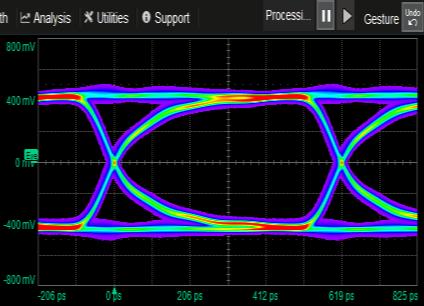
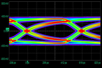
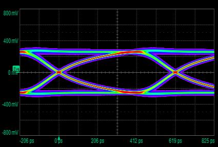
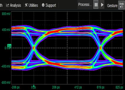
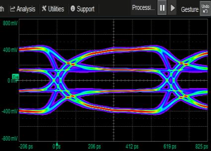
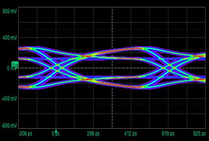
5 EYE Diagram & Jitter EYE Diagram Testing RBR and HBR: TP2 HBR: TP3_EQ (emulated in Analyzer SW from TP2 acquisition) HBR2: TP3_EQ (emulated in Analyzer SW from TP2 acquisition) HBR3: TP3_EQ (emulated in Analyzer SW from TP2 acquisition) The EYE Diagram test shall pass the TP3_EQ test point using both a worst case and a zero length cable model as described below. It is required that the source provides at least one unique setting (Voltage Swing, Pre-Emphasis Level, Post-Cursor2 Level, and Equalization) that will pass each cable model. 07/14/2017 5

6 EYE Diagram Eye pattern computation D+ Diff = D+ - D- D- Eye 07/14/2017 6


7 EYE Diagram Eye pattern computation PLL CLK Main Link: Second-order clock recovery function with a closed loop tracking bandwidth of 10MHz with a damping factor of 1.00 for HBR2 10MHz with a damping factor of 1.51 for HBR 5.4MHz with a damping factor of 1.51 for RBR UI=one bit time 07/14/2017 7


8 EYE Diagram TP2 Connection for Source Compliance Tests TP2 TP2 TP3 Worst Cable D+ TP3 Worst Cable + EQ TX D+ 07/14/2017 8
9 Transmitter De-emphasis Loss and Channel BW - Worst Cable Model Transmitter Receiver TP2 TP3 TX Cable RX 07/14/2017 9
10 Transmitter De-emphasis Loss and Channel BW - Worst Cable Model Transmitter Receiver TP2 TP3 TX Cable RX 07/14/
11 Transmitter De-emphasis De-emphasis and Worst Cable model 0dB 3.5dB 6dB 9.5dB 07/14/
, for example Tj=n*Rj + Dj (BER=10-9) Tj 07/14/2017 12")
12 Jitter Measurement Total jitter(tj) is a measure of the maximum peak-to-peak jitter at a specified bit error rate (BER), for example Tj=n*Rj + Dj (BER=10-9) Tj 07/14/


13 Jitter Measurement Deterministic Jitter Obtain DJ PDF via deconvolution and associated pk-pk (directly from jitter PDF, or derivative of BER CDF) 07/14/
14 Jitter Measurement Tj, Rj and Dj & Non ISI Jitter Measurements 07/14/
15 Attributes of the Signal that can be Varied Lane, Bitrate, Pre-emphasis, Amplitude, SSC, Test Pattern Bitrate Pre-emph Amplitude SSC Test Pattern mV On PLTPAT db 600mV Off D db 9.5 db 800mV 1200mV Symbol error rate pattern CP2520 HBR2 Compliance HBR3 Compliance 6/13/
16 Automation PHY Validation The QPHY-DisplayPort software provides an automated test environment for running all of the normative real-time oscilloscope tests for sources in accordance with Version 1.2b of the Video Electronics Standards Association (VESA) DisplayPort PHY Compliance Test Specification, as well as tests for HBR3 signals at 8.1 Gbps. Support for RBR, HBR, HBR2, and HBR3 bit rates (1.62 Gb/s, 2.7 Gb/s, 5.4 Gb/s, and 8.1 Gb/s) Support for testing of 1, 2 or 4 lanes 100% automated testing using Unigraf DPR-100 with AUX Control capability 07/14/


17 DP Test Fixture Wilder Technologies Key Electrical 1.35Gb/s, 2.7Gb/s, 5.4Gb/s, and 8.1Gb/s data rates supported Insertion loss < 6.5GHz / Return loss < 4.25GHz Differential Impedance 100+/-5 ohms / Single Ended Impedance 50+/-2.5 ohms 07/14/


18 AUX Controller and switch matrix Automation - Automatic configuration of DUT settings using AUX controller - Unigraf DPR-100 Reference Sink, Commands DUT via AUX lines to go into appropriate modes, No manual user-configurations required! Aux controller DPR-100 is operating as a DP AUX Controller to automate the DP PHY testing with a compliant PHY Test Equipment. With the AUX Controller firmware DPR-100 is compatible with TeledyneLeCroy oscilloscopes Switch Matrix model=usb-4spdt-a18 Mini-circuits Switch Matrix support for 4-lane testing No connect/disconnect of cabling! 6/13/


19 QualiPHY = The TOTAL PC Solution QualiPHY = QPHY = An electrical (PHY) Compliance serial data standard package SOLUTION The QualiPHY software application automates the oscilloscope setup test and report generation. Bit Rate / OutputLevel / Pre-emphasis / Pattern / SSC are configured by Aux controller 07/14/

20 Connection Diagram with Switch and AUX Controller QualiPHY displays connection diagrams to ensure tests run properly 6/13/
 07/14/2017")
21 Report (The sample of HBR3) 07/14/


22 USB Type-C DP ALT Mode Test Fixture Luxshare-ICT Type-C connector DispalyPort ALT mode Type-C to DP dongle 07/14/


23 HDMI PHY Validation 立肯科技 LeColn Technology 23

24 HDMI Basics HDMI 1.4b HDMI 2.0 Maximum bit rate 3.4 Gb/s 6.0 Gb/s Number of signals to test 3 data + 1 clock 3 data + 1 clock Required scope bandwidth 8 GHz 13 GHz Required input adapter TF-HDMI-3.3V TF-HDMI-3.3V DRAFT 6/13/
25 Test Point Descriptions The signal test points for a TMDS link are shown in below. TP1 is used for testing of HDMI Sources and Transmitter components. TP2 is used for testing of HDMI Sinks and Receiver components. TP1 and TP2 together are also used for testing of cables. TP1 TP2 TX Cable RX Source Sink 07/14/
26 HDMI1.4 TMDS Electrical Compliance 7-2: VL 7-4: TRise, TFall 7-5: Over/Undershoot (Not Mandatory) 7-6: Inter-Pair Skew 7-7: Intra-Pair Skew 7-8: Clock Duty Cycle 7-9: Clock Jitter 7-10: Data Eye Diagram 07/14/
27 HDMI2.0 TMDS Electrical Compliance HF1-1: VL and Vswing HF1-2: Trise Tfall HF1-3: Inter-pair Skew HF1-4: Intra-pair Skew HF1-5: Differential Voltage HF1-6: Clock Duty Cycle HF1-7: Clock Jitter HF1-8: Data Eye Diagram 07/14/

28 EYE Diagram TP1 Connection for Source Compliance Tests Apply the Worst Cable Emulator to measure TMDS differential signals at TP2 eye TP1 Data TX Source CLK 07/14/


29 Test fixture Wilder Technologies Key Electrical: 4.95Gb/s and 10.2Gb/s data rates supported Insertion loss < 9.6GHz / Return loss < 3.3GHz Differential Impedance 100+/-5ohms / Single Ended Impedance 50+/-2.5 ohms 29
 controller, which")
 Emulator) http://www.wilder-tech.")
30 EDID controller For compliance testing, the HDMI source must be controlled to output the correct signals for each test For those who cannot, they will need to use an Extended Display Identification Data (EDID) controller, which talks to the source over the HDMI link and tells it what to output Granite River Labs HDMI-CONT for EDID control HDMI-EDID-EMS (Source (Host) Emulator) 30


31 Switch matrix Mini-circuits RC-8SPDT-A18 rd.html?model=rc-8spdt-a18 Since HDMI testing requires both single-ended and differential measurements on 4 differential signals, we need to measure 8 signals total QPHY-HDMI2 has functionality built in to control a switch matrix for this purpose Using the switch matrix also requires a separate HDMI termination module, the Wilder Technologies HDMI-TPA-T 31

32 TF-HDMI-3.3V 50 ohms Pull-up Terminator The TF-HDMI-3.3V adapter provides the necessary 3.3 V pull-up termination for HDMI testing. The TF-HDMI-3.3V provides both a signal path through to the oscilloscope with a 3.3 V pull-up termination as well as an input that is directly terminated to 3.3 V. This is required for terminating the data lines that are not currently under test. The TF-HDMI-3.3V-QUADPAK provides four adapters and 8 SMA-SMA cables to allow for the testing of all HDMI signals (Clock, D0, D1 and D2). 07/14/


33 QualiPHY = The TOTAL PC Solution QualiPHY = QPHY = An electrical (PHY) Compliance serial data standard package SOLUTION The QualiPHY software application automates the oscilloscope setup test and report generation. QualiPHY displays connection diagrams to ensure tests run properly 07/14/

34 Report (Sample of HDMI2.0) 07/14/


35 High Speed Serial Bus Debug Section 1 - Probing LeColn, Service and Support Division 立肯科技 LeColn Technology
")

36 WaveLink Hi-BW Differential Probing System(13GHz 25GHz) Example of D2505-A-PS Teledyne LeCroy Confidential /16/
37 Platform/Cable Assembly + Amplifier Module + Interconnect Lead 1. Connecting the Amplifier Module to the Platform/Cable Assembly 2. Connecting a solder-in interconnect lead to an amplifier module NOTE: The entire SI tip should be positioned with the resistor side upright facing (away from the PCB plane). Keep a 45 degree angle between the SI tip ends and the PCB plane /14/


38 Caution: This configuration has non-standard leads added to probes which are not matched, and add inductance A probe with flat geometry and rubberized flex circuit lead can be easily secured in place Adhesive base mount Tips soldered to chip pins Probing discrete components 07/14/

39 Caution: This configuration has non-standard leads added to probes which are not matched, and add inductance When damping resistors are removed for connection to the interposer, the leads should be replaced with 3mm 34 gauge wire 07/14/


40 Caution: Using square pin or other adapters which reduce rated bandwidth can reduce measurement accuracy Square pin connectors are typically rated at 3GHz BW Solder-in tip rated at 13 GHz bandwidth 07/14/


41 Ultra-compact Size - positioner tip browser Teledyne LeCroy s Dxx05-PT positioner tip browser can be easily hand-held with the attachable wand or positioned in place with one of many standard or optional accessory mechanical positioners. 07/14/


42 High Speed Serial Bus Debug Section 2 - SDA3 (Serial Data Analysis 3) LeColn, Service and Support Division 立肯科技 LeColn Technology
43 Serial Data Jitter Analysis & Debug Requires Deep, Accurate Insight Into Jitter Breakdown Compliance Testing Tj (Total Jitter) Rj (Random Jitter) Dj (Deterministic Jitter) (Bounded Uncorrelated Jitter) BUj DDj (Data Dependent Jitter) Debug & Analysis Pj OBUj DCD ISI Periodic Jitter Other BUj Duty Cycle Distortion InterSymbol Interference 07/14/
 Block of continuous serial data")

44 Continuous Bit Eye Pattern Rendering Real Time Eye (consecutive UI) Block of continuous serial data acquired Bits are separated using software clock recovery Overlapped bits form the eye pattern 07/14/
 separately from the left and right sides to determine the cumulative probability density (CDF) The width of this curve")
45 Total Jitter Total jitter is a measure of the maximum peakto-peak jitter at a specified bit error rate (BER) The specified BER is another way of expressing a confidence interval or observation time Total jitter is determined by integrating the probability density function (PDF) separately from the left and right sides to determine the cumulative probability density (CDF) The width of this curve at the specified BER (or confidence interval) gives the total jitter Total jitter CDF 07/14/

46 Histogram Growth Source: JitterTime Consulting 07/14/

47 Jitter Components Separation of random and deterministic jitter Tj = N*Rj + Dj N = sigma value for selected BER Dj = p-p deterministic jitter Approximate heuristic formula Measure Tj at several BER values and solve for Rj and Dj Tj1 Tj2 Tj3 Tj4 07/14/
48 Jitter Analysis Component of Dj : ISI(Inter-Symbol Interference) Ideal data data Edge shift made by former data pattern is called as ISI It is typical in cases of insufficient bandwidth.

49 Jitter Analysis Component of Dj : DDj(Data Dependent jitter)
50 SDA3 = Sigtest + Advance Analysis Tools Transition Eye / Non-Transition Eye / Jitter are as same as Sigtest Transition Eye Non-Transition Eye 07/14/

51 Apply Equalization and De-embed / Emulate Fixtures & Channels SDAIII-CompleteLinQ seamlessly integrates transmitter emphasis and receiver equalization features Use EyeDoctorII or the new VirtualProbe package Emphasis, De-embed/Emulate, Equalization: EyeDoctorII EyeDoctorII-VP SDAIII-CompleteLinQ 07/14/
 07/14/2017")
52 Channel Emulation Measured at end of reference channel and cables at TP1 Before Channel Emulation After Channel Emulation Import S-parameter (S4P) 07/14/

53 Apply Equalization with Eye Doctor II SDAIII-CompleteLinQ seamlessly integrates transmitter emphasis and receiver CTLE, FFE and DFE equalizers No Equalization CTLE DFE 07/14/
, the transmitter signal typically has very good signal integrity.")

 is the signal of interest. 3.")
54 Measurement Challenge Transmitter Receiver Eq Backplane Differential Probe Differential Probe 1. For very fast data rates (>5 Gb/s), the transmitter signal typically has very good signal integrity. However, after propagating through the backplane, this signal will become severely degraded. 2. At the far end of the channel, the eye is closed. The signal at the receiver pins (which can be probed) is not the signal of interest. The equalized signal inside of the receiver chip (which cannot be probed) is the signal of interest. 3. The equalized signal within the receiver chip cannot be probed. How can this signal be validated to ensure low jitter, a clean eye pattern, and good signal integrity? 07/14/

55 EyeDoctor II and VirtualProbe Signal Integrity Tools 07/14/
 LeColn, Service and Support Division 立肯科技 LeColn")
56 High Speed Serial Bus Debug Section 3 WaveScan (Advanced Search and Analysis) LeColn, Service and Support Division 立肯科技 LeColn Technology
 is only 29ps?")
57 Auto Parameters, but not smart Scope captures lots of cycles, Why Rise Time(20%-80%) is only 29ps? 07/14/
58 Smart Parameter Statistic ON = Full Cycles/Screen measurement First screen = 24,832 Statistic num = 24,832 Second screen = 24,801 Statistic num = 24,832+24,801 Third screen = 24,768 Statistic num = 24,832+24,801+24,768 Fourth screen = 24,866 Statistic num = 24,832+24,801+24,768+24,866...You get every Rise Times via Smart Parameter! 07/14/
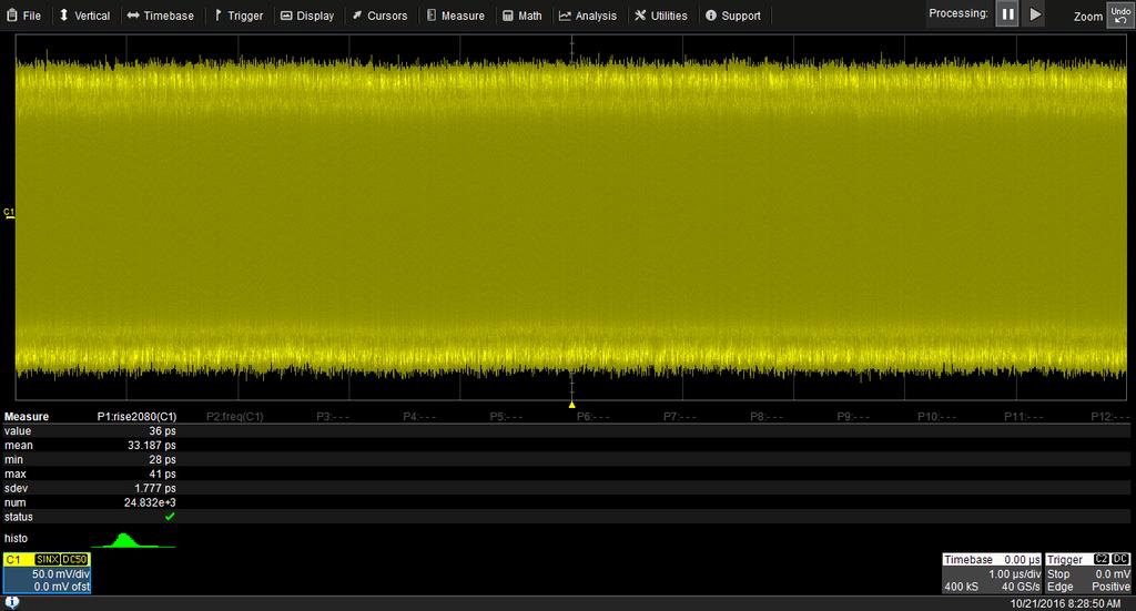
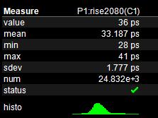


59 Smart Parameter, but hard to debug How can I view and analysis waveforms >40ps Rise Time(20%-80%)? 07/14/


60 Wavescan = Smart Waveform scan capability Scans for an event in many acquisitions over a long period of time. It support 6 search modes, apply a search condition and begin scanning is very simple. 07/14/

61 Finds Problems That Triggers Won't Find A Teledyne LeCroy X-Stream oscilloscope will quickly scan millions of events, looking for unusual occurrences, and do it much faster and more efficiently than other oscilloscopes can /14/

")

62 High Speed Serial Bus Debug Section 4 LabNotebook (Flashback tool) LeColn, Service and Support Division 立肯科技 LeColn Technology

63 A Complete In-scope Solution - Documentation Our users can efficiently create complete and detailed waveform reports directly in the oscilloscope. An allin-one solution for annotating and sharing information, LabNotebook simplifies results recording and report generation by eliminating the multi-step processes that often involve several pieces of equipment. Save Waveforms = Keep Datas Save Table = Keep Parameters values Save Setup = Keep scope setups Print Screen = Keep the pictures Labnotebook = Save waveforms + Table + Setup + Print Screen And + Report Generator 07/14/


64 A Complete In-scope Solution - Documentation Flashback is one of the most powerful features in LeCroy s LabNotebook documentation tool. Not only does LabNotebook save a report of a user selected test, it also can store the acquired waveforms and oscilloscope setup. If you find yourself in the position of having not taken a specific measurement during the test, with Flashback you can recall the data and make additional measurements. 07/14/

65 Customize Report Generator LabNotebook enables the users to focus on results : Save all display waveforms Save the relevant DSO setup with saved waveforms Add freehand notes with a stylus Convert the complete report to PDF,HTML,RTF Print or reports 07/14/
")


66 I forgot to measure Fall Time(20%-80%) before Power Off Fortunately, You created a Labnotebook entry before Power Off 07/14/
DisplayPort TX & RX Testing Solutions
 DisplayPort TX & RX Testing Solutions Agenda DP Technology Overview DPC TX Solution DPC RX Solution 2 DP Technology Overview 3 DisplayPort Standards Standards DP 1.2 May, 2012 DP over Type-C Spec Aug,
SDAIII-CompleteLinQ Multi-Lane Serial Data, Noise and Crosstalk Analysis
 SDAIII-CompleteLinQ Multi-Lane Serial Data, Noise and Crosstalk Analysis TOOLS TO MEET SERIAL DATA ANALYSIS CHALLENGES Key Features Most complete jitter decomposition, eye diagram and analysis tools Up
QPHY-HDMI2 Operator s Manual
 QPHY-HDMI2 Operator s Manual Revision B November, 2017 Relating to: XStreamDSO Version 8.5.x.x QualiPHY Version 8.5.x.x 700 Chestnut Ridge Road Chestnut Ridge, NY, 10977-6499 Tel: (845) 425-2000, Fax:
DisplayPort Standard. Agilent, Inc. Draft2 January 14, 2013
 Agilent, Inc. DisplayPort Standard Draft2 January 14, 2013 Agilent MOI for DisplayPort PHY CTS 1.2b Source Testing Using DSA90000A/90000X/90000Q Series Oscilloscopes with U7232B DisplayPort Compliance
Draft Baseline Proposal for CDAUI-8 Chipto-Module (C2M) Electrical Interface (NRZ)
 Electrical Interface (NRZ)") Draft Baseline Proposal for CDAUI-8 Chipto-Module (C2M) Electrical Interface (NRZ) Authors: Tom Palkert: MoSys Jeff Trombley, Haoli Qian: Credo Date: Dec. 4 2014 Presented: IEEE 802.3bs electrical interface
Draft Baseline Proposal for CDAUI-8 Chipto-Module (C2M) Electrical Interface (NRZ) Authors: Tom Palkert: MoSys Jeff Trombley, Haoli Qian: Credo Date: Dec. 4 2014 Presented: IEEE 802.3bs electrical interface
Eye Doctor II Advanced Signal Integrity Tools
 Eye Doctor II Advanced Signal Integrity Tools EYE DOCTOR II ADVANCED SIGNAL INTEGRITY TOOLS Key Features Eye Doctor II provides the channel emulation and de-embedding tools Adds precision to signal integrity
Tektronix Inc. DisplayPort Standard
 DisplayPort Standard 06-12-2008 DisplayPort Standard Tektronix MOI for Sink Tests (AWG Jitter Generation using Direct Synthesis and calibration using Real Time DPO measurements for Sink Devices) DisplayPort
QPHY-USB3 USB3.0 Serial Data Operator s Manual
 QPHY-USB3 USB3.0 Serial Data Operator s Manual Revision A April, 2009 Relating to the Following Release Versions: Software Option Rev. 5.8 USB3 Script Rev. 1.0 Style Sheet Rev. 1.2 LeCroy Corporation 700
Combating Closed Eyes Design & Measurement of Pre-Emphasis and Equalization for Lossy Channels
 Combating Closed Eyes Design & Measurement of Pre-Emphasis and Equalization for Lossy Channels Why Test the Receiver? Serial Data communications standards have always specified both the transmitter and
Combating Closed Eyes Design & Measurement of Pre-Emphasis and Equalization for Lossy Channels
 Combating Closed Eyes Design & Measurement of Pre-Emphasis and Equalization for Lossy Channels Why Test the Receiver? Serial Data communications standards have always specified both the transmitter and
Keysight Technologies M8048A ISI Channels
 Keysight Technologies M8048A ISI Channels Master Your Next Designs Data Sheet Key features Emulate a wide range of channel loss with cascadable ISI traces with fine resolution 4 short (7.7 to 12.8 ) and
Next Generation 인터페이스테크놀로지트렌드
 Next Generation 인터페이스테크놀로지트렌드 (USB3.1, HDMI2.0, MHL3.2) 텍트로닉스박영준부장 Agenda USB3.1 Compliance Test update What s different for USB3.1 Transmitter and Receiver Compliance Test HDMI2.0, MHL3.2 overview Q &
PAM4 signals for 400 Gbps: acquisition for measurement and signal processing
 TITLE PAM4 signals for 400 Gbps: acquisition for measurement and signal processing Image V1.00 1 Introduction, content High speed serial data links are in the process in increasing line speeds from 25
Keysight Method of Implementation (MOI) for VESA DisplayPort (DP) Standard Version 1.3 Cable-Connector Compliance Tests Using E5071C ENA Option TDR
 for VESA DisplayPort (DP) Standard Version 1.3 Cable-Connector Compliance Tests Using E5071C ENA Option TDR") Revision 1.00 February 27, 2015 Keysight Method of Implementation (MOI) for VESA DisplayPort (DP) Standard Version 1.3 Cable-Connector Compliance Tests Using E5071C ENA Option TDR 1 Table of Contents 1.
Revision 1.00 February 27, 2015 Keysight Method of Implementation (MOI) for VESA DisplayPort (DP) Standard Version 1.3 Cable-Connector Compliance Tests Using E5071C ENA Option TDR 1 Table of Contents 1.
Agilent E4887A HDMI TMDS Signal Generator Platform
 Agilent E4887A HDMI TMDS Signal Generator Platform Data Sheet Version 1.9 Preliminary E4887A- 007 E4887A- 037 E4887A- 003 Page Convenient Compliance Testing and Characterization of HDMI 1.3 Devices The
Practical De-embedding for Gigabit fixture. Ben Chia Senior Signal Integrity Consultant 5/17/2011
 Practical De-embedding for Gigabit fixture Ben Chia Senior Signal Integrity Consultant 5/17/2011 Topics Why De-Embedding/Embedding? De-embedding in Time Domain De-embedding in Frequency Domain De-embedding
PCI Express. Francis Liu Project Manager Agilent Technologies. Nov 2012
 PCI Express Francis Liu Project Manager Agilent Technologies Nov 2012 PCI Express 3.0 Agilent Total Solution Physical layer interconnect design Physical layertransmitter test Physical layerreceiver test
M809256PA OIF-CEI CEI-56G Pre-Compliance Receiver Test Application
 M809256PA OIF-CEI CEI-56G Pre-Compliance Receiver Test Application Find us at www.keysight.com Page 1 Table of Contents Key Features... 3 Description... 3 Calibrations and Tests Covered by M809256PA Pre-Compliance
Receiver Testing to Third Generation Standards. Jim Dunford, October 2011
 Receiver Testing to Third Generation Standards Jim Dunford, October 2011 Agenda 1.Introduction 2. Stressed Eye 3. System Aspects 4. Beyond Compliance 5. Resources 6. Receiver Test Demonstration PCI Express
100G EDR and QSFP+ Cable Test Solutions
 100G EDR and QSFP+ Cable Test Solutions (IBTA, 100GbE, CEI) DesignCon 2017 James Morgante Anritsu Company Presenter Bio James Morgante Application Engineer Eastern United States james.morgante@anritsu.com
SV1C Personalized SerDes Tester
 SV1C Personalized SerDes Tester Data Sheet SV1C Personalized SerDes Tester Data Sheet Revision: 1.0 2013-02-27 Revision Revision History Date 1.0 Document release Feb 27, 2013 The information in this
Switching Solutions for Multi-Channel High Speed Serial Port Testing
 Switching Solutions for Multi-Channel High Speed Serial Port Testing Application Note by Robert Waldeck VP Business Development, ASCOR Switching The instruments used in High Speed Serial Port testing are
Prepare for Next Generation USB Technology Testing
 Prepare for Next Generation USB Technology Testing Disclaimer The USB 3.1 compliance test requirements are not final therefore all opinions, judgments, recommendations, etc., that are presented herein
SPARQ Signal Integrity Network Analyzer. High-bandwidth, Multi-port S-parameters
 SPARQ High-bandwidth, Multi-port S-parameters SPARQ: S-PARAmeteRS Quick Key Features Provides complete S-parameter measurements on up to 12 ports Mmeasures from DC to 40 GHz One-button-press internal OSLT
USB 3.1 ENGINEERING CHANGE NOTICE
 Title: SSP System Jitter Budget Applied to: USB_3_1r1.0_07_31_2013 Brief description of the functional changes: Change to the 10Gbps system jitter budget. The change reduces the random jitter (RJ) budget
The Measurement Tools and What They Do
 2 The Measurement Tools The Measurement Tools and What They Do JITTERWIZARD The JitterWizard is a unique capability of the JitterPro package that performs the requisite scope setup chores while simplifying
Datasheet SHF A
 SHF Communication Technologies AG Wilhelm-von-Siemens-Str. 23D 12277 Berlin Germany Phone +49 30 772051-0 Fax ++49 30 7531078 E-Mail: sales@shf.de Web: http://www.shf.de Datasheet SHF 19120 A 2.85 GSa/s
DisplayPort 1.4 Link Layer Compliance
 DisplayPort 1.4 Link Layer Compliance Neal Kendall Product Marketing Manager Teledyne LeCroy quantumdata Product Family neal.kendall@teledyne.com April 2018 Agenda DisplayPort 1.4 Source Link Layer Compliance
ELECTRICAL PERFORMANCE REPORT
 CIRCUITS & DESIGN ELECTRICAL PERFORMANCE REPORT DENSIPAC 4 ROW Date: 06-12-2006 Circuits & Design EMEA Circuits & Design 1/21 06/12/2006 1 INTRODUCTION... 3 2 CONNECTORS, TEST BOARDS AND TEST EQUIPMENT...
12G-SDI Physical Layer Analysis using the Ultra 4K Tool Box
 12G-SDI Physical Layer Analysis using the Ultra 4K Tool Box Authors: Alan Wheable FISTC, MITOL Senior Technical Author, Alex Huntley MEng Senior Consultant and Andy McMinn BEng Senior Consultant at Omnitek
BRR Tektronix BroadR-Reach Compliance Solution for Automotive Ethernet. Anshuman Bhat Product Manager
 BRR Tektronix BroadR-Reach Compliance Solution for Automotive Ethernet Anshuman Bhat Product Manager anshuman.bhat@tektronix.com Agenda BroadR-Reach Automotive Market Technology Overview Open Alliance
Emphasis, Equalization & Embedding
 Emphasis, Equalization & Embedding Cleaning the Rusty Channel Gustaaf Sutorius Application Engineer Agilent Technologies gustaaf_sutorius@agilent.com Dr. Thomas Kirchner Senior Application Engineer Digital
Next Generation Ultra-High speed standards measurements of Optical and Electrical signals
 Next Generation Ultra-High speed standards measurements of Optical and Electrical signals Apr. 2011, V 1.0, prz Agenda Speeds above 10 Gb/s: Transmitter and Receiver test setup Transmitter Test 1,2 : Interconnect,
Features. For price, delivery, and to place orders, please contact Hittite Microwave Corporation:
 HMC-C1 Typical Applications The HMC-C1 is ideal for: OC-78 and SDH STM-25 Equipment Serial Data Transmission up to 5 Gbps Short, intermediate, and long haul fiber optic applications Broadband Test and
Dual Link DVI Receiver Implementation
 Dual Link DVI Receiver Implementation This application note describes some features of single link receivers that must be considered when using 2 devices for a dual link application. Specific characteristics
32 G/64 Gbaud Multi Channel PAM4 BERT
 Product Introduction 32 G/64 Gbaud Multi Channel PAM4 BERT PAM4 PPG MU196020A PAM4 ED MU196040A Signal Quality Analyzer-R MP1900A Series Outline of MP1900A series PAM4 BERT Supports bit error rate measurements
10Gbps SFP+ Optical Transceiver, 10km Reach
 10Gbps SFP+ Optical Transceiver, 10km Reach Features Optical interface compliant to IEEE 802.3ae 10GBASE-LR Electrical interface compliant to SFF-8431 Hot Pluggable 1310nm DFB transmitter, PIN photo-detector
WAVEEXPERT SERIES OSCILLOSCOPES WE 9000 NRO 9000 SDA 100G. The World s Fastest Oscilloscope
 WAVEEXPERT SERIES OSCILLOSCOPES WE 9000 NRO 9000 SDA 100G The World s Fastest Oscilloscope The Fastest Oscilloscope in the Marketplace The WaveExpert and SDA 100G are the first instruments to combine the
EVALUATION KIT AVAILABLE Multirate SMPTE SD/HD Cable Driver with Selectable Slew Rate TOP VIEW +3.3V. 10nF IN+ IN- MAX3812 SD/HD GND RSET +3.
 19-3571; Rev ; 2/5 EVALUATION KIT AVAILABLE Multirate SMPTE SD/HD Cable Driver General Description The is a multirate SMPTE cable driver designed to operate at data rates up to 1.485Gbps, driving one or
How advances in digitizer technologies improve measurement accuracy
 How advances in digitizer technologies improve measurement accuracy Impacts of oscilloscope signal integrity Oscilloscopes Page 2 By choosing an oscilloscope with superior signal integrity you get the
MSO-28 Oscilloscope, Logic Analyzer, Spectrum Analyzer
 Link Instruments Innovative Test & Measurement solutions since 1986 Store Support Oscilloscopes Logic Analyzers Pattern Generators Accessories MSO-28 Oscilloscope, Logic Analyzer, Spectrum Analyzer $ The
SV1C Personalized SerDes Tester. Data Sheet
 SV1C Personalized SerDes Tester Data Sheet Table of Contents 1 Table of Contents Table of Contents Table of Contents... 2 List of Figures... 3 List of Tables... 3 Introduction... 4 Overview... 4 Key Benefits...
WAVEEXPERT 100H. Wide Bandwidth Oscilloscopes for the Next Generation Serial Data Standards
 WAVEEXPERT 100H Wide Bandwidth Oscilloscopes for the Next Generation Serial Data Standards The New WaveExpert 100H Sampling Oscilloscope the Complete Workstation for Optimizing Serial Data Signal Integrity
HMC958LC5 HIGH SPEED LOGIC - SMT. Typical Applications. Features. Functional Diagram. General Description
 Typical Applications Features The HMC958LC5 is ideal for: SONET OC-192 and 1 GbE 16G Fiber Channel 4:1 Multiplexer Built-In Test Broadband Test & Measurement Functional Diagram Supports High Data Rates:
PicoScope 6407 Digitizer
 YE AR PicoScope 6407 Digitizer HIGH PERFORMANCE USB DIGITIZER Programmable and Powerful 1 GHz bandwidth 1 GS buffer size 5 GS/s real-time sampling Advanced digital triggers Built-in function generator
ASNT_PRBS20B_1 18Gbps PRBS7/15 Generator Featuring Jitter Insertion, Selectable Sync, and Output Amplitude Control
 ASNT_PRBS20B_1 18Gbps PRBS7/15 Generator Featuring Jitter Insertion, Selectable Sync, and Output Amplitude Control Broadband frequency range from 20Mbps 18.0Gbps Minimal insertion jitter Fast rise and
Agilent MOI for HDMI 1.4b Cable Assembly Test Revision Jul 2012
 Revision 1.11 19-Jul 2012 Agilent Method of Implementation (MOI) for HDMI 1.4b Cable Assembly Test Using Agilent E5071C ENA Network Analyzer Option TDR 1 Table of Contents 1. Modification Record... 4 2.
Jitter and Eye Fundamental & Application. Jacky Huang AE, Tektronix Taiwan
 Jitter and Eye Fundamental & Application Jacky Huang AE, Tektronix Taiwan Agenda Background Information Jitter Basics What is Jitter? TIE vs. Period Jitter vs. Cycle-to-Cycle Clock Recovery Jitter Visualization
SFP-10G-LR (10G BASE-LR SFP+) Datasheet
 Datasheet") SFP-10G-LR (10G BASE-LR SFP+) Datasheet Features Supports rate from 1.25 Gb/ to 10.3 Gb/s bit rates Optical interface compliant to IEEE 802.3ae Electrical interface compliant to SFF-8431 1310nm DFB transmitter,
SFP-10G-LR (10G BASE-LR SFP+) Datasheet Features Supports rate from 1.25 Gb/ to 10.3 Gb/s bit rates Optical interface compliant to IEEE 802.3ae Electrical interface compliant to SFF-8431 1310nm DFB transmitter,
Analyzing 8b/10b Encoded Signals with a Real-time Oscilloscope Real-time triggering up to 6.25 Gb/s on 8b/10b encoded data streams
 Presented by TestEquity - www.testequity.com Analyzing 8b/10b Encoded Signals with a Real-time Oscilloscope Real-time triggering up to 6.25 Gb/s on 8b/10b encoded data streams Application Note Application
10Gb/s SFP+ ER 1550nm Cooled EML with TEC, PIN Receiver 40km transmission distance
 Feature 10Gb/s serial optical interface compliant to 802.3ae 10GBASE-ER/EW Electrical interface compliant to SFF-8431 specifications for enhanced 8. and 10 Gigabit small form factor pluggable module SFP+
HMC-C060 HIGH SPEED LOGIC. 43 Gbps, D-TYPE FLIP-FLOP MODULE. Features. Typical Applications. General Description. Functional Diagram
 HMC-C Features Typical Applications The HMC-C is ideal for: OC-78 and SDH STM-25 Equipment Serial Data Transmission up to 43 Gbps Digital Logic Systems up to 43 Gbps Broadband Test and Measurement Functional
MIPI DigRF 3G and v4 Decode
 MIPI DigRF 3G and v4 Decode Key Features DigRF v4 Decodes Low-speed (26 Mb/s) Medium-speed (1248 Mb/s) High-speed (1456 Mb/s) View an entire DigRF 3G burst using intuitive decoding and table display. Click
X-Stream DSO Version 3.6 Release Notes
 X-Stream DSO Version 3.6 Release Notes probe calibration and deskew fixture This release contains support for LeCroy s new TF-DSQ option. The fixture enables DC gain, offset, and skew calibration at the
o-microgigacn Data Sheet Revision Channel Optical Transceiver Module Part Number: Module: FPD-010R008-0E Patch Cord: FOC-CC****
 o-microgigacn 4-Channel Optical Transceiver Module Part Number: Module: FPD-010R008-0E Patch Cord: FOC-CC**** Description Newly developed optical transceiver module, FUJITSU s o-microgigacn series supports
SDLA Visualizer Serial Data Link Analysis Visualizer Software Printable Application Help
 SDLA Visualizer Serial Data Link Analysis Visualizer Software Printable Application Help *P076017306* 076-0173-06 SDLA Visualizer Serial Data Link Analysis Visualizer Software Printable Application Help
De-embedding Gigaprobes Using Time Domain Gating with the LeCroy SPARQ
 De-embedding Gigaprobes Using Time Domain Gating with the LeCroy SPARQ Dr. Alan Blankman, Product Manager Summary Differential S-parameters can be measured using the Gigaprobe DVT30-1mm differential TDR
Systematic Tx Eye Mask Definition. John Petrilla, Avago Technologies March 2009
 Systematic Tx Eye Mask Definition John Petrilla, Avago Technologies March 2009 Presentation Overview Problem statement & solution Comment Reference: P802.3ba D1.2, Comment 97 Reference Material Systematic
Using Allegro PCB SI GXL to Make Your Multi-GHz Serial Link Work Right Out of the Box
 Using Allegro PCB SI GXL to Make Your Multi-GHz Serial Link Work Right Out of the Box Session 8.11 - Hamid Kharrati - A2e Technologies Agenda About the Project Modeling the System Frequency Domain Analysis
PicoScope 6407 Digitizer
 YE AR HIGH PERFORMANCE USB DIGITIZER Programmable and Powerful 1 GHz bandwidth 1 GS buffer size 5 GS/s real-time sampling Advanced digital triggers Built-in function generator USB-connected Signals Analysis
Agilent 86100C Infiniium DCA-J
 Agilent 86100C Infiniium DCA-J The fastest way to the right answer Time Domain Reflectometer Digital Communications Analyzer The multi-functional analysis tool Wide Band Oscilloscope Jitter Analyzer DCA-J:
Physical Layer Compliance Testing for HDMI 1.4a Using TDSHT3 HDMI Compliance Test Software
 Physical Layer Compliance Testing for HDMI 1.4a Using TDSHT3 HDMI Compliance Test Software Application Note Introduction Termed as the catalyst for the DTV revolution, High-Definition Multimedia Interface
Agilent N6467A BroadR-Reach Compliance Test Application. Methods of Implementation
 Agilent N6467A BroadR-Reach Compliance Test Application Methods of Implementation s1 Notices Agilent Technologies, Inc. 2013 No part of this manual may be reproduced in any form or by any means (including
New Serial Link Simulation Process, 6 Gbps SAS Case Study
 ew Serial Link Simulation Process, 6 Gbps SAS Case Study Donald Telian SI Consultant Session 7-TH2 Donald Telian SI Consultant About the Authors Donald Telian is an independent Signal Integrity Consultant.
SUNSTAR 微波光电 TEL: FAX: v HMC750LP4 / 750LP4E 12.5 Gbps LIMITING AMPLIFIER
 Typical Applications The HMC75LP4(E) is ideal for: OC-192 Receivers Gbps Ethernet Receivers Gbps Fiber Channel Receivers Broadband Test & Measurement Functional Diagram Features Electrical Specifications,
C-PHY Essentials Transmitter Test Solution TekExpress C-PHY Essentials Tx
 C-PHY Essentials Transmitter Test Solution TekExpress C-PHY Essentials Tx Applications Camera CMOS Image sensors Display Driver ICs Application processor for Mobile devices Tektronix C-PHY TX Essentials
Solutions to Embedded System Design Challenges Part II
 Solutions to Embedded System Design Challenges Part II Time-Saving Tips to Improve Productivity In Embedded System Design, Validation and Debug Hi, my name is Mike Juliana. Welcome to today s elearning.
SignalTap Plus System Analyzer
 SignalTap Plus System Analyzer June 2000, ver. 1 Data Sheet Features Simultaneous internal programmable logic device (PLD) and external (board-level) logic analysis 32-channel external logic analyzer 166
CDAUI-8 Chip-to-Module (C2M) System Analysis #3. Ben Smith and Stephane Dallaire, Inphi Corporation IEEE 802.3bs, Bonita Springs, September 2015
 System Analysis #3. Ben Smith and Stephane Dallaire, Inphi Corporation IEEE 802.3bs, Bonita Springs, September 2015") CDAUI-8 Chip-to-Module (C2M) System Analysis #3 Ben Smith and Stephane Dallaire, Inphi Corporation IEEE 802.3bs, Bonita Springs, September 2015 Supporters Ali Ghiasi, Ghiasi Quantum LLC Marco Mazzini,
CDAUI-8 Chip-to-Module (C2M) System Analysis #3 Ben Smith and Stephane Dallaire, Inphi Corporation IEEE 802.3bs, Bonita Springs, September 2015 Supporters Ali Ghiasi, Ghiasi Quantum LLC Marco Mazzini,
Keysight E4887A HDMI TMDS Signal Generator Platform. Data Sheet Version 2.1
 Keysight E4887A HDMI TMDS Signal Generator Platform Data Sheet Version 2.1 02 Keysight E4887A HDMI TMDS Signal Generator Platform - Data Sheet Convenient Compliance Testing and Characterization of HDMI
QPHY-DDR4. Instruction Manual
 QPHY-DDR4 DDR4 Serial Data Compliance Software Instruction Manual Revision C November, 2017 Relating to: XStreamDSO Version 8.5.x.x QualiPHY Version 8.5.x.x 700 Chestnut Ridge Road Chestnut Ridge, NY,
Logic Analysis Basics
 Logic Analysis Basics September 27, 2006 presented by: Alex Dickson Copyright 2003 Agilent Technologies, Inc. Introduction If you have ever asked yourself these questions: What is a logic analyzer? What
Logic Analysis Basics
 Logic Analysis Basics September 27, 2006 presented by: Alex Dickson Copyright 2003 Agilent Technologies, Inc. Introduction If you have ever asked yourself these questions: What is a logic analyzer? What
Brian Holden Kandou Bus, S.A. IEEE GE Study Group September 2, 2013 York, United Kingdom
 Simulation results for NRZ, ENRZ & PAM-4 on 16-wire full-sized 400GE backplanes Brian Holden Kandou Bus, S.A. brian@kandou.com IEEE 802.3 400GE Study Group September 2, 2013 York, United Kingdom IP Disclosure
40 Gb/s PatternPro Programmable Pattern Generator PPG4001 Datasheet
 40 Gb/s PatternPro Programmable Pattern Generator PPG4001 Datasheet Applications Semiconductor device testing Optical component testing Transceiver module testing The Tektronix PPG4001 PatternPro programmable
RX40_V1_0 Measurement Report F.Faccio
 RX40_V1_0 Measurement Report F.Faccio This document follows the previous report An 80Mbit/s Optical Receiver for the CMS digital optical link, dating back to January 2000 and concerning the first prototype
100G QSFP28 SR4 Transceiver
 Preliminary DATA SHEET CFORTH-QSFP28-100G-SR4 100G QSFP28 SR4 Transceiver CFORTH-QSFP28-100G-SR4 Overview CFORTH-QSFP28-100G-SR4 QSFP28 SR4 optical transceivers are based on Ethernet IEEE 802.3bm standard
Serial ATA International Organization
 Serial ATA International Organization Version 1.0 September 27, 2007 Serial ATA Interoperability Program Revision 1.2 Tektronix MOI for RSG Tests (Using AWG7102 and CHS Frame Error Analyzer) This document
10Gbps 10km Range SFP+ Optical Transceiver
 Page 1 of 9 Overview This 1310 nm Distributed Feedback (DFB) 10Gbps 10km Range SFP+ Optical Transceiver is designed to transmit and receive optical data over singlemode optical fiber with a link length
Memory-Depth Requirements for Serial Data Analysis in a Real-Time Oscilloscope
 Memory-Depth Requirements for Serial Data Analysis in a Real-Time Oscilloscope Application Note 1495 Table of Contents Introduction....................... 1 Low-frequency, or infrequently occurring jitter.....................
A 90 Gb/s 2:1 Multiplexer with 1 Tap FFE in SiGe Technology
 A 90 Gb/s 2:1 Multiplexer with 1 Tap FFE in SiGe Technology Ekaterina Laskin, University of Toronto Alexander Rylyakov, IBM T.J. Watson Research Center October 14 th, 2008 Paper H4 Outline Motivation System
InfiniBand Trade Association
 InfiniBand Trade Association Revision 1.02 3/30/2014 IBTA Receiver MOI for FDR Devices For Anritsu MP1800A Signal Analyzer and Agilent 86100D with module 86108B and FlexDCA S/W for stressed signal calibration
HMC-C064 HIGH SPEED LOGIC. 50 Gbps, XOR / XNOR Module. Features. Typical Applications. General Description. Functional Diagram
 HMC-C4 Features Typical Applications The HMC-C4 is ideal for: OC-78 and SDH STM-25 Equipment Serial Data Transmission up to 5 Gbps Digital Logic Systems up to 5 Gbps Broadband Test and Measurement Functional
Ethernet SFP+ QSFP+ Tx Compliance & Debug Solution SFP-TX, SFP-WDP Datasheet
 Ethernet SFP+ QSFP+ Tx Compliance & Debug Solution SFP-TX, SFP-WDP Datasheet TekExpress SFP-TX user interface for PHY measurements including SFP+ Direct Attach Cable Specifications 10GSFP+CU and QSFP+
10Gbps 10km Range 1310nm SFP+ Optical Transceiver
 Page 1 of 9 Overview ARIA s 10Gbps 10km Range 1310nm SFP+ Optical Transceiver is designed to transmit and receive optical data over single mode optical fiber with a link length of up to 10km. The transceiver
The Case of the Closing Eyes: Is PAM the Answer? Is NRZ dead?
 The Case of the Closing Eyes: Is PAM the Answer? Is NRZ dead? Agenda Introductions Overview Design Engineering Perspective Test & Measurement Perspective Summary Audience Discussion Panelists Cathy Liu
40 Gb/s PatternPro Programmable Pattern Generator PPG4001 Datasheet
 40 Gb/s PatternPro Programmable Pattern Generator PPG4001 Datasheet The Tektronix PPG4001 PatternPro programmable pattern generator provides stressed pattern generation for high-speed Datacom testing.
DisplayPort and HDMI Protocol Analysis and Compliance Testing
 DisplayPort and HDMI Protocol Analysis and Compliance Testing Agenda DisplayPort DisplayPort Connection Sequence DisplayPort Link Layer Compliance Testing DisplayPort Main Link Protocol Analysis HDMI HDMI
Agilent Technologies Pulse Pattern and Data Generators Digital Stimulus Solutions
 Agilent Technologies Pattern and Data Generators Digital Stimulus Solutions Leading pulse, pattern, data and clock generation for all test needs in digital design and manufacturing Pattern Generators Agilent
80SJNB Jitter, Noise, BER, and Serial Data Link Analysis (SDLA) Software Printable Application Help
 Software Printable Application Help") xx ZZZ 80SJNB Jitter, Noise, BER, and Serial Data Link Analysis (SDLA) Software Printable Application Help *P077064106* 077-0641-06 ZZZ 80SJNB Jitter, Noise, BER, and Serial Data Link Analysis (SDLA)
xx ZZZ 80SJNB Jitter, Noise, BER, and Serial Data Link Analysis (SDLA) Software Printable Application Help *P077064106* 077-0641-06 ZZZ 80SJNB Jitter, Noise, BER, and Serial Data Link Analysis (SDLA)
80SJNB Jitter, Noise, BER, and Serial Data Link Analysis (SDLA) Software Printable Application Help
 Software Printable Application Help") xx ZZZ 80SJNB Jitter, Noise, BER, and Serial Data Link Analysis (SDLA) Software Printable Application Help *P077064104* 077-0641-04 ZZZ 80SJNB Jitter, Noise, BER, and Serial Data Link Analysis (SDLA)
xx ZZZ 80SJNB Jitter, Noise, BER, and Serial Data Link Analysis (SDLA) Software Printable Application Help *P077064104* 077-0641-04 ZZZ 80SJNB Jitter, Noise, BER, and Serial Data Link Analysis (SDLA)
DATA SHEET. Two (2) fibers Detachable HDMI 2.0 Extender,
 fibers Detachable HDMI 2.0 Extender,") DATA SHEET Two (2) fibers Detachable HDMI 2.0 Extender, HDFX-300-TR Contents Description Features Applications Technical Specifications Operating Conditions Drawing of Module Drawing of Cable Connection
DATA SHEET Two (2) fibers Detachable HDMI 2.0 Extender, HDFX-300-TR Contents Description Features Applications Technical Specifications Operating Conditions Drawing of Module Drawing of Cable Connection
The Effect of Inserted ISI on Transition Density Plots and DCD & ISI Histograms of MJS Patterns
 The Effect of Inserted ISI on Transition Density Plots and DCD & ISI Histograms of MJS Patterns By Wavecrest Corporation TABLE OF CONTENTS: I. INTRODUCTION. 2 II. EQUIPMENT SETUP.. 3 III. TEST PROCEDURE
EMPOWERFIBER 10Gbps 2km SFP+ Optical Transceiver EPP C
 EMPOWERFIBER 10Gbps 2km SFP+ Optical Transceiver EPP-31192-02C Features Optical interface compliant to IEEE 802.3ae 10GBASE-LR Electrical interface compliant to SFF-8431 Hot Pluggable 1310nm FP transmitter,
10Gb/s SFP+ Optical Transceiver Module 10GBASE-LR/LW
 10Gb/s SFP+ Optical Transceiver Module 10GBASE-LR/LW Features 10Gb/s serial optical interface compliant to 802.3ae 10GBASE LR Electrical interface compliant to SFF 8431 specifications for enhanced 8.5
40G SWDM4 MSA Technical Specifications Optical Specifications
 40G SWDM4 MSA Technical Specifications Specifications Participants Editor David Lewis, LUMENTUM The following companies were members of the SWDM MSA at the release of this specification: Company Commscope
ASNT8140. ASNT8140-KMC DC-23Gbps PRBS Generator with the (x 7 + x + 1) Polynomial. vee. vcc qp. vcc. vcc qn. qxorp. qxorn. vee. vcc rstn_p.
 Polynomial. vee. vcc qp. vcc. vcc qn. qxorp. qxorn. vee. vcc rstn_p.") ASNT8140-KMC DC-23Gbps PRBS Generator with the (x 7 + x + 1) Polynomial Full-length (2 7-1) pseudo-random binary sequence (PRBS) generator DC to 23Gbps output data rate Additional output delayed by half
ASNT8140-KMC DC-23Gbps PRBS Generator with the (x 7 + x + 1) Polynomial Full-length (2 7-1) pseudo-random binary sequence (PRBS) generator DC to 23Gbps output data rate Additional output delayed by half
Simplifying HDMI Compliance Testing
 Simplifying HDMI Compliance Testing Tektronix Support for HDMI 1.3c and 1.4 Test Solutions 泰克中国区应用工程师 Bright Zeng Agenda HDMI Overview and Updates Compliance Test Support from Tektronix Source Tests Sink
The Challenges of Measuring PAM4 Signals
 TITLE The Challenges of Measuring PAM4 Signals Panelists: Doug Burns, SiSoft Stephen Mueller, Teledyne LeCroy Luis Boluña, Keysight Technologies Mark Guenther, Tektronix Image Jose Moreira, Advantest Martin
100GBASE-SR4 Extinction Ratio Requirement. John Petrilla: Avago Technologies September 2013
 100GBASE-SR4 Extinction Ratio Requirement John Petrilla: Avago Technologies September 2013 Presentation Summary Eye displays for the worst case TP1 and Tx conditions that were used to define Clause 95