Builders guide Kinetic Aerial Air-Ro
|
|
|
- Dwight Parks
- 5 years ago
- Views:
Transcription

1 Builders guide Kinetic Aerial Air-Ro Safety First Please build, fly and configure your drone safely. Moving propellers and mishandled lithium batteries can cause serious damage to person and property. It is your responsibility to operate safely when flying and handling your drone! Some related external resources (by no means exhaustive!): - The Home of British FPV Racing Dronesafe
2 Why build this quad? Somewhere late inch quads were becoming popular, then Rotor Riot reviewed a 4 inch and were quite unimpressed. Generally, the point was that 4 inch quads were basically 5 inch quads with half an inch cut off each arm and smaller props. They had considerably less thrust and were barely any lighter. Since then a number of things have come in to play; motors have improved considerably, smaller and lighter components have become available and frame manufacturers have started producing 4 inch quads that are designed as 4 inch quads, not sawn offs. On top of that EASA and UK law are both lining up to make life difficult for anything weighing more than 250 grams. Building a quad like this produces something that flies like a 5 inch quad with under 250 grams weight. Although I say like, I should say I prefer it. The top speed is pretty similar. However, agility is much better, I have alternated LiPos between one of these and a 5 inch racer, in comparison the 5 inch is like driving a bus. The Theory Building 5 inch quads there is a temptation to put bigger, more powerful motors on things, heavier props and generally look for the max. Building a superlight 4 inch is a different mindset. Weight matters, this quad will be half the weight of a 5 inch racer, its motors produce less thrust than the latest Carlos Fandango Super-Wide Motors but only by about a third, so the thrust to weight ratio is actually better. With less weight it carries less inertia, cornering is much quicker and crashes produce less force and therefore less damage. There is a temptation to start looking at 1806 motors, if you do that you add the extra weight of the bigger motors, about 4 or 5 grams each, but you also increase the amp draw and need a bigger LiPo, suddenly you have added 60-80grams to the quad, don t do it. Parts list Frame: Kinetic Aerial Air-Ro 3mm Flight Stack: HGLRC XJB F428 With TX20 VTX Motors: T-Motor F20ii 3750Kv Props: HQ 4x4.3x3V1S Camera: RunCam Micro Swift Receiver: FrSky XM+ LiPos: Tattu 650mAh 4s 75C Ancillary Parts: 470uf 25V Low ESR Capacitor. XT30 connector, wires, heat shrink, small zip ties Optional Hop up parts: Demonrc Vee antenna, 4x M2x6 cap head bolts and washers, Forevertube over the standoff antenna mounts.
3 Tools: Soldering iron and solder, side trimmers, craft knife, hot glue gun, hex drivers, blue threadlock Other useful stuff: files and wet-and-dry paper, hot air gun, tweezers. Preparation and Dry Build The first thing to decide is if you want to chamfer the edges of the carbon parts. If so, in a bucket of water, because carbon dust is bad for your lungs, file off the edges of the carbon parts and if you want it really neat then use wet and dry paper to smooth it off. Even if you don t intend to do this it is a good ideal to do it at the points on the bottom pate where the battery strap will run to prevent the strap wearing on it. Next take the battery pad, remove all the cur out sections before removing the backing paper, then carefully take off the backing paper and stick the pad to the bottom of the bottom plate, taking care to line up the mount holes on the plate with the holes on the battery pad. Next dry build the quad, this means assembling it without any solder. The purpose of this is firstly to make sure you know where everything fits. Secondly once everything is in place wires can be cut to the right length (see wiring diagram below). Note wires should not be long, but equally should not be tight, it is always possible to cut a little more off before you solder, sticking back on is a pain. It is good practice to check the flight controller is working BEFORE soldering anything to it. Once you have soldered a board it cannot be returned to retailers. To check a flight controller, start the Betaflight configurator application from the Chrome App Store and connect the flight controller to the PC with a USB cable. Click on Connect and make sure the flight controller connects. On the Setup tab check the model picture moves in concert with physical movements you make with the flight controller. One problem you will find with the build is the stack uses M2 bolts, the mount holes on the frame are M3. To remedy this, I used metal M2x6mm cap head screws with M2 washers to hold the stack to the frame, using metals screws allows them to be tightened more without nylon ripping, an alternate approach would be to fill the holes in the base plate with hot glue or using rubber to pad them out. The next preparation step is to tin the ends of the wires and the pads that will be used. For the newer audience, this means applying solder to the pads and ends of wires in preparation for soldering the two together. Again, use the wiring diagram below to identify which pads you need to Tin. The LiPo pads on the HGLRC 4in1 ESCs are quite small, to make life easier find some copper or multistrand wire that fits through it, push it through, fold it back on its self and twist it together, then cut it off a couple of millimetres off the pad and solder it in place this gives a much bigger area to solder the XT30 pigtail to The Camera mount also can be prepped, the frame comes with three mounts, a full sized, a mini and a micro. Although we are using a micro camera the micro mount is quite big and bulky and has antenna holes that are a bit small, so we use the mini
, this type of surface mount component has a nasty habit of falling off, so hot glue")
4 mount and cut the strut that runs across the back off so it does not get in the way, leaving two parts comprising the tube that fits over the standoff and the tab the camera screws to. The final piece of prep is the TX20 VTX has a large capacitor on it (a large black cube with the number 220 on it), this type of surface mount component has a nasty habit of falling off, so hot glue this to the board. Wiring Diagram The diagram below is the wiring diagram for the Quad: ESCS:

5 Fight controller: The Build I find it easiest to do the wiring in the following order: 1. First solder the XT30 pigtail and Capacitor leads to the underside of the 4in1 ESC board. 2. Trim the arms on the capacitor and solder the leads to it (not forgetting first to put heat shrink on the wires, once the capacitor is attached, push the heat shrink over the solder joins and shrink it. 3. Without any of the aluminium spacers attached bolt the motors to the frame, put the battery strap in place and bolt the ESC board, use one nylon standoff to hold the ESC board in place, making sure it is not on the corner you are soldering on, then solder the motor wires in place. 4. Bolt the Flight controller on top of the ESC board (at this point the flight controller and ESCs can be configured and tested if you want) again using one standoff at a corner nowhere near where you are working with the soldering iron to hold the FC in place 5. Solder the camera connections to the flight controller 6. Solder the receiver wires to the flight controller
6 7. Push the (Tinned) receiver wires through the holes in the receiver and solder. 8. Heat shrink the receiver 9. Solder the VTX wires to the flight controller 10. Push the (Tinned) VTX wires through the holes in the VTX and solder in place 11. Bolt the VTX in place 12. Bolt the Aluminium spacers to the bottom plate. 13. Attach the camera to the camera mounts 14. Slide the camera mounts over the standoffs. If you are using the over the standoff antenna mounts put them in place (I cut mine in half to save weight), push the antenna through, measure how much protrudes and cut the tubes to sufficient length to protect the antenna fully and go through the mounts, slide the tubes over the antenna and push them into the mount holes. 15. Cable tie the capacitor in place (I put larger heat shrink over the cap to protect it and help the cable tie hold it in place 16. Cable tie the XT30 in place 17. The receiver is simply on its side edge between the flight control stack and the rear standoffs. It is not secured in any way, this has never been a problem however if you want it can be secured to the top plate with strong mounting tape or secured to the rear standoffs with cable ties. 18. Attach the VTX antenna to the VTX and side it through the top plate. If you are concerned about the antenna hot glue can be used to supplement the connector, although this makes it harder (but by no means impossible) to replace the antenna, or the antenna can be cable tied to the top plate, again I prefer not to do this, it encourages wear on the antenna sheath. I have not found either measure necessary, but they are there as options if you want. 19. Screw the top plate down. Once the Configuration steps are completed all the metal screws on the under side of the quad should be secured with blue threadlock. The four metal screws on the top plate could also be done however I prefer not to as these are most commonly undone to work on the quad. Configuration There are two parts to the configuration, the flying components and the FPV components. There are some good practice bits first: 1. Smoke stoppers these are frequently used on the bench, essentially a light bulb which is connected between the LiPo and the quad, the light bulb will act as a fuse and blow if a short causes high amp draw, protecting components. These are a good idea, there are plenty of guides on how to make them on the internet

7 2. PROPS -never ever ever plug the LiPo in with props on when you are working on your quad. Quite aside from any damage to your equipment, this is likely to cause a very angry, sharp and fast moving set of blades to make contact with your face or hands and result in very serious injury. Always remove the props when working on the quad, it is a pain in the bum but you do not want to learn the lesson the hard way. Make it a habit. 3. It is assumed the radio has been bound to the receiver, there are many guides available on how to do this as well as instructions that come with the receiver Configuring the Flying components The first step is to flash the flight controller with the latest version of BetaFlight, At the time of writing this is Version 3.2 RC 4. If you haven t already, install the Betaflight configurator from the chrome apps store. Start the Betaflight configurator application and plug your USB cable in. On the left had side select the third option Flash firmware On the Choose a board drop down select OMNIBUSF4 Switch on Show unstable releases On the Choose a firmware version for OMNIBUSF4 drop down select the latest version (currently RC4) Click on Load Firmware Online in the bottom towards the right, the configurator will load up the firmware. Click on Flash Firmware and the firmware will install:

8 Note if the flight controller will not go into DFU mode, connect to it (top right button), go to the CLI tab and type DFU and hit return, the flight controller will reboot into DFU mode and you can continue as above. Once the flight controller has been flashed it needs to be set up. Click Connect, Go to the setup tab and set uart1 to serial RX as shown blow, then click Save and reboot Once the flight controller has rebooted, click Connect, go to the Configuration tab, set the esc protocol to Dshot600 and enable motor stop (note motor stop is not absolutely necessary but it makes landing easy), on the left-hand side click Motor Direction is reversed as shown below:


9 Scroll down, set the PID loop frequency to 4Khz, disable barometer if enabled and give the craft a name (this will be displayed on the OSD, it is common to use the pilot name) as shown below: Scroll down, set the receiver to serial based receiver and the serial receiver provider to SBUS as shown below:
10 Scroll down, disable all features except OSD and dynamic filter as shown below and click on Save and reboot Once the Board reboots, reconnect and go to the failsafe tab, make sure stage 2 failsafe is enabled and set to drop (it should be by default but it is worth double checking) as shown below:

11 If you have rebooted, reconnect and go to the PID tuning tab. The settings below are following a tuning, they will be quite close although may need a little tweaking as every build is a little different. The Tune is set up for 4S LiPos, on 3S a couple of points can be added to P term on pitch and roll. The rates (RC Rates and S Rates) have been increased from standard. These are about what I would use for flying round a track, for freestyle I would increase the S Rates to 0.87, however rates are a very personal thing, I would suggest a beginner would probably want to start with stock rates to get used to flying. Click Save.


12 Remaining on the PID tuning tab, click on Filter Settings Set the D-Term Lowpass filter to PT1 and set both Gyro Notch filter frequencies to 0 as shown below and click Save Go to the Receiver tab,

13 Set the Channel map to TAER1234, if you are wanting to use RSSI on the OSD set the RSSI channel to 12. Because radios tend to vary a little I set 3 points on both RC deadband and yaw deadband as shown below. Click Save. Go to the modes tab. This assumes you have set up two three-position switches on your radio, one on channel 5 which will be used for Dissarm / Arm / Arm and Air Mode and the other on channel 6 for Angle / Horizon / Rate (also called Acro) modes. If you are experienced you may just be flying Rate mode however this setup is included for beginners. Set up the Arm, Angle, Horizon and Air mode settings as shown in the two diagrams below, for each set the Aux channel and band to cover the area in which the switch is set to achieve the desired setting. (Tip without props on, plug in the lipo and power up your radio, the orange dash below the bar will show where the value is for that switch setting, you can move the switch and the orange dash will move, this allows you to confirm the band you set is correct). When you have finished click Save.

14 Go to the OSD tab and set up the items you want displayed (or disable the ones you don t want) not for new people, a busy OSD may be impressive but it will be distracting and lead to crashes. On the image of the screen drag and drop items to where you want them displayed, when done clock Save.


15 Go to the motor tab. Make sure the props are removed. Plug in the LiPo, Click the check box to confirm you have removed the props and enable motor control and raise the master slider slightly, this will start the motors spinning. Compare the direction they are spinning to the picture in the top left, if any of the motors are spinning in the wrong direction take a note of the motor number. Slide the master slider down, uncheck the box and disconnect from configurator:


16 With the props still off, the flight controller still connected to the PC and the LiPo still plugged in start the BLHeli Chrome App: Click Connect: The following screen will appear. Click Read Setup The following screen will appear:

17 If any of the motors were spinning in the wrong direction change the motor direction for that esc to reversed and when they are all set, click on Write Setup Flash all can be used to update BLHeli is necessary however currently the hardware ships with the latest version. Disconnect the BLHeli App, reconnect Betaflight configurator and retest the motor direction as above. Configuring the FPV components The second part of the configuration doesn t require a computer. NOTE: Never power a video transmitter without an antenna attached, it will burn out the transmitter. Set up your goggles and receiver on the channel and band you want to use. Following the instructions that came with the VTX, WITHOUT PROPS ON, plug the LiPo in and use the button on the side of the VTX to set the band and channel on the transmitter, the image will appear in the goggles when correct. (note that the image may appear when you are on the wrong band and channel because the frequency is close, this will be fine on the bench but will have dramatically less range. Use the LED on the VTX and whatever mechanism is on your goggles to confirm they are on the same band and channel with the image in the goggles as confirmation. If you are using a Version of the camera that has a built in OSD, connect the OSD cable, and switch off the OSD components (you don t want two OSDs and the Flight controller OSD is more useful)

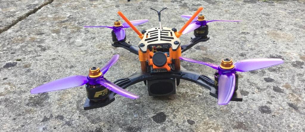
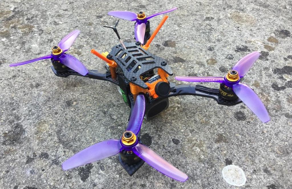
18 Final things Before flying for the first time (and regularly thereafter) test your failsafe (if you don t you will have what is termed a Flyaway at some point where your quad departs like some homesick Mary Poppins and is never seen again. To do this, WITH PROPS OFF, turn on your radio, power up the quad, arm it and give it a little throttle so the motors start spinning, then turn the radio off. Within a second or so the motors should stop dead. Test Hover your quad somewhere safe. Do it Line of Sight, I usually do it in Angle mode and from a safe distance before taking it to the field to fly for the first time. Once you have tested failsafe and test hovered. Make sure everything is screwed down tightly, use blue threadlock on the motor mount screws and the four screws holding the standoffs to the bottom plate. You are now good to fly, please do it safely and legally and ensure you have appropriate insurance such as that provided by BMFA membership. The pictures below show what the build hopefully looks like:
19
Atlatl HV V2. 5.8G FPV Video Transmitter. User Manual & Installation Guide
 Atlatl HV V2 5.8G FPV Video Transmitter User Manual & Installation Guide Contents Overview... 1 Features Specifications Warranty Pinout Diagram and Channel Table... 3 Installation Guide... 4 Functions...
RotorX RX122 Atom Building Guide
 RotorX RX122 Atom Building Guide 1 What s included? 1x Atom CF 2mm Frame 1x Naze32 Flight Controller (Pre- flashed with Cleanflight) 1x pack of mounting hardware 1x JST pigtail 1x servo wire 1x 520tvl
Atlatl FPV Video Transmitter
 Atlatl FPV Video Transmitter User Manual & Installation Guide V1.0 Contents Overview... 1 Features Specifications Warranty Pinout Diagram and Channel Table... 2 Installation Guide... 3 Functions... 6 Channel-Change
R/C Afterburner Light Kit For Electric EDF Jets 2009 Hyperdyne Labs
 R/C Afterburner Light Kit For Electric EDF Jets 2009 Hyperdyne Labs http://www.hyperdynelabs.com Congratulations on purchasing the Afterburner light kit. Your kit is hand assembled in the USA, and we appreciate
User Manual & Setup Guide v1.1
 User Manual & Setup Guide v1.1 Contents Overview... 1 Features Specifications Warranty and Return Policy Spare Parts... 3 Install Betaflight... 4 Install the Receiver... 7 Bind the Receiver... 8 Verify
Getting Started Guide
 Getting Started Guide International edition Rev 1.0 - May 2015 WARNING To use dogs as a good analogy, if the DJI Phantom is a white fluffy Poodle, the Vortex is a Pitt Bull, bred for fighting, and ready
250 Pro Getting Started Guide
 250 Pro Getting Started Guide International edition Rev 1.0 - Dec 2015 Every Vortex 250 Pro is flight tested before leaving the factory. Flight Tested By: WARNING Congratulations on your purchase of one
Manual. HoTT Hornet 250 Tricopter No No C No CAM. Copyright Graupner/SJ GmbH
 EN Manual HoTT Hornet 250 Tricopter No. 16540 No. 16540.C No. 16540.CAM Copyright Graupner/SJ GmbH Index Introduction... 4 Service Centre... 4 Intended use... 5 Package content... 5 Symbols explication...
Quick-Start Guide. Distributed in the UK by: J Perkins Distribution Ltd, Lenham, Kent, UK ME17 2DL.
 Quick-Start Guide Product specifications are subject to change without notice. Due to ongoing development, the actual product may vary from images shown. This product contains chemicals known to the State
TBS UNIFY PRO 5G8 (HV) Video Tx
 Video Tx") TBS UNIFY PRO 5G8 (HV) Video Tx High quality, license-free, ultra-tiny, race ready vtx Revision 2018-03-03 The TBS UNIFY is a new line of video transmitters, optimized for compatibility across multiple
TBS UNIFY PRO 5G8 (HV) Video Tx High quality, license-free, ultra-tiny, race ready vtx Revision 2018-03-03 The TBS UNIFY is a new line of video transmitters, optimized for compatibility across multiple
TBS UNIFY PRO 5G8 (HV) Video Tx
 Video Tx") TBS UNIFY PRO 5G8 (HV) Video Tx High quality, license-free, ultra-tiny, race ready vtx Revision 2017-08-15 The TBS UNIFY is a new line of video transmitters, optimized for compatibility across multiple
TBS UNIFY PRO 5G8 (HV) Video Tx High quality, license-free, ultra-tiny, race ready vtx Revision 2017-08-15 The TBS UNIFY is a new line of video transmitters, optimized for compatibility across multiple
Snail Fence InteleCell Deployment Guide
 Snail Fence InteleCell Deployment Guide Preparation 1. Prepare deployment trip by making sure you have the following materials and tools when you fly up to the site: InteleCell NEMA Enclsoure (grey plastic
NewScope-7A Operating Manual
 2016 SIMMCONN Labs, LLC All rights reserved NewScope-7A Operating Manual Preliminary May 13, 2017 NewScope-7A Operating Manual 1 Introduction... 3 1.1 Kit compatibility... 3 2 Initial Inspection... 3 3
Checklist v05b pag 1
 Sky Rider drone Check list Pre flight checks and tests Tail LED color codes Blue steady -> Radiocontrol is linked to the receiver. Blue flashing -> Headless mode On. Red steady -> Compass is calibrated.
TBS UNIFY PRO 5G8 (HV) Video Tx High quality, license-free, ultra-tiny, race ready vtx
 Video Tx High quality, license-free, ultra-tiny, race ready vtx") TBS UNIFY PRO 5G8 (HV) Video Tx High quality, license-free, ultra-tiny, race ready vtx Revision 2016-10-10 The TBS UNIFY is a new line of video transmitters, optimized for compatibility across multiple
TBS UNIFY PRO 5G8 (HV) Video Tx High quality, license-free, ultra-tiny, race ready vtx Revision 2016-10-10 The TBS UNIFY is a new line of video transmitters, optimized for compatibility across multiple
TBS UNIFY 2G4 500mW / 800mW 16ch Video Tx High quality, long range, micro video transmitter
 TBS UNIFY 2G4 500mW / 800mW 16ch Video Tx High quality, long range, micro video transmitter Revision 2014-07-11 The latest and greatest 2G4 video transmitter from the leaders in long range technology.
Industrial Monitor Update Kit
 Industrial Monitor Update Kit (Bulletin Number 6157) Installation Instructions 2 Table of Contents Table of Contents Industrial Monitor Update Kit... 3 Overview... 3 Part 1 - Initial Preparation... 5 Part
Manual. Race copter alpha 250 Q. No hott. English
 Manual Race copter alpha 250 Q No. 16520.hott English Index Index... 2 Introduction... 3 Service centre... 3 Intended use... 4 Package content... 4 Symbols explication... 5 Safety notes... 5 Preparation
TBS UNIFY PRO 5G8 (HV) Video Tx High quality, license free, ultra tiny, race ready
 Video Tx High quality, license free, ultra tiny, race ready") TBS UNIFY PRO 5G8 (HV) Video Tx High quality, license free, ultra tiny, race ready Revision 2016-03-01 The TBS Unify is a new line of video transmitters, optimized for compatibility across multiple platforms
TBS UNIFY PRO 5G8 (HV) Video Tx High quality, license free, ultra tiny, race ready Revision 2016-03-01 The TBS Unify is a new line of video transmitters, optimized for compatibility across multiple platforms
3M Distribution Box (DDB)
") 3M Distribution Box (DDB) Merged Copper and Fiber Pole/Post Mount Enclosure Installation Instructions November 2015 78-0015-2736-1-A 2 November 2015 78-0015-2736-1-A Contents 1.0 General 2.0 Enclosure
3M Distribution Box (DDB) Merged Copper and Fiber Pole/Post Mount Enclosure Installation Instructions November 2015 78-0015-2736-1-A 2 November 2015 78-0015-2736-1-A Contents 1.0 General 2.0 Enclosure
Instruction Manual for Electronic Blowers and Flashboards
 Instruction Manual for Electronic Blowers and Flashboards These instructions cover both the table model 17212 table top Electronic Bingo Blower (Fig 1) and the 17213 floor model Electronic Bingo Blower
Safety Rules Parts Check Lists and Photos Cable Diagrams for Various Crane Configurations Step by Step Instructions Tips for Packaging and Storage
 EZ CRANE USER MANUAL INCLUDED INSIDE Safety Rules Parts Check Lists and Photos Cable Diagrams for Various Crane Configurations Step by Step Instructions Tips for Packaging and Storage WATCH THE INSTRUCTIONAL
Ten-Tec (865) Service Department:(865)
 Service Department:(865)") Ten-Tec (865) 453-7172 Service Department:(865) 428-0364 Installation Instructions for Ten-Tec Jupiter AT538K Tuner Kit The installation of the AT538K is divided into two steps. The first step is to reprogram
Ten-Tec (865) 453-7172 Service Department:(865) 428-0364 Installation Instructions for Ten-Tec Jupiter AT538K Tuner Kit The installation of the AT538K is divided into two steps. The first step is to reprogram
COLOUR CHANGING USB LAMP KIT
 TEACHING RESOURCES SCHEMES OF WORK DEVELOPING A SPECIFICATION COMPONENT FACTSHEETS HOW TO SOLDER GUIDE SEE AMAZING LIGHTING EFFECTS WITH THIS COLOUR CHANGING USB LAMP KIT Version 2.1 Index of Sheets TEACHING
ipad mini 4 LTE Right Cellular Antenna Replacement
 ipad mini 4 LTE Right Cellular Antenna Replacement Replace the right cellular antenna in an ipad mini 4 LTE. Written By: Evan Noronha ifixit CC BY-NC-SA www.ifixit.com Page 1 of 22 INTRODUCTION Follow
MONO AMPLIFIER KIT ESSENTIAL INFORMATION. Version 2.2 CREATE YOUR OWN SPEAKER DOCK WITH THIS
 ESSENTIAL INFORMATION BUILD INSTRUCTIONS CHECKING YOUR PCB & FAULT-FINDING MECHANICAL DETAILS HOW THE KIT WORKS CREATE YOUR OWN SPEAKER DOCK WITH THIS MONO AMPLIFIER KIT Version 2.2 Build Instructions
Xtreme Power Systems RFU. Installation And Usage Manual. Firmware v1.1. Manual v1.1. Revision Date: June 5 th, 2014
 Xtreme Power Systems RFU (RF Unit for XtremeLink Radio Systems) Installation And Usage Manual Firmware v1.1 Manual v1.1 Revision Date: June 5 th, 2014 All material including, but not limited to photographs,
PowerBook G4 Aluminum 12" GHz LCD panel upgrade
 PowerBook G4 Aluminum 12" 1-1.5 GHz LCD panel upgrade Upgrade a 1400x1050 LCD panel. Written By: martin ifixit CC BY-NC-SA www.ifixit.com Page 1 of 18 INTRODUCTION The original LCD 1024x768 resolution
IPad 3 (glass) REPAIR GUIDE. Version Edition
 REPAIR GUIDE. Version Edition") IPad 3 (glass) REPAIR GUIDE Version 1 2016 Edition IPad 4 REPAIR GUIDE LCD AND DIGITIZER REPLACEMENT RiAna Soto Repair Training Specialist rsoto@cellairis.com FOR EVERY REPAIR MAKE SURE TO COMPLETE, INITIAL,
IPad 3 (glass) REPAIR GUIDE Version 1 2016 Edition IPad 4 REPAIR GUIDE LCD AND DIGITIZER REPLACEMENT RiAna Soto Repair Training Specialist rsoto@cellairis.com FOR EVERY REPAIR MAKE SURE TO COMPLETE, INITIAL,
Safety Information. Camera System. If you back up while looking only at the monitor, you may cause damage or injury. Always back up slowly.
 Table of Contents Introduction...3 Safety Information...4-6 Before Beginning Installation...7 Installation Guide...8 Wiring Camera & Monitor...9-10 Replacement Installation Diagram...11 Clip-On Installation
Assembling and Mounting the Presentation Display, Speakers, Speaker Screens, and Table Door
 CHAPTER 8 Assembling and Mounting the Presentation Display, Speakers, Speaker Screens, and Table Door July 13, 2012, This document provides you with the procedures you perform to assemble and mount the
Manual. HoTT Hornet 250 Tricopter with mz-12 transmitter No RTF. Copyright Graupner/SJ GmbH
 EN Manual HoTT Hornet 250 Tricopter with mz-12 transmitter No. 16540.RTF Copyright Graupner/SJ GmbH Index Introduction... 4 Service Centre... 4 Intended use... 5 Package content... 5 Symbols explication...
UAV Ultimate Atari Video A7800
 UAV Ultimate Atari Video A7800 Basic Install guide because this is really easy mod to do! The UAV is a wonderful piece of tech for what it can do. To summarize, the UAV is a replacement video encoder and
Manual. Alpha 150Q / 170Q / 220Q Quadcopter
 EN Manual Alpha 150Q / 170Q / 220Q Quadcopter 16570.RTF (Racecopter with FPV micro camera and transmitter) 16570.FPV (Racecopter with FPV micro camera) 16570.HoTT (3D copter) 16572.RTF (Racecopter with
Spektrum AirWare Change Log 2016-November-15
 Version 1.06 Spektrum AirWare Change Log 2016-November-15 Changes since 2016-February-05 Special Note In the Telemetry menu, some sensors may not be reported properly on the display or audibly after updating.
TBS UNIFY 5G8 200mW 32ch Video Tx High quality, long range, micro video transmitter
 TBS UNIFY 5G8 200mW 32ch Video Tx High quality, long range, micro video transmitter Revision 2015-07-13 The TBS Unify is a new line of video transmitters, optimized for compatibility across multiple platforms
IPad 4 REPAIR GUIDE. Version Edition
 IPad 4 REPAIR GUIDE Version 1 2016 Edition IPad 4 REPAIR GUIDE LCD AND DIGITIZER REPLACEMENT RiAna Soto Repair Training Specialist rsoto@cellairis.com FOR EVERY REPAIR MAKE SURE TO COMPLETE, INITIAL, AND
Pelican PL-957. Adding additional Tos Link (Digital Optical) inputs, and / or IR Remote
 inputs, and / or IR Remote") Pelican PL-957 Adding additional Tos Link (Digital Optical) inputs, and / or IR Remote Table of Contents: Background;... 2 Section 1: Adding TosLink receivers... 3 Section 2: Adding Remote Capability...
Pelican PL-957 Adding additional Tos Link (Digital Optical) inputs, and / or IR Remote Table of Contents: Background;... 2 Section 1: Adding TosLink receivers... 3 Section 2: Adding Remote Capability...
iosd (On Screen Display)
") iosd (On Screen Display) User Manual V1.4 2012-12-04 www.dji-innovations.com 2012 DJI Innovations. All Rights Reserved. 1 Disclaimer Thank you for purchasing product(s) from DJI Innovations. Please read
iosd (On Screen Display) User Manual V1.4 2012-12-04 www.dji-innovations.com 2012 DJI Innovations. All Rights Reserved. 1 Disclaimer Thank you for purchasing product(s) from DJI Innovations. Please read
TKEY-K16. Touch CW automatic electronic keyer. (No moving parts no contacts) Assembly manual. Last review: March 15, 2018
 Assembly manual. Last review: March 15, 2018") TKEY-K16 Touch CW automatic electronic keyer (No moving parts no contacts) Assembly manual Last review: March 15, 2018 Commands and use manual of the K16 and Updates and news: www.ea3gcy.com Thanks for
TKEY-K16 Touch CW automatic electronic keyer (No moving parts no contacts) Assembly manual Last review: March 15, 2018 Commands and use manual of the K16 and Updates and news: www.ea3gcy.com Thanks for
White Paper. Discone Antenna Design
 White Paper Discone Antenna Design Written by Bill Pretty Highpoint Security Technologies Property of Highpoint Security Technologies Inc The user of this document may use the contents to recreate the
Hubsan Spy Hawk. John Stennard continues his coverage of First Person View flying with a review of a ready to fly camera plane
 Hubsan Spy Hawk John Stennard continues his coverage of First Person View flying with a review of a ready to fly camera plane The Hubsan Spy Hawk is quite a bold attempt to produce a relatively low cost
Fully ly Automaticti. Motorised Satellite t TV System. User s manual REV
 REV. 1.0 Fully ly Automaticti Motorised Satellite t TV System User s manual Customer Help Line: 1300 139 255 Support Email: support@satkingpromax.com.au Website: www.satkingpromax.com.au www.satkingpromax.com.au
Basics of building the ROV Rev2
 Basics of building the ROV Rev2 www.rollette.com/rovrev2 1. Assemble the PVC pipe hull as shown below. All pieces are off the shelf parts. The only parts that need to be cut to length are the 2 pipe. This
Instructions. Cable with Armor F CAUTION. October Rev A
 3M Single Conductor Accessory Breakout Kits (BOK's) for use with 3M Cable Accessories (Terminations, T-Bodies and Push-On Elbows) For Use With Single Conductor Accessories On Three-Core Conductor Cables
VT320X Large Screen Outdoor LCD
 Solutions for Demanding Applications VARTECH S Y S T E M S I N C. Industrial CRT and Flat Panel Displays VT320X Large Screen Outdoor LCD User s Guide Read these instructions completely before attempting
easydelta BUILD MANUAL easydelta 3D printer design & documentation by Achatz Industries Haefland 8A 6441 PA Brunssum The Netherlands
 easydelta BUILD MANUAL easydelta 3D printer design & documentation by Achatz Industries Haefland 8A 6441 PA Brunssum The Netherlands BUILD MANUAL Welcome to the 1. Edition Build Manual for your easydelta
Instruction Manual for the & Electronic Bingo Blower
 Instruction Manual for the 17212 & 17214 Electronic Bingo Blower The directions in this manual when referring to the 17212 are referring to software version 2.83 (you can find what version your blower
Cable System Installation Guide
 Overview Cable System Installation Guide 5/19/2008 Our recommended approach for the installation of your Circle Graphics Cable Systems on the panels in your market is to install the fixed hardware (namely
PEM1124ENG ENGLISH. STK TERMINATION KIT FOR PLASTIC CABLE WITHOUT ARMOURING 1 kv STKR TERMINATION KIT FOR PLASTIC CABLE WITH ARMOURING 1 kv
 INSTALLATION INSTRUCTION PEM1124ENG 2010-05 STK TERMINATION KIT FOR PLASTIC CABLE WITHOUT ARMOURING 1 kv STKR TERMINATION KIT FOR PLASTIC CABLE WITH ARMOURING 1 kv ENGLISH 4 CORE 3+1 CORE 2/8 PEM1124ENG
Bill of Materials: Magic Color PART NO
 Magic Color PART NO. 2193838 Magic color is a guessing game. With this game you can surprise your friends and leave them with amazement, how the game guesses what they have in their minds. Only two selections
iphone 7 Plus LCD Screen and Digitizer Replacement
 iphone 7 Plus LCD Screen and Digitizer Replacement Replace just the bare front panel not including the home/touch ID sensor, front-facing camera and sensor cable, or earpiece speaker in an iphone 7 Plus.
M1, M2GO and M2PC MIDI PCB Module Installation Guide SMPTE PCB Module Installation Guide
 M1, M2GO and M2PC MIDI PCB Module Installation Guide SMPTE PCB Module Installation Guide Author Part number Date Matthias Hinrichs/Chris Foblets 35000620-B 20.06.2012 This guide is also available for download
3M Cold Shrink QS4 Integrated Splice Kit QS4-15JCN
 3M Cold Shrink QS4 Integrated Splice Kit QS4-15JCN-500-1000 for Jacketed Concentric Neutral (JCN) and Flat Strap Neutral Cable Instructions IEEE Std. 404 15 kv Class 150 kv BIL F CAUTION Working around
3M Cold Shrink QS-III Silicone Rubber Splice Kit 5488A-TOW/WOT
 3M Cold Shrink QS-III Silicone Rubber Splice Kit 5488A-TOW/WOT For Tape Over Wire (TOW) and Wire-Over-Tape (WOT) Shielded Cable For 250 2000 kcmil cable with 650-mil primary insulation thickness Instructions
TeamWork Installation Guide
 C G G 00-0V/ A MAX TX RX +V APARATUS US 0 TeamWork Installation Guide TeamWork TeamWork is a fully customizable collaboration system comprised of an switcher, Show Me cables, a control processor, and a
Commissioning Guide. firepickdelta. Commissioning Guide. Written By: Neil Jansen firepickdelta.dozuki.com Page 1 of 22
 firepickdelta Commissioning Guide Written By: Neil Jansen 2017 firepickdelta.dozuki.com Page 1 of 22 Step 1 Pre-Requisites Before commissioning, please make sure ALL of the following steps have been completed,
PEM1126ENG ENGLISH STPKR. TERMINATION KIT FOR PAPER CABLE WITH LEAD SHEATH 1 kv INSTALLATION INSTRUCTION
 INSTALLATION INSTRUCTION PEM1126ENG 2010-05 TERMINATION KIT FOR PAPER CABLE WITH LEAD SHEATH 1 kv ENGLISH 2/6 PEM1126ENG 2010-05 GENERAL INFORMATION - Check that the kit is suitable for the cable type.
Toughsat Flyaway Users Manual
 Toughsat Flyaway Users Manual TOUGHSAT FLYAWAY USERS MANUAL V.1.6 September 2012 Important warning regarding your TOUGHSAT System All power to the system (controller, modem, external network devices) MUST
SA Development Tech LLC Press Counter II 1.00
 SA Development Tech LLC Press Counter II 1.00 Manual Unit is a compact and convenient 2 x 2 Disclaimer: Many things can go wrong during the reloading process and it is entirely your responsibility to load
Obtained from Omarshauntedtrail.com
 http://www.cindybob.com/halloween/ledlighting/ledspotlights/ Introduction In our 2005 haunt providing 120V AC power to the various lights and props requiring it became a fairly large problem. Extension
4125 system setup and deployment quick start guide
 4125 system setup and deployment quick start guide OPERATION IN AIR Do not operate the system while the tow fish in air for extended periods. The system may be enabled to transmit while in air for test
3M Cold Shrink Splice Kit QS-III 5514A
 3M Cold Shrink Splice Kit QS-III 5514A for UniShield, Wire Shielded, Longitudinally Corrugated (LC), and Tape Shielded (Ribbon Shielded) Cable or Transitions to Concentric Neutral (CN)/Jacketed Concentric
Multi-Key v2.4 Multi-Function Amplifier Keying Interface
 Multi-Key v2.4 Multi-Function Amplifier Keying Interface ASSEMBLY & OPERATION INSTRUCTIONS INTRODUCTION The Harbach Electronics, LLC Multi-Key is a multi-function external device designed for the safe
DIY. How to install a PL-259 connector. Parts list: Tools list: Worthwhile projects you can build on your own
 DIY Worthwhile projects you can build on your own Just like you, I often need to install a PL-259 connector on a length of coax (coaxial cable), to attach it to the mating SO-239 connector of a mobile
Introduction 1. Green status LED, controlled by output signal ST
 Introduction 1 Welcome to the magical world of GENIE! The project board is ideal when you want to add intelligence to other design or electronics projects. Simply wire up your inputs and outputs and away
Introduction 1. Digital inputs D6 and D7. Battery connects here (red wire to +V, black wire to 0V )
") Introduction 1 Welcome to the magical world of GENIE! The project board is ideal when you want to add intelligence to other design or electronics projects. Simply wire up your inputs and outputs and away
Introduction 1 Welcome to the magical world of GENIE! The project board is ideal when you want to add intelligence to other design or electronics projects. Simply wire up your inputs and outputs and away
Panzer 3.0 Assembly Instructions & Checklist
 Panzer 3.0 Assembly Instructions & Checklist Parts Included & Preparation Legend A. 5x Silver M4 Aluminum Screws B. 4x 10-24 Screws C. 8x 4-40 Pan head Screws D. 2x 4-40 Flat head Screws E. 2x 4-40 Nuts
A6 OPERATING INSTRUCTIONS
 Amerec s A6 control for the AX steamer is a touch screen control intended to be mounted on a wall, generally in or near the steam bath. It may be mounted directly on the wall surface or, using an optional
MyFlyDream TeleFlyPro V1.04
 MyFlyDream TeleFlyPro V1.04 www.myflydream.com Notes Thank you for purchasing the MyFlyDream TeleFlyPro (hereinafter referred to as TFPro). Please follow this manual to get familiar with the TFPro and
Complete Train Control. Run Your Trains, Not Your Track!
 DH166PS Fits Many DCC-Ready HO Locomotives.672 x 1.074 x.259 17.08mm x 27.28mm x 6.6mm Features: FX3 Function outputs for prototypical lighting effects and on/off control: Digitrax Complete Train Control
TV Lift System Model CL-65 Installation Instructions
 TV Lift System Model CL-65 Installation Instructions Contact: Support@Nexus21.com Toll Free: (866) 500-5438 Phone: (480) 951-6885 Fax: (480) 951-6879 Revised: 01/17/17 Below is a parts list describing
Aruba Outdoor AP Antenna Weatherproofing
 Aruba Outdoor AP Antenna Weatherproofing Installation Guide Installing Antennas 1. Before connecting the antennas, identify which of your antennas are 2.4 GHz and which are 5 GHz. 2. After identifying
2178 Fiber Optic Splice Case and 2181 Cable Addition Kit
 2178 Fiber Optic Splice Case and 2181 Cable Addition Kit Instructions January 1994 Issue 1, 34-7029-6387-6 1 2 Contents: 1.0 General... 4 2.0 Specifications... 4 3.0 Kit Contents... 5 SECTION 1: 2178 Splice
QUICK INSTALLATION GUIDE
 V1.1.1/2018 homeit.io All rights reserved Index NR. CHAPTER PAGE 1 Introduction 2 1.1 The homeit System 2 2 Equipment and materials 3 2.1 The homeit KIT 3 2.2 Tools & Supplies 4 3 Location of the homeit
Website: Tel: ADDRESS: 6475 Las Positas Rd. Livermore, CA Item No. E5B/E5S Installation Guide
 Website: www.flexispot.com Tel: -855-4-808 ADDRESS: 6475 Las Positas Rd. Livermore, CA 9455 Item No. E5B/E5S Installation Guide Specifications Step Column 3 Max. Weight Capacity 0 Ibs (00 kg) Speed 38mm/s
Cable ISOBUS Active Termination
 ISOBUS Retrofit Kit Ag Leader Technology Note: Indented items indicate parts included in an assembly listed above Part Name/Description Part Number Quantity ISOBUS Retrofit Kit 4100843 1 Hex Head Bolt
USER MANUEL. SNIPE 2 Ref R13
 USER MANUEL SNIPE 2 Ref. 0141317R13 Contents 1. General Information 1-1. Introduction 1-2. Proper use and operation 1-3. Safety notes......... 2 3 3 2. Contents 2-1. Accessory included 2-2. Name of parts......
Tube Cricket Build Guide
 Tube Cricket Build Guide The Tube Cricket is a small-wattage amp that puts out about 1 watt of audio power. With a 12AU7 tube-preamp and a JRC386 power amp, the Tube Cricket gives you great tone in a compact
3M Cold Shrink Splice Kit QS-III 5515A
 3M Cold Shrink Splice Kit QS-III 5515A for UniShield, Wire Shielded, Longitudinally Corrugated (LC), and Tape Shielded (Ribbon Shielded) Cable or Transitions to Concentric Neutral (CN)/Jacketed Concentric
How To Build Megavolt s Small Buffered JTAG v1.2
 How To Build Megavolt s Small Buffered JTAG v1.2 Abstract A JTAG cable should be considered mandatory equipment for any serious tester. It provides a means to backup the information in the receiver and
PC-250. SMD Taped Parts Counter Operator s Manual. ISO 9001:2008 Certified. V-TEK, Incorporated 751 Summit Avenue Mankato, MN USA
 PC-250 SMD Taped Parts Counter Operator s Manual ISO 9001:2008 Certified V-TEK, Incorporated 751 Summit Avenue Mankato, MN 56001 USA (P) 507-387-2039 (F) 507-387-2257 www.vtekusa.com Dear Customer: All
1. Unlocking your FT847 to get 4m ( for those who already have unlocked one, please move to chapter 2).
.") Modification Yaesu FT-847 dla pasma 70MHz Part II practical solution v. 1.0 (Oct 2013) Greg SP3RNZ sp3rnz@wp.pl PA mod idea by Marc PA1O TX/RX mod idea by Hellar ES1II/8 This article describing how to
Modification Yaesu FT-847 dla pasma 70MHz Part II practical solution v. 1.0 (Oct 2013) Greg SP3RNZ sp3rnz@wp.pl PA mod idea by Marc PA1O TX/RX mod idea by Hellar ES1II/8 This article describing how to
research platform comma.ai, github.com/commaai/neo
 neo research platform comma.ai github.com/commaai/neo 1 suppliers 2 electronics 1. download digikey.csv 2. go to digikey.com/classic/ordering and register or log in 3. click and navigate to the downloaded
150 Mini Instruction manual International edition
 150 Mini Instruction manual International edition Rev 1.1 - July 2016 Thank You! The team that designed the Vortex Mini would like to thank you for purchasing this product. Many hours of development, and
Hip Hop Activity Box. Instruction Manual. Hip Hop Activity Box 22875, October 2018 Copyright ROMPA Ltd
 Hip Hop Activity Box Instruction Manual Hip Hop Activity Box 22875, October 2018 Copyright ROMPA Ltd Contents 3 Panel Overview 5 Colour 5 Description 5 Technical Specification 6 Dimensions 7 Contents 8
Caution. Hanging the Screen:
 Installation Instructions for Laminar and Laminar XL Projection Screens Caution 1. Read Instructions through completely before proceeding; keep them for future reference. Follow these instructions carefully.
ConnectAnywhere Prep Kit OEM INSTALLATION MANUAL
 Connectnywhere Prep Kit OEM INSTLLTION MNUL TBLE OF CONTENTS Introduction 2 Safety 2 Resources Required 3 Preparation 3 Installation 3 Notes 9 Introduction This document provides instructions for the installation
E4200 Antenna Installation Instructions: 1. Soldering required (here is the list of tools you will need)
") Thank you for purchasing the 6 Antenna Mod Kit for your Linksys router. First we will show you how to install the antennas for your router. Next we will teach you how to setup the DD-WRT firmware which
Thank you for purchasing the 6 Antenna Mod Kit for your Linksys router. First we will show you how to install the antennas for your router. Next we will teach you how to setup the DD-WRT firmware which
3M Cold Shrink QS4 Integrated Splice Kit QS4-35TS
 3M Cold Shrink QS4 Integrated Splice Kit QS4-35TS-350-1000 for Tape Shield, Wire Shield, UniShield, and Longitudinally Corrugated (LC) Cable Instructions IEEE Std. 404 35 kv Class 250 kv BIL F CAUTION
RADIO FREQUENCY SYSTEMS
 RADIO FREQUENCY SYSTEMS Optimizer RT FAQ s Q. What information is require before running the software? The Serial Number of each ACU MUST be recorded with the Model number of the antenna that it is attached
Installation Guide. NEC InfinityBoard 65 & 84
 Installation Guide NEC InfinityBoard 65 & 84 Table of Contents Please be aware. This manual is a supplement to the monitor s manufacturer instruction. It can not be treated as a separate document. Please
Motor Operated Solar Shade with Valance Installation and Care Instructions Complete Video Instructions Available Online at
 * Motor Operated Solar Shade with Valance Installation and Care Instructions Complete Video Instructions Available Online at www.keystonefabrics.com Step 1: Identify the parts of your shade (parts shown
ipad Air 2 Wi-Fi Display Assembly Replacement
 ipad Air 2 Wi-Fi Display Assembly Replacement Fix a cracked or faulty screen by replacing the display assembly in an ipad Air 2 Wi-Fi. Written By: Evan Noronha ifixit CC BY-NC-SA www.ifixit.com Page 1
Installation instructions, accessories. Subwoofer. Volvo Car Corporation Gothenburg, Sweden. Page 1 / 29
 Installation instructions, accessories Instruction No 30752136 Version 1.1 Part. No. 30752135 Subwoofer Volvo Car Corporation Subwoofer- 30752136 - V1.1 Page 1 / 29 Equipment A0000162 A0000161 A0801178
Setup Guide. Read me BefoRe unpacking!
 Setup Guide Read me BefoRe unpacking! Package Contents In The Replicator package The Replicator SD card (in The Replicator SD card slot) In the Accessory Box found within The Replicator frame Single or
GENUINE PARTS CAUTION
 GENUINE PARTS SATELLITE RADIO INSTALLATION INSTRUCTIONS 1. DESCRIPTION: SATELLITE RADIO SYSTEM 2. PART NUMBERS: XM tuner kit 999U9-NV003 XM antenna kit 999U9-VR000 Sirius tuner kit 999U9-NV004 Sirius antenna
SIR-GM1 GM CLASS-2 BUS COMPATIBLE SIRIUS SATELLITE RADIO TUNER
 SIR-GM1 GM CLASS-2 BUS COMPATIBLE SIRIUS SATELLITE RADIO TUNER Installation Guide Congratulations on your purchase of the SIR-GM1 the GM Compatible SIRIUS Satellite Radio Tuner! Your SIR-GM1 is designed
3M Motor Lead Inline Splice 5331, 5332, 5333 & 5334
 3M Motor Lead Inline Splice 5331, 5332, 5333 & 5334 for 5/8 kv Non-Shielded and Shielded Cables (Ribbon, Wire and UniShield Cables) Instructions Cable Size Range: Feeder: #8 AWG 500 kcmil Motor Lead: #10
Building the BX24-AHT
 Building the BX24-AHT file:///f /LASER/build-it.htm (1 of 8) [03/04/2002 5:21:52 PM] file:///f /LASER/build-it.htm (2 of 8) [03/04/2002 5:21:52 PM] Tips & Tricks Use a 25W or smaller soldering iron with