5 th Modulator Klystron Workshop MDK2001. Session 1-2 Chairman : G. Caryotakis (SLAC) Klystron Technology
|
|
|
- Raymond Skinner
- 5 years ago
- Views:
Transcription
1 5 th Modulator Klystron Workshop MDK2001 Session 1-2 Chairman : G. Caryotakis (SLAC) Klystron Technology
2 REVIEW OF SESSION 1.2 KLYSTRON TECHNOLOGY G. Caryotakis (Chairman) SLAC These were 4 completely different papers with essentially nothing in common except that all devices were designed or built to power accelerators. To summarize: 1. The CPI paper (Ed. Eisen) CPI is developing klystrons for SNS at 805 MHz. Ed discussed the experimental performance of the high power tube (2.5 MW peak, 250 kw average) and the predicted performance of a lower power tube (550 kw peak, 8% duty cycle) for superconducting cavities. These are pretty straightforward klystrons, with good efficiency. The design (single beam, ordinary cavities) is optimised for the frequency and power. 2. The TMD Technologies paper (Graham Phillips) This is a paper tube, so far, but a design that will probably be successful. The problem is getting a very wide bandwidth (10%) at a relatively low power (500 kw) at L-band. At 100 kw and a microperveance of about 2, and 30% efficiency the beam impedance is about 2500 ohms. If one assumes a required gap impedance of perhaps 3000 ohms and an R/Q of 120 in a single cavity, then the Qext would be about 25, which would only produce a half-power band width of 4%. The fact that an overlapping mode (0-π), 2-gap output cavity was used and the 10% bandwidth obtained, is quite impressive. 3. The THALES paper (Armel Beunas) This is the first MBK built and delivered to a customer in the Western world. It is assumed that the reasons for the 7 beams are both lower the voltage and increased cooling surfaces, in addition to higher efficiency at lower perveance, (which is the main reason). The tube appears quite uncomplicated despite the seven cathodes and drift tubes. If a single beam tube had been attempted, instead of an MBK, and if a comparable efficiency was desired, then a klystron with µk = 1 and an efficiency of 50% would have a beam voltage of 210 kv, instead of 117 kv. The tube would have also been much longer. 4. The SLAC paper (George Caryotakis) This is perhaps the first fully simulated sheet beam klystron. It uses 2 sheet beams ( with a 10:1 aspect ratio) to produce 150 MW peak, and 50 kw average power, at 11.4 GHz. Simulations performed so far suggest that the beam and circuit will be stable, the efficiency is high, and parts count very low, hence a low cost source for the NLC which requires over a 1000 klystrons at half that power. We believe that a DSBK klystron at 30 GHz (for CLIC) could be designed to produce 50 MW at good efficiency (> 50%).
3 A SHEET-BEAM KLYSTRON PAPER DESIGN G. Caryotakis Stanford Linear Accelerator Center Abstract What may be the first detailed cold test and computer simulation analysis of a Double Sheet Beam Klystron (DSBK) was performed at SLAC. The device was conceptually designed mechanically, and evaluated electrically for beam formation, gain, stability and efficiency. It is believed that the DSBK can be built at a relatively low cost for a future NLC collider and can produce at least 150 MW at 11.4 GHz with PPM focusing. Voltage and current are 450 kv and 640 A, respectively. The Sheet Beam Klystron (SBK) is a device that has been considered as a microwave source for at least 60 years, but has never been fully designed or constructed. It was first proposed by Kovalenko in Russia in 1938 and revisited repeatedly over the years in the USSR, France and the US. The fact that no serious attempt was ever made to build and test an SBK can probably be attributed to the existence of alternatives and to perceived electrical and mechanical difficulties. The principal electrical difficulties have been the large drift tube and overmoded cavities that the SBK requires. Also, designers have been concerned with the possibility that the sheet beam might be unstable suffering from diocotron break-up, or be difficult to contain laterally at the edges. Mechanical issues centered mostly at the gun, and the thermal design of a large cathode/heater package. Certainly, the construction of sheet-beam guns is beyond the capabilities of most universities and national laboratories. Industry, for the most part, has not taken on the SBK design problem, simply because other klystron types could serve existing requirements, or could be easily developed. The chief virtue of the SBK is that its large lateral dimensions permit high power to be attained with low current densities in the cathode, and low power concentration in the cavities. This is the same advantage that multiple beam klystrons have over single-beam klystrons. The difference is that an SBK can be made with a fraction of the parts an MBK requires, or for that matter, that are normally used in an ordinary klystron. At SLAC, the logistics of the Next Linear Collider (NLC) initially required several thousand 75-MW X-band klystrons for the 500 GeV versions of the machine. Gradually, as these tubes were built, put to use, and accumulated hours, confidence in their performance led to increases in the pulse length and the ratio of pulse compression. Today, the baseline NLC klystron has a pulse length of approximately 3 microseconds and the number of PPM-focused klystrons is approximately Obviously, this is still a large number of fairly complicated tubes. A klystron with twice the output would be very desirable, especially if a 1-TeV NLC were to be considered. However, 150 MW peak and a 50 kw average power at 11.4 GHz is uncomfortably high with a single beam and an output circuit with a one-centimeter bore. This is what motivated us to look very seriously into the SBK. Through a process of parameter trade-offs, the design that has emerged employs two beams, each with an aspect ratio of 10:1 and perveance of 1.1 x 10⁻⁶ (0.11 micropervs per square). These are conservative numbers, and they are, in part, dictated by the necessity to use periodic focusing and to place magnets and polepieces at some distance from the beams in order to simplify the mechanical design and allow water-cooling in the space between the circuit and the magnet stack.
 slabs of copper.")

4 As a matter of fact, mechanical considerations formed the basis for the overall design of this DSBK (Double Sheet Beam Klystron). Referring to Figs. 1 and 2, it can be seen that the cavities, drift tunnels and collectors are fabricated on numerically controlled machines out of four (4) slabs of copper. The two klystrons making up the DSBK share the same vacuum plenum at the double gun, but are otherwise separate mechanically and electrically. The two halves of each klystron are separated by a fraction of a millimeter so that cavities and drift tubes can be pumped from vacuum manifolds running along the entire length of the rf sections and the collectors. This is possible because the TM modes in the cavities do not have rf currents crossing the surface where the two halves are separated. (The guns are shown gridded because the picture was drawn for a different version of the DSBK). Fig. 1 Fig. 2

5 These are twin 5-cavity klystrons, with all cavities of the extended type operating in the - mode. The paper design consisted of a number of simulations and some cold testing. We wished to verify the following go, no-go conditions: 1. A gun can be designed with the necessary convergence and a low cathode current density. 2. The beam is well behaved and does not spread excessively laterally. 3. Cavities with sufficiently good R/Q and coupling coefficient can be designed, and provide a reasonably uniform field across the beam. 4. The klystron has good gain and efficiency. 5. The cavities are free of monotron oscillations for TM modes. These were the conditions that had to be satisfied before prototype construction is attempted. Results are shown in the figures that follow. Fig Figure 3 shows a MAGIC 3D simulation of a gun which provides a beam 8-mm thick, 8-cm wide, with a beam current density of 50 A/cm 2, and an area convergence of 10, i.e. a cathode current density of 5 A/cm 2. The cathode surface is elliptical for good optics. 2. Lateral gun electrodes have not been designed as yet, but Fig. 4 shows that a beam artificially injected in the drift tunnel and immersed in a 3000 magnetic field is not spreading in a 10-cm distance and remains evenly distributed along its width. PPM simulations have not been performed as of yet, but PPM focusing is not expected to be a problem. 3. The cavities for the DSBK were at first designed as single cutoff waveguides. This is the method proposed at SLAC more than 15 years ago for providing a flat electric field across the width of the beam. A cold test model was constructed to test this scheme, as well as the isolation between cavities separated by varying lengths of a 1.2 x 9 cm drift tunnel (Fig.5) Cavity isolation was found to be more than 50 db in 5 cm of drift tube. However, GdfidL and MAGIC calculations showed that the coupling coefficient and R/Q were too low for a single cavity of the cutoff waveguide type. Figure 6 shows that the coupling coefficient for a transit angle of about 1 radian was only Using triplet cutoff waveguides coupled capacitively
 are a printer artifact. Fig. 4 4. With two of these cavities and an artificial beam, a MAGIC calculation produced a gain of about 18 db between two triplets spaced about 30 cm apart.")

6 through the drift tube and operating in the mode corrected this. The coupling coefficient increased to 0.36 with an R/Q of 52 ohms. The light spots in the middle of the top view of the beam (Fig. 4) are a printer artifact. Fig With two of these cavities and an artificial beam, a MAGIC calculation produced a gain of about 18 db between two triplets spaced about 30 cm apart. Figure 7 shows the ratio of the rf current induced in the second cavity to the artificial rf current in the beam exciting the first cavity. We have inferred from these simulations the reduced plasma wavelength and beam loading parameters necessary to calculate small-signal gain. Using these in a standard gain vs. frequency calculation, we predict a 68+ db gain for the 5-cavity tube (Fig. 8 is on a separate page). Finally, a large-signal 3D-MAGIC simulation (Fig. 9) was run in which a beam modulated with an I 1 /I 0 of 1 drives a triplet. The figure shows normal debunching, and Figure 10 indicates that this is evenly distributed across the width of the beam. A simulation for a higher value of I 1 /Io will follow. Fig. 5
7 Single Cavity M = Ez 1.5E E E E+00 Ez Ez*Cosine Integral{Ez*dz} Integral{Ez*Cosine*dz} SBK Field Profile 4.5E E E E+00 Integral{Ez.dz} -5.0E E E E Z Triple Cavity M = Ez Ez*Cosine Integral{ Ez *dz} Integral{Ez*Cosine*dz} SBK Field Profile Ez Integral{Ez.dz} Z Fig. 6 Fig. 7. RF current vs. Z.

8 Fig. 9 Fig. 10
9 a b Io 320 f w 0.08 Brillouin field Data Inputs GPSDRV02.MCD Vo Beam Voltage (V) γ a = Beam resistance Plasma Frequency (rad/s) One-half of an 11.4 GHz 150-MW DSBK (Coupling coefficient from GdfidL, beam loading, reduced plasma frequency from MAGIC) Beam Current (A) Center Frequency (GHz) Drift tunnel half-height (meters) Beam half-thickness (meters) Beam width (meters) γ b = Ro = Bbr = Gauss ohms ωp = Vo Ro := Io Gun Microperveance (ua/v^1.5) Beam current dens. A/cm^2 Electron Prop. Constant (rad/m) Radial propagation constant (rad/m) γ = Bunching wave number (rad/m) Gap transit angle 100 No of cavities: Jo = 50 K = 1.06 βe = βq = βe d 1 = N 5 GAIN (DB) vs FREQUENCY PPmax P3 2 γ a S := b b = S = 1.5 R π f ωq = log( P s ) fo s λq = meters λp = meters Power 50% total efficiency: 0.5 Vo Io 10 9 = Cavity Rs/Q External Q and Qo GW Cavity Frequency (GHz) Gain Gap-Gap L (m) PPmax= Db RQ Qe Qo f l RQ Qe Qo f l RQ Qe Qo f l RQ Qe 4 Qo f l RQ Qe Qo f l Data Output Beam loaded Q Gap Distance Coupling Coefficient Drift Length (m) (induced current) (degrees) Qb Zg 1 = 0 M 1 = βql 1 = 0 Qb Zg 2 = 0.1 M 2 = βql 2 = Qb Zg 3 = 0.2 M 3 = βql 3 = Qb Zg 4 = 0.3 M 4 = βql 4 = Qb Zg 5 = 0.4 Fig. 8 M 5 = βql 5 =
10 7 Mode Number for Beam Width N=4, +++ mode "+ + +" "+ 0 -" "+ - +" Frequency [GHz] N "+ + +" "+ 0 -" "+ - +" Fig To test for stability in unloaded triplet cavities, a mode search was conducted using MAGIC (Fig. 11), and several of the TM modes were tested for negative beam loading, using GdfidL and the M 2 minus Mplus 2 criterion, the difference between the squares of the coupling coefficients for the fast and the slow space charge waves. (See Fig. 12). The slight differences in the frequencies between Fig. 12 and mode search and the stability tests in Fig. 12, are due to the fact that the structure used in Fig. 12, was tuned at GHz, instead of GHz.
11 Beam Coupling pi-mode βe. 2 Mminus i i 8. βq Mplus i Vb i mode N=0 and 2, and βe. 2 Mminus i i 8. βq Mplus i Vb i +++ mode N=4, βe. 2 Mminus i i 8. βq Mplus i Vb i Fig. 12 Stability test examples
12 CONCLUSIONS Although additional simulations will be necessary, it is clear the device has an excellent chance to work and should be built. This may take place in 2002.

13 APPENDIX 1 LATE BREAKING RESULTS FROM MRC Some recent results arrived from MRC which were too late to incorporate into the body of the paper, but too important to leave out. The first transmission from Dave Smithe of MRC, who was asked to drive a triplet cavity with a fully pre-bunched beam, is reproduced here without comment except to note that this is the first effort to run the simulation for full power. No attempts have been made to tune or otherwise adjust for maximum power. A.1.1 OUTPUT POWER Geometry: Resistive load filling each of the end cells. Beam voltage = 450 kv, Beam current = 320 amps, I 1 /I 0 = 1.8. Output Power: 62.0 MWatts, Wall Losses: 5.5 MWatts A top view of the cavity geometry is shown in Fig. A There is resistive load in each of the end cells. Fig. A A pre-bunched beam is injected into the cavity, and it is rung up to saturation. Many runs were done to optimize the output power by varying the amount of resistance (cavity Q), and hot-test frequency-shift (+0.01%). The following figure (A.1.1.2) shows the time-history of cavity saturation. The first plot shows the sum of power to the end-cell load plus wall-losses, and the second plot shows just wall-losses. Load + Wall Losses Just Wall Losses Fig. A.1.1.2


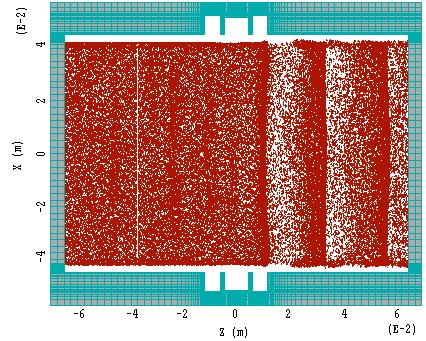
14 A view of the particles and current is shown below (Fig. A.1.1.3). The shape of the pre-bunched current is a sine wave, truncated below some value, and re-scaled to give the correct DC current. The particles are injected at a single energy of 450 kv. Fig. A.1.1.3

15 Shown below are views of particle-energy, average-energy-per-particle, and RF-current, down the length of the drift tube (Fig. A.1.1.4). Note that few, if any, particles are turned-around. About 47% of the original beam energy is lost, 43% to the output load, and 4% to copper wall losses. The RF current at the exit is about _ of the original pre-bunched RF current. Particle Energy Average Particle Energy RF Currrent Fig. A.1.1.4


16 A.1.2 TEST OF CAVITY STABILITY This is a final transmission from MRC (Fig. A.1.2.1). The objective here was to completely unbalance the beam to see whether modes might be excited in the cavity that would lead to oscillations. It can be seen from the treatment below that this did not happen. Geometry: Unloaded, copper cavity. Used _ of beam, e.g., missing right and lower halves, with no RF signal, other than the initial transient. The offset beam and the initial transient provide the seed for any unstable modes. The beam current density is the save as for the previous 450 kv, 320 amp runs. Fig. A.1.2.1
17 From previous simulations, it is already known that the system is stable at the operating mode, as the operating mode has been to seen to saturate in a conventional manner during small-signal analysis. The simulation was run for 80 nanoseconds. Any linear instability would exhibit an exponential increase in the electromagnetic energy (U em = _ε E 2 + _µ H 2 ) stored within the cavity, as the instability mode grew in amplitude. No such increase was observed. The offset beam, in both X and Y directions, should couple strongly to virtually all conceivable modes, thus there is little chance that an instability exists, but is undetected, since the instability seed is quite strong. Wall losses of copper have been included. Thus it is still possible that a perfectly conducting cavity might experience an instability, but that the copper wall-loss loaded system is stable. Instead of an exponential rise in EM energy, a very slow, approximately linear, growth in electromagnetic energy was observed (Fig. A.1.2.2). This is typical of all unfiltered relativistic particle-in-cell simulations and is associated with growth of short-wavelength (grid-size) particle noise in a simulation. There is no identifiable cavity mode structure associated with particle noise (Fig. A.1.2.3). EM Energy in Cavity Fig. A There is also no evidence of a coherent RF signal on the particle positions or energy after 80 nanoseconds.


18 Fig. A This result is for a single cavity. Instability associated with power propagation between two or more triple-cavities separated by rectangular drift tube has not been investigated here.
19 ACKNOWLEDGEMENTS Thanks are due to Daryl Sprehn, who developed the gun optics, Mike Neubauer for the GdifdL simulations, David Smithe of MRC who performed the MAGIC simulations, and Randy Fowkes for the cold test work.
20 A HIGH POWER LONG PULSE HIGH EFFICIENCY MULTI BEAM KLYSTRON A.Beunas and G. Faillon Thales Electron Devices, Vélizy, France S. Choroba DESY, Hamburg, Germany Abstract THALES ELECTRON DEVICES has developed and built a new high power - long pulse - high efficiency - multi beam klystron (MBK), the TH1801. This MBK uses 7 low perveance beams in parallel and is in operation at the TESLA TEST FACILITY at DESY, where it was tested at full pulse duration of 1.5ms. It reached 10MW at 117kV and 131A with an efficiency of 65%. This paper reports on the tube and the test results obtained on the TH1801 multi beam klystrons built up to now. 1. INTRODUCTION In the field of long pulse high power tubes, new challenges have to be taken up to go further in the increase of peak power, efficiency and reliability. This boost of performance is requested to minimize the investment and the operation costs of the entire RF system of a particle accelerator. The peak power delivered by a long pulse single beam klystron is limited by the high voltage its gun can withstand. For instance, the regular L-band TH2104C klystron delivers 5MW peak at 2ms pulse duration. It operates at a voltage of 128kV and a current of 88A. The efficiency is 44%, in agreement with a beam perveance close to the maximum practical value of A/V 1.5. To increase the current and then the power, a solution is to use several low perveance beams in parallel within the same vacuum envelope[1,2]. The advantage of this solution is the lower voltage required and the higher efficiency compared to the single beam klystron. This multi beam concept, which is not a new one, has been applied on the tube THALES ELECTRON DEVICES has developed for the TESLA TEST FACILITY (TTF), the 10MW 1300MHz 1.5ms high efficiency multi be am klystron TH1801 (see photograph in figure 1). About MW TH2104C would be required to power the TESLA linear collider. Thanks to the multi beam klystron, the number of RF source is two times smaller, without increasing the high voltage and with an efficiency yield of about 20 points. 2. DESIGN ASPECTS 2.1 Main design parameters The main design parameters are discussed in the following paragraphs and are summarized in table 1. This MBK uses 7 low perveance parallel beams which propagate in 7 drift tubes and which interact with the electric field of the common cavities they travel through. The effective perveance of the MBK is A/V 1.5 at the design voltage of 110 kv, with each single beam perveance being A/V 1.5, that is to say 18.2A per beam. This low single beam perveance, with low space charge forces enables strong beam bunching and consequently high efficiency.

21 According to the empirical relation η= κ(µperv) (1), an efficiency of 70% is achievable with a perveance Κ= A/V 1.5. Table 1 Design parameters of the TH1801 Fig. 1 The TH1801 multi beam klystron 2.2 Interaction section The interaction structure has been optimized to maximize the degree of bunching and to ensure stable operation on a mismatch of 1.2:1 at any phase. This klystron is a 6 cavities design with four intermediate cavities inductively tuned, all operating on fundamental mode TM010. The simulations were carried out on one of the seven beams with an harmonic disk 1D code, and assuming that the R/Q factor is Nb (number of beams) times the R/Q factor related to a single beam. As a high efficiency operation leads to the creation of slow electrons, and in order to inhibit possible oscillations, particular attention was paid to avoid reflected electrons in the output gap and at the entrance of the collector. Related to the load, the output cavity has been slightly over coupled, so that the klystron can operate with a good stability on a mismatched load, under optimum phase condition. In addition to the large overall perveance, this results in an unusual low value of external Qx, about Beams generation Operating frequency 1300 MHz Output peak power 10 MW Output average power 150 kw RF pulse duration 1.5 ms Frequency repetition 10 Hz Number of beams Nb 7 Cathode voltage, max. 115 kv Total beam current 130 A Total perveance A.V -1.5 Efficiency 70 % (VSWR=1.2:1 optimized phase) Gain (saturated), min 47 db Bandwidth (-1dB) 3 MHz Number of cavities 6 RF input N type RF output 2xWR650 Cathode loading, max. 5.5 A/cm² Beam area convergence 9:1 Electric field at 120 kv 7 kv/mm Focussing field 1350 Gauss Collector dissipation full beam Tube height 2.5 M Position vertical Electromagnet power, goal 4 kw The tube is equipped with a multi cathode diode gun for beams generation. The electron gun mainly consists of 7 cathodes and a beam forming electrode which surrounds each cathodes (see photograph in figure 2). The cathodes are M type dispenser cathodes with a maximum loading of 5.5A/cm² at 18A and a temperature in the range 1010 Cb to 1045 Cb. This gives an expected lifetime of around hours. The cathodes are powered in parallel.


22 The design of the gun and the solenoid were carried out with OPTIQUE3D and ANSYS codes. The simulation results, which take into account a 3D magnetic field pattern, are shown is in figure 3. The gun produces quite laminar and low scalloping beams with a compression ratio of 9. The electric field is maximum on the radius of the focusing electrode and is kept below 7 kv/mm at a voltage of 120 kv. This value is consistent with long pulse operation. The beams are focus sed in a magnetic field more than twice the Brillouin field, which involves magnetic flux through the cathodes. The design reduces, in a large extent, the asymmetry of the magnetic field around each beam axes. Except in the compression area, the axial magnetic field is kept constant in order to limit the defocussing radial components which would lead to beam interception. Fig. 2 The multi cathode gun Fig. 3 Electron trajectories 2.4 RF cavities A cross section of the cavity is represented in figure 4. The cavities are toroïdal and operate in the fundamental mode TM010. The beams are packed in the center of the cavity. Due to the field shape, the center beam experiences a larger voltage across the gap than the outer beams, and the field over the cross section of the outer beam lines is not symetrical with respect to their axis. In this design the R/Q factor of the center gap is 40% higher than the one of the off axis gaps. The cavities were designed with HELMOT3D to investigate the higher order mode pattern. A study was carried out to identify and to damp the modes which could give rise to parasitic oscillations. Except for the input and output ones, the cavities are mechanically tunable, at least on the first tubes. Fig. 4 Cross section of a cavity
23 2.5 Output circuit and collector The RF power is fed from the cavity to two output WR650 waveguides via irises and pill box type windows used on regular L-Band klystrons. After the RF extraction, the spent beams are absorbed in a common grounded collector. A 3D analysis of the electron beams spread allowed to limit the potential drop at the entrance of the collector in order to avoid reflected electrons. A particular attention was paid to the cooling circuit of the drift tube section comprised between the output gap and the collector. 3. TEST RESULTS Four MBK have been produced until now. The first one suffered from high beam interception, oscillations and gun arcing. The two next tubes (MBK1 and MBK2) have completed the factory acceptance tests at THALES, where they were tested to full peak and full average RF power in 0.5ms pulse duration and at 30Hz frequency repetition. The pulse duration was set at the maximum that the PFN modulator can provide. The MBK 1 was installed in May 2000 in one of the HV modulators at the TESLA TEST FACILITY at DESY and then conditioned and tested to full RF power at full pulse width of 1.5ms, but lower repetition rate of 5Hz. It is now in use for the operation of TTF. The MBK 2 will be tested at full pulse duration in one of the new HV modulators now being installed at DESY. The MBK 3 is currently under housing at factory. The results of the MBK 1 and 2 are summarized in the following table. Table 2 Measurement results on tubes 1 and 2 parameter unit tube 1 tube 2 modulator TED TTF TED cathodes voltage kv beams current A perveance µperv RF pulse width ms repetition frequency Hz VSWR < ( opt.φ) 1.1 < ( opt.φ ) output peak power MW output average power kw efficiency % gain db body power kw heater power W solenoid power kw
24 Figure 5 shows output power of the first MBK as a function of the input power for several beam voltages, pulse duration and operation conditions. The curves are smooth, without any discontinuities, that means without multipactor or parasitic oscillations. The RF output power was determined from calorimetric data taken from RF loads. The measurements at 0.5ms performed at THALES and at 1.5ms performed at DESY respectively are in good agreement for the same voltage. The measurements were done using water loads at THALES and cooled ferrite loads at DESY, under matched load conditions with a VSWR smaller than 1.1. These measurements are indicated as mode A. The tube 1 delivers 10MW peak and 150kW average with an efficiency close to 65% and with a voltage of 117kV. The perve ance of 3.27 is slightly lower than the design value. Additional measurements on a load with a VSWR of 1.2 at optimum phase conditions were performed at THALES, indicated as mode B. Under these conditions, the efficiency increases to 68.5%. During this test the tube demonstrated good stability. Fig5: RF output power as function of RF drive power of the MBK 1 The body losses include the RF losses in the windows and the cavities and the beam power intercepted on the drift tubes. The value measured on the THALES modulator at 150kW average power is less than 1% of the total beam power. The losses on the drift tubes located just after the output gap represent about 50% of the body power. This result confirms the design of the electron optics including the electromagnet. The greater body power measured on the DESY modulator is due to the longer high voltage rise time during which the beams are not correctly focussed. Figure 6 shows the waveforms recorded during the test at DESY. At DESY, the MBK1 was operated at 5Hz repetition rate to full power. The -1dB bandwidth is more than 10MHz and the high gain of 48dB allows the use of semiconductor drive amplifiers. At 10Hz, measurements were restricted to 105kV or 7MW output power, because of main power limitations. At this power level, the efficiency is 60.5%.
25 The second tube also delivers the required RF power. The test results at 0.5ms pulse duration are shown in figure 7. The maximum efficiency of 63% for mode A, and 66% for mode B at 116kV is slightly lower than for the first tube. The reason is a 4 MHz detuning of the output cavity which occurred during the bakeout together with a too low Qx. The MBK 3 does not present this fault. The perveance of A/V 1.5 is close to the design value. However, the body losses are two times larger than for the first tube. It could be due to a too large magnetic radial component of the solenoid. Fig 6:Waveforms at 10MW output recorded on MBK1 The MBK 1 is now used for TTF operation where it operates at low power, typically 3 to 4 MW, since only 16 superconducting are connected. Fig.7 : RF output power as function of RF drive power of the MBK 2 at 0.5 ms pulse duration
26 4. CONCLUSION THALES electron devices has successfully developed and built a long pulse high efficiency multi beam klystron. The two first tubes are close to the design goals. For the TESLA linear collider, additional modifications are required in order to meet the infrastructure requirements of the tunnel installation, for instance the horizontal mounting position ACKNOWLEDGEMENTS The authors wish to thank Dr. A. Gamp of DESY for his support and for his collaboration. Thanks also go to the RF team of DESY for the work during the installation and tests of the first MBK. REFERENCES [1] A.Beunas, G.Faillon, 10 MW/1.5ms, L band multi beam klystron, Proc. Conf. Displays and Vacuum Electronics, Garmisch-Partenkirchen, Germany, April 29-30, 1998 [2] C.Bearzatto, A.Beunas, G.Faillon, Long pulse and large bandwidth multi beam klystron, High Energy Density Microwaves, R.M. Phillips, AIP, NY, Pajaro Dunes California U.S.A Oct. 1998
27 Pulsed Klystrons for Next Generation Neutron Sources Edward L. Eisen - CPI, Inc. Palo Alto, CA, USA Abstract The U.S. Department of Energy (DOE) Office of Science has funded the construction of a new accelerator-based neutron source, the Spallation Neutron Source (SNS), which is expected to provide the most intense pulsed, neutron beams in the world for scientific research and industrial development. Communications and Power Industries, Inc. Microwave Power Products Division (CPI-MPP) has been engaged in the development of suitable high power, pulsed klystron amplifiers for use in energizing this new accelerator system. Actual performance data for the VKP-8290A klystron will be presented, as well as, simulated performance for the VKP-8291A klystron, currently under development. Some technical development and manufacturing issues will also be presented. 1. INTRODUCTION The VKP-8290A and the VKP-8291A klystrons are two new microwave amplifiers developed by CPI for driving the Spallation Neutron Source. This new accelerator system is being built by the U.S. Department of Energy and is expected to provide the most intense pulsed, neutron beams in the world for scientific research and industrial development. 2. VKP-8290A 805 MHz, 2.5-Mw, 10% Duty Klystron CPI delivered a working prototype of the VKP-8290A to Los Alamos National Laboratory in September The prototype is being used for test and integration of other system components under development. A layout of the prototype is shown in Figure 1 and RF performance data is shown in the Figures 2 through 4. Figure 1 - VKP-8290A Layout Drawing
28 Operating Parameter Min. Nom. Max. Units RF Frequency MHz Peak Output Power Mw Average Output Power kw RF Duty Factor % Pulse Repetition Rate Hz DC to RF Efficiency % Beam Voltage kvdc Peak Beam Current a Pulse Modulating Anode Voltage kvdc Micro-perveance A/V3/2 RF Power Gain db Instantaneous Bandwidth Sat. Power) +/ MHz Instantaneous Bandwidth 80% Sat. Power) +/ MHz Average Collector Power (1 Hour with no RF) kw Filament Voltage Vac Filament Current Aac Table 1 VKP-8290A Primary Performance Specifications 3.0 Peak RF Output Power vs. Peak RF Input Drive 805 MHz 2.5 Peak RF Output Power (Mw) DC Operating Parameters E f =18 Vac I f = 18 Aac E b =113 kvdc I = 41.5 a E b µ k = 1.09 I by (video) = 21 ma PRF = 60 pps Pulse Width(video) = 1.75 msec Duty(video) = 10.5 % MW Pd = 67 w = 95.8 kvdc ma RF Operating Parameters Frequency = 805 MHz Pd = Varied Pulse Width(rf) = 1.68 msec Duty(rf) = 10 % Saturated Efficiency = 55.5 % Saturated Gain = 45.9 db Peak RF Input Drive Power (w) E.L.Eisen, Data Taken 9/23/99 Figure 2 VKP-8290A Peak RF Output Power versus Peak RF Input Drive Power
29 VKP-8290A Peak RF Output Power vs. Constant Saturated RF Input Drive Power MHz 1 db Peak RF Output Power (Mw) MW BW(-1dB) > +/- 1.5 MHz DC Operating Parameters E f =18 Vac I = 18 Aac f E b =113 kvdc I = 41.5 a E = 95.8 kvdc b ma µk = 1.09 I (video ) = 21 ma by PRF = 60 pps Pulse Width(video) = 1.75 msec Duty(video ) = 10.5 % RF Operating Parameters Pd = 67 W (Sat.) I by (rf) = 32.3 ma Saturated Efficiency = 55.5 % Saturated G ain = MHz Pulse Width(rf) = 1.68 msec Duty(rf) = 10 % Frequency (MHz) E.L.Eisen, Data Taken 9/23/99 Figure 3 - VKP-8290A Peak RF Output Power versus Frequency VKP-8290A Peak RF Output Pow er vs. Peak RF Input Drive Pow er into a 1.5:1 Load Six Equally Spaced Phases 3 Phase 1 Phase 2 Phase 3 Phase 4 Phase 5 Phase Peak RF Output Power (Mw) DC Operating Parameters E f =18 Vac I = 18 Aac f E b =113 kvdc I b = 41.5 a E ma = 95.8 kvdc µk = 1.09 I by (video) = 21 ma PRF = 60 pps Pulse Width(video) = 1.75 msec Duty(video) = 10.5 % RF Operating Parameters Frequency = 805 MHz Pd = Varied Pulse Width(rf) = 1.68 msec Duty(rf) = 10 % L oad Mismatch = 1.5: Peak RF Input Drive Pow er (w ) E.L.Eisen, Data Taken 9/24/99 Figure 4 - VKP-8290A Peak RF Output Power versus Peak RF Input Drive Power as a Function of Load Mismatch Phase
30 The VKP-8290A klystron and solenoid met or exceeded all specification requirements for: beam voltage, beam current, and modulating anode voltage filament voltage and current peak and average output power efficiency, gain, and bandwidth collector operation with no RF applied 24 hour heat run operation into 1.5:1 load mismatch coolant flows and pressure drops RF and x-ray radiation limits phase transfer characteristics mechanical outline 3. VKP-8291A 805 MHz, 550-kw, 9% Duty Klystron CPI is currently developing the VKP-8291A under contract from Los Alamos National Laboratory. Changes in SNS system design philosophy resulting in the use of super conducting RF cavities considerably reduced the peak output power requirement for the klystrons driving the cavities. Though more klystrons will be needed to achieve the desired system power levels, the new lower power requirement for each individual device will allow a much more reliable klystron implementation. CPI is using Design for Assembly / Design for Manufacture (DFA/DFM) techniques to greatly reduce the fabrication complexity and increased the reliability of our klystron designs. CPI also uses the latest available computer design simulation codes to reduce the time it takes to develop new products and to ensure proper product performance. All these tools were used to great advantage in the development of the VKP-8290A and the design experience is being carried forward in the development of the VKP-8291A. CPI will also leverage the best aspects of several current production klystrons resulting in a klystron design that will be efficient, reliable, and easy to manufacture. The VKP-8291A klystron, electron gun, and RF vacuum window and waveguide are shown in Figures 5 through 8. The predicted performance is shown in Figures 9 through 19. Figure 5 VKP-8291A Klystron Layout Drawing
31 Operating Parameter Min. Nom. Max. Units RF Frequency MHz Peak Output Power kw Average Output Power kw RF Duty Factor % Pulse Repetition Rate Hz DC to RF Efficiency % Beam Voltage kvdc Peak Beam Current a Micro-perveance A/V3/2 RF Power Gain db Instantaneous Bandwidth Sat. Power) +/ MHz Instantaneous Bandwidth 80% Sat. Power) +/ MHz Average Collector Power (1 Hour with no RF) kw Filament Voltage Vac Filament Current Aac Main Focus Magnet Power kw Auxiliary Focus Magnet Power W Table 2 VKP-8291A Primary Performance Specifications Cathode Pulsed Design M-Type Dispenser Cathode with low current loading for long life No iron used in vacuum envelope Construction methods similar to existing production gun Interfaces with standard CPI HV socket assembly Figure 6 VKP-8291A Klystron - Electron Gun Design
32 Output Window Assembly Utilizes standard pillbox design Ceramic disk is AL-995 No air or water cooling required De-mountable at weld flange for easy replacement WR-975 I/P W/G & O/P flange Transition to WR-1150 in bolt-on hardware assembly Figure 7 VKP-8291A Klystron RF Vacuum Window Design Output Waveguide Assembly Quarter-wave transformer design Optimized for operation at 805 MHz No air or water cooling required Figure 8 VKP-8291A Klystron RF Waveguide Design
33 Figure 9 VKP-8291A Klystron - Electron Gun Electrostatic Performance Simulation Figure 10 VKP-8291A Klystron - Electron Gun Magnetic Goal Field Performance Simulation
34 Figure 11 VKP-8291A Klystron Solenoid Magnetic Field Profile Figure 12 VKP-8291A Klystron Solenoid Magnetic Field Profile in Cathode Region
35 Scallop=6.5% Figure 13 VKP-8291A Klystron 2-D Magnetic Field Beam Simulation Figure 14 VKP-8291A Klystron 2-D RF Beam Simulation in Collector Region
36 ?T=18 C T(MAX)=83 C FLUX(AVG)=180W/cm 2 Figure 15 VKP-8291A Klystron Beam Simulation in Collector Region Pulse Heating Simulation VKP-8291A Predicted 1-D Large Signal RF Performance Peak RF Output Pow er vs. Peak RF Input Drive Pow 805 MHz Peak RF Output Power Gain Peak Output Power (kw) Ek = 75 kv Ik = 11.3 a Sat. 805 MHz po = kw η = 67 % pd = 3.9 w Gain = db Gain (db) RF Input Drive Power (w) E. L. Eisen 3/26/2001 Figure 16 VKP-8291A Peak RF Output Power versus Peak RF Input Drive Power Simulation
37 VKP-8291A Predicted 1-D Large Signal RF Performance BW & RF O/P Power Constant RF Drive for Saturation Peak RF Output Power (kw) Max. Output Power Variation = 0.51 db BW = +/- 1.3 MHz Ek = 75 kv Ik = 11.3 a pd = 3.9 w Frequency (GHz) E. L. Eisen 3/26/2001 Figure 17 VKP-8291A Peak RF Output Power versus Frequency Saturated Output Power Bandwidth Simulation VKP-8291A Predicted 1-D Large Signal RF Performance BW & Peak RF Output Power 80% of Sat. Peak RF Output Power Peak RF Output Power (kw) Max. RF Output Power Variation = 0.69 db BW = +/- 1.0 MHz Ek = 75 kv Ik = 11.3 a pd = w Frequency (GHz) E. L. Eisen 3/26/2001 Figure 18 VKP-8291A Peak RF Output Power versus Frequency Reduced Output Power Bandwidth Simulation
38 Figure 19 VKP-8291A RF Vacuum Window and Waveguide Assembly VSWR versus Frequency Simulation 4. CONCLUSIONS / SUMMARY Design Techniques CPI makes extensive use of sophisticated computer simulation programs and DFA/DFM techniques to simulate all aspects of klystron performance and develop reliable products that meet customer requirements This allows CPI to develop successful new products within shorter time frames, necessary to meet our customer s schedules Current Klystron Development Status Baseline design of the electron beam, focusing fields, collector, and RF circuits have been completed on time The predicted DC & RF performance meets or exceeds customer requirements The mechanical layout meets customer s physical constraints Further computer simulations will be performed to fine tune klystron performance
39 A 500 kw L-Band Klystron with Broad Bandwidth for Sub-harmonic Bunching in the CLIC Test Facility V.R. Nuth, and G. Phillips TMD Technologies Ltd. Swallowfield Way, Hayes, Middlesex, UB3 1DQ, UK 1. INTRODUCTION The CERN requirement is for a microwave amplifier which will provide pulsed microwave power for a sub-harmonic bunching system in the CFT3 accelerator test facility. The microwave output is required to have a peak power level of greater than 500 kw over a 150 MHz bandwidth centred upon 1500 MHz. The application has a combination of parameters which are difficult to fulfil with existing tube types. In particular the required frequency band is centred around 1.5GHz, which lies outside the radar bands where most of the tubes of this type are found in manufacturer's catalogues. The requirement for a minimum bandwidth of 150 MHz would suggest a coupled cavity travelling wave tube (TWT) for this application. However, the peak power level of 500 KW is above that which can be easily obtained with such a TWT. TMD Technologies Ltd. has built a number of broadband klystrons, using a special Resonant Coupled Cavity Output (RCCO) system, which have given the required percentage bandwidths over a range of peak power levels from 50 kw to 2.5 MW. This experience suggests that such a klystron could provide the best solution for the requirement. TMD manufactures a klystron (PT6006) which produces an output power of 100KW with a bandwidth of 100MHz at a slightly lower frequency in L Band. It was thought that this tube could provide the basis for the required design as this type of broadband klystron amplifier produces wider bandwidths at higher power levels. The requirement of five times the peak power should enable a design with 10% bandwidth to be produced. The existing klystron has a pulsed cathode gun and solenoid beam focusing. This paper reports work carried out in a CERN funded design study to find the best solution to satisfy the requirement. 2. SPECIFICATION REQUIREMENTS The cardinal points of the specification were provided by CERN. They are as given below. Peak Output Power Pulse Repetition frequency 500KW minimum 10Hz Duty Cycle % Centre Frequency Bandwidth Efficiency Gain 1500 MHz 150 MHz minimum 20 % minimum (without collector depression) > 30 db 3. POSSIBLE DESIGN SOLUTIONS In finding a solution to this design problem, several factors were taken into account.
40 i) The centre frequency lies outside the radar frequency bands so that it is unlikely that a tube exists which has broadband capability and does not require to be scaled in frequency. ii) iii) The quantity of tubes needed for the application is very small so that a costly development programme would not be justified. It is difficult to obtain a percentage bandwidth of 10% at the required power level of 500 kw. 3.1 The Travelling-wave Tube (TWT) Solution One possible solution was to use a travelling-wave tube. Tubes exist which operate in L-band and have wide bandwidths at power levels of hundreds of kilowatts. However it was decided against using a TWT for a number of reasons. i) There are very few designs which operate in L-band with high peak powers. The state-of-theart appears to be between 200 and 300 kw for TWTs at the lower end of the microwave region. ii) iii) The slow-wave structure in a TWT is a complex component which makes the cost and risk of scaling it to a new centre frequency quite high. The length of a high power TWT in L-band would be much greater than for the alternative solution which is to use a klystron amplifier. For these reasons the TWT solution was rejected. 3.2 The Klystron Solution The klystron is normally seen as a narrow band amplifier with relatively high efficiency; wide bandwidths are not associated with a tube of this type. However a variant of the standard klystron was developed at TMD's predecessor, EMI Varian Ltd., which had wide bandwidth and high efficiency. This was achieved by developing a resonant coupled cavity output (RCCO) section to increase the bandwidth of the output cavity of the klystron. Because the bandwidth of the buncher section could be increased by stagger tuning [1], the output cavity was seen as the bandwidth-limiting element of the klystron design Previous Experience of Broad Band Klystron Design The development of the RCCO output section, which was carried out in the 1970's, was in response to the need for a broadband, pulsed amplifier giving 1 MW output power in S-band. It was perceived that there was a gap in the output power range of tubes for radars which needed percentage bandwidths in the region of 5% to 10% and peak output powers around 1 MW. The performance envelope for coupled cavity TWTs appears to lie about the 300 KW level. Above 2 MW peak output power level, a number of slow-wave structures such as the Centipede structure, the Clover Leaf structure and the Long Slot structure gave useful broadband devices. A gap existed from 500 kw to 1 MW and the RCCO output was developed to fill this gap. The S-band klystron, the PT1120, which resulted from the development programme, achieved 7% bandwidth between 1.0 MW and 1.2 MW. This tube used a two cavity extended interaction output section (the RCCO). Both modes of resonance of the output were used in an overlapping mode configuration to achieve the bandwidth [2]. This bandwidth was later extended to 10% by increasing the interaction impedance or R/Q of the output section. The efficiency achieved was 35 % at the 1 db bandedges.
41 The technique was then used to design a klystron in L-band with 100 kw of peak output power and a bandwidth of 7% centred at 1.3 GHz. This tube the PT6006 is the basis for the design of the tube for CERN. In passing, it is interesting to note that the RCCO output has also been used for other applications. There are three main uses for this technology:- i) To achieve wide bandwidth with relatively high efficiency as described above. This can be best achieved by using both modes of resonance in an overlapping configuration. ii) iii) To reduce the output gap voltage in klystrons where extremely high powers are required, especially at high frequency. Several coupled output cavities are used in one mode and the RF energy is extracted from the beam progressively as the beam passes through the output [3] To achieve high efficiency with a narrower bandwidth. The effect of the extended interaction used in single mode is to increase the R/Q factor of the cavity enabling higher electronic efficiency. This mode of operation was the one which originally stimulated the development of the extended interaction output cavity [4] At TMD tubes have been built using the overlapping mode technology over a range of frequencies and power levels including an X-band tube with 50 kw of peak output power and 5% bandwidth. All the devices have been stable in operation under a wide range of EHT voltages and beam currents. The tubes have also been operated into a range of output matching conditions, normally considered to be fault conditions in radar equipment without showing any instability. Provided that the pitch, or distance between the coupled cavity output gaps, is chosen correctly it has been found that the circuit is extremely stable. Now that the bandwidth of the output cavity has been increased, it is found that the limitation in achieving a flat, broad bandwidth with a klystron is the design of the buncher which provides RF current on the beam to drive the output section. Due to the existence of zeros of the transfer characteristic of the buncher section, which can occur within the band of the stagger-tuned buncher, it is difficult to design a buncher which can drive the output bandwidth which is potentially available Relationship Between Bandwidth, Efficiency and Power Level Modelling has established the relationship between the peak power level at which the RCCO operates and the efficiency obtained for different bandwidths. In general the bandwidth available at a fixed efficiency level increases as the output power level is increased for a fixed perveance level; this is because of the decrease in beam impedance as the beam power is increased under these conditions. However it is possible to operate the output cavity to give wider bandwidths by sacrificing efficiency. The RCCO is coupled more heavily to the output system and the coupling between the cavities increased to give a flat bandpass. Figure 1 shows the results of modelling carried out as part of a study on the bandwidth of overlapping mode RCCOs. The curves show the efficiency achievable from the RCCO at various combinations of bandwidth and peak output power. These curves are calculated for beams of 2.0 microperveance. The bandwidth shown is the 1 db bandwidth. The use of the curves suggests that an electronic efficiency of 29% can be achieved for the conditions of the CERN specification Feasibility of a Klystron Solution From the considerations given above it was decided that the klystron solution would be the optimum one in this case. The major points in its favour are as follows:- i) A klystron with the necessary extended interaction output section exists in L-band with a centre frequency (1.3 GHz) close to the required one (1.5 GHz).

42 ii) iii) iv) The scaling laws show that the 10% bandwidth of the CERN requirement can be achieved, as the bandwidth capability is increased with increasing output power level. The cost of scaling the klystron frequency band is small, which is an important consideration when so few tubes will be built. The klystron is quite a short device and has a relatively high electronic efficiency without needing a complex depressed collector. For these reasons the decision was made to use the PT6006 as the basis of the design. Figure 1 Efficiency achievable with variations of peak output power and bandwidth 4. DESIGN AND PREDICTED PERFORMANCE 4.1 The Existing Klystron The existing klystron, the PT6006 has a two cavity overlapping mode RCCO and an eight cavity buncher. The tube in its solenoid is shown in Figure 2. A typical output bandpass is shown in Figure 3; this performance is achieved with an EHT voltage of 33 kv and a peak beam current of 12.6 A. The performance of the original design has been reported in the literature [5]. The output power is delivered through a standard inch coaxial connector via a coaxial window. The tube is designed to operate at a duty cycle of 5%, considerably higher than required by the CERN specification. The beam is produced by a standard Pierce gun; modulation is by the use of a pulsed EHT supply.
43 Figure 2 Dimensions of existing PT6006 klystron Figure 3 Typical bandpass of existing PT6006 klystron
44 4.2 RF Design Experience shows that a beam perveance in the order of 2.0 up is required for optimum bandwidth and efficiency. Preliminary calculations were carried out to establish the main operating parameters. The initial small signal modelling established the following parameters as the basis of the design. EHT Voltage Peak beam current Beam diameter Focusing Magnetic Field 69 KV 36.6 A 17.5 mm 0.07 T The PT6006 has a minimum efficiency of 25% and, as described above, this type of tube has greater efficiency at higher power levels. Against this is the larger percentage bandwidth of 10%. The performance of the output cavity is not the only factor effecting the overall performance of the klystron. The design of the buncher must also be taken into account and it was found that it was necessary to use a higher operating EHT to obtain a flat bandpass with the required gain. It is expected that the tube will give in excess of the required 500 kw under these conditions. The RF design breaks down into the design of the RCCO and the design of the buncher cavities Output Cavity (RCCO) Design The design was carried out by constructing a lumped circuit model of the output cavity so that the required interaction impedance across the specified frequency band could be found. The values of the lumped components are calculated from the individual cavity frequencies, the degree of coupling between the cavities and the R/Q of the cavities. The R/Q is a figure of merit which measures the interaction impedance of a cavity; the higher the value the better the gain/bandwidth product. To optimise this, the individual cavity geometries were modelled using Superfish, a finite element electromagnetic program. The geometry of the output section is also determined by the cavity gap spacing (pitch), the external loading and the thermal design required to handle a specified beam interception without damage. Considering the conflicting requirements, the maximum values of R/Q s obtained for the individual output cavities were about 130 Ohms and 120 Ohms respectively Buncher Design The eight cavity buncher section of the PT6006 was scaled using the TMD small signal gain program. The cavity frequencies, the drift lengths between cavities and the cavity loading were adjusted to obtain the required performance with the estimated beam parameters. Cavity dimensions and R/Q s were modelled using the Superfish finite element program. A typical plot showing a half section cavity is shown below in Figure 4. It is particularly important to ensure that the zeros of the buncher transfer characteristic are kept out of the operating band. This was achieved by adjusting the inter-cavity spacings and cavity loading. The small signal program located the poles and zeros of the characteristic to ensure that the correct result was obtained Overall Tube Performance The resulting 8 cavity buncher plus RCCO output section gave the small signal results shown below in Figure 6. This shows a small signal gain in the order of 45/50dB indicating a large signal gain of about 40dB over most of the 150MHz, falling off at the bottom end. The buncher section will

45 be about 25% longer than the PT6006 because of the higher beam voltage. The gain was chosen to be within the range of a solid state driver amplifier. Figure 4 Superfish model of RF cavity showing electric fields 4.3 Predicted RF Performance Performance of Output Cavity (RCCO) Using both the simple lumped circuit model and the TMD small signal computer program, the design of the output cavity was scaled to the higher frequency with an increase in bandwidth. The response of the RCCO at different beam voltages are shown in Figure 5. These plots assume that the RF drive current from the buncher is constant across the band. 1.0E+03 CERN.OP2 9.0E+02 62KV 31.0A 63KV 31.7A 8.0E+02 64KV 32.5A 65KV 33.2A 7.0E+02 66KV 34.0A O/P Power (W) Thousands 6.0E E E+02 67KV 34.7A 68KV 35.5A 69KV 36.6A 3.0E E E E Freq (GHz) Figure 5 Variations of output power from RCCO with change of beam power
A HIGH POWER LONG PULSE HIGH EFFICIENCY MULTI BEAM KLYSTRON
 A HIGH POWER LONG PULSE HIGH EFFICIENCY MULTI BEAM KLYSTRON A.Beunas and G. Faillon Thales Electron Devices, Vélizy, France S. Choroba DESY, Hamburg, Germany Abstract THALES ELECTRON DEVICES has developed
A SHEET-BEAM KLYSTRON PAPER DESIGN
 SLAC-PUB-8967 A SHEET-BEAM KLYSTRON PAPER DESIGN G. Caryotakis Stanford Linear Accelerator Center, Stanford University, Stanford Ca. 94309 Abstract What may be the first detailed cold test and computer
Pulsed Klystrons for Next Generation Neutron Sources Edward L. Eisen - CPI, Inc. Palo Alto, CA, USA
 Pulsed Klystrons for Next Generation Neutron Sources Edward L. Eisen - CPI, Inc. Palo Alto, CA, USA Abstract The U.S. Department of Energy (DOE) Office of Science has funded the construction of a new accelerator-based
DESIGN AND PERFORMANCE OF L-BAND AND S-BAND MULTI BEAM KLYSTRONS
 DESIGN AND PERFORMANCE OF L-BAND AND S-BAND MULTI BEAM KLYSTRONS Y. H. Chin, KEK, Tsukuba, Japan. Abstract Recently, there has been a rising international interest in multi-beam klystrons (MBK) in the
RF Power Generation II
 RF Power Generation II Klystrons, Magnetrons and Gyrotrons Professor R.G. Carter Engineering Department, Lancaster University, U.K. and The Cockcroft Institute of Accelerator Science and Technology Scope
DEVELOPMENT OF X-BAND KLYSTRON TECHNOLOGY AT SLAC
 DEVELOPMENT OF X-BAND KLYSTRON TECHNOLOGY AT SLAC George Caryotakis, Stanford Linear Accelerator Center P.O. Box 4349 Stanford, CA 94309 Abstract * The SLAC design for a 1-TeV collider (NLC) requires klystrons
INFN School on Electron Accelerators. RF Power Sources and Distribution
 INFN School on Electron Accelerators 12-14 September 2007, INFN Sezione di Pisa Lecture 7b RF Power Sources and Distribution Carlo Pagani University of Milano INFN Milano-LASA & GDE The ILC Double Tunnel
Development of Multiple Beam Guns for High Power RF Sources for Accelerators and Colliders
 SLAC-PUB-10704 Development of Multiple Beam Guns for High Power RF Sources for Accelerators and Colliders R. Lawrence Ives*, George Miram*, Anatoly Krasnykh @, Valentin Ivanov @, David Marsden*, Max Mizuhara*,
DEVELOPMENT OF A 10 MW SHEET BEAM KLYSTRON FOR THE ILC*
 DEVELOPMENT OF A 10 MW SHEET BEAM KLYSTRON FOR THE ILC* D. Sprehn, E. Jongewaard, A. Haase, A. Jensen, D. Martin, SLAC National Accelerator Laboratory, Menlo Park, CA 94020, U.S.A. A. Burke, SAIC, San
Detailed Design Report
 Detailed Design Report Chapter 4 MAX IV Injector 4.6. Acceleration MAX IV Facility CHAPTER 4.6. ACCELERATION 1(10) 4.6. Acceleration 4.6. Acceleration...2 4.6.1. RF Units... 2 4.6.2. Accelerator Units...
X-Band Klystron Development at
 X-Band Klystron Development at SLAC Slide 1 The Beginning X-band klystron work began at SLAC in the mid to late 80 s to develop high frequency (4x SLAC s-band), high power RF sources for the linear collider
Design, Fabrication and Testing of Gun-Collector Test Module for 6 MW Peak, 24 kw Average Power, S-Band Klystron
 Available online www.ejaet.com European Journal of Advances in Engineering and Technology, 2014, 1(1): 11-15 Research Article ISSN: 2394-658X Design, Fabrication and Testing of Gun-Collector Test Module
RF Solutions for Science.
 RF Solutions for Science www.thalesgroup.com State-of-the-art RF sources for your scientific needs High-power klystrons HIGH KLYSTRONS WITH RF LONG PULSE above 50 μs Thales has been one of the leading
UNIT-3 Part A. 2. What is radio sonde? [ N/D-16]
![UNIT-3 Part A. 2. What is radio sonde? [ N/D-16]](/thumbs/88/116973079.jpg "UNIT-3 Part A. 2. What is radio sonde? [ N/D-16]") UNIT-3 Part A 1. What is CFAR loss? [ N/D-16] Constant false alarm rate (CFAR) is a property of threshold or gain control devices that maintain an approximately constant rate of false target detections
UNIT-3 Part A 1. What is CFAR loss? [ N/D-16] Constant false alarm rate (CFAR) is a property of threshold or gain control devices that maintain an approximately constant rate of false target detections
RF plans for ESS. Morten Jensen. ESLS-RF 2013 Berlin
 RF plans for ESS Morten Jensen ESLS-RF 2013 Berlin Overview The European Spallation Source (ESS) will house the most powerful proton linac ever built. The average beam power will be 5 MW which is five
TECHNICAL SPECIFICATION Multi-beam S-band Klystron type BT267
 TECHNICAL SPECIFICATION Multi-beam S-band Klystron type BT267 The company was created for the development and manufacture of precision microwave vacuum-electron-tube devices (VETD). The main product areas
Evaluation of Performance, Reliability, and Risk for High Peak Power RF Sources from S-band through X-band for Advanced Accelerator Applications
 Evaluation of Performance, Reliability, and Risk for High Peak Power RF Sources from S-band through X-band for Advanced Accelerator Applications Michael V. Fazio C. Adolphsen, A. Jensen, C. Pearson, D.
45 MW, 22.8 GHz Second-Harmonic Multiplier for High-Gradient Tests*
 US High Gradient Research Collaboration Workshop. SLAC, May 23-25, 2007 45 MW, 22.8 GHz Second-Harmonic Multiplier for High-Gradient Tests* V.P. Yakovlev 1, S.Yu. Kazakov 1,2, and J.L. Hirshfield 1,3 1
NEW METHOD FOR KLYSTRON MODELING
 NEW METHOD FOR KLYSTRON MODELING Y. H. Chin, KEK, 1-1 Oho, Tsukuba-shi, Ibaraki-ken, 35, Japan Abstract We have developed a new method for a realistic and more accurate simulation of klystron using the
This work was supported by FINEP (Research and Projects Financing) under contract
 under contract") MODELING OF A GRIDDED ELECTRON GUN FOR TRAVELING WAVE TUBES C. C. Xavier and C. C. Motta Nuclear & Energetic Research Institute, São Paulo, SP, Brazil University of São Paulo, São Paulo, SP, Brazil Abstract
MODELING OF A GRIDDED ELECTRON GUN FOR TRAVELING WAVE TUBES C. C. Xavier and C. C. Motta Nuclear & Energetic Research Institute, São Paulo, SP, Brazil University of São Paulo, São Paulo, SP, Brazil Abstract
Lecture 17 Microwave Tubes: Part I
 Basic Building Blocks of Microwave Engineering Prof. Amitabha Bhattacharya Department of Electronics and Communication Engineering Indian Institute of Technology, Kharagpur Lecture 17 Microwave Tubes:
IOT RF Power Sources for Pulsed and CW Linacs
 LINAC 2004 Lübeck, August 16 20, 2004 IOT RF Power Sources H. Bohlen, Y. Li, Bob Tornoe Communications & Power Industries Eimac Division, San Carlos, CA, USA Linac RF source property requirements (not
Design and Simulation of High Power RF Modulated Triode Electron Gun. A. Poursaleh
 Design and Simulation of High Power RF Modulated Triode Electron Gun A. Poursaleh National Academy of Sciences of Armenia, Institute of Radio Physics & Electronics, Yerevan, Armenia poursaleh83@yahoo.com
Experience with the Cornell ERL Injector SRF Cryomodule during High Beam Current Operation
 Experience with the Cornell ERL Injector SRF Cryomodule during High Beam Current Operation Matthias Liepe Assistant Professor of Physics Cornell University Experience with the Cornell ERL Injector SRF
INTERNATIONAL JOURNAL OF ELECTRONICS AND COMMUNICATION ENGINEERING & TECHNOLOGY (IJECET)
") INTERNATIONAL JOURNAL OF ELECTRONICS AND COMMUNICATION ENGINEERING & TECHNOLOGY (IJECET) International Journal of Electronics and Communication Engineering & Technology (IJECET), ISSN 0976 6464(Print)
INTERNATIONAL JOURNAL OF ELECTRONICS AND COMMUNICATION ENGINEERING & TECHNOLOGY (IJECET) International Journal of Electronics and Communication Engineering & Technology (IJECET), ISSN 0976 6464(Print)
XFEL High Power RF System Recent Developments
 XFEL High Power RF System Recent Developments for the XFEL RF Group Outline XFEL RF System Requirements Overview Basic Layout RF System Main Components Multibeam Klystrons Modulator RF Waveguide Distribution
4.4 Injector Linear Accelerator
 4.4 Injector Linear Accelerator 100 MeV S-band linear accelerator based on the components already built for the S-Band Linear Collider Test Facility at DESY [1, 2] will be used as an injector for the CANDLE
Tutorial: Trak design of an electron injector for a coupled-cavity linear accelerator
 Tutorial: Trak design of an electron injector for a coupled-cavity linear accelerator Stanley Humphries, Copyright 2012 Field Precision PO Box 13595, Albuquerque, NM 87192 U.S.A. Telephone: +1-505-220-3975
ADVANCED HIGH-POWER MICROWAVE VACUUM ELECTRON DEVICE DEVELOPMENT
 ADVANCED HIGH-POWER MICROWAVE VACUUM ELECTRON DEVICE DEVELOPMENT H. P. Bohlen, Inc., Palo Alto, CA Abstract The microwave 1 power requirements of particle accelerators have been growing almost exponentially
These tests will be repeated for different anode positions. Radiofrequency interaction measurements will be made subsequently. A.
 VI. MICROWAVE ELECTRONICS Prof. L. D. Smullin Prof. L. J. Chu A. Poeltinger Prof. H. A. Haus L. C. Bahiana C. W. Rook, Jr. Prof. A. Bers R. J. Briggs J. J. Uebbing D. Parker A. HIGH-PERVEANCE HOLLOW ELECTRON-BEAM
2 Work Package and Work Unit descriptions. 2.8 WP8: RF Systems (R. Ruber, Uppsala)
") 2 Work Package and Work Unit descriptions 2.8 WP8: RF Systems (R. Ruber, Uppsala) The RF systems work package (WP) addresses the design and development of the RF power generation, control and distribution
2 Work Package and Work Unit descriptions 2.8 WP8: RF Systems (R. Ruber, Uppsala) The RF systems work package (WP) addresses the design and development of the RF power generation, control and distribution
DESIGN AND TECHNOLOGICAL ASPECTS OF KLYSTRON DEVELOPMENT
 DESIGN AND TECHNOLOGICAL ASPECTS OF KLYSTRON DEVELOPMENT Dr. L M Joshi Emeritus Scientist CSIR-CEERI, PILANI lmj1953@gmail.com 22 February 2017 IPR 1 Schemetic Diagram 22 February 2017 IPR 2 Basic Principle
18 GHz, 2.2 kw KLYSTRON GENERATOR GKP 24KP 18GHz WR62 3x400V
 18 GHz, 2.2 kw KLYSTRON GENERATOR GKP 24KP 18GHz WR62 3x400V With its characteristics of power stability whatever the load, very fast response time when pulsed (via external modulated signal), low ripple,
Klystron Tubes. Two forms of such a device, also called linear beam klystron, are given in the following figure.
 Klystron Tubes Go to the klystron index The principle of velocity-variation, first used in Heil oscillators, was also used in other microwave amplifying and oscillating tubes. The application for klystron
Towards an X-Band Power Source at CERN and a European Structure Test Facility
 Towards an X-Band Power Source at CERN and a European Structure Test Facility Erk Jensen and Gerry McMomagle CERN The X-Band Accelerating Structure Design and Test-Program Workshop Day 2: Structure Testing
RF considerations for SwissFEL
 RF considerations for H. Fitze in behalf of the PSI RF group Workshop on Compact X-Ray Free Electron Lasers 19.-21. July 2010, Shanghai Agenda Introduction RF-Gun Development C-band development Summary
Solid State Modulators for X-Band Accelerators
 Solid State Modulators for X-Band Accelerators John Kinross-Wright Diversified Technologies, Inc. Bedford, Massachusetts DTI X-Band Experience Developed and built two completely different NLC-class modulator
A New 4MW LHCD System for EAST
 1 EXW/P7-29 A New 4MW LHCD System for EAST Jiafang SHAN 1), Yong YANG 1), Fukun LIU 1), Lianmin ZHAO 1) and LHCD Team 1) 1) Institute of Plasma Physics, Chinese Academy of Sciences, Hefei, China E-mail
Effect on Beam Current on varying the parameters of BFE and Control Anode of a TWT Electron Gun
 International Journal of Photonics. ISSN 0974-2212 Volume 7, Number 1 (2015), pp. 1-9 International Research Publication House http://www.irphouse.com Effect on Beam Current on varying the parameters of
Development of klystrons with ultimately high - 90% RF power production efficiency
 Development of klystrons with ultimately high - 90% RF power production efficiency A. Baikov (MUFA), I. Syratchev (CERN), C. Lingwood, D. Constable (Lancaster University) Introduction FCC has high power
CPI Gyrotrons For Fusion EC Heating
 CPI Gyrotrons For Fusion EC Heating H. Jory, M. Blank, P. Borchard, P. Cahalan, S. Cauffman, T. S. Chu, and K. Felch CPI, Microwave Power Products Division 811 Hansen Way, Palo Alto, CA 94303, USA e-mail:
KLYSTRON GUN ARCING AND MODULATOR PROTECTION
 SLAC-PUB-10435 KLYSTRON GUN ARCING AND MODULATOR PROTECTION S.L. Gold Stanford Linear Accelerator Center (SLAC), Menlo Park, CA USA Abstract The demand for 500 kv and 265 amperes peak to power an X-Band
Development of High Power Vacuum Tubes for Accelerators and Plasma Heating
 Development of High Power Vacuum Tubes for Accelerators and Plasma Heating Vishnu Srivastava Microwave Tubes Division, CSIR-Central Electronics Engineering Research Institute, Pilani-333031, Rajasthan,
14 GHz, 2.2 kw KLYSTRON GENERATOR GKP 22KP 14GHz WR62 3x400V
 14 GHz, 2.2 kw KLYSTRON GENERATOR GKP 22KP 14GHz WR62 3x400V With its characteristics of power stability independent of the load, very fast response time when pulsed (via external modulated signal), low
Chris Gilmour Studies into the Design of a Higher Efficiency Ku Band ring-loop Travelling Wave Tube SWS using the CST PIC Software.
 Chris Gilmour Studies into the Design of a Higher Efficiency Ku Band ring-loop Travelling Wave Tube SWS using the CST PIC Software.... the power in microwaves! History TMD have been making ring-loop TWTs
650MHz/800kW Klystron Development at IHEP
 650MHz/800kW Klystron Development at IHEP Shilun Pei, IHEP On behalf of HERSC (High Efficiency RF Source R&D Collaboration) in China Presentation at the IAS Program on High Energy Physics January 22, 2018,
CEPC Klystron Development
 CEPC Klystron Development Zusheng Zhou On behalf of High Efficiency RF Source R&D Collaboration Institute of High Energy Physics Sep. 26, 2018, HKUST, Hong Kong 1 Outline Strategy and plan 650MHz/800kW
Recent ITER-Relevant Gyrotron Tests
 Journal of Physics: Conference Series Recent ITER-Relevant Gyrotron Tests To cite this article: K Felch et al 2005 J. Phys.: Conf. Ser. 25 13 View the article online for updates and enhancements. Related
TEST RESULTS OF THE 84 GHZ / 200 KW / CW GYROTRON
 TEST RESULTS OF THE 84 GHZ / 200 KW / CW GYROTRON V.I. Belousov, A.A.Bogdashov, G.G.Denisov, V.I.Kurbatov, V.I.Malygin, S.A.Malygin, V.B.Orlov, L.G.Popov, E.A.Solujanova, E.M.Tai, S.V.Usachov Gycom Ltd,
Final Report. U.S. Department of Energy Grant Number DE-FG02-04ER83916
 Development of a 200 MHz Multiple Beam Klystron Final Report U.S. Department of Energy Grant Number DE-FG02-04ER83916 July 2004 - March 2005 Calabazas Creek Research, Inc. 20937 Comer Drive Saratoga, CA
TOSHIBA Industrial Magnetron E3328
 TOSHIBA E3328 is a fixed frequency continuous wave magnetron intended for use in the industrial microwave heating applications. The average output power is 3kW in the frequency range from 2450 to 2470
Next Linear Collider. The 8-Pack Project. 8-Pack Project. Four 50 MW XL4 X-band klystrons installed on the 8-Pack
 The Four 50 MW XL4 X-band klystrons installed on the 8-Pack The Demonstrate an NLC power source Two Phases: 8-Pack Phase-1 (current): Multi-moded SLED II power compression Produce NLC baseline power: 475
THE NEXT LINEAR COLLIDER TEST ACCELERATOR: STATUS AND RESULTS * Abstract
 SLAC PUB 7246 June 996 THE NEXT LINEAR COLLIDER TEST ACCELERATOR: STATUS AND RESULTS * Ronald D. Ruth, SLAC, Stanford, CA, USA Abstract At SLAC, we are pursuing the design of a Next Linear Collider (NLC)
Design of a 50 MW Klystron at X-Band*
 SLAC-PUB-954676 July 1995 Background Eight Next Linear Collider (NLC) prototype klystrons, known as the XC-series Design of a 50 MW Klystron at X-Band* klystrons, have been evaluated at SLAC with a goal
!"!3
 Abstract A single-mode 500 MHz superconducting cavity cryomodule has been developed at Cornell for the electronpositron collider/synchrotron light source CESR. The Cornell B-cell cavity belongs to the
CEBAF 8 kw CW KLYSTRON SPECIFICATION EE0043, Rev. H January 15, 1998
 Thomas Jefferson National Laboratory Specification CEBAF 8 kw CW KLYSTRON SPECIFICATION EE0043, Rev. H January 15, 1998 Approved by: Richard Nelson Date William Merz Date Claus Rode Date EE0044, Rev. H
150-MW S-Band Klystron Program at the Stanford Linear Accelerator Center1
 SLAC Pub 7232 July 1996 4 15-MW S-Band Klystron Program at the Stanford Linear Accelerator Center1 D. SPREHN, G. CARYOTAKS, and R. M. PHLLPS Stanford Linear Accelerator Center Stanford Universiw, Stanford,
The Elettra Storage Ring and Top-Up Operation
 The Elettra Storage Ring and Top-Up Operation Emanuel Karantzoulis Past and Present Configurations 1994-2007 From 2008 5000 hours /year to the users 2010: Operations transition year Decay mode, 2 GeV (340mA)
IOT OPERATIONAL EXPERIENCE ON ALICE AND EMMA AT DARESBURY LABORATORY
 IOT OPERATIONAL EXPERIENCE ON ALICE AND EMMA AT DARESBURY LABORATORY A. Wheelhouse ASTeC, STFC Daresbury Laboratory ESLS XVIII Workshop, ELLETRA 25 th 26 th November 2010 Contents Brief Description ALICE
Experimental Results of the Coaxial Multipactor Experiment. T.P. Graves, B. LaBombard, S.J. Wukitch, I.H. Hutchinson PSFC-MIT
 Experimental Results of the Coaxial Multipactor Experiment T.P. Graves, B. LaBombard, S.J. Wukitch, I.H. Hutchinson PSFC-MIT Summary A multipactor discharge is a resonant condition for electrons in an
X-Band klystron development at the Stanford Linear Accelerator Center
 SLAC-PUB-8346 March 2000 X-Band klystron development at the Stanford Linear Accelerator Center D. Sprehn, G. Caryotakis, E. Jongewaard, R. M. Phillips, and A. Vlieks Stanford Linear Accelerator Center
High-power klystrons. The benchmark in scientific research. State-of-the-art RF sources for your accelerator
 > High- klystrons The benchmark in scientific research State-of-the-art RF sources for your accelerator Thales has been one of the leading manufacturers of RF and microwave sources for decades, and is
ILC-LNF TECHNICAL NOTE
 IL-LNF EHNIAL NOE Divisione Acceleratori Frascati, July 4, 2006 Note: IL-LNF-001 RF SYSEM FOR HE IL DAMPING RINGS R. Boni, INFN-LNF, Frascati, Italy G. avallari, ERN, Geneva, Switzerland Introduction For
SLAC-PUB-2380 August 1979 (A)
") 1979 LINEAR ACCELERATOR CONFERENCE RF SOURCES DEVELOPMENTS* Jean V. Lebacqz Stanford Linear Accelerator Center Stanford University, Stanford, California 94305 SLAC-PUB-2380 August 1979 (A) Abstract The
1979 LINEAR ACCELERATOR CONFERENCE RF SOURCES DEVELOPMENTS* Jean V. Lebacqz Stanford Linear Accelerator Center Stanford University, Stanford, California 94305 SLAC-PUB-2380 August 1979 (A) Abstract The
The PEFP 20-MeV Proton Linear Accelerator
 Journal of the Korean Physical Society, Vol. 52, No. 3, March 2008, pp. 721726 Review Articles The PEFP 20-MeV Proton Linear Accelerator Y. S. Cho, H. J. Kwon, J. H. Jang, H. S. Kim, K. T. Seol, D. I.
Development of high power gyrotron and EC technologies for ITER
 1 Development of high power gyrotron and EC technologies for ITER K. Sakamoto 1), K.Kajiwara 1), K. Takahashi 1), Y.Oda 1), A. Kasugai 1), N. Kobayashi 1), M.Henderson 2), C.Darbos 2) 1) Japan Atomic Energy
3 cerl. 3-1 cerl Overview. 3-2 High-brightness DC Photocathode Gun and Gun Test Beamline
 3 cerl 3-1 cerl Overview As described before, the aim of the cerl in the R&D program includes the development of critical components for the ERL, as well as the construction of a test accelerator. The
J/NLC Progress on R1 and R2 Issues. Chris Adolphsen
 J/NLC Progress on R1 and R2 Issues Chris Adolphsen Charge to the International Linear Collider Technical Review Committee (ILC-TRC) To assess the present technical status of the four LC designs at hand,
Karin Rathsman, Håkan Danared and Rihua Zeng. Report from RF Power Source Workshop
 Accelerator Division ESS AD Technical Note ESS/AD/0020 Karin Rathsman, Håkan Danared and Rihua Zeng Report from RF Power Source Workshop 10 July 2011 Report on the RF Power Source Workshop K. Rathsman,
L-Band RF R&D. SLAC DOE Review June 15 th, Chris Adolphsen SLAC
 L-Band RF R&D SLAC DOE Review June 15 th, 2005 Chris Adolphsen SLAC International Linear Collider (ILC) RF Unit (TESLA TDR Layout) Gradient = 23.4 MV/m Bunch Spacing = 337 ns Fill Time = 420 µs Train Length
RF POWER GENERATION FOR FUTURE LINEAR COLLIDERS* 1. Introduction
 SLAC-PUB-5282 June 1990 (A) RF POWER GENERATION FOR FUTURE LINEAR COLLIDERS* W. R. Fowkes, M. A. Allen, R. S. Callin, G. Caryotakis, K. R. Eppley, K. S. Fant, Z. D. Farkas, J. Feinstein, K. Ko, R. F. Koontz,
Critical Benefits of Cooled DFB Lasers for RF over Fiber Optics Transmission Provided by OPTICAL ZONU CORPORATION
 Critical Benefits of Cooled DFB Lasers for RF over Fiber Optics Transmission Provided by OPTICAL ZONU CORPORATION Cooled DFB Lasers in RF over Fiber Optics Applications BENEFITS SUMMARY Practical 10 db
New Filling Pattern for SLS-FEMTO
 SLS-TME-TA-2009-0317 July 14, 2009 New Filling Pattern for SLS-FEMTO Natalia Prado de Abreu, Paul Beaud, Gerhard Ingold and Andreas Streun Paul Scherrer Institut, CH-5232 Villigen PSI, Switzerland A new
STATUS OF THE SWISSFEL C-BAND LINEAR ACCELERATOR
 Proceedings of FEL213, New York, NY, USA STATUS OF THE SWISSFEL C-BAND LINEAR ACCELERATOR F. Loehl, J. Alex, H. Blumer, M. Bopp, H. Braun, A. Citterio, U. Ellenberger, H. Fitze, H. Joehri, T. Kleeb, L.
THE X-BAND KLYSTRON PROGRAM AT SLAC'
 SLAC-PUB-7 146 April 1996 THE X-BAND KLYSTRON PROGRAM AT SLAC' George Caryotakis ' Stanford Linear Accelerator Center Stanford University, Stanford, CA 9439 The X-band r f source development at SLAC can
INSTRUMENT CATHODE-RAY TUBE
 Instrument cathode-ray tube D14-363GY/123 INSTRUMENT CATHODE-RAY TUBE mono accelerator 14 cm diagonal rectangular flat face internal graticule low power quick heating cathode high brightness, long-life
Design Studies For The LCLS 120 Hz RF Gun Injector
 BNL-67922 Informal Report LCLS-TN-01-3 Design Studies For The LCLS 120 Hz RF Gun Injector X.J. Wang, M. Babzien, I. Ben-Zvi, X.Y. Chang, S. Pjerov, and M. Woodle National Synchrotron Light Source Brookhaven
TITLE PAGE. Title of paper: PUSH-PULL FEL, A NEW ERL CONCEPT Author: Andrew Hutton. Author Affiliation: Jefferson Lab. Requested Proceedings:
 TITLE PAGE Title of paper: PUSH-PULL FEL, A NEW ERL CONCEPT Author: Andrew Hutton Author Affiliation: Jefferson Lab Requested Proceedings: Unique Session ID: Classification Codes: Keywords: Energy Recovery,
CERN EUROPEAN ORGANIZATION FOR NUCLEAR RESEARCH. A 50 Hz LOW-POWER SOLID-STATE KLYSTRON-MODULATOR
 CERN EUROPEAN ORGANIZATION FOR NUCLEAR REEARCH CTF3 Note 051(Tech.) (IGCT witch) A 50 Hz LOW-POWER OLID-TATE KLYTRON-MODULATOR P. Pearce, L. ermeus, L. hen Abstract A solid-state klystron-modulator has
Empirical Model For ESS Klystron Cathode Voltage
 Empirical Model For ESS Klystron Cathode Voltage Dave McGinnis 2 March 2012 Introduction There are 176 klystrons in the superconducting portion of ESS linac. The power range required spans a factor of
Commissioning the TAMUTRAP RFQ cooler/buncher. E. Bennett, R. Burch, B. Fenker, M. Mehlman, D. Melconian, and P.D. Shidling
 Commissioning the TAMUTRAP RFQ cooler/buncher E. Bennett, R. Burch, B. Fenker, M. Mehlman, D. Melconian, and P.D. Shidling In order to efficiently load ions into a Penning trap, the ion beam should be
Spear3 RF System Sam Park 11/06/2003. Spear3 RF System. High Power Components Operation and Control. RF Requirement.
 Spear3 RF System RF Requirement Overall System High Power Components Operation and Control SPEAR 3 History 1996 Low emittance lattices explored 1996 SPEAR 3 proposed 11/97 SPEAR 3 design study team formed
PEP-I1 RF Feedback System Simulation
 SLAC-PUB-10378 PEP-I1 RF Feedback System Simulation Richard Tighe SLAC A model containing the fundamental impedance of the PEP- = I1 cavity along with the longitudinal beam dynamics and feedback system
HIGH POWER BEAM DUMP AND TARGET / ACCELERATOR INTERFACE PROCEDURES *
 HIGH POWER BEAM DUMP AND TARGET / ACCELERATOR INTERFACE PROCEDURES * J. Galambos, W. Blokland, D. Brown, C. Peters, M. Plum, Spallation Neutron Source, ORNL, Oak Ridge, TN 37831, U.S.A. Abstract Satisfying
North Damping Ring RF
 North Damping Ring RF North Damping Ring RF Outline Overview High Power RF HVPS Klystron & Klystron EPICS controls Cavities & Cavity Feedback SCP diagnostics & displays FACET-specific LLRF LLRF distribution
w. B. HERRMANNSFELDT and K. R. EPPLEY
 Particle Accelerators, 199, Vol. 3, pp. 197-29 Reprints available directly from the publisher Photocopying permitted by license only 199 Gordon and Breach, Science Publishers, Inc. Printed in the United
PEP II Design Outline
 PEP II Design Outline Balša Terzić Jefferson Lab Collider Review Retreat, February 24, 2010 Outline General Information Parameter list (and evolution), initial design, upgrades Collider Ring Layout, insertions,
K800 RF AMPLIFIER TUBE UPGRADE
 R. F. Note 107 John Vincent August 5, 1988 K800 RF AMPLIFIER TUBE UPGRADE Contents: 1. Introduction 2. RCA 4648 Operating Experience and Evaluation. 3. Tube Selection Criteria 4. Cost and Availability
The TESLA RF System. S. Choroba. for the TESLA Collaboration. DESY Notkestr. 85, D Hamburg, Germany
 The TESLA RF System S. Choroba for the TESLA Collaboration DESY Notkestr. 85, D-22603 Hamburg, Germany Abstract. The TESLA project proposed by the TESLA collaboration in 2001 is a 500 to 800GeV e+/e- linear
Oak Ridge Spallation Neutron Source Proton Power Upgrade Project and Second Target Station Project
 Oak Ridge Spallation Neutron Source Proton Power Upgrade Project and Second Target Station Project Workshop on the future and next generation capabilities of accelerator driven neutron and muon sources
Investigation of Radio Frequency Breakdown in Fusion Experiments
 Investigation of Radio Frequency Breakdown in Fusion Experiments T.P. Graves, S.J. Wukitch, I.H. Hutchinson MIT Plasma Science and Fusion Center APS-DPP October 2003 Albuquerque, NM Outline Multipactor
Electrical and Electronic Laboratory Faculty of Engineering Chulalongkorn University. Cathode-Ray Oscilloscope (CRO)
") 2141274 Electrical and Electronic Laboratory Faculty of Engineering Chulalongkorn University Cathode-Ray Oscilloscope (CRO) Objectives You will be able to use an oscilloscope to measure voltage, frequency
2141274 Electrical and Electronic Laboratory Faculty of Engineering Chulalongkorn University Cathode-Ray Oscilloscope (CRO) Objectives You will be able to use an oscilloscope to measure voltage, frequency
Pseudospark-sourced Micro-sized Electron Beams for High Frequency klystron Applications
 Pseudospark-sourced Micro-sized Electron Beams for High Frequency klystron Applications H. Yin 1*, D. Bowes 1, A.W. Cross 1, W. He 1, K. Ronald 1, A. D. R. Phelps 1, D. Li 2 and X. Chen 2 1 SUPA, Department
Defense Technical Information Center Compilation Part Notice
 UNCLASSIFIED Defense Technical Information Center Compilation Part Notice ADPO1 1739 TITLE: Modelling of Micromachined Klystrons for Terahertz Operation DISTRIBUTION: Approved for public release, distribution
Pulses inside the pulse mode of operation at RF Gun
 Pulses inside the pulse mode of operation at RF Gun V. Vogel, V. Ayvazyan, K. Floettmann, D. Lipka, P. Morozov, H. Schlarb, S. Schreiber FLASH Seminar, DESY March 29, 2011 Contents Why we need a PiPmode
Low-Noise, High-Efficiency and High-Quality Magnetron for Microwave Oven
 Low-Noise, High-Efficiency and High-Quality Magnetron for Microwave Oven N. Kuwahara 1*, T. Ishii 1, K. Hirayama 2, T. Mitani 2, N. Shinohara 2 1 Panasonic corporation, 2-3-1-3 Noji-higashi, Kusatsu City,
Studies on an S-band bunching system with hybrid buncher
 Submitted to Chinese Physics C Studies on an S-band bunching system with hybrid buncher PEI Shi-Lun( 裴士伦 ) 1) XIAO Ou-Zheng( 肖欧正 ) Institute of High Energy Physics, Chinese Academy of Sciences, Beijing
Examples of Successful Collaboration Between CPI and DOE Labs. Todd Treado CPI December 2013
 Examples of Successful Collaboration Between CPI and DOE Labs Todd Treado CPI December 2013 Overview CPI has successfully collaborated with US DOE labs to develop and / or manufacture products for DOE
CX1725W Liquid Cooled, Hollow Anode Two-Gap Metal/Ceramic Thyratron
 CX1725W Liquid Cooled, Hollow Anode Two-Gap Metal/Ceramic Thyratron The data to be read in conjunction with the Hydrogen Thyratron Preamble. ABRIDGED DATA Hollow anode, deuterium-filled two-gap thyratrons
Status of CTF3. G.Geschonke CERN, AB
 Status of CTF3 G.Geschonke CERN, AB CTF3 layout CTF3 - Test of Drive Beam Generation, Acceleration & RF Multiplication by a factor 10 Drive Beam Injector ~ 50 m 3.5 A - 2100 b of 2.33 nc 150 MeV - 1.4