THE CATHODE -RAY OSCILLOSCOPE
|
|
|
- Hortense Skinner
- 6 years ago
- Views:
Transcription


1 THE CATHODE -RAY OSCILLOSCOPE %ssok RRT N. Ashland Ave., Chicago 14, Illinois
2

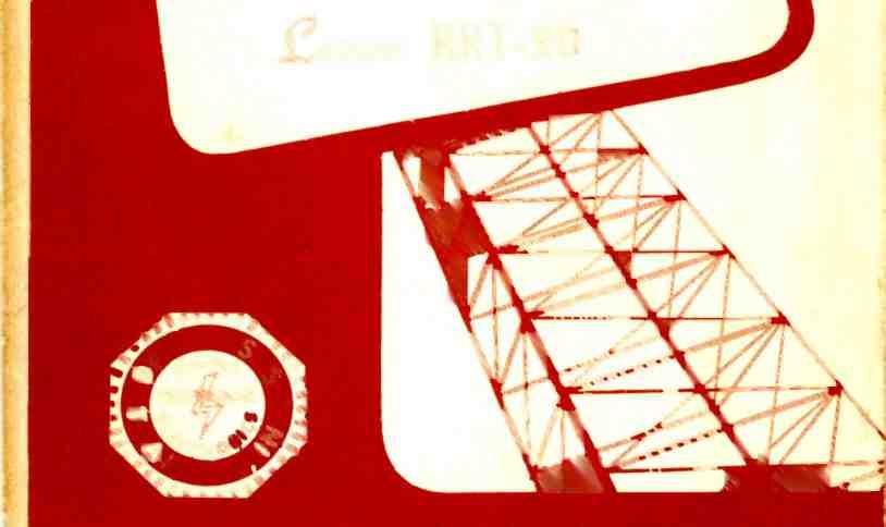
3 Radio Reception and Transmission LESSON RRT -20 THE CATHODE -RAY OSCILLOSCOPE CHRONOLOGICAL HISTORY OF RADIO AND TELEVISION DEVELOPMENTS January 1, Fifty -five television transmitters in operation. and 951,435 television receivers in use. January 11, Coaxial Cable connection established between Eastern TV network and Midwest network..january 20, Presidential inauguration ceremonies televised. It was estimated that 10,000,000 televiewers witnessed the affair. DE FOREST'S TRAINING, INC N. ASHLAND AVE., CHICAGO 14, ILLINOIS
4 RADIO RECEPTION AND TRANSMISSION LESSON RRT -20 THE CATHODE -RAY OSCILLOSCOPE INDEX The Cathode -Ray Oscilloscope The Cathode -Ray Tube The Electron Electron Gun Deflection of the Beam Page 3 Page 4 Page 6 Page 7 Page 8 CRO Time Base Circuit Page 12 How the Thyratron Operates Page 14 Block Diagram of a 'Scope Circuit Page 16 How Screen Patterns Are Produced Page 18 Operating Controls On a 'Scope Page 21 Practical Applications of the 'Scope Page 23 Waveform Observation Page 24 Signal Tracing Page 26 Amplifier Gain Measurements Page 26 Amplifier Passband or Frequency Response Page 28 Frequency Determination Page 29 Lissajous Figures Page 29 * * * * * RRT-20 Nothing really is impossible -there are ways that lead to everything, and if we have sufficient will, we will always have sufficient means. It is often merely as an excuse that we say things are impossible. -Selected


5 Lesson RRT -20 Page 3 E THE CATHODE -RAY OSCILLOSCOPE Most of the previous explanations, concerning the electrical actions in radio circuits and testing instruments, involved the generation and measurement of alternating voltages and currents. Also, in most cases, proper operation of the equipment can be determined by checking at certain points in the circuit for the amplitude or frequency of an alternating voltage or current. Cathode -ray oscilloscope with all controls clearly marked for quick and easy adjusting. Courtesy Precision Apparatus Company
6 Page 4 Lesson RRT -20 However, in radio and particularly television, there are circuits in which the a -c waveform is of major importance. Conventional types of meters can measure the average, effective or peak amplitudes of a -c and its frequency can be measured by checking against the output of a calibrated oscillator. For these tests, the waveform is unimportant or assumed to be correct, and although a distorted waveform may affect the reading, the meter can not indicate this condition. For example, when the output of a speaker is distorted, the waveform of its input differs from that of the original signal and the operation is not satisfactory although the input may be of proper amplitude and frequency. Therefore, some type of equipment is needed to indicate the actual waveform of a -c voltages which exist in circuits under test. In many explanations, it is common practice to represent an alternating voltage by means of a picture or graph, which shows the changes of amplitude and polarity during the period of time necessary to complete one or more complete cycles. An amplitude -time graph, of the type illustrated in Figure 1, gives most of the information about a waveform without necessitating any mental calculations to interpret the picture. It is desirable, therefore, that the waveform determining device produce a graph of this kind so that an alternating voltage can be studied thoroughly by an observer and this is accomplished with an instrument known as a "Cathode-Ray Oscilloscope ". The cathode -ray oscilloscope, abbreviated "cro" and sometimes called an "Oscillograph", has been described as a vtvm which, as an indicating device, employs a luminous pattern on a screen in place of a pointer that moves across a calibrated scale. Although this instrument can be employed for voltage amplitude measurements as well äs many other indications, its primary purpose is to permit the observation of voltage waveforms. The most important component in the cro, and that which makes the visual observation of the waveforms possible, is an evacuated electron tube, called a "Cathode -Ray Tube ", larger in size than an ordinary receiving tube. Because of its somewhat complex construction, and the fact that its mode of operation is different from that of the tube types described so far, a brief explanation of the cathode -ray tube will be given first. THE CATHODE -RAY TUBE Many types of cathode -ray tubes have been developed and as uses for these tubes increased, it


7 Lesson RRT -20 Page 5 became necessary to design them with characteristics to satisfy the new requirements. Cathode -Ray tubes are employed in television cameras and receiving equipment, radar, laboratory apparatus, etc., but in this lesson, only the type used in the cro will be described. As illustrated in the drawing in Figure 2, the general con- several anodes and deflection plates; while the inner surface of the large end of the glass envelope is coated with a fluorescent material called the screen. As in ordinary radio tubes, the cathode is the source of electrons, but in the crt, they are attracted toward the screen by the anodes that operate at high positive po- Experimental set -up showing how cathode -ray oscilloscope is used to check the frequency characteristics of chime tubes. Courtesy Revere Copper and Brass Incorporated struction of this type of cathode- tentials. The intensity of the ray tube, abbreviated "crt", in- electron stream is determined eludes a heater, a cathode, a grid, by the bias voltage applied to the


8 Page 6 Lesson RRT -20 control grid, while its lateral movements are determined by the voltages applied to the vertical and horizontal deflection plates. Thus, the entire action of the cathode -ray tube depends upon the proper control of the elec- THE ELECTRON All matter is made up of at least 92 fundamental constituents commonly called elements. These elements can exist, either in the free state such as iron, oxygen, All- purpose 5 -inch oscilloscope suitable for the development laboratory and service shop. Courtesy Hickok Electrical Instrument Company trons, and before taking up the details of these controls, it will be well to review a few facts concerning the electron itself. carbon, copper, aluminum, sulphur, lead and mercury, or in chemical combination with other elements as they are found in
9 Lesson RRT -20 Page 7 compounds. The smallest unit into which an element can be divided and still retain all of its original characteristics is the atom. Combinations of atoms, or subdivisions of compounds, result in another fundamental unit, the molecule, which is the smallest unit of any compound. Theoretically, the atom has been subdivided further into a positively charged center region or "nucleus ", and a surrounding cloud of negatively charged particles called electrons. In the atoms of metallic elements, some of the electrons are held loosely and hence move about, even shifting from one atom to another. Whenever conditions are such that a large number of the free electrons move in the same direction at one time, a "flow" of electricity is said to be taking place. Within the metal atoms, the electrons revolve around the central nucleus at extremely high speeds, and if heat is applied, their velocities are increased. When the metal becomes hot enough to glow, some electrons acquire sufficient speed to break away from its surface. This action, which is most prominent when the metal is heated in a vacuum, is utilized in most electron tubes to produce the needed supply of electrons ; the metal in this case being called the cathode. The mass of an electron has been estimated by scientists to be approximately 9 X 10⁻²'. gram. It would require 346 billion, billion, billion such minute particles to weigh one ounce. In a crt employing an accelerating potential of 2000 volts, the speed of the electrons is approximately 2.67 X 10" centimeters per second. This is equivalent to 59,700,000 miles per hour and at this speed, they would travel a distance equal to the circumference of the earth at the equator in 11/ seconds. The speed will vary with the square root of the accelerating potential. Therefore, in the above example, it would be necessary to raise the accelerating potential to 8000 volts in order to double the velocity. ELECTRON GUN As shown in the cross section view of Figure 2, the cathode -ray tube can be divided into three main sections. 1: The electron gun which contains the various electrodes that produce the cathode ray, 2: The deflection system which, in this case, consists of two pairs of plates and 3: The screen which consists of a coating on the inside of the large end of the glass envelope. Starting at the left of Figure 2, the cathode is in the form of a cylindrical nickel sleeve, inside of which is the heater that has a coating of insulating material (aluminum oxide) to prevent
10 4 Page 8 Lesson RRT -20 its shorting to the cathode. The control grid, also in the form of a cylindrical sleeve, contains a disk near its forward end and is mounted so as to surround the cathode. The first anode is a somewhat longer cylindrical sleeve, and contains two or more disks with openings in the center, like that of the control grid. Finally, also in the form of a sleeve, is the second anode, which is somewhat larger in diameter, and usually contains no disks. As in ordinary amplifier tubes, the control grid operates at a negative potential with respect to the cathode, but here the first anode operates at a few hundred volts positive, and the second anode at from 1000 to several thousand volts positive. Being attracted by the positive first anode, the electrons are drawn away from the cathode and through the opening in the disk of the grid. Many electrons are collected or stopped by the various disks, and only those which are traveling along the center axis of the tube are able to pass through all the openings and continue in the direction of the screen. The highly positive potential on the second anode accelerates the remaining fine stream of electrons to a high velocity so that they continue through the tube and strike the screen. This electron stream, or cathode ray, is very small in diameter, due to the small openings in the disks of the grid and first anode. Thus, the electron beam which strikes the screen is on the order of only two or three hundredths of an inch in diameter. The fluorescent material, of which the screen is composed, glows under the electron bombardment, and thus a small round dot of light appears on the face of the tube. A second factor which determines the diameter of the electron beam, or dot of light on the screen, is the difference in potential between the first and second anodes. Because of this difference, an electrostatic field of force exists between these anodes, and this field has the effect of confining the electron beam to a small cross -sectional area. Thus, it is possible to adjust or "focus" the spot on the screen by changing the difference of potential between the two anodes. In practical crt circuits, this focusing of the spot is accomplished by means of a potentiometer which permits changing the potential of the first anode, while that of the second anode is kept constant. DEFLECTION OF THE BEAM Up to this point of the explanation, the spot of light would remain stationary at about the center of the screen and in order lti


11 Lesson RRT -20 Page 9 that the tube can be of practical use, it is necessary to move the spot so that the desired pattern or waveform can be traced. This is the function of the deflection electrodes, labeled vertical which they deflect the electron stream, not according to their physical positions in the tube. This method of electron stream deflection, known as the "electrostatic" system, operates on the Checking the circuit operation in an oscilloscope with the aid of a high - impedance vacuum -tube voltmeter. Courtesy Heath Company and horizontal plates in Figure 2. These consist of me al sheets, having the general shape and location shown, which are named "vertical" or "horizontal" in accordance with the direction in principle that like electrical charges repel and and unlike charges attract. For example, consider an end view of the four deflection plates, shown in Figure 3, with the electron stream
12 Page 10 Lesson RRT -20 traveling from the cathode of the electron gun out of the page toward you. If a d -c voltage, EH, is applied to the horizontal plates D1 and Do, so that D2 is positive and D1 negative, the negative electrons of the cathode ray will be attracted by D2 and repelled by D1, so that the stream, and consequently the luminous spot on the screen, will be deflected to the right as indicated by the small arrows. If the polarity of the applied voltage EH is reversed, so that deflection plate D1 becomes positive and D2 negative, the electron stream will be deflected to the left in the figure. The amount of deflection (distance the spot moves from the center of the screen) is determined by the magnitude of the applied voltage. If instead of d -c, the voltage EH is a -c, the spot on the screen will be moved continually from side to side in accordance with the variations of the applied voltage. In the same manner, a voltage Ev applied to the vertical deflection plates, D3 and D4, will cause the stream to be deflected upward when D3 is positive and D4 negative, and downward when D4 is positive and D3 negative. Likewise, if E, is alternating, the spot will move up and down on the screen in accordance with the variations of the applied voltage. When both a -c voltages, E, and EH, are applied at the same time, the path of the spot on the screen will form a more or less complex pattern, as it will then be controlled by the instantaneous values of the various attracting or repelling potentials of all four deflecting plates. If the screen material were such that, at any instant, it would glow only at the point at which the cathode -ray electrons are impinging, it would be difficult for the human eye to obtain a satisfactory picture of the path of the spot. The human eye retains an image for a short period of time and this ability can be detected by watching a bright spot on a spinning wheel. After a certain speed of rotation is attained, the bright spot may appear as a complete circle. To aid the eye in seeing the path traversed by the spot, the crt screen is coated with a material which glows for a short time after the electron stream has moved to another position. Thus the path of the rapidly moving spot is made to appear as a distinct and stationary line. Different uses demand various degrees of persistence or duration of this after -glow and the screen of the tube may be referred to as having a short, medium, or long persistence. By employing different kinds of material for the screen, the trace may be made to appear green, yellow, blue or white. For some


13 Lesson RRT -20 Page 11 applications one color may be preferred to all others. Information on the crt may be obtained from the tube designation and although the nomenclature is not completely standardized, certain methods of convey- ing information on tubes are followed by many manufacturers. In this system, the first number denotes the maximum diameter of the envelope in inches. The letter P with a number following it, indicates the type of fluorescent screen. All other letters between r $1 a ALLEN.O MONT LRNORITGRICN,vNC. sraw, V- POSIÜION UP, 'DOWN N;PNSITIGN LEV NINGNT SWEEP RANGE N01. Cathode -ray oscillograph designed for general developmental and research laboratory work. Courtesy Allen B. DuMont Laboratories, Inc.
14 Page 12 Lesson RRT -20 the first number and the letter P denote differences in gun construction, etc., between tubes of the same size and screen material. P1 and P2 indicate green screens; P4 white, and P5 light blue. A tube designated as 9AP4 has a diameter of 9 ", an accelerating or screen grid, and a white screen. Additional information may be found in tube manuals and catalogs. As most graphs show amplitude in a vertical direction, the voltage to be observed is usually applied to the vertical deflection plates of the crt. However, if this is the only deflection voltage applied, a vertical line or trace will be produced on the screen, as explained for Figure 3. The length of this line will be indicative of the peak amplitude of the applied voltage, Ev, but no information will be obtained concerning its waveform. In order to "spread" the trace in a horizontal direction, and thus produce a pattern having the shape of a desired amplitude -vstime graph like Figure 1, a second deflection voltage E,a must be applied to the horizontal plates. In oscilloscope work, this horizontal deflection voltage is called the "time base" or "sweep." The waveform of the time base voltage depends upon the application of the crt. In most oscilloscope work, the sweep voltage requires a waveform that moves the spot at a steady speed from left to right across the screen, immediately snaps it back to the left side, and then starts another steady left -to-right sweep. The left -to-right movement must be at uniform speed in order that equal distances on the horizontal axis of the pattern will represent equal units of time. If a true picture of the wave shape is desired, the common sine wave voltage cannot be used as a sweep because it would cause the horizontal speed of the spot on the screen to vary continuously. To deflect the cathode -ray beam so that the spot sweeps across the screen at a linear or constant speed, it is necessary to apply a deflection voltage which changes uniformly from zero to maximum, and then almost instantly jumps back to zero. A change of this type is called a "sawtooth voltage" or "linear time base ", and has a waveform similar to that shown in Figure 4 -A. CRO TIME BASE CIRCUIT The portion of the oscilloscope circuit which produces the needed sawtooth horizontal deflection voltage, often termed "sweep voltage ", is shown in Figure 4 -B. The tube V is a gas -filled triode, called a thyratron, across which any one of a group of four condensers can be connected by means of switch S. Resistors R2


15 Lesson RRT -20 Page 13 and R :t form a voltage divider across the B supply, with the voltage drop across R3 employed as a bias for the grid -cathode circuit. However, the condenser will charge through resistor R1 and the voltage across it and the tube will increase at a steady rate Internal gun arrangement for a two -gun cathode -ray tube. Courtesy Electronic Tube Corporation With the tube in operating condition and switch S in the position shown, when the B supply circuit is closed there will be current in the voltage divider and the resulting drop across R3 will impress a negative voltage on the grid. Condenser C1 is connected directly across the tube from plate to cathode therefore the plate voltage will always be equal to its charge. With the condenser discharged there will be no voltage across it and, when the B supply circuit is first closed, there will be zero plate voltage across the tube. as shown between points 1 and 2 of the curve in Figure 4 -A. Due to the drop across R3, the tube is biased to plate current cutoff at the reduced values of plate voltage and therefore is non- conductive. As the voltage across the condenser rises to some predetermined value, the plate circuit of the tube becomes conductive and the condenser discharges through it. Due to actions that will be explained in following paragraphs, the condenser discharge is extremely rapid and the voltage across it reduces as indicated be-
16 Page 14 Lesson RRT -20 tween points 2 and 3 on the curve of Figure 4 -A. With the condenser and plate voltage reduced to zero, the plate circuit of the tube becomes non -conductive and the action repeats as indicated through points This "saw- tooth shaped" voltage across C1 is coupled through Ce and appears as the output voltage E0 of the circuit. HOW THE THYRATRON OPERATES The ability of the thyratron tube to function in the manner explained above is due to the fact that the gas with which it is filled will "ionize" when a high enough difference of potential exists between the cathode and plate. In the earlier explanations of gaseous rectifier tubes, ionization was mentioned, but to clarify the operation of thyratron tubes, the following details will be of benefit. Every gas, solid, or liquid is made up of extremely small particles, called molecules, which are composed of smaller parts called atoms that, in turn consist of a positively charged central nucleus and a number of negatively charged electrons. While the electrons are often thought of as being merely negative charges of electricity, it will simplify this explanation to think of them as extremely small particles of matter, each carrying a negative charge. Because unlike electrical charges attract each other, the positive nucleus of the atom attracts the negative electrons which rotate around it, much as the earth travels in its orbit around the sun. When there are enough electrons to balance the positive charge of the nucleus, the atom is electrically neutral or normal. In the gas -filled thyratron tube, there are always a few free electrons moving about at random, the neutral atoms having no attraction for them. However, when an external voltage is impressed across the plate and cathode, with the plate positive, these free electrons are attracted by and immediately move toward the positive plate at a rapidly increasing speed. But, traveling through a space which contains the neutral gas atoms, they collide with some of them, dislodge an electron or two from each, and then continue on toward the positive plate. The electrons knocked out of the atoms are also attracted toward the plate, and on their way collide with other gas atoms and free more electrons. Although there were but a few free electrons to begin with, in a very short time a large number are moving toward the plate of the tube. When an electron is knocked off, an atom is no longer neutral


17 Lesson RRT -20 Page 15 but has a positive charge, and is called an "ion ". With a positive charge, the ion is attracted toward the cathode and tends to move in a direction opposite to that of the electrons. Thus there will be a stream of electrons moving toward the plate and a stream of ions moving toward the cathode. trons from cathode to plate. This stream of electrons is an electric current and thus the gas, which is normally an electrical insulator, becomes an electrical conductor when ionized. The external voltage necessary to ionize the gas and "fire" the tube depends upon the type and The Philco junior 'scope, model 7019, shown here top center, is a compact portable low -cost oscilloscope. Courtesy Philco Corporation Electrons which reach the plate are drawn through the external voltage supply and returned to the cathode thus, within the tube, there is a constant stream of elec- pressure of the gas, the shape and spacing of the electrodes and the bias voltage on the grid. Unlike the high vacuum type of electron tube, in which the grid voltage
18 Page 16 Lesson RRT -20 controls the plate current at all times, in the thyratron the grid voltage controls only the value of plate voltage at which the tube fires. Once the gas is ionized and plate current is established, the grid loses all control and the current continues until the plate voltage is reduced to a relatively low value. The value of the "firing" or igniting plate potential can be varied by adjusting the grid bias but, when fired, the tube remains conductive until the plate potential is reduced to the extinguishing or "drop out" value. Going back to the curve of Figure 4 -A, points 2 and 4 represent the instants at which the voltage across condenser C1 and the plate circuit of tube V, Figure 4 -B, rises to the igniting value. Acting as an electrical conductor, the ionized gas permits the condenser to discharge almost instantly and the plate voltage reduces to the drop out value indicated by points 1, 3 and 5 on the curve of Figure 4 -A. The frequency of the sawtooth voltage produced by the oscillator or generator of Figure 4 -B is determined by the CR time constant of the condenser charging circuit which includes variable resistor R1. Different frequency ranges are provided by switch S which connects condensers of different capacitance across the plate cir- cuit of the tube. Variation of frequency, over any range, is obtained by adjusting the movable contact of R1. Usually, the condenser values are such that the frequency ranges overlap slightly and the adjustment of R1 over each range provides a continuous change of output frequency over all ranges. An external supply of a definite frequency can be connected across the "SYNC INPUT" terminal and ground. Connected in the grid circuit of tube V, proper adjustment of variable resistor Rs causes the discharge tube to fire exactly in synchronism with the frequency of the external voltage. The drop across the desired portion of Rs is in series with the drop across R3 in the grid circuit and affects the grid bias. Switch S, and variable resistor R1 are set to provide a frequency approximately equal to that of the external voltage across Rs, then the sliding contact of Rs is adjusted so that the peaks of external voltage will reduce the grid bias sufficiently to fire the tube. BLOCK DIAGRAM OF A 'SCOPE CIRCUIT The arrangement of the various component circuits of a cathode - ray oscilloscope is shown by the block diagram in Figure 5. The crt is drawn in semi -schematic form, while the other units in-
19 Lesson RRT -20 Page 17 elude a vertical amplifier, a time base generator, horizontal amplifier, with low and high -voltage power supplies. The amplifiers are of the resistance -coupled type while the time base generator is similar to that cf Figure 4-13 and all are operated by the low voltage power supply which is like that of the ordinary a -c type of radio receiver. The high voltage supply develops an output that, in different models, may vary from a few hundred to several thousand volts, and connects only to the electron gun of the crt. It is needed to provide the electrons of the cathode ray with sufficient velocity to produce a bright spot on the screen. Normally, the voltage to be checked is applied to the binding post VA, which is connected to the input of the vertical amplifier and after amplification, is applied to the vertical deflection plates of the crt. The sawtooth time base generator, adjusted to the desired frequency, is connected through switch S2 to the input of the horizontal amplifier, the output of which is applied to the horizontal deflection plates. In order to maintain a stationary pattern on the screen, it is necessary that the sweep voltage frequency have some definite whole- number relationship with the frequency of the voltage under study. This is accomplished first, by adjusting the frequency of the sweep generator, and second, by applying a portion of the input voltage to the control grid of the sweep oscillator through switch S,. If the voltage under study is undesirable for use in synchronizing the sweep oscillator, as in the case of checking certain phase relationships, external synchronization can be obtained from an external voltage by throwing switch S1 to the lower position, which connects the "EXT. SYNC" binding post to the grid circuit of the sweep generator. If it is desirable to use an external sweep voltage of a particular type, or if the frequency of an unknown voltage is to be checked, switch S2 can be set to the lower position. This disconnects the sawtooth input and connects the HA binding post to the input of the horizontal amplifier. This change in connections allows an external voltage to be amplified and then applied to the horizontal deflection plates. In addition to terminals for the input of the horizontal and vertical amplifiers, most 'scopes have binding posts which permit the application of external voltages directly to the crt deflecting plates. These are indicated by the posts marked VP and HP in the drawing.


20 Page 18 Lesson RRT -20 HOW SCREEN PATTERNS ARE PRODUCED Earlier in this lesson it was stated that if a sawtooth sweep voltage is applied to the horizontal plates of the crt, the pattern circular area "S" represents the screen when looking at the face of the crt. In this particular case, Ev and E. are of the same frequency, and therefore, will have the same time Deluxe five -inch oscilloscope adapted for a -m, f -m, and video servicing. Courtesy Supreme Instruments Corporation produced on the screen will be a true amplitude -vs -time graph of the voltage applied to the vertical plates. To follow the action in detail, in Figure 6, curve Ev represents a sine wave voltage to be observed. Curve EH represents the sawtooth sweep voltage and the scale. Voltage Ev is applied to the vertical deflection plates so that it causes the electron beam to be pulled upward during the positive alternation of the wave, and downward during the negative alternation, while EH causes the beam to move from side to
21 Lesson RRT -20 Page 19 side as explained for Figure 3. The phase of EH with respect to Ev is such that EH is at its maximum negative point at the instant that Ev is passing through zero value and going from its negative to its positive alternation. This condition is indicated as time -instant 0, and the information is projected onto the screen area S by means of dotted lines. One line, projected vertically upward from time point 0 on curve EH and another line, projected horizontally to the right from time point 0 on curve Ev, intersect at point 0 on the screen S. This intersection indicates the point at which the spot of light will appear at this instant. Following the same plan, lines projected from points 1 on the EH and Ev curves intersect at point 1 on the screen. Thus, during the interval between time points 0 and 1, voltage Ev has increased in value while voltage EH has decreased. Therefore the spot on the screen has moved from point 0 to point 1. In the same manner, by projecting from the time points of both curves in n'- mbered sequence, the intersection points on the screen trace a path almost exactly like curve Ev. However, shortly before curve EH reaches time point 8, it reverses polarity thereby causing the spot on the screen to move almost in- stantly from right to left and back to point 8 which corresponds to point 0 as the start of a cycle. This rapid movement is indicated by the broken line which, on the screen, slopes upward slightly from the right end of the solid curve to point 8. Although it is extremely short, a definite amount of time is required for this right -to -left or "return" sweep of the beam. This is known as the "flyback" time, and during this period, the movement is so rapid that the spot is almost invisible. The brightness or intensity of the spot on the screen is determined by the value of the bias on the control grid of the crt electron gun, and in some commercial oscilloscopes, means are provided whereby a high negative voltage pulse is applied to the grid during this flyback time. This cuts off the electron beam during this period to prevent the return trace from appearing on the screen. Assuming voltages Ev and EH have a common frequency of 400 cycles, the complete sine curve will be traced on the screen of Figure 6 in 1/400 of a second, and if the action is allowed to continue, the spot will complete 400 traces each second. This speed is possible because of the extremely small mass or weight of the electrons making up the cathode -ray. Due to the fluorescent qualities


22 Page 20 Lesson RRT -20 of the screen, and the persistence of vision of the human eye, this rapid movement makes the spot appear as an illuminated line or With E, and EH of equal frequency, one complete cycle appears on the screen, but if the frequency of E, is twice that of Checking the performance of a Heath 'scope with a Hewlett- Packard signal generator and harmonic analyzer. Courtesy Heath Company trace, and thus the sine curve will appear as a uniformly illuminated and stationary pattern on the screen. E,,, two complete cycles will appear, and similarly for other ratios. However, to maintain a steady pattern on the screen,
23 Lesson RRT -20 Page 21 there must be a fixed and con- 1. stant whole -number ratio between the frequencies of Ev and EH. If such an integral frequency relationship does not exist, the pattern will move constantly and change in appearance. Different phase relationships or amplitude ratios, between two applied deflection voltages of a given frequency ratio, will produce stationary patterns of different shapes. To sum up, the shape of the pattern produced by the movement of the spot on the crt screen depends upon 1: The frequency relationship, 2. The phase relationship, and 3. The amplitude relationship of the respective deflection voltages. Whether or not the pattern is stationary depends only upon the frequency relationship of the voltages. OPERATING CONTROLS ON A 'SCOPE 3. The front panel of the average commercial oscilloscope, as illustrated in Figure 7, contains the crt screen S, the various operating control knobs, and the input terminal binding posts. The actual locations of the various controls will vary with different 4. makes and models but those shown and listed below will be found on most commercial oscilloscopes. According to the numbers shown in Figure 7, the names and purposes are as follows : 2. INTENSITY -Regulates the intensity or brightness of the pattern on the screen by adjusting the crt control grid bias. It should never be turned up higher than is necessary to produce a readable image. Generally this control incorporates the "ON-OFF" power switch for the entire instrument. When neither a vertical nor a horizontal deflection voltage is being applied to the crt, the intensity control should be turned down until the spot is. not visible because a bright stationary spot may burn a hole in the fluorescent screen. FOCUS -This control adjust the positive potential on the first anode, and by controlling the diameter of the cathode ray, determines the clearness and sharpness of the pattern. VERTICAL POSITIONING -Regulates the value and polarity of a d -c bias voltage applied to the vertical deflection plates, thus permitting the pattern to be shifted up or down on the screen when necessary. HORIZONTAL POSITION- ING - Permits shifting of the pattern in the horizontal direction on the screen by the same means explained above for the vertical positioning control.
24 Page 22 Lesson RRT VERTICAL GAIN - Determines the vertical height of the pattern by regulating the gain of the vertical amplifier. 6. HORIZONTAL GAIN - Determines the horizontal size or width of the pattern by regulating the gain of the horizontal amplifier. Both of these gain controls correspond to the volume control in an audio amplifier. 7. SWEEP FREQUENCY RANGE SELECTOR -A rotary switch for selecting one of several time base frequency ranges. This control is often labeled "Coarse Frequency," and corresponds to switch S of Figure 4 -B. 8. FREQUENCY VERNIER - A continuously variable control, R1 in Figure 4 -B, for adjusting the time base frequency over any one range. This is sometimes labeled "Fine Frequency ". 9. SYNCHRONIZING ADJUST -Cohtrols the magnitude of the synchronizing voltage applied to the grid of the time base generator to cause the pattern to remain stationary on the screen. Corresponding to RS in Figure 4 -B, this control is labeled : "Sync," "Sync Amp ", "Locking", etc. 10. INT -EXT SYNC -A double - throw switch, Si in Figure 5, 11. for selecting as the synchronizing voltage either a part of the signal voltage impressed on the vertical deflecting plates, or an external voltage supplied through the "Ext- Sync" binding post (Figures 5 and 7). INT -EXT SWEEP -A double -throw switch, S2 in Figure 5, for connecting either the sawtooth voltage output of the internal time base generator, or an external voltage supplied through the HA binding post, to the grid of the horizontal amplifier (Figures 5 and 7). The "VP" and "HP" binding posts in Figure 5 are not included in the panel of Figure 7 as they may be located on the side or at the rear of the oscilloscope cabinet. Other binding posts are sometimes provided for special purposes, such as applying a signal to the control grid of the crt and thus permitting the spot to be modulated in intensity as the pattern is traced. An arrangement of this kind is known as the "Z" axis. Another terminal often included, is connected internally to a filament winding of the cro power supply, thus making available a 60 -cycle alternating voltage for test purposes.


25 Lesson RRT -20 Page 23 PRACTICAL APPLICATIONS OF THE 'SCOPE A large number of uses have been developed for this extremely versatile instrument, both within and outside of the field of Radio and Electronics. In the field of Radio Servicing alone, the cathode -ray oscilloscope probably has, or can easily be adapted to have, Checking an electronic power tube with on industrial type oscilloscope and tube checker. Courtesy General Electric Company
26 Page 24 Lesson RRT -20 more applications than any other single piece of test equipment. Although its most important function is the reproduction of a -c waveforms, it can be used also for signal tracing, amplifier gain measurements, as well as frequency bandwidth, phase shift, and distortion tests. It can be employed in receiver alignment, detection of amplifier oscillation and hum voltage, and for frequency determinations. When properly calibrated, the cro can be used as a vtvm to measure current and power in a circuit. The circuit connections and typical waveforms obtained for some of the above mentioned tests and measurements are described in the following paragraphs. WAVEFORM OBSERVATION As most radio or amplifier circuit defects result in some distortion of the signal waveform, a study of the output waveform to determine the type of distortion produced, usually provides a convenient method of locating the particular circuit defect. For example, the a -f output circuit of Figure 8 includes a number of points, A, B, C, etc., to which the oscilloscope test prod, TP, can be connected. This test lead is connected to the cro vertical input terminal, while the 'scope ground terminal is connected to a ground point in the circuit being tested. An undistorted dine wave audio voltage is applied to the grid of tube V1, and with prod TP connected to this point, the cro sweep circuit controls are adjusted until the pattern on the screen consists of one, or two stationary sine wave cycles, as shown in Figure 9 -A. With the waveform of Figure 9 -A obtained when the test prod is touched to the grid of V,, a similar pattern, but inverted due to the phase- reversing action of V1, should be obtained when the prod is placed at point A in Figure 8. Likewise, the original pattern should be seen with the cro test prod at point B, the plate terminal of V2. The fourth point at which this normal sine wave voltage should be found is with the test prod TP at point C. For this test, the cro ground lead should be placed at point D, as indicated by the dashed line. A similar waveform may be obtained with no a -f input applied to the circuit in which case the 60 cps power line voltage may be coupled to the input circuit in some way. In this case, the 'scope sweep circuit must be operating at, or at a submultiple of, 60 cps. If, with prod TP at point A, B, or C, the trace on the screen has the wavy appearance of that of Figure 9 -B, improper filtering of the power supply d -c output is indicated, and may be due to an
27 Lesson RRT -20 Page 25 open filter condenser or shorted filter choke. Should the coupling condenser C, be leaky, then the waveform obtained with prod TP at point A will be as shown in Figure 9 -C. This same condition will cause the signal voltage at points B and CD to have the waveform shown in Figure 9 -D. With one peak "clipped", this waveform is due to either the above mentioned defect or to any other effect that may cause an improper value of grid bias on tube V2. In the case of insufficient bias, the negative peak of the plate voltage, point B, will be flattened or clipped, and if the bias is too high, the positive plate voltage peak will be clipped. One of these conditions will produce the pattern of Figure 9 -D, the other will give this pattern inverted ; the particular pattern resulting in a given case depending upon the number of vertical amplifier stages employed in the oscilloscope, the connections to crt vertical plates, etc. As these design details vary in different makes and models of oscilloscopes, no general rule can be given concerning the polarity of the waveforms produced on the screens. With prod TP at point A. B, or C, the pattern of Figure 9 -D (or this pattern inverted) will be obtained in the event that improper tube operating conditions exist due to a too high or too low B voltage, or to a screen -grid circuit component, R3 or C3, with the wrong value. The voltage waveform at point B will appear as Figure 9 -E if the signal input to the grid of tube Vo is too great in amplitude, that is, if the stage is "overloaded". Note that severe clipping of both peaks is obtained, and the pattern begins to approach a square wave shape. If for some reason there should be no voltage at the screen grid of V., the waveform at the plate, point B, will resemble that shown in Figure 9 -F. In order to reproduce this waveform, a very strong signal input is necessary. An open loudspeaker voice coil is one possible cause for the plate circuit of the output tube V. being too lightly loaded, in which case the waveform at point B will be similar to that shown in Fig- ure 9 -G. On the other hand, if Vo is loaded too heavily, a condition that could be caused by a shorted voice coil, the wave will take on the form shown in Figure 9 -H. If the cathode bypass condenser Co is open, the wave of Figure 9 -A, very low in amplitude, will be found to exist at the cathode of V. at point E. If this condenser is shorted, the tube bias will be affected, and at
28 Page 26 Lesson RRT -20 point B, produce the waveform of Figure 9 -D as explained above. The amplifier in Figure 8 may operate as an oscillator and produce a relatively high- frequency voltage if the placement of its components or the wiring happens to be such that sufficient feedback from plate to grid circuit is obtained. With the 'scope test prod placed at point B, this oscillation may cause the cro screen pattern to have the appearance of that shown in Figure 9 -I. SIGNAL TRACING In the previous lesson on test equipment, the instrument called a Signal Tracer was said to consist of three major parts, namely, a detector, an amplifier, and an indicating device. As the cathode -ray oscilloscope includes an amplifier, and the crt as an indicator, all that is needed to make a complete signal tracer is the addition of some type of detector. This detector may be contained within the 'scope cabinet, in a separate cabinet, or be mounted inside the test probe as in the case of the vtvm and signal tracer described previously. However, to permit checking in the receiver input circuits, usually it is necessary that an additional stage of amplification be employed at the cro input. With an oscilloscope so equipped, a radio receiver can be "signal traced" in the normal manner, by using either a radio station carrier or a modulated r -f generator as the signal source. As shown on the block arrangement in Figure 10, the cro probe detector is not needed at any points in the circuit following the receiver 2nd detector, as here the required demodulation has al- ready been accomplished. Some commercial type oscilloscopes include a phone jack on their front panel so that a headset can be plugged in, and the voltage at the crt vertical plates can be heard as well as seen when the instrument is being used as a signal tracer. AMPLIFIER GAIN MEASUREMENTS The oscilloscope can be employed to obtain a practical approximation of the voltage gain provided by a given amplifier circuit. For this measurement, it is necessary to employ a graphic scale which consists of a transparent material, such as celluloid, that is ruled with vertical and horizontal lines spaced usually one -tenth of an inch apart, and which is shaped to fit over the crt screen. This graphic scale permits direct comparison of the relative amplitudes of the patterns or traces produced on the screen.


29 Lesson RRT -20 Page 27 To measure stage gain, the test circuit is set up as shown in Figure 11. A signal voltage of proper amplitude is applied to stage, point A, is applied to the cro vertical input. For this test, the horizontal sweep circuit is turned off, so that the only deflec- Philco precision visual alignment generator is shown here as it is used for adjusting the performance of an f -m receiver. Courtesy Philco Corporation the input of the amplifier tube the gain of which is to be measured, and the voltage existing at the grid of the following tion will be that due to the voltage under test and as it is applied to the oscilloscope vertical input, the trace will have the form of
30 Page 28 Lesson RRT -20 a vertical line. Then the cro test prod is placed at the grid of tube VI, point B, and the ratio of the lengths of the traces produced with the test prod at points A and B is numerically equal to the voltage gain of the V1 stage. As an example, suppose that when the oscilloscope test prod is at point A in Figure 11, the vertical line covers exactly 8 divisions on the graph scale, as shown at A in Figure 12. When the prod is moved to point B in Figure 11, the vertical trace has a total length of only two - fifths of a division, as at B in Figure 12. Then the voltage gain G is given by : Output Voltage G = Input Voltage Length of Line A Length of Line B 8 40 = - - -= 20_ 2/5 2 By calibrating the oscilloscope in terms of volts -per -graphic scale division, it is possible to use the instrument directly as a vtvm. However, the accuracy is not high, due to the necessity of estimating the length of the trace and when a high degree of accuracy is required, a vtvm should be used. AMPLIFIER PASSBAND OR FREQUENCY RESPONSE The amplitude- frequency response of an amplifier circuit can be checked by using the oscilloscope as an output indicator with the circuit arrangement of Figure 11. Again the graphic scale is used with the vertical deflection divisions being recorded on a sheet of graph paper as the signal generator is adjusted to various frequency values in the band over which the tested circuit operates. In this test, the 'scope prod remains at point A; however, it is very important that the input to the. circuit under test be maintained at a uniform amplitude as the frequency is changed. A vtvm can be connected permanently to point B in Figure 11, to provide a constant check on this input voltage. To obtain an accurate test of this type, the vertical amplifier of the oscilloscope must have a uniform or flat frequency response. Although it may be quite linear over the frequency range for which it was designed, distortion will occur if the frequency is made too high. Data on the frequency limits of various makes of oscilloscopes may be obtained from the manufacturer's specifications and the test should not exceed these limits. However, if the output of the amplifier under test has sufficient amplitude, it may be applied directly to the plates of the cro thereby eliminating possible
31 Lesson RRT -20 Page 29 errors due to the non -linear response of the oscilloscope amplifier. FREQUENCY DETERMINATION The frequency of an unknown alternating voltage can be determined with an oscilloscope by comparing the pattern produced by this voltage with that produced by a voltage of known frequency, or by determining the frequency ratio from the pattern produced when the unknown frequency is applied to one pair of deflecting plates and the known frequency to the other pair. The first system is an indirect method in that the cro sweep frequency must be determined, after which the unknown frequency is compared with that of the sweep voltage. The advantage of this method lies in the simplicity of interpretation of the screen patterns used. The voltage Ex, the frequency of which is to be determined, is applied to the cro vertical input and the sweep frequency controls are adjusted until one or more complete cycles appear on the screen. For example, if five sine wave cycles are produced, as shown in Figure 13, it indicates that five cycles of the vertical input voltage occur during the period of time occupied by one cycle of the sweep voltage. There- fore, the frequency ratio is 5:1. Without touching the sweep circuit controls, the unknown frequency is removed from the cro input and replaced by the output voltage of a calibrated signal generator, the frequency of which is varied until but one cycle appears on the cro screen. At this point, the cro sweep frequency is equal to that indicated on the calibrated dial of the signal generator. If the indicated frequency is 400 cps then, with the predetermined ratio of 5:1, the frequency of the tested voltage is 5 X 400 = 2000 cps. LISSAJOUS FIGURES The second method of frequency determination makes use of what are called "Lissajous Figures ", named after the 19th century French Scientist. These figures are defined as the patterns or curves produced on a cathode - ray oscilloscope screen when a sine wave voltage is applied to each set of deflecting plates. The ratio of the frequencies of the two voltages can be determined from the patterns produced, and by knowing this ratio and the frequency of one of the voltages, the frequency of the other can be found. Note, that in this method the cro sweep voltage does not enter the problem ; in fact the sweep circuit is not used at all, the horizontal amplifier being switched to the external
32 Page 30 Lesson RRT -20 horizontal input terminal HA in Figure 5. The Lissajous Figure method of frequency determination employs an equipment set -up as shown in Figure 14 where one source of alternating voltage is connected to the oscilloscope vertical input, the other to the horizontal input. For example, suppose the output of Signal Source No. 1 is of unknown frequency, while Signal Source No. 2 consists of a conventional a -f or r -f signal generator, the calibration of which is known to be correct. As explained for the passband test of an amplifier, if the frequencies to be compared are so high that they exceed the rated band pass limits of the oscilloscope vertical and horizontal amplifiers, the input voltages, if great enough in amplitude, can be applied directly to the crt deflecting plates. Continuing with the example, suppose that the pattern produced on the screen is like that shown in Figure 15. The fre- quency ratio of the two voltages can be found by means of the mutually perpendicular lines MN and XY, which just touch the edges of the loops. These lines can be imaginary, or they can consist of two of the graphic scale lines with the pattern positioned so that it edges fall directly on the lines. The frequency ratio of the vertical to the horizontal voltage is equal to the ratio of the number of points at which the Lissajous pattern intersects line XY to the number of points at which it intersects line MN. In the example of Figure 15, the horizontal to vertical frequency ratio is 3 to 2. Therefore, if the output of the Signal Source No. 2 has a frequency of 600 cps, as read on its dial, then the frequency of the output of Signal Source No. 1 must be 3/2 x 600 = 900 cps. As the frequency ratio increases, it becomes increasingly difficult to interpret the figures and when high ratios are used, accuracy depends somewhat on the skill of the observer.
33 Lesson RRT -20 Page 31 IMPORTANT WORDS USED IN THIS LESSON CATHODE RAY -A stream of fast moving electrons under the influence of an applied voltage. DEFLECTION PLATES -Two sets of parallel plates between which the electron stream in a cathode -ray tube must pass. When electrically excited, the plates deflect the stream in either a vertical or horizontal direction. ELECTRON GUN -The electrode assembly mounted in the neck of a cathode -ray tube, and consisting of heater, cathode, control grid, and accelerating anodes. It is here that the electron stream is developed. FLUORESCE -To become luminous or give off light when excited by a stream of fast moving electrons. HORIZONTAL PLATES -The pair of deflection plates in a cathode - ray tube that swing the electron stream from left to right in a horizontal plane. LISSAJOUS FIGURES -The variety of curves obtained on the screen of a cathode -ray tube when sine wave voltages of different frequencies and phase relations are impressed on the vertical and horizontal deflection plates. OSCILLOSCOPE -An instrument for developing on the screen of a cathode -ray tube a visual graphic image of a rapidly varying electrical quantity. SAW- TOOTH -A waveform resembling the teeth of a saw. It rises linearly to a peak value, then drops very rapidly to zero. SCREEN -The deposit of fluorescent salts on the inner surface of the large end of a cathode -ray tube. This salt glows when excited by a stream of electrons. SCREEN BURNING -The formation of discolored spots on the screen of a cathode -ray tube due to the electron stream remaining in a fixed position for too long a time. Such burning impairs the sensitivity of the screen in those areas.
34 Page 32 Lesson RRT -20 SWEEP GENERATOR -An electron oscillator that develops a saw - tooth voltage to deflect the electron stream at a constant rate from left to right across the screen of a cathode -ray tube. SYNCHRONIZING CONTROL -The oscilloscope control which permits a portion of the vertical input voltage to be impressed on the grid of the sweep generator tube to maintain the image in a stationary position on the screen. VERTICAL PLATES -The pair of deflection plates in a cathode - ray tube that deflects the electron stream up and down in a vertical plane.
35 SllOn NI 30111tlWv 30V11On
36 ti
37


38 E FROM OUR Precede" WHY ARE WE ON NOTEBOOK THIS EARTH? To help the rest who are on it, not only,.everything that bath lif help humans, but. friendship to win affection, encourage and show with their loads, to the ire. To make everyone about not the worse for our comfort and iesp make all lour feel our d utmost to To a bit less burdenby us while. directly influenced more worth some, a bit happier and From that, if we have any imagination, we shall widen our activity so as to include those outside our personal range. We shall work for the overthrow everywhere of opprivilege. We shall pression, of unj body. We demand a sg uat'e deal for every. to all wheels that shall put our shoulders f the mud of tradipushed inhumanity on to are being p etence and tional income the high road of progress. And, being thus occupied, we shall cease to whimper about why we are on this earth. We shall know. Yours for success, COPY RIGH TRAINING FORESTS TF INC IN U SA
CHAPTER 4 OSCILLOSCOPES
 CHAPTER 4 OSCILLOSCOPES 4.1 Introduction The cathode ray oscilloscope generally referred to as the oscilloscope, is probably the most versatile electrical measuring instrument available. Some of electrical
The Cathode Ray Tube
 Lesson 2 The Cathode Ray Tube The Cathode Ray Oscilloscope Cathode Ray Oscilloscope Controls Uses of C.R.O. Electric Flux Electric Flux Through a Sphere Gauss s Law The Cathode Ray Tube Example 7 on an
OPERATING INSTRUCTIONS FOR SYLVANIA. Type I08 Cathode-Ray Oscilloscope. Sylvania Electric Products Inc. Industrial Apparatus. Emporium, Pennsylvania
 OPERATING INSTRUCTIONS FOR SYLVANIA Type I08 Cathode-Ray Oscilloscope Sylvania Electric Products Inc. Industrial Apparatus Plant Emporium, Pennsylvania OPERATING INSTRUCTIONS FOR Sylvania Type 08 Cathode-Ray
Electrical and Electronic Laboratory Faculty of Engineering Chulalongkorn University. Cathode-Ray Oscilloscope (CRO)
") 2141274 Electrical and Electronic Laboratory Faculty of Engineering Chulalongkorn University Cathode-Ray Oscilloscope (CRO) Objectives You will be able to use an oscilloscope to measure voltage, frequency
2141274 Electrical and Electronic Laboratory Faculty of Engineering Chulalongkorn University Cathode-Ray Oscilloscope (CRO) Objectives You will be able to use an oscilloscope to measure voltage, frequency
Elements of a Television System
 1 Elements of a Television System 1 Elements of a Television System The fundamental aim of a television system is to extend the sense of sight beyond its natural limits, along with the sound associated
CATHODE RAY OSCILLOSCOPE. Basic block diagrams Principle of operation Measurement of voltage, current and frequency
 CATHODE RAY OSCILLOSCOPE Basic block diagrams Principle of operation Measurement of voltage, current and frequency 103 INTRODUCTION: The cathode-ray oscilloscope (CRO) is a multipurpose display instrument
CATHODE-RAY OSCILLOSCOPE (CRO)
") CATHODE-RAY OSCILLOSCOPE (CRO) I N T R O D U C T I O N : The cathode-ray oscilloscope (CRO) is a multipurpose display instrument used for the observation, measurement, and analysis of waveforms by plotting
CATHODE-RAY OSCILLOSCOPE (CRO) I N T R O D U C T I O N : The cathode-ray oscilloscope (CRO) is a multipurpose display instrument used for the observation, measurement, and analysis of waveforms by plotting
CHAPTER 3 OSCILLOSCOPES AND SIGNAL GENERATOR
 CHAPTER 3 OSCILLOSCOPES AND SIGNAL GENERATOR OSCILLOSCOPE 3.1 Introduction The cathode ray oscilloscope (CRO) provides a visual presentation of any waveform applied to the input terminal. The oscilloscope
OSCILLOSCOPE AND DIGITAL MULTIMETER
 Exp. No #0 OSCILLOSCOPE AND DIGITAL MULTIMETER Date: OBJECTIVE The purpose of the experiment is to understand the operation of cathode ray oscilloscope (CRO) and to become familiar with its usage. Also
CATHODE RAY OSCILLOSCOPE (CRO)
") CATHODE RAY OSCILLOSCOPE (CRO) 4.6 (a) Cathode rays CORE Describe the production and detection of cathode rays Describe their deflection in electric fields State that the particles emitted in thermionic
CATHODE RAY OSCILLOSCOPE (CRO) 4.6 (a) Cathode rays CORE Describe the production and detection of cathode rays Describe their deflection in electric fields State that the particles emitted in thermionic
THE OPERATION OF A CATHODE RAY TUBE
 THE OPERATION OF A CATHODE RAY TUBE OBJECT: To acquaint the student with the operation of a cathode ray tube, and to study the effect of varying potential differences on accelerated electrons. THEORY:
The Knowledge Bank at The Ohio State University. Ohio State Engineer
 The Knowledge Bank at The Ohio State University Ohio State Engineer Title: Creators: Principles of Electron Tubes Lamoreaux, Yvonne Issue Date: 1944-03 Publisher: Ohio State University, College of Engineering
THE OPERATION OF A CATHODE RAY TUBE
 THE OPERATION OF A CATHODE RAY TUBE OBJECT: To acquaint the student with the operation of a cathode ray tube, and to study the effect of varying potential differences on accelerated electrons. THEORY:
? Me ???????? ?????? & > Dec. 14, ??? 2,455,992 ???.. ????? T. T. GOLDSMITH, Jr., ET AL CATHODE-RAY TUBE AMUSEMENT DEVICE. Filed Jan, 25, 1947
 Dec. 14, 1948. Filed Jan, 25, 1947 T. T. GOLDSMITH, Jr., ET AL CATHODE-RAY TUBE AMUSEMENT DEVICE 2,455,992 $?* do??? (TD S Y O s??????????? & > 8+ N zz +aosz No.O2 ---- g s S ÀY vr N???..??????? Me V)??
Using an oscilloscope - The Hameg 203-6
 Using an oscilloscope - The Hameg 203-6 What does an oscilloscope do? Setting up How does an oscilloscope work? Other oscilloscope controls Connecting a function generator Microphones audio signals and
These are used for producing a narrow and sharply focus beam of electrons.
 CATHOD RAY TUBE (CRT) A CRT is an electronic tube designed to display electrical data. The basic CRT consists of four major components. 1. Electron Gun 2. Focussing & Accelerating Anodes 3. Horizontal
Experiment 9A: Magnetism/The Oscilloscope
 Experiment 9A: Magnetism/The Oscilloscope (This lab s "write up" is integrated into the answer sheet. You don't need to attach a separate one.) Part I: Magnetism and Coils A. Obtain a neodymium magnet
The Venerable Triode. The earliest Triode was Lee De Forest's 1906 Audion.
 The Venerable Triode The very first gain device, the vacuum tube Triode, is still made after more than a hundred years, and while it has been largely replaced by other tubes and the many transistor types,
3B SCIENTIFIC PHYSICS
 3B SCIENTIFIC PHYSICS Complete Fine Beam Tube System 1013843 Instruction sheet 10/15 SD/ALF If it is to be expected that safe operation is impossible (e.g., in case of visible damage), the apparatus is
Lecture 17 Microwave Tubes: Part I
 Basic Building Blocks of Microwave Engineering Prof. Amitabha Bhattacharya Department of Electronics and Communication Engineering Indian Institute of Technology, Kharagpur Lecture 17 Microwave Tubes:
4.9 BEAM BLANKING AND PULSING OPTIONS
 4.9 BEAM BLANKING AND PULSING OPTIONS Beam Blanker BNC DESCRIPTION OF BLANKER CONTROLS Beam Blanker assembly Electron Gun Controls Blanker BNC: An input BNC on one of the 1⅓ CF flanges on the Flange Multiplexer
J.J. Thomson, Cathode Rays and the Electron
 Introduction Experimenters had noticed that sparks travel through rarefied (i.e. low pressure) air since the time of Franklin. The basic setup was to have two metal plates inside a glass tube. The air
Tutorial Cathode Rays Year 12 Physics - Module 9.3 Motors and Generators
 Tutorial 9.4.1.2 Cathode Rays Year 12 Physics - Module 9.3 Motors and Generators For use with Lesson 9.4.1 Cathode Rays 1. Identify the properties of cathode rays that indicated that they might be particles.
NAPIER. University School of Engineering. Advanced Communication Systems Module: SE Television Broadcast Signal.
 NAPIER. University School of Engineering Television Broadcast Signal. luminance colour channel channel distance sound signal By Klaus Jørgensen Napier No. 04007824 Teacher Ian Mackenzie Abstract Klaus
3B SCIENTIFIC PHYSICS
 B SCIENTIFIC PHYSICS Triode S 11 Instruction sheet 1/15 ALF 1 5 7 1 Guide pin Connection pins Cathode plate Heater filament 5 Grid Anode 7 -mm plug for connecting anode 1. Safety instructions Hot cathode
Reading 21 ELECTRON TUBES
 Reading 21 Ron Bertrand VK2DQ http://www.radioelectronicschool.com ELECTRON TUBES One of the most significant developments of the early twentieth century was the invention of the electron tube. The British
S op o e p C on o t n rol o s L arni n n i g n g O bj b e j ctiv i e v s
 ET 150 Scope Controls Learning Objectives In this lesson you will: learn the location and function of oscilloscope controls. see block diagrams of analog and digital oscilloscopes. see how different input
Presented by: Amany Mohamed Yara Naguib May Mohamed Sara Mahmoud Maha Ali. Supervised by: Dr.Mohamed Abd El Ghany
 Presented by: Amany Mohamed Yara Naguib May Mohamed Sara Mahmoud Maha Ali Supervised by: Dr.Mohamed Abd El Ghany Analogue Terrestrial TV. No satellite Transmission Digital Satellite TV. Uses satellite
2.2. VIDEO DISPLAY DEVICES
 Introduction to Computer Graphics (CS602) Lecture 02 Graphics Systems 2.1. Introduction of Graphics Systems With the massive development in the field of computer graphics a broad range of graphics hardware
Burlington County College INSTRUCTION GUIDE. for the. Hewlett Packard. FUNCTION GENERATOR Model #33120A. and. Tektronix
 v1.2 Burlington County College INSTRUCTION GUIDE for the Hewlett Packard FUNCTION GENERATOR Model #33120A and Tektronix OSCILLOSCOPE Model #MSO2004B Summer 2014 Pg. 2 Scope-Gen Handout_pgs1-8_v1.2_SU14.doc
University of Utah Electrical & Computer Engineering Department ECE1050/1060 Oscilloscope
 University of Utah Electrical & Computer Engineering Department ECE1050/1060 Oscilloscope Name:, A. Stolp, 2/2/00 rev, 9/15/03 NOTE: This is a fill-in-the-blanks lab. No notebook is required. You are encouraged
RICHLAND COLLEGE School of Engineering Business & Technology Rev. 0 W. Slonecker Rev. 1 (8/26/2012) J. Bradbury
 J. Bradbury") RICHLAND COLLEGE School of Engineering Business & Technology Rev. 0 W. Slonecker Rev. 1 (8/26/2012) J. Bradbury INTC 1307 Instrumentation Test Equipment Teaching Unit 8 Oscilloscopes Unit 8: Oscilloscopes
RICHLAND COLLEGE School of Engineering Business & Technology Rev. 0 W. Slonecker Rev. 1 (8/26/2012) J. Bradbury INTC 1307 Instrumentation Test Equipment Teaching Unit 8 Oscilloscopes Unit 8: Oscilloscopes
PRACTICAL APPLICATIONS OF ELECTRONICS IN ANAESTHESIA. G. A. HAY Department of Medical Physics, University of Leeds
 Brit. J. Anaesth. (1955), 27, 622 PRACTICAL APPLICATIONS OF ELECTRONICS IN ANAESTHESIA 1 BY G. A. HAY Department of Medical Physics, University of Leeds PART I: BASIC PRINCIPLES IN the last twenty years
INSTRUMENT CATHODE-RAY TUBE
 Instrument cathode-ray tube D14-363GY/123 INSTRUMENT CATHODE-RAY TUBE mono accelerator 14 cm diagonal rectangular flat face internal graticule low power quick heating cathode high brightness, long-life
PRACTICAL TELEVISION. By RCA VAT. a _. e.piied cs,..ce. 2).443. RCA MANUFACTURING CO., Inc., CAMDEN, N. J. .1%4- PRICE 25c
.443. RCA MANUFACTURING CO., Inc., CAMDEN, N. J. .1%4- PRICE 25c") a _.1%4-, VAT PRICE 25c PRACTICAL TELEVISION By RCA e.piied cs,..ce. 2).443. RCA MANUFACTURING CO., Inc., CAMDEN, N. J. A SERVICE OF THE RADIO CORPORATION OF AMERICA www.americanradiohistory.com Foreword
a _.1%4-, VAT PRICE 25c PRACTICAL TELEVISION By RCA e.piied cs,..ce. 2).443. RCA MANUFACTURING CO., Inc., CAMDEN, N. J. A SERVICE OF THE RADIO CORPORATION OF AMERICA www.americanradiohistory.com Foreword
INSTRUMENT CATHODE-RAY TUBE
 INSTRUMENT CATHODE-RAY TUBE 14 cm diagonal rectangular flat face domed mesh post-deflection acceleration improved spot quality for character readout high precision by internal permanent magnetic correction
DEPARTMENT OF THE ARMY TECHNICAL BULLETIN CALIBRATION PROCEDURE FOR AUTOMATIC VIDEO CORRECTOR TEKTRONIX, MODEL 1440 (NSN )
") DEPARTMENT OF THE ARMY TECHNICAL BULLETIN TB 11-5820-861-35 CALIBRATION PROCEDURE FOR AUTOMATIC VIDEO CORRECTOR TEKTRONIX, MODEL 1440 (NSN 5820-00-570-1978) Headquarters, Department of the Army, Washington,
DEPARTMENT OF THE ARMY TECHNICAL BULLETIN TB 11-5820-861-35 CALIBRATION PROCEDURE FOR AUTOMATIC VIDEO CORRECTOR TEKTRONIX, MODEL 1440 (NSN 5820-00-570-1978) Headquarters, Department of the Army, Washington,
University of Utah Electrical Engineering Department EE1050/1060 Oscilloscope. Name:, Lab TA:
 University of Utah Electrical Engineering Department EE1050/1060 Oscilloscope Name:, Lab TA: A. Stolp, 2/2/00 rev, 9/14/00 NOTE: This is a fill-in-the-blanks lab. No notebook is required. You are encouraged
Cathode Ray Oscilloscope
 Lesson: Cathode Ray Oscilloscope Author: Dr. Arijit Chowdhuri College/ Department: Acharya Narendra Dev College, University of Delhi 1 Cathode Ray Oscilloscope (CRO) Introduction During a typical teaching-learning
COMPOSITE VIDEO LUMINANCE METER MODEL VLM-40 LUMINANCE MODEL VLM-40 NTSC TECHNICAL INSTRUCTION MANUAL
 COMPOSITE VIDEO METER MODEL VLM- COMPOSITE VIDEO METER MODEL VLM- NTSC TECHNICAL INSTRUCTION MANUAL VLM- NTSC TECHNICAL INSTRUCTION MANUAL INTRODUCTION EASY-TO-USE VIDEO LEVEL METER... SIMULTANEOUS DISPLAY...
CR7000. CRT Analyzer & Restorer. Easily Test And Restore CRTs With The Most Complete Tests Available For Added Profit And Security.
 CR7000 CRT Analyzer & Restorer Easily Test And Restore CRTs With The Most Complete Tests Available For Added Profit And Security. S1 New Demands From Higher Performance CRTs Require New Analyzing Techniques
ELECTRICAL ENGINEERING DEPARTMENT California Polytechnic State University
 EECTRICA ENGINEERING DEPARTMENT California Polytechnic State University EE 361 NAND ogic Gate, RS Flip-Flop & JK Flip-Flop Pre-lab 7 1. Draw the logic symbol and construct the truth table for a NAND gate.
TECHNICAL INFORMATION. Power Ratings
 Du Mont 3 DU MONT TYPE 80 Twenty-two Tube, AC, Superheterodyne, Television eceiver GENEAL FEATUES No expense has been spared in the production of these receivers and every up-to-date television and radio
 Patented Nov. 14, 1950 2,529,485 UNITED STATES PATENT OFFICE 1 This invention relates to television systems and more particularly to methods of and means for producing television images in their natural
decodes it along with the normal intensity signal, to determine how to modulate the three colour beams.
 Television Television as we know it today has hardly changed much since the 1950 s. Of course there have been improvements in stereo sound and closed captioning and better receivers for example but compared
Types of CRT Display Devices. DVST-Direct View Storage Tube
 Examples of Computer Graphics Devices: CRT, EGA(Enhanced Graphic Adapter)/CGA/VGA/SVGA monitors, plotters, data matrix, laser printers, Films, flat panel devices, Video Digitizers, scanners, LCD Panels,
BTV Tuesday 21 November 2006
 Test Review Test from last Thursday. Biggest sellers of converters are HD to composite. All of these monitors in the studio are composite.. Identify the only portion of the vertical blanking interval waveform
INTRODUCTION TO THE APPLE" SYSTEM
 O/458 INTRODUCTION TO THE APPLE" SYSTEM An understanding of the "Apple" system of color television reception is greatly aided by the following ultra simplified review of the color television signal properties.
Teltron Delection Tube D
 Teltron Delection Tube D 1011119 Overview The electron-beam deflection tube is intended for investigating the deflection of electron beams in electrical and magnetic fields. It can be used to estimate
In the tube collection there are several sensors designed for applications in some kinds of physics measurements or detection.
 8.2 Sensors In the tube collection there are several sensors designed for applications in some kinds of physics measurements or detection. 8.2.1 Displacement, vibration sensors Some tubes were devised
Computer Graphics Hardware
 Computer Graphics Hardware Kenneth H. Carpenter Department of Electrical and Computer Engineering Kansas State University January 26, 2001 - February 5, 2004 1 The CRT display The most commonly used type
BER MEASUREMENT IN THE NOISY CHANNEL
 BER MEASUREMENT IN THE NOISY CHANNEL PREPARATION... 2 overview... 2 the basic system... 3 a more detailed description... 4 theoretical predictions... 5 EXPERIMENT... 6 the ERROR COUNTING UTILITIES module...
UNIT-3 Part A. 2. What is radio sonde? [ N/D-16]
![UNIT-3 Part A. 2. What is radio sonde? [ N/D-16]](/thumbs/88/116973079.jpg "UNIT-3 Part A. 2. What is radio sonde? [ N/D-16]") UNIT-3 Part A 1. What is CFAR loss? [ N/D-16] Constant false alarm rate (CFAR) is a property of threshold or gain control devices that maintain an approximately constant rate of false target detections
UNIT-3 Part A 1. What is CFAR loss? [ N/D-16] Constant false alarm rate (CFAR) is a property of threshold or gain control devices that maintain an approximately constant rate of false target detections
Instead of the foreword. The author
 Instead of the foreword In the 70 s... 80 s I was an enthusiast of buildings with tubes of any kind. Later my hobby's interest has shifted to other areas. I left however, with a large dowry of tubes such
Sep 09, APPLICATION NOTE 1193 Electronic Displays Comparison
 Sep 09, 2002 APPLICATION NOTE 1193 Electronic s Comparison Abstract: This note compares advantages and disadvantages of Cathode Ray Tubes, Electro-Luminescent, Flip- Dot, Incandescent Light Bulbs, Liquid
Learning to Use The VG91 Universal Video Generator
 Learning to Use The VG91 Universal Video Generator Todays TV-video systems can be divided into 3 sections: 1) Tuner/IF, 2) Video and 3) Audio. The VG91 provides signals to fully test and isolate defects
THERMIONIC GUN CATHODE-GRID ASSEMBLY TEST PROCEDURE
 SLACINJECTOR-PROC-001 Draft 4 Rev. 0 31 Oct 2007 THERMIONIC GUN CATHODE-GRID ASSEMBLY TEST PROCEDURE 1. INTRODUCTION. The thermionic gun at the injector in Sector 0 (CID) was developed for SLC in the early
User's Manual. Rev 1.0
 User's Manual Rev 1.0 Digital TV sales have increased dramatically over the past few years while the sales of analog sets are declining precipitously. First quarter of 2005 has brought the greatest volume
Video Signals and Circuits Part 2
 Video Signals and Circuits Part 2 Bill Sheets K2MQJ Rudy Graf KA2CWL In the first part of this article the basic signal structure of a TV signal was discussed, and how a color video signal is structured.
Electrical & Electronic Measurements: Class Notes (15EE36) Module-5. Display Devices
 Module-5. Display Devices") Module-5 Display Devices Syllabus: Introduction Character formats Segment displays Dot matrix displays Bar graph displays Cathode ray tubes Light emitting diodes Liquid crystal displays Nixies Incandescent
Module-5 Display Devices Syllabus: Introduction Character formats Segment displays Dot matrix displays Bar graph displays Cathode ray tubes Light emitting diodes Liquid crystal displays Nixies Incandescent
A History of the Analog Cathode Ray Oscilloscope
 1 A History of the Analog Cathode Ray Oscilloscope by OLIVER DALTON and LIONEL KREPS CONTENTS 1.Introduction 3 Cathode Ray Oscilloscope definition 3 A History of the Cathode Ray Oscilloscope 3 2 Chapter
Display Devices & its Interfacing
 Display Devices & its Interfacing 3 Display systems are available in various technologies such as i) Cathode ray tubes (CRTs), ii) Liquid crystal displays (LCDs), iii) Plasma displays, and iv) Light emitting
PAST EXAM PAPER & MEMO N3 ABOUT THE QUESTION PAPERS:
 EKURHULENI TECH COLLEGE. No. 3 Mogale Square, Krugersdorp. Website: www. ekurhulenitech.co.za Email: info@ekurhulenitech.co.za TEL: 011 040 7343 CELL: 073 770 3028/060 715 4529 PAST EXAM PAPER & MEMO N3
R2001A/B/C Service Monitor Alignment Sections
 R2001A/B/C Service Monitor Alignment Sections R2001A Depot Alignment Notes R2001A Alignment Section A12 FRNT PNL INTERFACE A3 SCOPE/DVM CONTRC)L SINAD IN 3 ( 6 3 1 KHz NOTCH FIL DET»
SERVICING TELEVISION VOLUME 2 G. N. PATCHETT LONDON: NORMAN PRICE (PUBLISHERS) LTD. The Cathode Ray Tube. Sawtooth Current Generators
 LTD. The Cathode Ray Tube. Sawtooth Current Generators") m 3 TELEVISION SERVICING VOLUME 2 The Cathode Ray Tube Synchronizing Separators Timebases Field Output Stage Line Output Stage Sawtooth Current Generators G. N. PATCHETT B.Sc. (Eng.)., Ph.D., C. Eng.,
m 3 TELEVISION SERVICING VOLUME 2 The Cathode Ray Tube Synchronizing Separators Timebases Field Output Stage Line Output Stage Sawtooth Current Generators G. N. PATCHETT B.Sc. (Eng.)., Ph.D., C. Eng.,
STX Stairs lighting controller.
 Stairs lighting controller STX-1795 The STX-1795 controller serves for a dynamic control of the lighting of stairs. The lighting is switched on for consecutive steps, upwards or downwards, depending on
Thyratrons. High Energy Switches. Features. Description
 Thyratrons Lighting Imaging Telecom High Energy Switches D A T A S H E E T Description Thyratrons are fast acting high voltage switches suitable for a variety of applications including radar, laser and
THE CT-100 COMMERCIAL COLOR TELEVISION RECEIVER
 THE CT-100 COMMERCIAL COLOR TELEVISION RECEIVER BY L.R. KIRKWOOD AND A.J. TORRE RCA Victor Television Division, Camden, N.J. Summary This paper describes the first commercial color-television receiver
ECE 5765 Modern Communication Fall 2005, UMD Experiment 10: PRBS Messages, Eye Patterns & Noise Simulation using PRBS
 ECE 5765 Modern Communication Fall 2005, UMD Experiment 10: PRBS Messages, Eye Patterns & Noise Simulation using PRBS modules basic: SEQUENCE GENERATOR, TUNEABLE LPF, ADDER, BUFFER AMPLIFIER extra basic:
MODIFYING A SMALL 12V OPEN FRAME INDUSTRIAL VIDEO MONITOR TO BECOME A 525/625 & 405 LINE MULTI - STANDARD MAINS POWERED UNIT. H. Holden. (Dec.
 MODIFYING A SMALL 12V OPEN FRAME INDUSTRIAL VIDEO MONITOR TO BECOME A 525/625 & 405 LINE MULTI - STANDARD MAINS POWERED UNIT. H. Holden. (Dec. 2017) INTRODUCTION: Small open frame video monitors were made
Computer Graphics : Unit - I
 Computer Graphics Unit 1 Introduction: Computer Graphics it is a set of tools to create, manipulate and interact with pictures. Data is visualized through geometric shapes, colors and textures. Video Display
Capstone Experiment Setups & Procedures PHYS 1111L/2211L
 Capstone Experiment Setups & Procedures PHYS 1111L/2211L Picket Fence 1. Plug the photogate into port 1 of DIGITAL INPUTS on the 850 interface box. Setup icon. the 850 box. Click on the port 1 plug in
Design and Simulation of High Power RF Modulated Triode Electron Gun. A. Poursaleh
 Design and Simulation of High Power RF Modulated Triode Electron Gun A. Poursaleh National Academy of Sciences of Armenia, Institute of Radio Physics & Electronics, Yerevan, Armenia poursaleh83@yahoo.com
E2V Technologies CX2668A, CX2668AX Air-Cooled, Hollow Anode, Two-Gap Metal/Ceramic Thyratrons
 E2V Technologies CX2668A, CX2668AX Air-Cooled, Hollow Anode, Two-Gap Metal/Ceramic Thyratrons The data to be read in conjunction with the Hydrogen Thyratron Preamble. ABRIDGED DATA Hollow anode, deuterium-filled
HOM rev. new Heathkit of the Month #87: by Bob Eckweiler, AF6C. Heath of the Month #87 - Heathkit O-Series Oscilloscopes - Part II
 Heathkit of the Month #: by Bob Eckweiler, AF6C! ELECTRONIC TEST EQUIPMENT Heathkit O- through O- Oscilloscopes. Introduction: In the June RF Newsletter the first four Heathkit Oscilloscopes were discussed;
Interaction of Infrared Controls And Fluorescent Lamp/Ballast Systems In Educational Facilities
 LSD 6-1999 A NEMA Lighting Systems Division Document Interaction of Infrared Controls And Fluorescent Lamp/Ballast Systems In Educational Facilities Prepared by Lamp Section Ballast Section National Electrical
CX1725W Liquid Cooled, Hollow Anode Two-Gap Metal/Ceramic Thyratron
 CX1725W Liquid Cooled, Hollow Anode Two-Gap Metal/Ceramic Thyratron The data to be read in conjunction with the Hydrogen Thyratron Preamble. ABRIDGED DATA Hollow anode, deuterium-filled two-gap thyratrons
Leader ire Radio, Television, end In ; ustrial Electronics. GEN '. ::. + ELECTRIC
 Leader ire Radio, Television, end In ; ustrial Electronics. GEN '. ::. + ELECTRIC IC Electronic Welding Nearly everyone has at one time or another seen and used electronic tubes. The tubes in home radio
CHAPTER 9. Actives Devices: Diodes, Transistors,Tubes
 CHAPTER 9 Actives Devices: Diodes, Transistors,Tubes 1 The electrodes of a semiconductor diode are known as anode and cathode. In a semiconductor diode, electrons flow from cathode to anode. In order for
Light Emitting Diodes (LEDs)
") Light Emitting Diodes (LEDs) Example: Circuit symbol: Function LEDs emit light when an electric current passes through them. Connecting and soldering LEDs must be connected the correct way round, the diagram
Light Emitting Diodes (LEDs) Example: Circuit symbol: Function LEDs emit light when an electric current passes through them. Connecting and soldering LEDs must be connected the correct way round, the diagram
2x1 prototype plasma-electrode Pockels cell (PEPC) for the National Ignition Facility
 for the National Ignition Facility") Y b 2x1 prototype plasma-electrode Pockels cell (PEPC) for the National Ignition Facility M.A. Rhodes, S. Fochs, T. Alger ECEOVED This paper was prepared for submittal to the Solid-state Lasers for Application
Y b 2x1 prototype plasma-electrode Pockels cell (PEPC) for the National Ignition Facility M.A. Rhodes, S. Fochs, T. Alger ECEOVED This paper was prepared for submittal to the Solid-state Lasers for Application
INTRODUCTION. The purpose of this report is to describe the present method employed in
 M/123.1 November 3, 1952 INTRODUCTION The purpose of this report is to describe the present method employed in designing and aligning a color television receiver incorporating the Philco Apple Tube. It
Display Systems. Viewing Images Rochester Institute of Technology
 Display Systems Viewing Images 1999 Rochester Institute of Technology In This Section... We will explore how display systems work. Cathode Ray Tube Television Computer Monitor Flat Panel Display Liquid
PERFORMANCE SPECIFICATION SHEET ELECTRON TUBE, CATHODE RAY TYPE 7AGP19
 INCH-POUND MIL-PRF-1/1178E 22 July 1999 SUPERSEDING MIL-E-1/1178D(EC) 23 December 1976 PERFORMANCE SPECIFICATION SHEET ELECTRON TUBE, CATHODE RAY TYPE 7AGP19 This specification is approved for use by all
Exercise 1-2. Digital Trunk Interface EXERCISE OBJECTIVE
 Exercise 1-2 Digital Trunk Interface EXERCISE OBJECTIVE When you have completed this exercise, you will be able to explain the role of the digital trunk interface in a central office. You will be familiar
Overview of All Pixel Circuits for Active Matrix Organic Light Emitting Diode (AMOLED)
") Chapter 2 Overview of All Pixel Circuits for Active Matrix Organic Light Emitting Diode (AMOLED) ---------------------------------------------------------------------------------------------------------------
Chapter 2 Overview of All Pixel Circuits for Active Matrix Organic Light Emitting Diode (AMOLED) ---------------------------------------------------------------------------------------------------------------
Duke University. Plasma Display Panel. A vanished technique
 Duke University Plasma Display Panel A vanished technique Yida Chen Dr. Hubert Bray Math 190s: Mathematics of the Universe 31 July 2017 Introduction With the establishment of the atomic theory, we begin
RF Power Generation II
 RF Power Generation II Klystrons, Magnetrons and Gyrotrons Professor R.G. Carter Engineering Department, Lancaster University, U.K. and The Cockcroft Institute of Accelerator Science and Technology Scope
Experiment 7: Bit Error Rate (BER) Measurement in the Noisy Channel
 Measurement in the Noisy Channel") Experiment 7: Bit Error Rate (BER) Measurement in the Noisy Channel Modified Dr Peter Vial March 2011 from Emona TIMS experiment ACHIEVEMENTS: ability to set up a digital communications system over a noisy,
Experiment 7: Bit Error Rate (BER) Measurement in the Noisy Channel Modified Dr Peter Vial March 2011 from Emona TIMS experiment ACHIEVEMENTS: ability to set up a digital communications system over a noisy,
Signal processing in the Philips 'VLP' system
 Philips tech. Rev. 33, 181-185, 1973, No. 7 181 Signal processing in the Philips 'VLP' system W. van den Bussche, A. H. Hoogendijk and J. H. Wessels On the 'YLP' record there is a single information track
INSTRUCTION GUIDE. for the. Keysight (formally Agilent; Hewlett-Packard) Model #33509B. and. Tektronix. Fall 2017
 Model #33509B. and. Tektronix. Fall 2017") v3 INSTRUCTION GUIDE for the Keysight (formally Agilent; Hewlett-Packard) WAVEFORM GENERATOR Model #33509B 33500 Series and Tektronix OSCILLOSCOPE Model #MSO2004B Fall 2017 Pg. 2 Scope-Gen Handout_part
v3 INSTRUCTION GUIDE for the Keysight (formally Agilent; Hewlett-Packard) WAVEFORM GENERATOR Model #33509B 33500 Series and Tektronix OSCILLOSCOPE Model #MSO2004B Fall 2017 Pg. 2 Scope-Gen Handout_part
Quadrupoles have become the most widely used
 ARTICLES A Novel Tandem Quadrupole Mass Analyzer Zhaohui Du and D. J. Douglas Department of Chemistry, University of British Columbia, Vancouver, B. C., Canada A new tandem mass analyzer is described.
B. TECH. VI SEM. I MID TERM EXAMINATION 2018
 B. TECH. VI SEM. I MID TERM EXAMINATION 2018 BRANCH : COMPUTER SCIENCE ENGINEERING ( CSE ) SUBJECT : 6CS4A COMPUTER GRAPHICS & MULTIMEDIA TECHNIQUES Q 1. Write down mid point ellipse drawing algorithm.
Screens; media that use additive primaries
 Image display Display is the final stage in the image processing pipeline: Continuous scenes are acquired and digitally processed. The display process essentially converts the discrete image back to continuous
K Service Source. Apple High-Res Monochrome Monitor
 K Service Source Apple High-Res Monochrome Monitor K Service Source Specifications Apple High-Resolution Monochrome Monitor Specifications Characteristics - 1 Characteristics Picture Tube 12-in. diagonal
CM-1UTP CAMERA MASTER UTP ADAPTOR
 CM-1UTP CAMERA MASTER UTP ADAPTOR INSTRUCTION BOOK CM-1UTP.ISB TABLE OF CONTENTS FORWARD 2 VIDEO STANDARDS 2 COAXIAL CABLE vs UTP WIRE CABLE 3 MEASUREMENT 3 MOUNTING THE CM1-UTP ADAPTOR 3 UTP WIRE CABLE
Q1. Do LED lights burn out?
 Here are answers to your LED lighting Frequently Asked Questions. We hope this page is helpful and informative. Be sure to come back from time to time as we continually add to this page to reflect the
Nutube.US. 6P1 Evaluation Board. User Manual
 Nutube.US 6P1 Evaluation Board User Manual Introduction The 6P1 Evaluation Board (EVB) is a vehicle for testing and evaluating the Korg Nutube 6P1 dual triode in audio circuits. This product is designed
Zero Crossover Dynamic Power Synchronization Technology Overview
 Technical Note Zero Crossover Dynamic Power Synchronization Technology Overview Background Engineers have long recognized the power benefits of zero crossover (Figure 1) over phase angle (Figure 2) power
Analog Circuits Prof. Nagendra Krishnapura Department of Electrical Engineering Indian Institute of Technology, Madras. Module - 04 Lecture 12
 Analog Circuits Prof. Nagendra Krishnapura Department of Electrical Engineering Indian Institute of Technology, Madras Module - 04 Lecture 12 So, far we have discussed common source amplifier using an