Jae-Young Choi On behalf of PLS-II Linac team
|
|
|
- Buck Anthony
- 5 years ago
- Views:
Transcription
1 PLS-II Linac Jae-Young Choi On behalf of PLS-II Linac team
 400 M$ Machines under installation")
2 Accelerators in Pohang Accelerator Laboratory XFEL (under construction) 400 M$ Machines under installation PLS-II
3 PAL : Chronology I. PLS Project started Apr Ground-breaking Apr GeV Linac commissioning Jun Storage ring commissioning Dec User service started Sep st PLS Upgrade Completed Energy ramping to 2.5 GeV Sep GeV injection Nov II. 2 nd Major Upgrade of the PLS (PLS-II) 3.0 GeV PLS-II Upgrade began Jan GeV PLS-II Upgrade Completed Dec User service started Mar III. PAL-XFEL Going On 10GeV Linac Based 0.1 nm x-ray FEL (2011 ~ ) 2015 : machine installation 2016: commissioning
")


4 PLS-II upgrade project ( 09~ 11) Goals - Beam energy : GeV - Current : ma - Storage Ring Emittance : nm rad - Top-up Operation mode - No. of Insertion Device : EA PLS Dismantling Reinstallation PLS-II DEC. 10 JAN. 11 PLS PLS-II 20
5 Commissioning milestones January 25, PLS-II installation begins - May 23, Linac commissioning begins - June 13, 3 GeV beam - June 15, SR installation finished and BTL commissioning begins - July 1, First turn - July, Kicker Modulator accident, fire - August 5, First accumulation - September, Shutdown for installing insertion devices - October 7, 100 ma stored - October 24, First photons to beamline - December, Shutdown for installing insertion devices February 14, Commissioning with users - March 21, Start of operations


6 PLS-II Beam Line Map 29 BL s in operation 10 In-vac Undulators 2 MPW s 4 Out-vac. Undulators 1 Linac based BL 2 Diagnostic BL s 4 BL s in construction
7 Chronology of PLS Linac 1991 Construction started 1993 Linac Operation Started with 2 GeV full energy Injection 11 modules, 42 columns (Pre-injector 1*2 + Accelerating sections 10*4) Linac 160 m, BTL 87 m 2002 Upgrade to 2.5 GeV Add one module at the end of the linac, MK12 with two columns. 12 modules, 44 columns (Pre-injector 1*2 + Accelerating sections 10*4+MK12 1*2) Upgrade to 3 GeV (PLS-II) Add one module at the end of the linac, MK12B, with two columns. Divide MK9~MK11 to feed two columns. 16 M/K modules, 46 columns (1*2 + 7*4 + 8*2) Linac 170 m, BTL 87 m 2015 Upgrade for more energy margin Divide MK2 to feed two columns -> 70 MeV spare energy 17 M/K modules, 46 columns (1*2 + 6*4 + 10*2)
 10Hz, 0.5 ns, 0.")

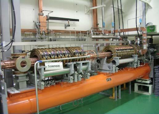
8 PLS-II Linear accelerator Length = 170 m + 86 m 3.0GeV, full energy injection 2,856 MHz (S-band) 10Hz, 0.5 ns, 0.6A pulsed beam Norm. emittance 120µmrad Thermionic Electron Gun 17 Pulse Modulators (200MW, 7.5µs) 17 Klystrons (80 MW, 4µs) 16 Energy Doublers (g=1.5) 46 Accelerating Sections
9 Linac & BTL commissioning (PLS-II) First beam from gun (23 May 2011) 0.8 Our measurement was not a picture of an E-beam profile. It was a picture of a boa constrictor digesting an elephant. 0.6 Current [A] n n 2.0n 3.0n Time [s] Emittance measurement (H/V: 600 nm/ MeV) 7 x 10⁻⁶ Analysis of fit for dataset \sigma_x vs. kl 2.5 x 10⁻⁶ Analysis of fit for dataset sigma_y vs. kl 6 Measured data fit 2 Measured data fit x 2 [m 2 ] 3 y 2 [mm] kl [1/m 2 ] kl [1/m 2 ]

10 Linac & BTL commissioning 3 GeV beam (13 June) Beam at injection (29 June) Linac start Pre-injector start 3 GeV beam Summary Charge 1.2 nc 0.6 nc 0.25 nc 0.2 nc Emittance 150 um 180 um Energy jitter 0.12 %
11 Pre-Injector of PLS-II Linac E-gun Prebuncher Buncher Acc #1 Acc #2 Electron gun Thermionic cathode : Y-824 Y-845 Accelerating voltage : DC 80 kv, = 0.5 Beam pulse length : 250 ps, <1, 2 ~ 40 ns Prebuncher 2856 MHz, re-entrant type standing wave cavity Velocity modulation to cause density modulation Buncher 2856 MHz, travelling wave type of 4 cavities ( = 0.75) Accelerator Columns 2856 MHz, Two normal columns of 3m 1 input coupler + 1 output coupler + 84 cavities), ( = 1)
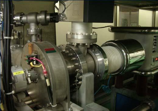
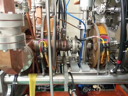
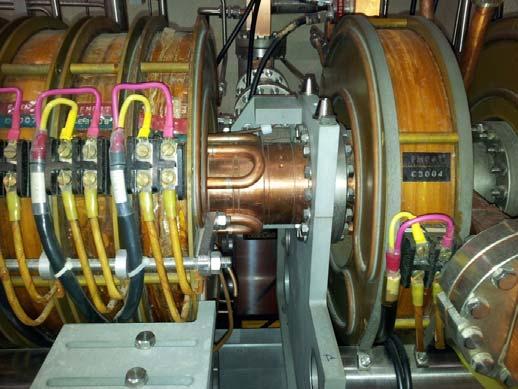
12 Pre-injector Y824 Gun & Magnetic lens ACC1 Input coupler B PB 12
13 Pre-injector Peak current and charge from the gun and after bunching system FCT1 FCT A 1.28 nc 1.7 ns (FWHM) A 0.55 nc Current [A] Current[A] n 25.0n 25.5n 26.0n 26.5n 27.0n 27.5n 28.0n 28.5n Time [s] 24.5n 25.0n 25.5n 26.0n 26.5n 27.0n 27.5n 28.0n 28.5n Time [s] E-gun: Y824 with a <1 ns pulser FCT1: peak current: 0.8 ~1 A, charge: 1~1.3 nc, FWHM: 1.4~1.8 ns FCT2: peak current: 0.4~0.5 A, charge: 500~600 pc Charge loss due to bunching system: 50~60 % Bunch #: 5 (red line), black line is superposition of the 2856 MHz EMI confirmed by BCM6 placing in the middle of Linac 13


![5 kl [1/m 2 ] 0.5 0-0.2 0 0.2 0.4 0.6 0.8 1 1.](/docs-images/85/91545425/images/14-3.jpg "2 kl [1/m 2 ] Quadrupole scan for emittance at the")
14 Pre-injector Beam diagnostics at pre-injector end and BAS1 7 x 10⁻⁶ Analysis of fit for dataset \sigma_x vs. kl 2.5 x 10⁻⁶ Analysis of fit for dataset sigma_y vs. kl 6 Measured data fit 2 Measured data fit 5 x 2 [m 2 ] 4 3 y 2 [mm] kl [1/m 2 ] kl [1/m 2 ] Quadrupole scan for emittance at the Pre-injector Horizontal 115 mm.mrad Vertical 150 mm.mrad 14
15 Linac Efforts for Top-up Injection The linac commissioning was successfully finished on schedule. PLS-II was operated in decay mode during the first year, Radiation level was higher than the limit at the injection point and some undulator beamlines. Beam quality Improvement and monitoring was proved to be urgent and we took some measures to solve this problem. E-gun : Low emittance cathode (Y-824 Y-845) Shorter beam pulse (1 ns 250 ps) Energy feedback system Install slits In-situ energy monitoring Injection angle measurement

 E-gun with")

16 E-gun Cathode : Y824 Y 845 Cathode (Y-824) Cathode (Y-845) E-gun with dual vacuum valves Dual vacuum valve removed
 The streak camera didn t work since too small beam charge per bunch. We used the wideband oscilloscope to get signal from WCM. 800 ps 2012. 07. 28.")
17 Shorter Electron Beam Pulse 2% The high radiation level was partly caused by the bunches which cannot be accommodated in a single SR RF bucket. The grid pulser was changed to shorter one. (1ns 250 ps) The streak camera didn t work since too small beam charge per bunch. We used the wideband oscilloscope to get signal from WCM. 800 ps (a) 1 ns 250 WCM06 Wideband oscilloscope (Agilent 90604A, 6GHz, 20GS/s)
18 Energy Feedback Sytem MK12B Klystron + BPM T02 in dispersive region BPM T02 Stripline BPM Pick-up Libera Single Pass E Layout of Beam Transport Line
19 Energy Feedback Beam energy fluctuation with a period of 80 seconds caused by temporary LCW temperature fluctuation. Energy Feedback Off Energy Feedback On
 ( ) By reducing beta and increasing eta, we can")
20 Slit Installation in BTL (Energy Slit) Energy slit in dispersive region δ = E E o δ1 lower momentum particle δ 0 On momentum particle δ2 Higher momentum particle t or s Slit 2 ( ) ( ) By reducing beta and increasing eta, we can do
 Two vertical slits were installed to reduce the vertical beam size of the injected beam.")
21 Slit Installation in BTL (Emittance Slit) PLS-II LINAC In PLS-II top-up mode, 10 in-vacuum undulators are being operated with small gap (full gap of 6 mm) Two vertical slits were installed to reduce the vertical beam size of the injected beam. y y y Phase advance /2 y ( ) ( ) 2 V slit 2 21

 OTR Monitor (b) OTR Screen (580 nm Al coated on the 25 um")
22 Beam Energy and Energy Spread Monitor A thin film OTR monitor was installed in the dispersion region to monitor the beam energy and the beam energy spread in real time. (a) OTR Monitor (b) OTR Screen (580 nm Al coated on the 25 um polyimide film)

23 OTR Image Analysis Program
24 Top-up Operation of PLS-II Linac Top-up operation for 48 hours Top-up operation for 150 minutes (current band ±0.3%) Injection Charge in the top-up injection (20~30pC)

25 LINAC Beam Stability Pulse-to-pulse beam orbit jitter at 3 GeV Top-up Injection for 1 hr x = 0.15 mm y = 0.11 mm
26 PLS-II LINAC Operation Parameters Parameters Energy [GeV] (max) (3.060) Energy Stability [%] std value Energy Spread [%] 0.05 (in 10 min) 0.10 (in 10 min) Injection Rate (Hz) 10 Injection Charge (pc) 15 ~ 25 Injection Time (sec) 5.5 (avg) Injection Interval (sec) 190 Injection Efficiency (%) 96.0 (avg)
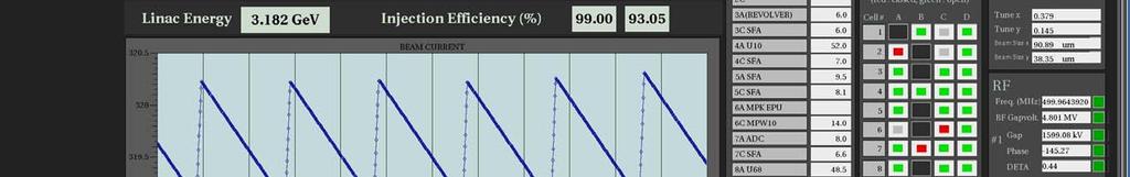
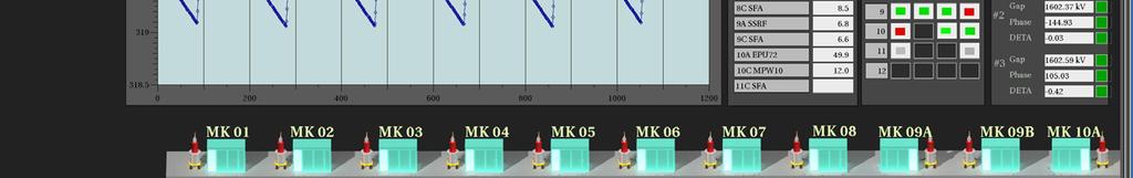
27 PLS-II LINAC Control Panel
28 Linac Automation Process in Normal Status Step 1: orbit measurement - set MPS, RF power and phase, etc Step 2: energy measurement - finding present energy Step 3: achievement maximum energy in given MK power status - Phasing using energy maximization Step 4: set operation energy - measure IPA12B phase-energy relation Step 5: set reference orbit - orbit correction

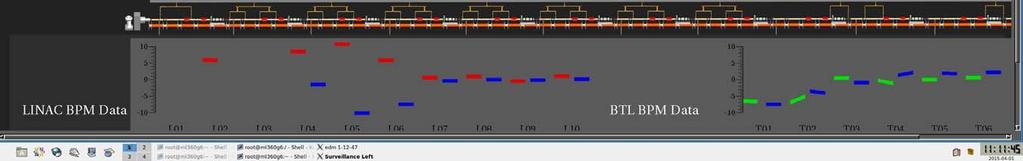
29 PLS-II Injection Monitoring Panel
30 2014 User Service Current & Rate Beam Cuurent (ma) User Service Rate (%) th 5th 6th 7th 8th 9th 10th 11th 12th 13th 14th 15th 16th 17th 18th 19th 20th 21th 22th 23th 24th User Run 70.0
 Time (11220")
31 2014 Fault Report in the User Service ETC 24% PSI 1% Kicker 4% SRF 30% Utility 20% ETC 10% Kicker 2% SRF 30% Utility 3% Control 6% Vacuum 1% Linac 3% Beamline 19% Operation MPS 3% 6% Control 1% Linac 25% Operation Beam line 1% 6% MPS 5% Number (56) Time (11220 min)
, DawonSys(8ea)")
 E37320 (3ea) Phase")
 Cavity Diameter 205")


32 Unit Module of PLS-II Linac V CCPS GA(8ea), DawonSys(8ea) POSCO-ICT(1ea) 200 MW Modulator Toshiba E3712 (14ea) E37320 (3ea) Phase Reference Line Main Drive Line IPA Mode TE015 SLED (16 ea) Cavity Diameter 205 mm Cavity Length mm Q Value 100,000 Coupling Factor 4.8 Power Gain 7.4 db Energy Gain 1.5~1.6 6 M/K modules feed 4 columns 10 ft. Accelerator (46 ea) 11 M/K modules feed 2 columns

 Total Inductance 10.5 μh (1.")
33 200 MW Modulator Two parallel networks of 14 elements of capacitors and inductors Peak Power 200 MW Charging Voltage 50 kv PFN Output Voltage 25 kv PFN Output Current 8.9 ka HV Pulse Width 7.5 μs Repetition Rate 10 pps PFN Impedance 2.7 Ω Total Capacitance 1.4 μf (50 nf x 28) Total Inductance 10.5 μh (1.5 μh x 28) Cabinet Dimension 1600 x 1600 x 2100 (mm 3 )


 Resonant Current <Condition> PRF :")
34 Capacitor Charge Power Supply Specification Average output power : 30kW Peak charging power : 37.5kJ/s Constant DC Power : 50kW Max output voltage : +50kV Max output current : 1.2A Power factor : 0.9 Voltage regulation : <+/- 0.01% Efficiency at full load : >85% 3 phase input voltage : 480Vac/60Hz Cooling water : >5 l/m PFN Voltage(10,000:1) Resonant Current <Condition> PRF : 10Hz Voltage : 40kV Tc : 44.1ms Load : 1.4uF Ec : 31.7kW

35 Modulator Circuit Diagram
 60 Operating Pulse Length (μs) 4.")
36 80 MW Klystron 3 GeV LINAC PLS-II Toshiba E3712 Klystron Toshiba Operation Frequency (MHz) 2,856 Max. Output Power (MW) 80 Max. Average Output Power (kw) 19 Max. Repetition Rate (Hz) 60 Operating Pulse Length (μs) 4.0 Gain (db) 53 Efficiency (%) 42 Number of Cavities 5 Beam Voltage (kv) 400 Beam Current (A) 500 Perveance ( P) 2 36
37 RF system of PLS-II Linac (before 2015) R R C C R SSA LLRF 0 dbm CW 11 V 800 W Peak TTL 5V Timing System 0 dbm CW 2 W CW TTL 5V 2 W Pre-amp. with PSK 2,856 MHz Master Osc. 7/8" Coaxial Phase Reference Line C2 20 db C8 20 db C9A 6 db C12B 6 db s o 180 o 1.1 s RF Phase State Load Prebuncher controller Buncher controller 26.5 db K1 120 kw W/G - Coaxial Cross Coupler C2 16 db IPA K2 1 5/8" Rigid Main Drive Line C8 16 db C9A 10 db C12B 10 db IPA IPA IPA K8 K9A K12B Load 20 db 10 db Attenuator S2 S8 S9A S12B Phase Shifter 3-dB Power Divider 3-dB Power Divider 3-dB PD G P.B BUN. A1 A2 A3 A4 A5 A6 A45 A46

 2015-Apr-08 choij@postech.ac.")
38 Modulator Klystron Fault (2012) Fault number Fault hour Linac Energy Availability : 95.1 % (Energy > 2.97 GeV) 2015-Apr-08 choij@postech.ac.kr 38

 2015-Apr-08 choij@postech.ac.")
39 Modulator Klystron Fault (2013) Fault number Fault hour Linac Energy Availability : 96.1 % (Energy > 2.97 GeV) 2015-Apr-08 choij@postech.ac.kr 39

 2015-Apr-08 choij@postech.ac.")
40 Modulator Klystron Fault (2014) Fault number Fault hour Linac Energy Availability : 96.4 % (Energy > 2.97 GeV) 2015-Apr-08 choij@postech.ac.kr 40
41 Failed Klystron Mod. No Tube Type Serial No. Heater Time(Hr) Removed Problems 1 M02 E3712 PLS001 18, Mag. coil short, Kly. Arc (13kV) 2 M06 E PLS 26, Kly. arc at DC 14kV 3 M08 E PLS 27, Heater internal short 4 M12 E PLS 28, Input cavaty damage 5 M09 E PLS 68, capacitor divider damage 6 M01 SLAC A 72, Heater out of lifetime 7 MK07 E PLS 71, Heater out of lifetime 8 MK11 E PLS 71, Heater out of lifetime 9 MK10 E PLS 72, Heater out of lifetime 10 MK03 E3712 PLS002 80, Heater out of lifetime 11 MK04 E PLS 90, Heater out of lifetime 12 MK05 E PLS 89, Heater out of lifetime 13 MK08 E PLS 62, Tube Collector Water leak 14 MK02 E PLS 78, Heater out of lifetime 15 MK06 E PLS 67, Heater out of lifetime (inner acing) 16 MK12 E PLS-R 40, Heater out of lifetime (Vacuum fault) 17 MK03 E PLS 29, Magnet Coil Cooling Leak 18 Test Linac SLAC A 73, Installed, Window leak 19 MK05 E PLS 35, Internal gun arcing 20 M02 E PLS 31, Tank Pulse Tr breakdown 21 MK09A E PLS Inner acing-no power to Bucking coil ( ) 22 M06 E PLS 35, Internal gun arcing 23 M03 E PLS 7, Cavity degradation 24 M01 SLAC A 45, Tank Pulse Tr breakdown 25 MK12B E PLS 21, gun internal arcing 26 MK02 E Average 48,491

42 Lifetime Status of Failed Klystron (2014/2/5) Lifetime of Failed klystron(hrs) 100,000 90,000 80,000 70,000 60,000 50,000 40,000 30,000 20,000 10, Klystron No. Heater Time(Hr)
 2015-Apr-08 choij@postech.")
43 Operational Status of M/K System (2015/2/3) 2015-Apr-08 43
44 Issues in PLS-II Linac Beam voltage stability improvement - All modulator system was changed from SCR-type to CCPS (August 2014) - High voltage stability less than 50 ppm was achieved leading to improved beam stability. MK 01 LLRF installation - Monitoring RF Phase and RF attenuation in prebuncher and buncher - MK01 Klystron phase feedback. Energy upgrade for stable top-up operation At least 250 MeV required One module already divided, two more modules to be divided. Continue RF conditioning of newly divided module. Replace the accelerator column with MHI. Low energy top-up In case of a klystron fault, the top-up injection energy would be lowered temporarily, 2.7 GeV. Machine study will be done with SR.
45 Issues in PLS-II Linac Minimize the faults of M/K system Add waveguide RF Window. Improve high voltage CCPS cables. Automated operation Reduce dependence of operation on the human labor. Rapid set the optimum acceleration parameters in case of module trouble Diagnostics upgrade Libera BPM (Single Pass E) BTL section already replaced. Beam energy measurement, beam charge, and angle of injected beam Libera BPM s in linac acceleration section (2015) BAS01 beam diagnostics Beam energy and energy spread at pre-injector new bending magnet Emittance measurement at 3 GeV. Beam repetition rate less than 10 Hz For energy saving Requirement: Increase beam transmission rate
46 Issues in PLS-II Linac Improve the energy stability One or two hours of energy drift without energy feedback system. Identify the source of beam energy jitter and drift. Better temperature control Stability of the K&M system Improve top-up injection efficiency Need accurate measurement for the reliability of radiation level in the experimental hall. Calibration of BPM sum value with ICT (Integrating Current Transformer).
47 Energy Status of PLS-II Linac The linac energy was increased by dividing 4 modules to feed two accelerating columns. The linac is in operation with the energy availability larger than 96% (Energy>2.97 GeV). But no energy margin is secured, and top-up operation is in danger in case one module get trouble. Design Operation Mod. # Kly. Power (MW) SLED Gain Energy (MeV) Cumulative Energy (MeV) Acc. Gradient (MV/m) Supplier IHEP IHEP IHEP IHEP , IHEP , IHEP , IHEP , IHEP 4 9A , IHEP 2 9B , IHEP 2 10A , IHEP 2 10B , IHEP 2 11A , IHEP 2 11B , IHEP 2 12A , MHI 2 12B , MHI 2 A/C Mod. # Kly. Power (MW) SLED Gain Energy (MeV) Cumulative Energy (MeV) Acc. Gradient (MV/m) Supplier IHEP IHEP IHEP IHEP , IHEP , IHEP , IHEP , IHEP 4 9A , IHEP 2 9B , IHEP 2 10A , IHEP 2 10B , IHEP 2 11A , IHEP 2 11B , IHEP 2 12A , MHI 2 12B , MHI 2 A/C
48 PLS-II Linac RF system (after 2015) 4.2 s 2 W Pre-amp. with PSK LLRF 2,856 MHz Master Osc. 0 o 180 o 3 dbm CW (with PSK) 2 W CW (w/o PSK) 1.1 s RF Phase State 800 W Peak SSA 26.5 db W/G - Coaxial Cross Coupler K1 120 kw 3 dbm CW (w/o PSK) LLRF SSA C2 20 db C2 16 db IPA C3 15 db C3 12 db IPA 7/8" Coaxial Phase Reference Line 1&5/8 Main Drive Line C9A 6 db C9A 10 db IPA C12B 6 db C12B 6 db IPA Load Load K2A K2B K3 K8 K9A K12B 20 db 10 db Attenuator Phase Shifter G P.B BUN. A1 A2 A3 A4 A5 A6 A7 A8 A9 A10 A31 A32 A45 A46
49 Mod. # Further Energy Upgrade for PLS-II More energy is needed for stable operation of PLS-II Linac in case of K/M module trouble. Three additional modules will be divided to obtain 10 % energy margin. MK02A module was divided last winter. Design Operation Example Kly. Power (MW) SLED Gain Energy (MeV) Cumulative Energy (MeV) Acc. Gradient (MV/m) Supplier IHEP 2 2A IHEP 2 2B IHEP 2 3A IHEP 2 3B IHEP 2 4A IHEP 2 4B IHEP IHEP IHEP IHEP IHEP 4 9A IHEP 2 9B IHEP 2 10A IHEP 2 10B IHEP 2 11A IHEP 2 11B IHEP 2 12A MHI 2 12B MHI 2 A/C Mod. # Kly. Power (MW) SLED Gain Energy (MeV) Cumulative Energy (MeV) Acc. Gradient (MV/m) Supplier IHEP 2 2A IHEP 2 2B IHEP IHEP IHEP IHEP IHEP IHEP IHEP 4 9A IHEP 2 9B IHEP 2 10A IHEP 2 10B IHEP 2 11A IHEP 2 11B IHEP 2 12A MHI 2 12B MHI 2 A/C
50 S-band High power TE012 mode RF Window Reduce the recovery time in case of klystron fault less than one day. MK01 MK08 : No RF Window MK09A MK12B : Double Window System Develop the Single RF window and attach it after Klystron combiner. Engineering design is in progress. Present RF Window (MK09A, MK10A MK12A) Planned RF Window
51 Long-term Plan Increase beam energy Lengthen the accelerator length to accommodate additional accelerator columns. lump-sum budget required. Use C-band accelerator columns (?) The higher accelerating gradient : ~ 40 MV/m Pre-injector upgrade (E-beam quality upgrade) Thermionic gun => Photo-cathode gun, or Increase E-gun voltage from 80 kev to ~200 kev Option for single bunch acceleration
52 Agenda for this visit Operation Related Phasing method and algorithm Trajectory correction scheme Energy feedback Recovery scheme in case of M/K module fault Short and long-term energy stability Beam / Machine parameter taking and management Machine start-up and Top-up operation DB generation and management on beam and machine parameters. Review parameter history Top-up related discussion (need to contact a PF person in charge) Injection efficiency measurement method Injection optics management injection angle etc. Injection scheme Injection perturbation and cure
53 Agenda for this visit Linac Machine related High-power RF Klystron output power measurement SLED gain measurement RF Phase Feedback : Klystron or SLED Phase change speed Modulator high voltage cable issue Termination design for reducing HV breakdown Cooling and Gallery air conditioning Radiation level regulation (injection point and experimental hall) Technical cooperation using video conference


54 PLS-II Linac Members B.-J. Lee Klystron & Test Lab J.- Y. Choi Team Leader Diagnostics S. D. Jang Modulator System Y. K. Sohn E-gun, Kicker Modulator W.H. Hwang RF system J. K. Oh Maintenance
55 Thank for very much for your attention!
Detailed Design Report
 Detailed Design Report Chapter 4 MAX IV Injector 4.6. Acceleration MAX IV Facility CHAPTER 4.6. ACCELERATION 1(10) 4.6. Acceleration 4.6. Acceleration...2 4.6.1. RF Units... 2 4.6.2. Accelerator Units...
Current status of XFEL/SPring-8 project and SCSS test accelerator
 Current status of XFEL/SPring-8 project and SCSS test accelerator Takahiro Inagaki for XFEL project in SPring-8 inagaki@spring8.or.jp Outline (1) Introduction (2) Key technology for compactness (3) Key
Diamond RF Status (RF Activities at Daresbury) Mike Dykes
 Mike Dykes") Diamond RF Status (RF Activities at Daresbury) Mike Dykes ASTeC What is it? What does it do? Diamond Status Linac Booster RF Storage Ring RF Summary Content ASTeC ASTeC was formed in 2001 as a centre of
Diamond RF Status (RF Activities at Daresbury) Mike Dykes ASTeC What is it? What does it do? Diamond Status Linac Booster RF Storage Ring RF Summary Content ASTeC ASTeC was formed in 2001 as a centre of
The Elettra Storage Ring and Top-Up Operation
 The Elettra Storage Ring and Top-Up Operation Emanuel Karantzoulis Past and Present Configurations 1994-2007 From 2008 5000 hours /year to the users 2010: Operations transition year Decay mode, 2 GeV (340mA)
Status of RF Power and Acceleration of the MAX IV - LINAC
 Status of RF Power and Acceleration of the MAX IV - LINAC Dionis Kumbaro ESLS RF Workshop 2015 MAX IV Laboratory A National Laboratory for synchrotron radiation at Lunds University 1981 MAX-lab is formed
Present Status and Future Upgrade of KEKB Injector Linac
 Present Status and Future Upgrade of KEKB Injector Linac Kazuro Furukawa, for e /e + Linac Group Present Status Upgrade in the Near Future R&D towards SuperKEKB 1 Machine Features Present Status and Future
4.4 Injector Linear Accelerator
 4.4 Injector Linear Accelerator 100 MeV S-band linear accelerator based on the components already built for the S-Band Linear Collider Test Facility at DESY [1, 2] will be used as an injector for the CANDLE
XFEL High Power RF System Recent Developments
 XFEL High Power RF System Recent Developments for the XFEL RF Group Outline XFEL RF System Requirements Overview Basic Layout RF System Main Components Multibeam Klystrons Modulator RF Waveguide Distribution
INFN School on Electron Accelerators. RF Power Sources and Distribution
 INFN School on Electron Accelerators 12-14 September 2007, INFN Sezione di Pisa Lecture 7b RF Power Sources and Distribution Carlo Pagani University of Milano INFN Milano-LASA & GDE The ILC Double Tunnel
KEKB INJECTOR LINAC AND UPGRADE FOR SUPERKEKB
 KEKB INJECTOR LINAC AND UPGRADE FOR SUPERKEKB S. Michizono for the KEK electron/positron Injector Linac and the Linac Commissioning Group KEK KEKB injector linac Brief history of the KEK electron linac
RF Power Generation II
 RF Power Generation II Klystrons, Magnetrons and Gyrotrons Professor R.G. Carter Engineering Department, Lancaster University, U.K. and The Cockcroft Institute of Accelerator Science and Technology Scope
IOT OPERATIONAL EXPERIENCE ON ALICE AND EMMA AT DARESBURY LABORATORY
 IOT OPERATIONAL EXPERIENCE ON ALICE AND EMMA AT DARESBURY LABORATORY A. Wheelhouse ASTeC, STFC Daresbury Laboratory ESLS XVIII Workshop, ELLETRA 25 th 26 th November 2010 Contents Brief Description ALICE
RF considerations for SwissFEL
 RF considerations for H. Fitze in behalf of the PSI RF group Workshop on Compact X-Ray Free Electron Lasers 19.-21. July 2010, Shanghai Agenda Introduction RF-Gun Development C-band development Summary
The PEFP 20-MeV Proton Linear Accelerator
 Journal of the Korean Physical Society, Vol. 52, No. 3, March 2008, pp. 721726 Review Articles The PEFP 20-MeV Proton Linear Accelerator Y. S. Cho, H. J. Kwon, J. H. Jang, H. S. Kim, K. T. Seol, D. I.
CLIC Feasibility Demonstration at CTF3
 CLIC Feasibility Demonstration at CTF3 Roger Ruber Uppsala University, Sweden, for the CLIC/CTF3 Collaboration http://cern.ch/clic-study LINAC 10 MO303 13 Sep 2010 The Key to CLIC Efficiency NC Linac for
Experience with the Cornell ERL Injector SRF Cryomodule during High Beam Current Operation
 Experience with the Cornell ERL Injector SRF Cryomodule during High Beam Current Operation Matthias Liepe Assistant Professor of Physics Cornell University Experience with the Cornell ERL Injector SRF
Spear3 RF System Sam Park 11/06/2003. Spear3 RF System. High Power Components Operation and Control. RF Requirement.
 Spear3 RF System RF Requirement Overall System High Power Components Operation and Control SPEAR 3 History 1996 Low emittance lattices explored 1996 SPEAR 3 proposed 11/97 SPEAR 3 design study team formed
PULSED MODULATOR TECHNOLOGY
 PULSED MODULATOR TECHNOLOGY Hiroshi MATSUMOTO J-PARC/KEK CONTENTS 1. VARIOUS REQUIREMENT OF THE RECENT MODULATORS SHORT PULSE WIDTH (~µsec) LONG PULSE WIDTH (~msec) AND HIGH REP. RATE. (200 Hz) OUTPUT
The basic parameters of the pre-injector are listed in the Table below. 100 MeV
 3.3 The Pre-injector The high design brightness of the SLS requires very high phase space density of the stored electrons, leading to a comparatively short lifetime of the beam in the storage ring. This,
Linac upgrade plan using a C-band system for SuperKEKB
 Linac upgrade plan using a C-band system for SuperKEKB S. Fukuda, M. Akemono, M. Ikeda, T. Oogoe, T. Ohsawa, Y. Ogawa, K. Kakihara, H. Katagiri, T. Kamitani, M. Sato, T. Shidara, A. Shirakawa, T. Sugimura,
30 GHz Power Production / Beam Line
 30 GHz Power Production / Beam Line Motivation & Requirements Layout Power mode operation vs. nominal parameters Beam optics Achieved performance Problems Beam phase switch for 30 GHz pulse compression
Status of CTF3. G.Geschonke CERN, AB
 Status of CTF3 G.Geschonke CERN, AB CTF3 layout CTF3 - Test of Drive Beam Generation, Acceleration & RF Multiplication by a factor 10 Drive Beam Injector ~ 50 m 3.5 A - 2100 b of 2.33 nc 150 MeV - 1.4
Evaluation of Performance, Reliability, and Risk for High Peak Power RF Sources from S-band through X-band for Advanced Accelerator Applications
 Evaluation of Performance, Reliability, and Risk for High Peak Power RF Sources from S-band through X-band for Advanced Accelerator Applications Michael V. Fazio C. Adolphsen, A. Jensen, C. Pearson, D.
Status of Elettra, top-up and other upgrades
 Status of Elettra, top-up and other upgrades Emanuel Karantzoulis ELETTRA / Trieste, Italy / 2010 November 25-26 Past and Present Configurations 1994-2007 From 2008 No full energy injection Full energy
STATUS OF THE SWISSFEL C-BAND LINEAR ACCELERATOR
 Proceedings of FEL213, New York, NY, USA STATUS OF THE SWISSFEL C-BAND LINEAR ACCELERATOR F. Loehl, J. Alex, H. Blumer, M. Bopp, H. Braun, A. Citterio, U. Ellenberger, H. Fitze, H. Joehri, T. Kleeb, L.
Status of SOLARIS. Paweł Borowiec On behalf of Solaris Team
 Status of SOLARIS Paweł Borowiec On behalf of Solaris Team e-mail: pawel.borowiec@uj.edu.pl XX ESLS-RF Meeting, Villingen 16-17.11.2016 Outline 1. Timeline 2. Injector 3. Storage ring 16-17.11.2016 XX
Operational experience with the SOLEIL LINAC and Status of the ThomX LINAC project
 Operational experience with the SOLEIL LINAC and Status of the ThomX LINAC project 16/11/2016 20th ELS-RF Workshop Pollina JP 1 and Status of the ThomX LINAC project Operational experience with the SOLEIL
Activities on FEL Development and Application at Kyoto University
 Activities on FEL Development and Application at Kyoto University China-Korea-Japan Joint Workshop on Electron / Photon Sources and Applications Dec. 2-3, 2010 @ SINAP, Shanghai Kai Masuda Inst. Advanced
LCLS RF Reference and Control R. Akre Last Update Sector 0 RF and Timing Systems
 LCLS RF Reference and Control R. Akre Last Update 5-19-04 Sector 0 RF and Timing Systems The reference system for the RF and timing starts at the 476MHz Master Oscillator, figure 1. Figure 1. Front end
ANKA RF System - Upgrade Strategies
 ANKA RF System - Upgrade Strategies Vitali Judin ANKA Synchrotron Radiation Facility 2014-09 - 17 KIT University of the State Baden-Wuerttemberg and National Laboratory of the Helmholtz Association www.kit.edu
Status of BESSY II and berlinpro. Wolfgang Anders. Helmholtz-Zentrum Berlin for Materials and Energy (HZB) 20th ESLS-RF Meeting
 20th ESLS-RF Meeting") Status of BESSY II and berlinpro Wolfgang Anders Helmholtz-Zentrum Berlin for Materials and Energy (HZB) 20th ESLS-RF Meeting 16.-17.11.2016 at PSI Outline BESSY II Problems with circulators Landau cavity
Status of BESSY II and berlinpro Wolfgang Anders Helmholtz-Zentrum Berlin for Materials and Energy (HZB) 20th ESLS-RF Meeting 16.-17.11.2016 at PSI Outline BESSY II Problems with circulators Landau cavity
First Simultaneous Top-up Operation of Three Different Rings in KEK Injector Linac
 First Simultaneous Top-up Operation of Three Different Rings in KEK Injector Linac Masanori Satoh (Acc. Lab., KEK) for the injector upgrade group 2010/9/16 1 Overview of Linac Beam Operation 2010/9/16
RF plans for ESS. Morten Jensen. ESLS-RF 2013 Berlin
 RF plans for ESS Morten Jensen ESLS-RF 2013 Berlin Overview The European Spallation Source (ESS) will house the most powerful proton linac ever built. The average beam power will be 5 MW which is five
PEP II Design Outline
 PEP II Design Outline Balša Terzić Jefferson Lab Collider Review Retreat, February 24, 2010 Outline General Information Parameter list (and evolution), initial design, upgrades Collider Ring Layout, insertions,
Design and Simulation of High Power RF Modulated Triode Electron Gun. A. Poursaleh
 Design and Simulation of High Power RF Modulated Triode Electron Gun A. Poursaleh National Academy of Sciences of Armenia, Institute of Radio Physics & Electronics, Yerevan, Armenia poursaleh83@yahoo.com
A HIGH POWER LONG PULSE HIGH EFFICIENCY MULTI BEAM KLYSTRON
 A HIGH POWER LONG PULSE HIGH EFFICIENCY MULTI BEAM KLYSTRON A.Beunas and G. Faillon Thales Electron Devices, Vélizy, France S. Choroba DESY, Hamburg, Germany Abstract THALES ELECTRON DEVICES has developed
Status of SOLARIS Arkadiusz Kisiel
 Status of SOLARIS Arkadiusz Kisiel Solaris National Synchrotron Light Source Jagiellonian University Czerwone Maki 98 30-392 Kraków www.synchrotron.uj.edu.pl Arkadiusz.Kisiel@uj.edu.pl On behalf of SOLARIS
Digital BPMs and Orbit Feedback Systems
 Digital BPMs and Orbit Feedback Systems, M. Böge, M. Dehler, B. Keil, P. Pollet, V. Schlott Outline stability requirements at SLS storage ring digital beam position monitors (DBPM) SLS global fast orbit
THE NEXT LINEAR COLLIDER TEST ACCELERATOR: STATUS AND RESULTS * Abstract
 SLAC PUB 7246 June 996 THE NEXT LINEAR COLLIDER TEST ACCELERATOR: STATUS AND RESULTS * Ronald D. Ruth, SLAC, Stanford, CA, USA Abstract At SLAC, we are pursuing the design of a Next Linear Collider (NLC)
3 cerl. 3-1 cerl Overview. 3-2 High-brightness DC Photocathode Gun and Gun Test Beamline
 3 cerl 3-1 cerl Overview As described before, the aim of the cerl in the R&D program includes the development of critical components for the ERL, as well as the construction of a test accelerator. The
KARA and FLUTE RF Overview/status
 KARA and FLUTE RF Overview/status Nigel Smale on behalf of IBPT and LAS teams Laboratory for Applications of Synchrotron radiation (LAS) Institute for Beam Physics and Technology (IBPT) KARA KIT The Research
SPEAR 3: Operations Update and Impact of Top-Off Injection
 SPEAR 3: Operations Update and Impact of Top-Off Injection R. Hettel for the SSRL ASD 2005 SSRL Users Meeting October 18, 2005 SPEAR 3 Operations Update and Development Plans Highlights of 2005 SPEAR 3
CEBAF Accelerator Update. Michael Tiefenback CASA Accelerator Physics Experimental Liaison June 14, 2017
 CEBAF Accelerator Update Michael Tiefenback CASA Accelerator Physics Experimental Liaison June 14, 2017 CLAS12 Collaboration Meeting, June 13-16, 2017 1 Accelerator Division Leadership On April 30 Andrew
A New 4MW LHCD System for EAST
 1 EXW/P7-29 A New 4MW LHCD System for EAST Jiafang SHAN 1), Yong YANG 1), Fukun LIU 1), Lianmin ZHAO 1) and LHCD Team 1) 1) Institute of Plasma Physics, Chinese Academy of Sciences, Hefei, China E-mail
P. Emma, et al. LCLS Operations Lectures
 P. Emma, et al. LCLS Operations Lectures LCLS 1 LCLS Accelerator Schematic 6 MeV 135 MeV 250 MeV σ z 0.83 mm σ z 0.83 mm σ z 0.19 mm σ δ 0.05 % σ δ 0.10 % σ δ 1.6 % Linac-0 L =6 m rf gun L0-a,b Linac-1
SRS and ERLP developments. Andrew moss
 SRS and ERLP developments Andrew moss Contents SRS Status Latest news Major faults Status Energy Recovery Linac Prototype Latest news Status of the RF system Status of the cryogenic system SRS Status Machine
DESIGN AND PERFORMANCE OF L-BAND AND S-BAND MULTI BEAM KLYSTRONS
 DESIGN AND PERFORMANCE OF L-BAND AND S-BAND MULTI BEAM KLYSTRONS Y. H. Chin, KEK, Tsukuba, Japan. Abstract Recently, there has been a rising international interest in multi-beam klystrons (MBK) in the
Pulsed Klystrons for Next Generation Neutron Sources Edward L. Eisen - CPI, Inc. Palo Alto, CA, USA
 Pulsed Klystrons for Next Generation Neutron Sources Edward L. Eisen - CPI, Inc. Palo Alto, CA, USA Abstract The U.S. Department of Energy (DOE) Office of Science has funded the construction of a new accelerator-based
RF Upgrades & Experience At JLab. Rick Nelson
 RF Upgrades & Experience At JLab Rick Nelson Outline Background: CEBAF / Jefferson Lab History, upgrade requirements & decisions Progress & problems along the way Present status Future directions & concerns
FIRST SIMULTANEOUS TOP-UP OPERATION OF THREE DIFFERENT RINGS IN KEK INJECTOR LINAC
 FIRST SIMULTANEOUS TOP-UP OPERATION OF THREE DIFFERENT RINGS IN KEK INJECTOR LINAC M. Satoh #, for the IUC * Accelerator Laboratory, High Energy Accelerator Research Organization (KEK) 1-1 Oho, Tsukuba,
The Construction Status of CSNS Linac
 The Construction Status of CSNS Linac Sheng Wang Dongguan branch, Institute of High Energy Physics, CAS Sep.2, 2014, Geneva Outline The introduction to CSNS accelerators The commissoning of ion source
Operating Experience and Reliability Improvements on the 5 kw CW Klystron at Jefferson Lab
 Operating Experience and Reliability Improvements on the 5 kw CW Klystron at Jefferson Lab Richard Walker & Richard Nelson Jefferson Lab, Newport News VA Jefferson Lab is a $600M Department of Energy facility
TWO BUNCHES WITH NS-SEPARATION WITH LCLS*
 TWO BUNCHES WITH NS-SEPARATION WITH LCLS* F.-J. Decker, S. Gilevich, Z. Huang, H. Loos, A. Marinelli, C.A. Stan, J.L. Turner, Z. van Hoover, S. Vetter, SLAC, Menlo Park, CA 94025, USA Abstract The Linac
Introduction: CW SRF linac types, requirements and challenges High power RF system architecture
 RF systems for CW SRF linacs S. Belomestnykh Cornell University Laboratory for Elementary-Particle Physics LINAC08, Victoria, Canada October 1, 2008 Outline L band Introduction: CW SRF linac types, requirements
Screen investigations for low energetic electron beams at PITZ
 1 Screen investigations for low energetic electron beams at PITZ S. Rimjaem, J. Bähr, H.J. Grabosch, M. Groß Contents Review of PITZ setup Screens and beam profile monitors at PITZ Test results Summary
reported by T. Shintake KEK / RIKEN Japan Summary of C-band R&D for Linear Collider at KEK New soft-x-ray FEL Project at RIKEN/SPring-8
 C-band RF System R&D reported by T. Shintake KEK / RIKEN Japan Summary of C-band R&D for Linear Collider at KEK New soft-x-ray FEL Project at RIKEN/SPring-8 Project was funded in 2001 April Material Science
Proton Engineering Frontier Project
 Proton Engineering Frontier Project OECD Nuclear Energy Agency Fifth International Workshop on the Utilisation and Reliability of High Power Proton Accelerators (HPPA5) (6-9 May 2007, Mol, Belgium) Yong-Sub
5 Project Costs and Schedule
 93 5 Project Costs and Schedule 5.1 Overview The cost evaluation for the integrated version of the XFEL with 30 experiments and 35 GeV beam energy as described in the TDR-2001 yielded 673 million EUR for
Next Linear Collider. The 8-Pack Project. 8-Pack Project. Four 50 MW XL4 X-band klystrons installed on the 8-Pack
 The Four 50 MW XL4 X-band klystrons installed on the 8-Pack The Demonstrate an NLC power source Two Phases: 8-Pack Phase-1 (current): Multi-moded SLED II power compression Produce NLC baseline power: 475
High Brightness Injector Development and ERL Planning at Cornell. Charlie Sinclair Cornell University Laboratory for Elementary-Particle Physics
 High Brightness Injector Development and ERL Planning at Cornell Charlie Sinclair Cornell University Laboratory for Elementary-Particle Physics June 22, 2006 JLab CASA Seminar 2 Background During 2000-2001,
The FLASH objective: SASE between 60 and 13 nm
 Injector beam control studies winter 2006/07 talk from E. Vogel on work performed by W. Cichalewski, C. Gerth, W. Jalmuzna,W. Koprek, F. Löhl, D. Noelle, P. Pucyk, H. Schlarb, T. Traber, E. Vogel, FLASH
Trigger-timing signal distribution system for the KEK electron/positron injector linac
 Trigger-timing signal distribution system for the KEK electron/positron injector linac T. Suwada, 1 K. Furukawa, N. Kamikubota, and M. Satoh, Accelerator Laboratory, High Energy Accelerator Research Organization
Solid State Modulators for X-Band Accelerators
 Solid State Modulators for X-Band Accelerators John Kinross-Wright Diversified Technologies, Inc. Bedford, Massachusetts DTI X-Band Experience Developed and built two completely different NLC-class modulator
Towards an X-Band Power Source at CERN and a European Structure Test Facility
 Towards an X-Band Power Source at CERN and a European Structure Test Facility Erk Jensen and Gerry McMomagle CERN The X-Band Accelerating Structure Design and Test-Program Workshop Day 2: Structure Testing
Photo cathode RF gun -
 Photo cathode RF gun - *),,, ( 05 Nov. 2004 Spring8 UTNL Linac & Mg Photocathode RF Gun Mg photocathode NERL, 18 MeV Linac and the RF gun Electron Beam Mg photocathode Mg photocathode RF gun of SPring8
New Filling Pattern for SLS-FEMTO
 SLS-TME-TA-2009-0317 July 14, 2009 New Filling Pattern for SLS-FEMTO Natalia Prado de Abreu, Paul Beaud, Gerhard Ingold and Andreas Streun Paul Scherrer Institut, CH-5232 Villigen PSI, Switzerland A new
CLIC Feasibility Demonstration at CTF3
 CLIC Feasibility Demonstration at CTF3 Roger Ruber Uppsala University, Sweden, KVI Groningen 20 Sep 2011 The Key to CLIC Efficiency NC Linac for 1.5 TeV/beam accelerating gradient: 100 MV/m RF frequency:
Future Performance of the LCLS
 Future Performance of the LCLS J. Welch for many* SLAC National Accelerator Laboratory FLS 2010, ICFA Beam Dynamics Workshop on Future Light Sources, March 1-5, 2010. SLAC National Accelerator Laboratory,
The LEP Superconducting RF System
 The LEP Superconducting RF System K. Hübner* for the LEP RF Group CERN The basic components and the layout of the LEP rf system for the year 2000 are presented. The superconducting system consisted of
STATUS OF THE SwissFEL C-BAND LINAC
 STATUS OF THE SwissFEL C-BAND LINAC F. Loehl, J. Alex, H. Blumer, M. Bopp, H. Braun, A. Citterio, U. Ellenberger, H. Fitze, H. Joehri, T. Kleeb, L. Paly, J.-Y. Raguin, L. Schulz, R. Zennaro, C. Zumbach,
Status of the X-ray FEL control system at SPring-8
 Status of the X-ray FEL control system at SPring-8 T.Fukui 1, T.Hirono 2, N.Hosoda 1, M.Ishii 2, M.Kitamura 1 H.Maesaka 1,T.Masuda 2, T.Matsushita 2, T.Ohata 2, Y.Otake 1, K.Shirasawa 1,M.Takeuchi 2, R.Tanaka
Jefferson Lab Experience with Beam Halo, Beam Loss, etc.
 Jefferson Lab Experience with Beam Halo, Beam Loss, etc. Pavel Evtushenko with a lot of input from many experienced colleagues Steve Benson, Dave Douglas, Kevin Jordan, Carlos Hernandez-Garcia, Dan Sexton,
Tutorial: Trak design of an electron injector for a coupled-cavity linear accelerator
 Tutorial: Trak design of an electron injector for a coupled-cavity linear accelerator Stanley Humphries, Copyright 2012 Field Precision PO Box 13595, Albuquerque, NM 87192 U.S.A. Telephone: +1-505-220-3975
Summary of the 1 st Beam Line Review Meeting Injector ( )
") Summary of the 1 st Beam Line Review Meeting Injector (23.10.2006) 15.11.2006 Review the status of: beam dynamics understanding and simulations completeness of beam line description conceptual design of
Summary of the 1 st Beam Line Review Meeting Injector (23.10.2006) 15.11.2006 Review the status of: beam dynamics understanding and simulations completeness of beam line description conceptual design of
The ESS Accelerator. For Norwegian Industry and Research. Oslo, 24 Sept Håkan Danared Deputy Head Accelerator Division Group Leader Beam Physics
 The ESS Accelerator For Norwegian Industry and Research Oslo, 24 Sept 2013 Håkan Danared Deputy Head Accelerator Division Group Leader Beam Physics The Hadron Intensity Frontier Courtesy of M. Seidel (PSI)
Dark current and multipacting trajectories simulations for the RF Photo Gun at PITZ
 Dark current and multipacting trajectories simulations for the RF Photo Gun at PITZ Introduction The PITZ RF Photo Gun Field simulations Dark current simulations Multipacting simulations Summary Igor Isaev
North Damping Ring RF
 North Damping Ring RF North Damping Ring RF Outline Overview High Power RF HVPS Klystron & Klystron EPICS controls Cavities & Cavity Feedback SCP diagnostics & displays FACET-specific LLRF LLRF distribution
CERN EUROPEAN ORGANIZATION FOR NUCLEAR RESEARCH. A 50 Hz LOW-POWER SOLID-STATE KLYSTRON-MODULATOR
 CERN EUROPEAN ORGANIZATION FOR NUCLEAR REEARCH CTF3 Note 051(Tech.) (IGCT witch) A 50 Hz LOW-POWER OLID-TATE KLYTRON-MODULATOR P. Pearce, L. ermeus, L. hen Abstract A solid-state klystron-modulator has
SLS RF operation report 2003
 SLS RF operation report 2003 M. Pedrozzi, Jean-Yves Raguin Paul Scherrer Institute, 5232 Villigen PSI, Switzerland SUMMARY LINAC report SR Superconducting Third Harmonic system report SR 500 MHz system
Top-Up Experience at SPEAR3
 Top-Up Experience at SPEAR3 Contents SPEAR 3 and the injector Top-up requirements Hardware systems and modifications Safety systems & injected beam tracking Interlocks & Diagnostics SPEAR3 Accelerator
The ALS RF systems, upgrades and ALS-U plans
 The ALS RF systems, upgrades and ALS-U plans M. Betz*, K. Baptiste, Q. Du, M. Vinco, S. Virostek 06/27/2018, CWRF2018, Hsinchu, Taiwan * mbetz@lbl.gov Outline Structure of this talk RF systems in the Advanced
Linac3 experience for LHC ion runs
 Linac3 experience for LHC ion runs G Bellodi for the Linac3 team Keywords: beam performance reliability set up time results of MDs remaining unknowns 1 A year in perspective Source removed: change of main
Status of KEK X-band Test Facility and its future plans
 Status of KEK X-band Test Facility and its future plans Shuji Matsumoto Accelerator Lab., KEK 5/30/2007 US High Field Gradient Collaboration Workshop, SLAC. 1 Contents The New X-band Test Facility (XTF)
X-Band Klystron Development at
 X-Band Klystron Development at SLAC Slide 1 The Beginning X-band klystron work began at SLAC in the mid to late 80 s to develop high frequency (4x SLAC s-band), high power RF sources for the linear collider
Pulses inside the pulse mode of operation at RF Gun
 Pulses inside the pulse mode of operation at RF Gun V. Vogel, V. Ayvazyan, K. Floettmann, D. Lipka, P. Morozov, H. Schlarb, S. Schreiber FLASH Seminar, DESY March 29, 2011 Contents Why we need a PiPmode
2 Work Package and Work Unit descriptions. 2.8 WP8: RF Systems (R. Ruber, Uppsala)
") 2 Work Package and Work Unit descriptions 2.8 WP8: RF Systems (R. Ruber, Uppsala) The RF systems work package (WP) addresses the design and development of the RF power generation, control and distribution
2 Work Package and Work Unit descriptions 2.8 WP8: RF Systems (R. Ruber, Uppsala) The RF systems work package (WP) addresses the design and development of the RF power generation, control and distribution
L-Band RF R&D. SLAC DOE Review June 15 th, Chris Adolphsen SLAC
 L-Band RF R&D SLAC DOE Review June 15 th, 2005 Chris Adolphsen SLAC International Linear Collider (ILC) RF Unit (TESLA TDR Layout) Gradient = 23.4 MV/m Bunch Spacing = 337 ns Fill Time = 420 µs Train Length
Design Studies For The LCLS 120 Hz RF Gun Injector
 BNL-67922 Informal Report LCLS-TN-01-3 Design Studies For The LCLS 120 Hz RF Gun Injector X.J. Wang, M. Babzien, I. Ben-Zvi, X.Y. Chang, S. Pjerov, and M. Woodle National Synchrotron Light Source Brookhaven
An Overview of Beam Diagnostic and Control Systems for AREAL Linac
 An Overview of Beam Diagnostic and Control Systems for AREAL Linac Presenter G. Amatuni Ultrafast Beams and Applications 04-07 July 2017, CANDLE, Armenia Contents: 1. Current status of existing diagnostic
DEVELOPMENT OF A 10 MW SHEET BEAM KLYSTRON FOR THE ILC*
 DEVELOPMENT OF A 10 MW SHEET BEAM KLYSTRON FOR THE ILC* D. Sprehn, E. Jongewaard, A. Haase, A. Jensen, D. Martin, SLAC National Accelerator Laboratory, Menlo Park, CA 94020, U.S.A. A. Burke, SAIC, San
J/NLC Progress on R1 and R2 Issues. Chris Adolphsen
 J/NLC Progress on R1 and R2 Issues Chris Adolphsen Charge to the International Linear Collider Technical Review Committee (ILC-TRC) To assess the present technical status of the four LC designs at hand,
RUNNING EXPERIENCE OF FZD SRF PHOTOINJECTOR
 RUNNING EXPERIENCE OF FZD SRF PHOTOINJECTOR Rong Xiang On behalf of the BESSY-DESY-FZD-MBI collaboration and the ELBE team FEL 2009, Liverpool, United Kingdom, August 23 ~ 28, 2009 Outline Introduction
Oak Ridge Spallation Neutron Source Proton Power Upgrade Project and Second Target Station Project
 Oak Ridge Spallation Neutron Source Proton Power Upgrade Project and Second Target Station Project Workshop on the future and next generation capabilities of accelerator driven neutron and muon sources
TTF / VUV-FEL. Schedule 2005 and Project Management Issues. Schedule 2005 Project Organisation Budget & Controlling
 TTF / VUV-FEL Schedule 200 and Project Management Issues Schedule 200 Project Organisation Budget & Controlling Hans Weise / DESY DESY MAC Meeting November 9th, 2004 TTF Linac Start-up After Final Installation
DELIVERY RECORD. Location: Ibaraki, Japan
 DELIVERY RECORD Client: Japan Atomic Energy Agency (JAEA) High Energy Accelerator Research Organization (KEK) Facility: J-PARC (Japan Proton Accelerator Research Complex) Location: Ibaraki, Japan 1 October
The TESLA RF System. S. Choroba. for the TESLA Collaboration. DESY Notkestr. 85, D Hamburg, Germany
 The TESLA RF System S. Choroba for the TESLA Collaboration DESY Notkestr. 85, D-22603 Hamburg, Germany Abstract. The TESLA project proposed by the TESLA collaboration in 2001 is a 500 to 800GeV e+/e- linear
SUMMARY OF THE ILC R&D AND DESIGN
 SUMMARY OF THE ILC R&D AND DESIGN B. C. Barish, California Institute of Technology, USA Abstract The International Linear Collider (ILC) is a linear electron-positron collider based on 1.3 GHz superconducting
Upgrading LHC Luminosity
 1 Upgrading LHC Luminosity 2 Luminosity (cm -2 s -1 ) Present (2011) ~2 x10 33 Beam intensity @ injection (*) Nominal (2015?) 1 x 10 34 1.1 x10 11 Upgraded (2021?) ~5 x10 34 ~2.4 x10 11 (*) protons per
PRESENT STATUS OF J-PARC
 PRESENT STATUS OF J-PARC # F. Naito, KEK, Tsukuba, Japan Abstract Japan Proton Accelerator Research Complex (J-PARC) is the scientific facility with the high-intensity proton accelerator aiming to realize
LLRF at SSRF. Yubin Zhao
 LLRF at SSRF Yubin Zhao 2017.10.16 contents SSRF RF operation status Proton therapy LLRF Third harmonic cavity LLRF Three LINAC LLRF Hard X FEL LLRF (future project ) Trip statistics of RF system Trip