reported by T. Shintake KEK / RIKEN Japan Summary of C-band R&D for Linear Collider at KEK New soft-x-ray FEL Project at RIKEN/SPring-8
|
|
|
- Dorcas Watts
- 6 years ago
- Views:
Transcription
1 C-band RF System R&D reported by T. Shintake KEK / RIKEN Japan Summary of C-band R&D for Linear Collider at KEK New soft-x-ray FEL Project at RIKEN/SPring-8 Project was funded in 2001 April Material Science Program at RIKEN Multi-laboratory joint project (SPring-8, RIKEN, KEK,,,,).String Test for C-band RF System for Linear Collider Presented at 9th International Workshop on Linear Collider (LC02) at SLAC Stanford University, Feb. 2002


2 C-band R&D JLC C-band (5712 MHz) Main Linac Tunnel Granite: stable ground RF Pulse compressor 50 MW x 2 Klystron gallery Diameter: 3.0 m Diameter: 4.2 m Active Length: 14 km RF pulse compressor klystrons 50 MW 2.5 µsec 36 MV/m Gain: x 3.5 Conventional wave-guide system BPMs 36 MV/m (45 MV/m) 8m Accelerator 1.8 m each beam
3


4 Phase-I R&D Summary C-band R&D C-band Klystron 50MW, OK 2.5 µsec, 47 % Life test >5000 hour, OK. Klystron Modulator 110 MW 100 pps Smart modulator using inverter HV charger. OK Running for klystron life test. RF Pulse Compressor Flat Pulse Gain 3.3 Three-cell cavity. 1 m long cold model. Hot Model Test in 2001 Accelerating Structure 1.8 m Choke-Mode OK Beam acceleration at 50 MV/m was done at ATF-KEK, with S-band model. HOM damping performance was proved by ASSET- SLAC test, 1998.
5 Machine Parameters C-band R&D Overall Parameter Klystron C.M. Energy 500 GeV Klystron Power 50MW,2.5 µsec Nominal Luminosity ~5x10 33 Modulator 110 MW, 25kV Beam Current 1.6nC x 72 bunch x 100 pps Spot Size at IP 4x300 nm Bunch Length 0.2 mm Bunch Separation 2.8 nsec Main Linac Parameter Main Linac Length 14 km Number of RF Unit 2000 Units Efficiency Compression Gain Efficiency Accelerating Structure Accelerating Gradient Shunt-Impedance RF Pulse Compressor 50% x3.5 70% 36 MV/m (with beam) 45MV/m (no load) 60 MΩ/m AC Power 200 MW Alignment Tolerance 50 µm
6 C-band Klystron R&D Program C-band R&D JFY???? for C-band 1TeV JLC Plan: 70MW, 70% PPM Klystron 2001 E3747 # Target : 50MW, 50% Under development PPM Klystron 1999 E3747 #1 Plan: PPM Klystron Target : 50MW (37 MW), 50% (34%) PPM Klystron GeV Model E3746 #2 E3746 #1 E3746 #3 Achieved: 53MW, 47% Life-test : 1999 March ~ Achieved: 53MW, 44%, 2.5µsec, 50pps Life-test > 5000 hours OK Achieved: 46MW, 42%, 2.5µsec, 25pps Traveling-wave Solenoid Traveling-wave Solenoid Single Gap Solenoid


 1 µs/div 368 kv 53 MW, 2.5 µsec 1.")
7 C-band Klystron Development Under life test since April 1999 C-band R&D TOSHIBA E3746 No.3 53 MW, 2.5 µsec Traveling-wave output structure Solenoid Focus (4.6kW) 1 µs/div 368 kv 53 MW, 2.5 µsec 1.5 µp Dispenser Cathode (D74.5mm,6.3A/cm 2 ) 53 MW, 2.5 µsec, 50 pps, 47% 0.5 µs/div

 Lowered X-ray emission Enhanced efficiency 41 47%")
8 Traveling-wave Output Structure C-band R&D 3 - cell traveling π / 2 - mode Reduced surface field MV/m Stable beam envelop Lowered focusing solenoid power (4.6 kw) Lowered X-ray emission Enhanced efficiency 41 47% Coupled Resonator Model

9 Klystron Simulation C-band R&D 2D Particle-in-Cell Maxwell Eq. Relativistic
10 60 50 C-band 50 MW Klystron TOSHIBA E3746 #2 Traveling wave output cavity (π/2, 3 cavities) Measured rf power by absolute calorymetric methode C-band R&D JULY 1998 RF Output Power [MW] Efficiency [%] Efficiency from beam to rf power Simulated rf power by FCI RF pulse width: 2.0 µsec Pepetition rate: 50 pps Beam Voltage [kv]
11 Operation Statistics C-band R&D Accumulated Run Time [hour] E3746#2: 50 MW C-band Klystron Test Period: ~ Total Run time : ,000 hours 1.3 x shots 0 25~35 35~45 45~55 Output RF Power Level [MW] Number of Faults Operation Condition : Water Load RF pulse length : 2.5 µs Repetition rate : 50 Hz Number of Faults MTBF 1020 h GUN ARC MTBF 161 h GUN ARC W.G Vacuum MTBF 74 h GUN ARC W.G Vacuum 0 25~35 35~45 45~55 Output RF Power Level [MW]

 Peak output : 55 MW Efficiency : 50% µ Perveance : 1.")
12 C-band R&D C-band PPM Klystron (1999 Model) Permanent Magnet : NdFeB Shinetsu N40A: Br 1.2 T, Hc 10.5 koe, db/dt=-0.1%/c, < 80 C Ni plating to avoid corrosion Designed parameter (FCI-simulation) Peak output : 55 MW Efficiency : 50% µ Perveance : 1.53 Voltage : 350 kv TOSHIBA E3758

 Field center error <20 µm: OK (tolerance ~300 µm)")
13 PPM Magnet Test C-band R&D NdFeB magnet sandwiched in iron pole pieces. Test Result Bz.peak = 2047 G, 2% lower than simulation: OK (tolerance ~3%) Field center error <20 µm: OK (tolerance ~300 µm) Piece to piece error %: OK


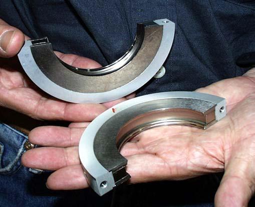
14 Final Machined PPM Elements C-band R&D Machining accuracy and surface roughness of all the PPM elements are within ±25-µm and ±0.6-µm respectively. COPPE R (OFC) Mag-SUS COPPE R (OFC) Vacuum capsule


15 C-band R&D Diffusion Bonding of PPM Stack Copper pipe PPM Stack HOT ISOSTATIC PRESSING 2 Hours Heater Ar GAS 1200 kgf / cm Time
: 800 C, 1200 kgf/cm 2 and 2")
 Cutaway view of")
16 C-band R&D Machineability Survey on PPM Stack Diffusion bonded sample Hot Isostatic Pressing (HIP): 800 C, 1200 kgf/cm 2 and 2 hours Tensile strength: 213 ~ 216 N/mm 2 No He-leak at Atm cm 3 /s (after heat cycle at 900 C and 10 minute) Cutaway view of PPM stack


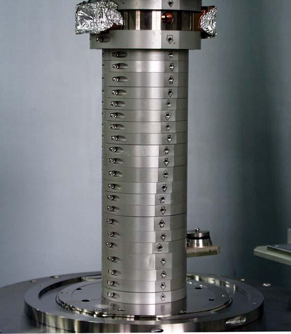
17 PPM Stacks after Final Machining Diffusion bonded PPM stuck used HIP method at 1200 kgf/cm 2 of Ar-gas pressure, 800 deg-c of temperature for 2 hours. C-band R&D Magnetic stainless steel Input cavity Input cavity Tensile strength at bonded zone is 213~216 N/mm 2. End beam pipe All PPM stacks displayed from input cavity (up left) to end beam pipe (down right).

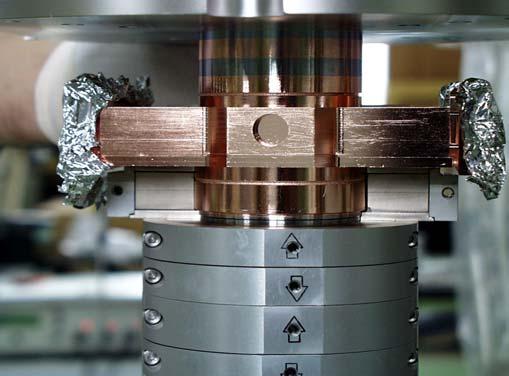
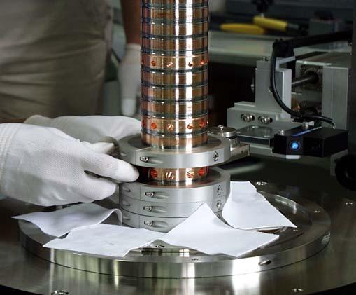
18 C-band R&D PPM-module Mounting Procedure


19 C-band R&D The 1 st C-band PPM Klystron is Under Testing Target performances are RF output power: 50 MW Voltage: 350 kv Repetition rate: 50 pps


20 RF Pulse Compressor C-band R&D Cold-Model Cavity φ 153 TE0,1,15 TE0,1,5 TE0,1, m Mode Converter


21 Test Result on Cold Model C-band R&D 1997 Compressed Pulse Magnified View G v 3.3 Flat top 230 nsec 0.5 µs/div * 5712 MHz, Low level signal, * AM-modulation by a mixer, * HP function generator 0.1 µs/div

22 C-band R&D TE 01,15 test cavity for Pulse Compressor Q 0 = (97%), Q ext = EBW brazing OFC Super invar with copper electroforming OFC MOF Mode converter TE 10 TE 01


23 C-band Smart Modulator No. 1 C-band R&D Charging voltage of EMI-303 Inverter power supply EMI-303 Peak power output: 111 MW Average power output: 39 kw Charging voltage: 47 kv Flat top pulse width: 2.5 µsec Thyratron switch noise ~5 MHz 23 kv, 4600 A PFN output voltage
24 C-BAND 50 MW KLYSTRON C-band Closed type Compact Modulator for FEL project W: 1600, D: 1500, H: 1000 Include two set of modules (1766) (1966)
25 SPring-8 Compact SASE Source (SCSS) presented by T. Shintake Project Overview Milestone Key Technology Electron Gun High-gradient C-band Accelerator In-vacuum Undulator

26 Where to build FEL? Experimental Hall S ring-8
27 What is SASE? Self Amplification of Spontaneous Emission (Noise) No Mirror is available below 100 nm. No seeding source is available. Noise Noise Noise Noise output Coherency is quite limited (~1µm) Monocromatic (~0.1%width)
28 SPring-8 Compact SASE Source E = 0.5 MeV Ipk = 3 A t = 0.33 nsec q = 1 nc 20 MeV 30 A 33 psec 1 nc z~10 mm 20 MeV 250 A 4 psec 1 nc 1.2 mm E = 300 MeV Ipk = 2 ka t = 0.5 psec.fwhm q = 1 nc z = 0.15 mm.fwhm E = 1 GeV Ipk = 2 ka t = 0.5 psec.fwhm q = 1 nc z = 0.15 mm.fwhm σe/e = 2x10 4 εn = 2 πmm.mrad λ x = 3.6 nm ρ =8.9 x 10 4 Lg = 0.94 m Lsat = 20 m Psat = 1.9 GW 500 kv Pulse Gun 476 MHz Buncher ~200 kv L-band Linac C-band Linac C-band Linac Undulator BC1 Unit-1 BC2 Unit-2 Unit-3 Unit-4 Energy Filter 20 MV 1 m 476 MHz Stepup Cavity ~600 kv x1/ MV/m 1.8 m x 4/unit 288 MeV/unit C-band Correction Cavity ~1 MV x1/8 40 MV/m 1.8 m x 4/unit 288 MeV/unit λu = 15 mm Kmax = 1.3 g.min = 3.7 mm <βx,y> = 10 m L = 4.5 x 5 = 22.5 m
29
30 HV Pulse Gun Sub-harmonic Buncher Energy Filter 476MHz Step-up Accelerator L-Band Accelerator Bunch Compressor BC EZ : Einzel Lens HS, VS : Steering Screen Monitor Troid Current Monitor Collimator Beam Chopper (pulse shaping) 476 MHz, 200 kv Vertical Slit (beam chopper) Horizontal Slit (energy gate) 476 MHz, 700 kv 1428 MHz 10 Cell, 1 m APS Standing Wave Energy Gain 20 MV S-band Correction Cavity To Main Linac 1:20 Cathode CeB6 single-crystal φ3 mm 1450 deg.c εn 0.4 π µrad Vp 500 kv I p 3 A t FWHM 300 nsec fr 60 pps K 0.01 µa/v 1.5 Filter 400~600 kv I p 3 A t FWHM 0.3 nsec Vp 1 MV I p 10 A t FWHM 100 psec Q 1 nc Vp 20 MV I p 30 A t FWHM 33 psec Q 1 nc Vp 20 MV I p 250 A t FWHM 4 psec Q 1 nc
Current status of XFEL/SPring-8 project and SCSS test accelerator
 Current status of XFEL/SPring-8 project and SCSS test accelerator Takahiro Inagaki for XFEL project in SPring-8 inagaki@spring8.or.jp Outline (1) Introduction (2) Key technology for compactness (3) Key
Detailed Design Report
 Detailed Design Report Chapter 4 MAX IV Injector 4.6. Acceleration MAX IV Facility CHAPTER 4.6. ACCELERATION 1(10) 4.6. Acceleration 4.6. Acceleration...2 4.6.1. RF Units... 2 4.6.2. Accelerator Units...
4.4 Injector Linear Accelerator
 4.4 Injector Linear Accelerator 100 MeV S-band linear accelerator based on the components already built for the S-Band Linear Collider Test Facility at DESY [1, 2] will be used as an injector for the CANDLE
INFN School on Electron Accelerators. RF Power Sources and Distribution
 INFN School on Electron Accelerators 12-14 September 2007, INFN Sezione di Pisa Lecture 7b RF Power Sources and Distribution Carlo Pagani University of Milano INFN Milano-LASA & GDE The ILC Double Tunnel
KEKB INJECTOR LINAC AND UPGRADE FOR SUPERKEKB
 KEKB INJECTOR LINAC AND UPGRADE FOR SUPERKEKB S. Michizono for the KEK electron/positron Injector Linac and the Linac Commissioning Group KEK KEKB injector linac Brief history of the KEK electron linac
THE NEXT LINEAR COLLIDER TEST ACCELERATOR: STATUS AND RESULTS * Abstract
 SLAC PUB 7246 June 996 THE NEXT LINEAR COLLIDER TEST ACCELERATOR: STATUS AND RESULTS * Ronald D. Ruth, SLAC, Stanford, CA, USA Abstract At SLAC, we are pursuing the design of a Next Linear Collider (NLC)
RF considerations for SwissFEL
 RF considerations for H. Fitze in behalf of the PSI RF group Workshop on Compact X-Ray Free Electron Lasers 19.-21. July 2010, Shanghai Agenda Introduction RF-Gun Development C-band development Summary
Evaluation of Performance, Reliability, and Risk for High Peak Power RF Sources from S-band through X-band for Advanced Accelerator Applications
 Evaluation of Performance, Reliability, and Risk for High Peak Power RF Sources from S-band through X-band for Advanced Accelerator Applications Michael V. Fazio C. Adolphsen, A. Jensen, C. Pearson, D.
Experience with the Cornell ERL Injector SRF Cryomodule during High Beam Current Operation
 Experience with the Cornell ERL Injector SRF Cryomodule during High Beam Current Operation Matthias Liepe Assistant Professor of Physics Cornell University Experience with the Cornell ERL Injector SRF
Overview of NLC/JLC Collaboration *
 SLAC PUB 10117 August 2002 Overview of NLC/JLC Collaboration * K. Takata KEK, Oho, Tsukuba-shi 305-0801, JAPAN On behalf of the NLC Group Stanford Linear Accelerator Center, Stanford, California 94309,
Photo cathode RF gun -
 Photo cathode RF gun - *),,, ( 05 Nov. 2004 Spring8 UTNL Linac & Mg Photocathode RF Gun Mg photocathode NERL, 18 MeV Linac and the RF gun Electron Beam Mg photocathode Mg photocathode RF gun of SPring8
DEVELOPMENT OF X-BAND KLYSTRON TECHNOLOGY AT SLAC
 DEVELOPMENT OF X-BAND KLYSTRON TECHNOLOGY AT SLAC George Caryotakis, Stanford Linear Accelerator Center P.O. Box 4349 Stanford, CA 94309 Abstract * The SLAC design for a 1-TeV collider (NLC) requires klystrons
Present Status and Future Upgrade of KEKB Injector Linac
 Present Status and Future Upgrade of KEKB Injector Linac Kazuro Furukawa, for e /e + Linac Group Present Status Upgrade in the Near Future R&D towards SuperKEKB 1 Machine Features Present Status and Future
DESIGN AND PERFORMANCE OF L-BAND AND S-BAND MULTI BEAM KLYSTRONS
 DESIGN AND PERFORMANCE OF L-BAND AND S-BAND MULTI BEAM KLYSTRONS Y. H. Chin, KEK, Tsukuba, Japan. Abstract Recently, there has been a rising international interest in multi-beam klystrons (MBK) in the
LCLS RF Reference and Control R. Akre Last Update Sector 0 RF and Timing Systems
 LCLS RF Reference and Control R. Akre Last Update 5-19-04 Sector 0 RF and Timing Systems The reference system for the RF and timing starts at the 476MHz Master Oscillator, figure 1. Figure 1. Front end
NEW METHOD FOR KLYSTRON MODELING
 NEW METHOD FOR KLYSTRON MODELING Y. H. Chin, KEK, 1-1 Oho, Tsukuba-shi, Ibaraki-ken, 35, Japan Abstract We have developed a new method for a realistic and more accurate simulation of klystron using the
PULSED MODULATOR TECHNOLOGY
 PULSED MODULATOR TECHNOLOGY Hiroshi MATSUMOTO J-PARC/KEK CONTENTS 1. VARIOUS REQUIREMENT OF THE RECENT MODULATORS SHORT PULSE WIDTH (~µsec) LONG PULSE WIDTH (~msec) AND HIGH REP. RATE. (200 Hz) OUTPUT
STATUS OF THE SWISSFEL C-BAND LINEAR ACCELERATOR
 Proceedings of FEL213, New York, NY, USA STATUS OF THE SWISSFEL C-BAND LINEAR ACCELERATOR F. Loehl, J. Alex, H. Blumer, M. Bopp, H. Braun, A. Citterio, U. Ellenberger, H. Fitze, H. Joehri, T. Kleeb, L.
Linac upgrade plan using a C-band system for SuperKEKB
 Linac upgrade plan using a C-band system for SuperKEKB S. Fukuda, M. Akemono, M. Ikeda, T. Oogoe, T. Ohsawa, Y. Ogawa, K. Kakihara, H. Katagiri, T. Kamitani, M. Sato, T. Shidara, A. Shirakawa, T. Sugimura,
The Elettra Storage Ring and Top-Up Operation
 The Elettra Storage Ring and Top-Up Operation Emanuel Karantzoulis Past and Present Configurations 1994-2007 From 2008 5000 hours /year to the users 2010: Operations transition year Decay mode, 2 GeV (340mA)
Activities on FEL Development and Application at Kyoto University
 Activities on FEL Development and Application at Kyoto University China-Korea-Japan Joint Workshop on Electron / Photon Sources and Applications Dec. 2-3, 2010 @ SINAP, Shanghai Kai Masuda Inst. Advanced
J/NLC Progress on R1 and R2 Issues. Chris Adolphsen
 J/NLC Progress on R1 and R2 Issues Chris Adolphsen Charge to the International Linear Collider Technical Review Committee (ILC-TRC) To assess the present technical status of the four LC designs at hand,
Design Studies For The LCLS 120 Hz RF Gun Injector
 BNL-67922 Informal Report LCLS-TN-01-3 Design Studies For The LCLS 120 Hz RF Gun Injector X.J. Wang, M. Babzien, I. Ben-Zvi, X.Y. Chang, S. Pjerov, and M. Woodle National Synchrotron Light Source Brookhaven
Towards an X-Band Power Source at CERN and a European Structure Test Facility
 Towards an X-Band Power Source at CERN and a European Structure Test Facility Erk Jensen and Gerry McMomagle CERN The X-Band Accelerating Structure Design and Test-Program Workshop Day 2: Structure Testing
PEP II Design Outline
 PEP II Design Outline Balša Terzić Jefferson Lab Collider Review Retreat, February 24, 2010 Outline General Information Parameter list (and evolution), initial design, upgrades Collider Ring Layout, insertions,
Spear3 RF System Sam Park 11/06/2003. Spear3 RF System. High Power Components Operation and Control. RF Requirement.
 Spear3 RF System RF Requirement Overall System High Power Components Operation and Control SPEAR 3 History 1996 Low emittance lattices explored 1996 SPEAR 3 proposed 11/97 SPEAR 3 design study team formed
45 MW, 22.8 GHz Second-Harmonic Multiplier for High-Gradient Tests*
 US High Gradient Research Collaboration Workshop. SLAC, May 23-25, 2007 45 MW, 22.8 GHz Second-Harmonic Multiplier for High-Gradient Tests* V.P. Yakovlev 1, S.Yu. Kazakov 1,2, and J.L. Hirshfield 1,3 1
Status of RF Power and Acceleration of the MAX IV - LINAC
 Status of RF Power and Acceleration of the MAX IV - LINAC Dionis Kumbaro ESLS RF Workshop 2015 MAX IV Laboratory A National Laboratory for synchrotron radiation at Lunds University 1981 MAX-lab is formed
CLIC Feasibility Demonstration at CTF3
 CLIC Feasibility Demonstration at CTF3 Roger Ruber Uppsala University, Sweden, for the CLIC/CTF3 Collaboration http://cern.ch/clic-study LINAC 10 MO303 13 Sep 2010 The Key to CLIC Efficiency NC Linac for
A HIGH POWER LONG PULSE HIGH EFFICIENCY MULTI BEAM KLYSTRON
 A HIGH POWER LONG PULSE HIGH EFFICIENCY MULTI BEAM KLYSTRON A.Beunas and G. Faillon Thales Electron Devices, Vélizy, France S. Choroba DESY, Hamburg, Germany Abstract THALES ELECTRON DEVICES has developed
3 cerl. 3-1 cerl Overview. 3-2 High-brightness DC Photocathode Gun and Gun Test Beamline
 3 cerl 3-1 cerl Overview As described before, the aim of the cerl in the R&D program includes the development of critical components for the ERL, as well as the construction of a test accelerator. The
Status of the X-ray FEL control system at SPring-8
 Status of the X-ray FEL control system at SPring-8 T.Fukui 1, T.Hirono 2, N.Hosoda 1, M.Ishii 2, M.Kitamura 1 H.Maesaka 1,T.Masuda 2, T.Matsushita 2, T.Ohata 2, Y.Otake 1, K.Shirasawa 1,M.Takeuchi 2, R.Tanaka
Pulsed Klystrons for Next Generation Neutron Sources Edward L. Eisen - CPI, Inc. Palo Alto, CA, USA
 Pulsed Klystrons for Next Generation Neutron Sources Edward L. Eisen - CPI, Inc. Palo Alto, CA, USA Abstract The U.S. Department of Energy (DOE) Office of Science has funded the construction of a new accelerator-based
Performance of a DC GaAs photocathode gun for the Jefferson lab FEL
 Nuclear Instruments and Methods in Physics Research A 475 (2001) 549 553 Performance of a DC GaAs photocathode gun for the Jefferson lab FEL T. Siggins a, *, C. Sinclair a, C. Bohn b, D. Bullard a, D.
TITLE PAGE. Title of paper: PUSH-PULL FEL, A NEW ERL CONCEPT Author: Andrew Hutton. Author Affiliation: Jefferson Lab. Requested Proceedings:
 TITLE PAGE Title of paper: PUSH-PULL FEL, A NEW ERL CONCEPT Author: Andrew Hutton Author Affiliation: Jefferson Lab Requested Proceedings: Unique Session ID: Classification Codes: Keywords: Energy Recovery,
Diamond RF Status (RF Activities at Daresbury) Mike Dykes
 Mike Dykes") Diamond RF Status (RF Activities at Daresbury) Mike Dykes ASTeC What is it? What does it do? Diamond Status Linac Booster RF Storage Ring RF Summary Content ASTeC ASTeC was formed in 2001 as a centre of
Diamond RF Status (RF Activities at Daresbury) Mike Dykes ASTeC What is it? What does it do? Diamond Status Linac Booster RF Storage Ring RF Summary Content ASTeC ASTeC was formed in 2001 as a centre of
DELIVERY RECORD. Location: Ibaraki, Japan
 DELIVERY RECORD Client: Japan Atomic Energy Agency (JAEA) High Energy Accelerator Research Organization (KEK) Facility: J-PARC (Japan Proton Accelerator Research Complex) Location: Ibaraki, Japan 1 October
DEVELOPMENT OF A 10 MW SHEET BEAM KLYSTRON FOR THE ILC*
 DEVELOPMENT OF A 10 MW SHEET BEAM KLYSTRON FOR THE ILC* D. Sprehn, E. Jongewaard, A. Haase, A. Jensen, D. Martin, SLAC National Accelerator Laboratory, Menlo Park, CA 94020, U.S.A. A. Burke, SAIC, San
PRESENT STATUS OF J-PARC
 PRESENT STATUS OF J-PARC # F. Naito, KEK, Tsukuba, Japan Abstract Japan Proton Accelerator Research Complex (J-PARC) is the scientific facility with the high-intensity proton accelerator aiming to realize
XFEL High Power RF System Recent Developments
 XFEL High Power RF System Recent Developments for the XFEL RF Group Outline XFEL RF System Requirements Overview Basic Layout RF System Main Components Multibeam Klystrons Modulator RF Waveguide Distribution
!"!3
 Abstract A single-mode 500 MHz superconducting cavity cryomodule has been developed at Cornell for the electronpositron collider/synchrotron light source CESR. The Cornell B-cell cavity belongs to the
Jae-Young Choi On behalf of PLS-II Linac team
 PLS-II Linac 2015. 4. 8. Jae-Young Choi On behalf of PLS-II Linac team Accelerators in Pohang Accelerator Laboratory XFEL (under construction) 400 M$ Machines under installation PLS-II PAL : Chronology
NSLS-II RF Systems James Rose, Radio Frequency Group Leader PAC 2011
 NSLS-II RF Systems James Rose, Radio Frequency Group Leader PAC 2011 1 BROOKHAVEN SCIENCE ASSOCIATES Introduction Linac RF cavities and klystrons Booster Cavity-Transmitter Storage Ring 500 MHz SRF cavity
L-Band RF R&D. SLAC DOE Review June 15 th, Chris Adolphsen SLAC
 L-Band RF R&D SLAC DOE Review June 15 th, 2005 Chris Adolphsen SLAC International Linear Collider (ILC) RF Unit (TESLA TDR Layout) Gradient = 23.4 MV/m Bunch Spacing = 337 ns Fill Time = 420 µs Train Length
SUMMARY OF THE ILC R&D AND DESIGN
 SUMMARY OF THE ILC R&D AND DESIGN B. C. Barish, California Institute of Technology, USA Abstract The International Linear Collider (ILC) is a linear electron-positron collider based on 1.3 GHz superconducting
IOT OPERATIONAL EXPERIENCE ON ALICE AND EMMA AT DARESBURY LABORATORY
 IOT OPERATIONAL EXPERIENCE ON ALICE AND EMMA AT DARESBURY LABORATORY A. Wheelhouse ASTeC, STFC Daresbury Laboratory ESLS XVIII Workshop, ELLETRA 25 th 26 th November 2010 Contents Brief Description ALICE
Next Linear Collider. The 8-Pack Project. 8-Pack Project. Four 50 MW XL4 X-band klystrons installed on the 8-Pack
 The Four 50 MW XL4 X-band klystrons installed on the 8-Pack The Demonstrate an NLC power source Two Phases: 8-Pack Phase-1 (current): Multi-moded SLED II power compression Produce NLC baseline power: 475
Status of CTF3. G.Geschonke CERN, AB
 Status of CTF3 G.Geschonke CERN, AB CTF3 layout CTF3 - Test of Drive Beam Generation, Acceleration & RF Multiplication by a factor 10 Drive Beam Injector ~ 50 m 3.5 A - 2100 b of 2.33 nc 150 MeV - 1.4
STATUS REPORT ON THE COMMISSIONING OF THE JAPANESE XFEL AT SPRING-8
 STATUS REPORT ON THE COMMISSIONING OF THE JAPANESE XFEL AT SPRING-8 H. Tanaka #, RIKEN/SPring-8, 1-1-1, Kouto, Sayo-cho, Sayo-gun, Hyogo 679-5148, Japan. Abstract The X-ray free electron laser (XFEL) facility,
Tutorial: Trak design of an electron injector for a coupled-cavity linear accelerator
 Tutorial: Trak design of an electron injector for a coupled-cavity linear accelerator Stanley Humphries, Copyright 2012 Field Precision PO Box 13595, Albuquerque, NM 87192 U.S.A. Telephone: +1-505-220-3975
NLC - The Next Linear Collider Project NLC R&D. D. L. Burke. DOE Annual Program Review SLAC April 9-11, 2003
 DOE Annual Program Review SLAC April 9-11, 2003 NLC Activities for the Past Year Accelerator Design centered around ILC-TRC studies. Technology R&D focused on the RF R&D. Modulator, klystron, SLED-II,
High Brightness Injector Development and ERL Planning at Cornell. Charlie Sinclair Cornell University Laboratory for Elementary-Particle Physics
 High Brightness Injector Development and ERL Planning at Cornell Charlie Sinclair Cornell University Laboratory for Elementary-Particle Physics June 22, 2006 JLab CASA Seminar 2 Background During 2000-2001,
RF Power Generation II
 RF Power Generation II Klystrons, Magnetrons and Gyrotrons Professor R.G. Carter Engineering Department, Lancaster University, U.K. and The Cockcroft Institute of Accelerator Science and Technology Scope
Demonstra*on of Two- color XFEL Opera*on and Autocorrela*on Measurement at SACLA
 Demonstra*on of Two- color XFEL Opera*on and Autocorrela*on Measurement at SACLA Toru Hara, Yuichi Inubushi, Tetsuya Ishikawa, Takahiro Sato, Hitoshi Tanaka, Takashi Tanaka, Kazuaki Togawa, Makina Yabashi
PULSED POWER FOR FUTURE LINEAR ACCELERATORS
 PULSED POWER FOR FUTURE LINEAR ACCELERATORS Peter D. Pearce High-energy accelerators High-energy accelerators enable us to collide particle beams together and create conditions believed to be similar to
KARA and FLUTE RF Overview/status
 KARA and FLUTE RF Overview/status Nigel Smale on behalf of IBPT and LAS teams Laboratory for Applications of Synchrotron radiation (LAS) Institute for Beam Physics and Technology (IBPT) KARA KIT The Research
Overview of the X-band R&D Program
 Overview of the X-band R&D Program SLAC-PUB-9442 August 2002 Abstract T.O. Raubenheimer Stanford Linear Accelerator Center, Stanford University, Stanford, California 94309 USA An electron/positron linear
Oak Ridge Spallation Neutron Source Proton Power Upgrade Project and Second Target Station Project
 Oak Ridge Spallation Neutron Source Proton Power Upgrade Project and Second Target Station Project Workshop on the future and next generation capabilities of accelerator driven neutron and muon sources
X-Band Klystron Development at
 X-Band Klystron Development at SLAC Slide 1 The Beginning X-band klystron work began at SLAC in the mid to late 80 s to develop high frequency (4x SLAC s-band), high power RF sources for the linear collider
The Construction Status of CSNS Linac
 The Construction Status of CSNS Linac Sheng Wang Dongguan branch, Institute of High Energy Physics, CAS Sep.2, 2014, Geneva Outline The introduction to CSNS accelerators The commissoning of ion source
High-gradient C-band linac for a compact x-ray free-electron laser facility
 PHYSICAL REVIEW SPECIAL TOPICS - ACCELERATORS AND BEAMS 17, 080702 (2014) High-gradient C-band linac for a compact x-ray free-electron laser facility T. Inagaki, * C. Kondo, H. Maesaka, T. Ohshima, Y.
Cathode Studies at FLASH: CW and Pulsed QE measurements
 Cathode Studies at FLASH: CW and Pulsed QE measurements L. Monaco, D. Sertore, P. Michelato S. Lederer, S. Schreiber Work supported by the European Community (contract number RII3-CT-2004-506008) 1/27
30 GHz Power Production / Beam Line
 30 GHz Power Production / Beam Line Motivation & Requirements Layout Power mode operation vs. nominal parameters Beam optics Achieved performance Problems Beam phase switch for 30 GHz pulse compression
KLYSTRON GUN ARCING AND MODULATOR PROTECTION
 SLAC-PUB-10435 KLYSTRON GUN ARCING AND MODULATOR PROTECTION S.L. Gold Stanford Linear Accelerator Center (SLAC), Menlo Park, CA USA Abstract The demand for 500 kv and 265 amperes peak to power an X-Band
P. Emma, et al. LCLS Operations Lectures
 P. Emma, et al. LCLS Operations Lectures LCLS 1 LCLS Accelerator Schematic 6 MeV 135 MeV 250 MeV σ z 0.83 mm σ z 0.83 mm σ z 0.19 mm σ δ 0.05 % σ δ 0.10 % σ δ 1.6 % Linac-0 L =6 m rf gun L0-a,b Linac-1
STATUS OF THE SwissFEL C-BAND LINAC
 STATUS OF THE SwissFEL C-BAND LINAC F. Loehl, J. Alex, H. Blumer, M. Bopp, H. Braun, A. Citterio, U. Ellenberger, H. Fitze, H. Joehri, T. Kleeb, L. Paly, J.-Y. Raguin, L. Schulz, R. Zennaro, C. Zumbach,
The FLASH objective: SASE between 60 and 13 nm
 Injector beam control studies winter 2006/07 talk from E. Vogel on work performed by W. Cichalewski, C. Gerth, W. Jalmuzna,W. Koprek, F. Löhl, D. Noelle, P. Pucyk, H. Schlarb, T. Traber, E. Vogel, FLASH
Summary of recent photocathode studies
 Summary of recent photocathode studies S. Lederer, S. Schreiber DESY L. Monaco, D. Sertore INFN Milano LASA FLASH seminar November 17 th, 2009 Outlook Cs 2 Te photocathodes Pulsed QE measurements laser
The PEFP 20-MeV Proton Linear Accelerator
 Journal of the Korean Physical Society, Vol. 52, No. 3, March 2008, pp. 721726 Review Articles The PEFP 20-MeV Proton Linear Accelerator Y. S. Cho, H. J. Kwon, J. H. Jang, H. S. Kim, K. T. Seol, D. I.
Future Performance of the LCLS
 Future Performance of the LCLS J. Welch for many* SLAC National Accelerator Laboratory FLS 2010, ICFA Beam Dynamics Workshop on Future Light Sources, March 1-5, 2010. SLAC National Accelerator Laboratory,
Dark current and multipacting trajectories simulations for the RF Photo Gun at PITZ
 Dark current and multipacting trajectories simulations for the RF Photo Gun at PITZ Introduction The PITZ RF Photo Gun Field simulations Dark current simulations Multipacting simulations Summary Igor Isaev
TWO BUNCHES WITH NS-SEPARATION WITH LCLS*
 TWO BUNCHES WITH NS-SEPARATION WITH LCLS* F.-J. Decker, S. Gilevich, Z. Huang, H. Loos, A. Marinelli, C.A. Stan, J.L. Turner, Z. van Hoover, S. Vetter, SLAC, Menlo Park, CA 94025, USA Abstract The Linac
Accelerator Instrumentation RD. Monday, July 14, 2003 Marc Ross
 Monday, Marc Ross Linear Collider RD Most RD funds address the most serious cost driver energy The most serious impact of the late technology choice is the failure to adequately address luminosity RD issues
Digital BPMs and Orbit Feedback Systems
 Digital BPMs and Orbit Feedback Systems, M. Böge, M. Dehler, B. Keil, P. Pollet, V. Schlott Outline stability requirements at SLS storage ring digital beam position monitors (DBPM) SLS global fast orbit
TECHNICAL SPECIFICATION Multi-beam S-band Klystron type BT267
 TECHNICAL SPECIFICATION Multi-beam S-band Klystron type BT267 The company was created for the development and manufacture of precision microwave vacuum-electron-tube devices (VETD). The main product areas
Chapter 4. Rf System Design. 4.1 Introduction Historical Perspective NLC Rf System Overview
 Chapter 4 Rf System Design 4.1 Introduction 4.1.1 Historical Perspective The design of the NLC main linacs is based on the extensive experience gained from the design, construction, and 35 years of operation
RF plans for ESS. Morten Jensen. ESLS-RF 2013 Berlin
 RF plans for ESS Morten Jensen ESLS-RF 2013 Berlin Overview The European Spallation Source (ESS) will house the most powerful proton linac ever built. The average beam power will be 5 MW which is five
RF Upgrades & Experience At JLab. Rick Nelson
 RF Upgrades & Experience At JLab Rick Nelson Outline Background: CEBAF / Jefferson Lab History, upgrade requirements & decisions Progress & problems along the way Present status Future directions & concerns
Status and Plans for PEP-II
 Status and Plans for PEP-II John Seeman SLAC Particle and Particle-Astrophysics DOE HEPAP P5 Review April 21, 2006 Topics Luminosity records for PEP-II in October 2005 Fall shut-down upgrades Run 5b turn
Status of KEK X-band Test Facility and its future plans
 Status of KEK X-band Test Facility and its future plans Shuji Matsumoto Accelerator Lab., KEK 5/30/2007 US High Field Gradient Collaboration Workshop, SLAC. 1 Contents The New X-band Test Facility (XTF)
RUNNING EXPERIENCE OF FZD SRF PHOTOINJECTOR
 RUNNING EXPERIENCE OF FZD SRF PHOTOINJECTOR Rong Xiang On behalf of the BESSY-DESY-FZD-MBI collaboration and the ELBE team FEL 2009, Liverpool, United Kingdom, August 23 ~ 28, 2009 Outline Introduction
Nick Walker DESY MAC
 Nick Walker DESY MAC 4.5.2006 XFEL X-Ray Free-Electron Laser DESY ILC Project Group Accelerator Experimentation Behnke, Elsen, Walker (chair) WP 15, 16 WP 4-7 Accelerator Physics and Design WP 6 High Gradient
Summary of the 1 st Beam Line Review Meeting Injector ( )
") Summary of the 1 st Beam Line Review Meeting Injector (23.10.2006) 15.11.2006 Review the status of: beam dynamics understanding and simulations completeness of beam line description conceptual design of
Summary of the 1 st Beam Line Review Meeting Injector (23.10.2006) 15.11.2006 Review the status of: beam dynamics understanding and simulations completeness of beam line description conceptual design of
Status of SOLARIS Arkadiusz Kisiel
 Status of SOLARIS Arkadiusz Kisiel Solaris National Synchrotron Light Source Jagiellonian University Czerwone Maki 98 30-392 Kraków www.synchrotron.uj.edu.pl Arkadiusz.Kisiel@uj.edu.pl On behalf of SOLARIS
Status of BESSY II and berlinpro. Wolfgang Anders. Helmholtz-Zentrum Berlin for Materials and Energy (HZB) 20th ESLS-RF Meeting
 20th ESLS-RF Meeting") Status of BESSY II and berlinpro Wolfgang Anders Helmholtz-Zentrum Berlin for Materials and Energy (HZB) 20th ESLS-RF Meeting 16.-17.11.2016 at PSI Outline BESSY II Problems with circulators Landau cavity
Status of BESSY II and berlinpro Wolfgang Anders Helmholtz-Zentrum Berlin for Materials and Energy (HZB) 20th ESLS-RF Meeting 16.-17.11.2016 at PSI Outline BESSY II Problems with circulators Landau cavity
FIRST SIMULTANEOUS TOP-UP OPERATION OF THREE DIFFERENT RINGS IN KEK INJECTOR LINAC
 FIRST SIMULTANEOUS TOP-UP OPERATION OF THREE DIFFERENT RINGS IN KEK INJECTOR LINAC M. Satoh #, for the IUC * Accelerator Laboratory, High Energy Accelerator Research Organization (KEK) 1-1 Oho, Tsukuba,
Low-Energy Electron Linacs and Their Applications in Cargo Inspection
 Low-Energy Electron Linacs and Their Applications in Cargo Inspection Yawei Yang on behalf of Huaibi Chen *,1, Chuanxiang Tang 1 Yaohong Liu 2 *chenhb@tsinghua.edu.cn 1 Department of Engineering Physics,
STATUS OF THE INTERNATIONAL LINEAR COLLIDER
 STATUS OF THE INTERNATIONAL LINEAR COLLIDER K. Yokoya, KEK, Tsukuba, Japan Abstract The International Linear Collider (ILC) is the nextgeneration electron-positron collider. Since the publication of the
A Facility for Accelerator Physics and Test Beam Experiments
 A Facility for Accelerator Physics and Test Beam Experiments U.S. Department of Energy Review Roger Erickson for the FACET Design Team February 20, 2008 SLAC Overview with FACET FACET consists of four
First Simultaneous Top-up Operation of Three Different Rings in KEK Injector Linac
 First Simultaneous Top-up Operation of Three Different Rings in KEK Injector Linac Masanori Satoh (Acc. Lab., KEK) for the injector upgrade group 2010/9/16 1 Overview of Linac Beam Operation 2010/9/16
RECENT PROGRESS IN UPGRADE OF THE HIGH INTENSITY THzzz zz-fel AT OzSAKzA UNIVERSITYzzzz
 RECENT PROGRESS IN UPGRADE OF THE HIGH INTENSITY THzzz zz-fel AT OzSAKzA UNIVERSITYzzzz G. Isoyama#, M. Fujimoto, S. Funakoshi, K. Furukawa, A. Irizawa, R. Kato, K. Kawase, A. Tokuchi, R. Tsutsumi, M.
STATUS AND FUTURE PROSPECTS OF CLIC
 STATUS AND FUTURE PROSPECTS OF CLIC S. Döbert, for the CLIC/CTF3 collaboration, CERN, Geneva, Switzerland Abstract The Compact Linear Collider (CLIC) is studied by a growing international collaboration.
Screen investigations for low energetic electron beams at PITZ
 1 Screen investigations for low energetic electron beams at PITZ S. Rimjaem, J. Bähr, H.J. Grabosch, M. Groß Contents Review of PITZ setup Screens and beam profile monitors at PITZ Test results Summary
Jefferson Lab Experience with Beam Halo, Beam Loss, etc.
 Jefferson Lab Experience with Beam Halo, Beam Loss, etc. Pavel Evtushenko with a lot of input from many experienced colleagues Steve Benson, Dave Douglas, Kevin Jordan, Carlos Hernandez-Garcia, Dan Sexton,
Pulses inside the pulse mode of operation at RF Gun
 Pulses inside the pulse mode of operation at RF Gun V. Vogel, V. Ayvazyan, K. Floettmann, D. Lipka, P. Morozov, H. Schlarb, S. Schreiber FLASH Seminar, DESY March 29, 2011 Contents Why we need a PiPmode
Upgrading LHC Luminosity
 1 Upgrading LHC Luminosity 2 Luminosity (cm -2 s -1 ) Present (2011) ~2 x10 33 Beam intensity @ injection (*) Nominal (2015?) 1 x 10 34 1.1 x10 11 Upgraded (2021?) ~5 x10 34 ~2.4 x10 11 (*) protons per
WG2 Group Summary. Chris Adolphsen Terry Garvey Hitoshi Hayano
 WG2 Group Summary Chris Adolphsen Terry Garvey Hitoshi Hayano Linac Options Fest On Thursday afternoon, various experts summarized the linac baseline options. Although hard choices have yet to be made,
Design, Fabrication and Testing of Gun-Collector Test Module for 6 MW Peak, 24 kw Average Power, S-Band Klystron
 Available online www.ejaet.com European Journal of Advances in Engineering and Technology, 2014, 1(1): 11-15 Research Article ISSN: 2394-658X Design, Fabrication and Testing of Gun-Collector Test Module
ILC-LNF TECHNICAL NOTE
 IL-LNF EHNIAL NOE Divisione Acceleratori Frascati, July 4, 2006 Note: IL-LNF-001 RF SYSEM FOR HE IL DAMPING RINGS R. Boni, INFN-LNF, Frascati, Italy G. avallari, ERN, Geneva, Switzerland Introduction For
Commissioning of Accelerators. Dr. Marc Munoz (with the help of R. Miyamoto, C. Plostinar and M. Eshraqi)
") Commissioning of Accelerators Dr. Marc Munoz (with the help of R. Miyamoto, C. Plostinar and M. Eshraqi) www.europeanspallationsource.se 6 July, 2017 Contents General points Definition of Commissioning
Commissioning of Accelerators Dr. Marc Munoz (with the help of R. Miyamoto, C. Plostinar and M. Eshraqi) www.europeanspallationsource.se 6 July, 2017 Contents General points Definition of Commissioning