Distributed Antenna System TESTING GUIDE
|
|
|
- Sylvia Hardy
- 6 years ago
- Views:
Transcription

1 Distributed Antenna System TESTING GUIDE


2
3 Table of Contents 1. Wireline Challenges in the Wireless Space Small Cells RRH DAS DAS vs. RRH Fiber to the Cell Site Key Physical Parameters That Can Affect DAS Performance Loss Budget What Can Affect the Loss Budget? Bad Connection Macrobends and Their Effects DAS Testing Methods Construction Connector Maintenance Insertion Loss and Optical Return Loss Characterization Using a Traditional OTDR: Using the iolm: Alternative Methods Troubleshooting a Live System Tools That Can Be Used to Troubleshoot a System Troubleshooting Process Fiber Troubleshooting Test Documentation Distributed Antenna System EXFO 1
4 1. Wireline Challenges in the Wireless Space All across the globe, the landscape of high-rise buildings and municipal water towers is changing. These locations were once barren, but are now home to core macrocellular network installations, specifically cell towers and antennas. Using high-power radio frequency (RF) signals, macrocell sites allow wireless service providers (WSPs) to deliver voice, text and broadband communications over large geographic areas. Unfortunately, as traffic increases, coverage radius decreases. This means that even though cells can be upgraded, coverage cannot be expanded. Essentially, the best way to feed bandwidth to the entire wireless infrastructure is to increase fiber connectivity and penetration. With that in mind, this paper covers the function and role of antennas, fiber-optic infrastructure requirements, as well as best testing practices. The HetNet Reality In the stone age of cellular phones, back when voice communication was the only offering, network design focused on coverage, not capacity. Today s phones have morphed into portable, application-oriented, internet-enabled computers, greatly increasing the strain on network capacity. Unfortunately, adding new macro sites, microcells and picocells simply won t cut it. A better way to augment the macro layer is by adding low-power nodes like femtocells, remote radio heads/units (RRHs/RRUs) and distributed antenna systems (DAS). This enhanced macrocellular network is called a heterogeneous network, or HetNet. 2 EXFO Distributed Antenna System

5 1.1 Small Cells From humble beginnings, small cells are now flourishing. Femtocell: A small base station designed for residential use. Picocell: A base station that is larger than a femtocell, but smaller than a microcell. These stations can typically handle 10 to 60 simultaneous callers, but in some cases are capable of servicing over 100 callers. Picocells are deployed both indoors and outdoors. Microcell: A base station larger than a picocell, but with a smaller coverage area and capacity than a macrocell. These stations are often used to support cellular service in large buildings, conference centers and shopping malls. In high-rise buildings, they feed the DAS to extend coverage to multiple floors. Macrocell: > 256 users Femtocell: < 30 users Picocell: 30 to 100 users Microcell: > 100 users Distributed Antenna System EXFO 3
6 1.2 RRH A remote radio head is a single, outdoor unit with RF front-end functionalities only, and that connects to the baseband processing part of a distributed base station via a point-to-point, bidirectional, analog or digital interconnection link. However, other links are possible, namely star, ring and daisy chain. Analog links, due to their linearity requirements, require a highly linear system to maintain their spectral emission properties when transporting low-level RF composite signals. Although optical-fiber interconnection cables offer high linearity, they require very expensive optical lasers and drivers. 1.3 DAS Today, DAS is considered a multiple-airlink, multiple-frequency-band and multiple WSP system that is mostly fiber-opticsor coax-based. Designed to distribute cellular signals throughout buildings, active DAS equipment uses head-end and remote units to exploit the expensive part (i.e., the base station) as much as possible. Since a DAS enables the independent operation of multiple frequency bands and protocols across a single access network, multiple operator network sharing is supported. This capability is the secret to its success in the US market. 4 EXFO Distributed Antenna System
7 1.4 DAS vs. RRH DAS and RRH architectures are similar in a number of ways. They both centralize the baseband processing of the base station at one location, and use strategically located radio modules to satisfy coverage or capacity requirements. Both also use optical fiber to run very high data rates and high-capacity backhaul needs at baseband-unit locations. They both also excel in areas where ultra-high-density nodes are required. DAS can be considered as an evolution from RRH in the sense that DAS can transport data relevant to multiple RF carriers and multiple WSPs. However, this also means DAS demands a much higher overall link data rate. On the other hand, RRH can also be considered as an evolution from DAS. While DAS extends the coverage of legacy base stations, RRH offers cost-reducing base-station design. Another major difference is that unlike DAS, which uses RF-optical converters as add-on modules, RRH does not require converters, because it already uses optical technology. Distributed Antenna System EXFO 5
8 Low Data Rate (radio or optical link) RF Subsystem Provider #1 BASE STATION Provider #1 Tx Rx main Rx div. Local Interface Module Low Data Rate (radio or optical link) RF Subsystem Provider #1 BASE STATION Provider #1 BASE STATION Provider #2 Tx Rx main Rx div. Tx Rx main Rx div. Local Interface Module Local Interface Module High Data Rate (radio or optical link) RF Subsystem Provider #1 RF Subsystem Provider #1 RF Subsystem Provider #2 RF Subsystem Provider #2 High Data Rate (radio or optical link) Figure 1 DAS architecture for three colocated base stations from two different providers and six remotized RF subsystems 6 EXFO Distributed Antenna System
9 Low Data Rate (radio or optical link) RF Subsystem Provider #1 BASE STATION Provider #1 Tx Rx main Rx div. Low Data Rate (radio or optical link) RF Subsystem Provider #1 BASE STATION Provider #1 Tx Rx main Rx div. DAS RF Subsystem Provider #1 RF Subsystem Provider #1 BASE STATION Provider #2 Tx Rx main Rx div. RF Subsystem Provider #1 High Data Rate (optical link) RF Subsystem Provider #1 Figure 2 RRH architecture for three colocated base stations from two different providers and six remotized RF subsystems Distributed Antenna System EXFO 7
10 1.5 Fiber to the Cell Site By bringing high data rate to the radio/antenna, fiber-optic links deliver the promises made by mobile broadband. Increasing broadband capacity means growing the wireless network, which decreases the cell radius. Therefore, feeding bandwidth to the entire wireless infrastructure means increasing fiber connectivity and penetration. Essentially, more wireless means better and deeper wireline. Two standards are used to carry traffic over fiber from the base station s radio equipment controller (REC) to the radio equipment: common public radio interference (CPRI) and open base station architecture initiative (OBSAI). CPRI is the predominant standard. Wireless 4G Wireline Cellular Fiber, Ethernet, T1 (HDSL) FTTx Wi-Fi Figure 3 Out of the air and into the ground at the closest point 8 EXFO Distributed Antenna System
 transport medium that will")
11 3G/4G Data Capacity, 2.5G/3G Data Figure 4 Fiber-optic systems are the key physical (PHY) transport medium that will unify these new, distributed architectures Distributed Antenna System EXFO 9
12 Macrocell Base Station Fronthaul Radio Network/ Base Station Controller CWDM/DWDM Metro Ring In-Bulding DAS Fronthaul Backhaul Demarcation Cabinet Cell Site ILEC CLEC T1/Gigabit Ethernet Base Station Backhaul Demarcation Cabinet Operations Centre MTSO and Data Centre Base Station Figure 5 Fiber unifies the wireless NGN 10 EXFO Distributed Antenna System
13 The purpose of any fiber-optic network is to perform high-speed, error-free data transmission. The best testing practices are required at each phase to achieve the expected data rate and reliability while minimizing costly and time-consuming troubleshooting efforts, including locating dirty/damaged connectors, questionable splices and other faulty components. In the case of DAS, because a single system can transport data from multiple carriers, the fiber infrastructure has to be installed, qualified, tested and certified by a third party (e.g., antenna or network owner, subcontractor). Moreover, a birth certificate and proof of proper installation is often required. 2.0 Key Physical Parameters That Can Affect DAS Performance As previously stated, the purpose of any fiber-optic network is to perform high-speed, error-free data transmission. Adequate testing during each phase of the network deployment guarantees that products meet specifications, in addition to minimizing costly and time-consuming troubleshooting efforts, including locating dirty/damaged connectors, questionable splices and other faulty components before they disrupt service. One of the most important factors in ensuring proper transmission is controlling power loss in the network against the link loss-budget specifications from the network design recommendation. This is done by establishing a total end-to-end loss budget with sufficient margin while reducing back reflection to a minimum. This is particularly true for analog RF video signals from extremely narrowband lasers, because strong back reflections degrade the quality of the signal transmission. The following section will take a closer look into those parameters that can greatly affect the performance of the network. Distributed Antenna System EXFO 11
14 2.1 The Loss Budget One of the first tasks to perform when designing fiber-optic networks is to evaluate the acceptable loss budget in order to create a product that will meet application requirements. What causes loss in the fiber? The loss includes both intrinsic attenuation and extrinsic discontinuities in a fiber-optic cable, such as connectors and splices. Link loss is wavelength-dependent, measured in decibels per kilometer or db/km, and used in calculations for determining overall loss budget. To adequately characterize the loss budget, the following key parameters are generally considered: Transmitter: Launch power, temperature and aging Fiber connections: Connectors and splices Cable: Fiber loss and temperature effects Receiver: Detector sensitivity Others: Safety margin and repairs When one of the above-listed variables fails to meet specifications, the performance of the network could be greatly affected, or worse, the degradation could lead to network failure. 12 EXFO Distributed Antenna System
15 An example of the typical total loss-budget calculation is illustrated as follows: Connector 1 Connector 2 Connector 3 End A Section m Section m End B Figure 6 Typical DAS fiber installation Connector losses, typically around 0.2 db per connector pair. Fiber loss, which is equal to attenuation multiplied by distance. The maximum distance is limited by the loss budget at the worse-case attenuation wavelength (1310 nm with around 0.33 db/km attenuation). The maximum length in a DAS application will be a few kilometers in a large deployment. The loss-budget calculation should be one of the first verifications performed prior to any deployment, and it should be mandatory to verify that the class of system selected is compatible with the topology to be deployed. If, for example, a system is designed with the elements present in Figure 1, and the launch power of the transmitter at 1550 nm is 0 dbm and the detector sensitivity is at 10 dbm, the permitted loss budget of 10 db will compromise the system performance. However, tighter design tolerances can be set in order to prevent long-term evolution of the network. For example, the typical budget loss in DAS will be between 1.5 and 5 db. Distributed Antenna System EXFO 13
16 If we take the network topology shown in Figure 6, the total loss can be calculated as shown below: Typical Loss (db) Number/Length Total Loss (db) Connector (APC) Fiber sections (fiber type G.652C) 1310 nm 1550 nm 0.35/km 0.20/km 1.9 km Total loss budget 1310 nm 1550 nm Table 1 Loss-budget calculation sample Therefore, the total loss measured during network deployment should not exceed the total loss budget allowed by the system design, and should also have enough margin to compensate for any loss fluctuation that could occur during the lifecycle of the system. 14 EXFO Distributed Antenna System
 of each element into consideration should be sufficient to ensure that the loss budget will be respected once the elements are deployed.")
17 2.2 What Can Affect the Loss Budget? As we saw in the previous section, the optical distribution fiber is comprised of several elements that respectively contribute to the overall loss in a system. In theory, taking the theoretical insertion loss (e.g., fiber attenuation) of each element into consideration should be sufficient to ensure that the loss budget will be respected once the elements are deployed. Unfortunately, this is not the case, and the following sections will highlight a few phenomena that could eventually affect the insertion loss (IL) or optical return loss (ORL) of these elements when the time comes to deploy them in the field. As previously mentioned, the phenomena that will create exaggerated IL or ORL can be intrinsic or extrinsic to the fiber. The figure below illustrates a few examples of these elements. Distributed Antenna System EXFO 15

18 Figure 7 Phenomena affecting the overall loss budget Insertion loss is the increase in attenuation caused by inserting a connector pair (or passive component) into a fiber-optic link. A certain number of signals will be lost at each point. Optical return loss is the ratio of the forward optical power to the reflected optical power. When light is injected into a fiber-optic component, such as a connector, multiplexer or the fiber itself, some of the energy is transmitted, some is absorbed and some is reflected. The total light that comes back (i.e., is reflected) is what we refer to as ORL. ORL is caused by two fundamental effects. The first is the Rayleigh scattering effect, which is specifically the part that goes back to the source point, known as backscattering. The second effect consists of Fresnel reflections (Figure 8), which are small portions of light that are reflected back when light travels through materials of differing indexes of reflection. 16 EXFO Distributed Antenna System

19 Figure 8 Fresnel reflection Rayleigh backscattering consists of reflections that result from light scattering due to impurities in the fiber, and is intrinsic to the fiber itself; the light interacts with the density fluctuations of the fiber. The phenomenon can be caused by a variation in the material density and composition, which gives rise to variations in the fiber s refractive index. This causes part of the wave to escape from the waveguide. When the size of the defect is less than one tenth of the wavelength s incident light, it is referred to as scattering, whereas backscattering refers to the part that is captured in the fiber, and which propagates in the backward direction. Distributed Antenna System EXFO 17
20 As shown in Figure 9, the overall ORL will be the cumulative effect of the Rayleight backscattering and the Fresnel reflection. A a b c B Fresnel Reflection Backscattering ORL Bad Return Loss Good Return Loss Figure 9 ORL As shown in Figure 10 below, the higher the value, the better overall for the performances of the system. HIGH ORL Good Ex.: 60 db LOW ORL Good Ex.: 60 db System Performances Ex.: 45 db System Performances Ex.: 45 db Bad Ex.: 14.7 db Bad Ex.: 14.7 db Figure 10 System performances vs. ORL 18 EXFO Distributed Antenna System
21 2.2.1 Bad Connection In order for the system to work properly, network elements must be interconnected. Currently, there are two main methods being used to interconnect all the network elements: Connector Splice (fusion or mechanical) Connector Connectors are key components that interconnect the entire set of network elements, which is why it is essential to maintain them. Keeping them in good condition will ensure that all equipment operates at maximum performance, thus avoiding catastrophic network failure. Because singlemode fibers have very small cores, typically 9 to 10 µm in diameter, a single particle of dust or smoke could block a substantial transmission area and increase the loss. Damaged or dirty connectors can lead to: Erroneous test results Poor transmission (high IL or ORL) Permanent damage to the link in the case of high-power transmission Distributed Antenna System EXFO 19
22 Various causes can lead to a bad connection involving the connector: Contamination on a connector s endface (soil, dust, isopropyl alcohol, oil from hands, mineral oils, indexmatching gel, epoxy resin, oil-based black ink and gypsum). Angled polished connectors (APC) connected to ultra-polished connectors (UPC). Physical damage to the connector s endface. Liquid Contamination Clean Dust Figure 12 UPC connector jointed to APC connector Figure 13 Chipped connector Figure 11 Example of soiled connector endfaces 20 EXFO Distributed Antenna System

23 Splice Poor fiber alignments (i.e., the cores are not totally aligned) are the main cause of coupling loss when two fibers are spliced together. Another great source of coupling loss results from differences in optical properties between the connected fibers. If the spliced fibers have different optical properties, such as different core or cladding diameters, the coupling losses may increase. This is what we called core mismatch. Core misalignment Exaggerated loss Core mismatch Gainer Core Misalignment Core Mismatch Figure 14 Possible issues of spliced fibers For more details on splice characterization, please refer to the material on the optical time-domain reflectometer (OTDR) and intelligent Optical Link Mapper (iolm) in the construction sections. Distributed Antenna System EXFO 21


24 Effects of a Bad Connection A bad connection will generally increase the insertion loss of a device/element (e.g., a splitter) in the optical distribution network (ODN), which will in turn contribute to the overall budget loss. If there are too many bad connections in the ODN, or if there is one with exaggerated loss, the overall budget may not be respected, which could result in a nonfunctional network that does not perform the expected services. Another effect that can result from a bad connection (e.g., a UPC connector connected to an APC) is the increase of the overall optical return loss (ORL). In the past, this parameter was not taken into key testing consideration. With analog signals, ORL measurement is highly recommended in order to obtain ghost-free transmission when analog video is introduced. In general, high ORL may have the following effects on the network: Strong fluctuations in laser output power Potential permanent damage to the transmitter Higher bit error rate (BER) in digital systems Distortions in analog signals Macrobends and Their Effects As its name suggests, a macrobend consists of a curvature in an optical fiber; the curvature s radius is a few centimeters. Macrobends locally decrease mode confinement, causing radiation loss. In addition, it is widely recognized that the induced attenuation increases with wavelength due to a wider modal distribution and more power in the cladding. Figure 15 Macrobend 22 EXFO Distributed Antenna System
25 Most of the time, macrobends are found in fiber organizers and at or near patch panels, and result from cable mishandling or mechanical stresses in the environment. In many optical fiber communications systems, macrobends will occasionally boost link loss to a point where it exceeds the system s loss budget. Since the wholesale replacement of transmitters and receivers is not cost-effective, it becomes the responsibility of local maintenance crews to locate and repair these macrobends. Loss (db) on 10 turns Wavelength (nm) Figure 16 Ten wraps on a mandrel produce this type of curve for several types of optical fiber 3.0 DAS Testing Methods Once the design of the system has been completed, the lifecycle of a network generally consists of three main phases. The following sections highlight some the key testing elements that should be considered during the lifecycle of an optical physical layer of a distributed system antenna (DAS). Maintenance Commissioning and Optimization Construction Figure 17 DAS testing pyramid Distributed Antenna System EXFO 23
26 3.1 Construction The bottom of the pyramid in Figure 17 indicates the most commonly seen DAS deployment stage: construction. This stage consists of most of the work required to prepare the dwelling connected fiber up to the fiber expansion units. In some cases, the installation contractor will be responsible within this demarcation. Installation of the optical physical layer during the construction stage is one the most important steps towards an easy-to-maintain system and a high return on investment. Sufficient testing during construction will locate problematic splices, dirty or damaged connectors and other faulty components before they can cause service disruption, thus minimizing costly and time-consuming troubleshooting efforts during the commission phase. It is therefore mandatory to implement best optical-testing practices during this phase in order to ensure a successful, yet easy-to-maintain, DAS in the future. Proper connector care and fiber-optic cable handling are an important piece of the puzzle, and ensure a less problem-prone network. Another important aspect is the end-to-end fiber documentation. These documents are critical to ensuring a shorter period of time in responding to customer complaints or service interruptions owing to network-related issues. Testing during the construction phase is a key step: To qualify each fiber section of the system and document it for future reference To ensure it meets transmission-system requirements (standards) To avoid delays and costly repairs when the system is turned up 24 EXFO Distributed Antenna System
27 Test Type Why Test? Test Parameters Test Gear Testing Considerations Construction Out-of-service test To qualify each optical element (e.g., fiber, connector) of the system To ensure the installation meets transmission system requirements Connectors and ferrules cleanliness Optical loss (OL) or IL of each element Total end-to-end loss compared to optical loss budget Fiber mapping OTDR or iolm Video inspection probe Cleaning kit Connector inspection Testing at different wavelengths (1310 and 1550 nm) for IL and ORL LinkView or OTDR trace documentation using 1310/1550 (reporting) Data storage To avoid delays and costly repairs when turning up the system ORL measurement, especially for RF/analogue video Testing total link or segments Labour involved To future-proof the network Table 2 Summary table for DAS testing phases Distributed Antenna System EXFO 25

28 3.1.1 Connector Maintenance As we have seen in the previous section, connectors are key elements that interconnect different components of a network; failing to inspect and clean them as needed can lead to network failures. What areas do we need to inspect and clean? The following areas should be kept clean at all times: Patch panels (e.g., splitter cabinets) Test jumpers Cable connectors Figure 18 Patch panel inspection When and how often should the connectors be inspected and cleaned? The very first step in the fiber testing process consists of inspecting the connectors at every testing phase, i.e., construction, activation and maintenance. Connectors should only be cleaned if they are found to be dirty after completion of the inspection. What should we look for when inspecting a connector? During inspection of a connector ferrule, the following two types of problems may be encountered: a damaged endface or a dirty endface. 26 EXFO Distributed Antenna System
29 Physical damage to the connector endface is, in general, permanent, and will, in most cases, require a connector replacement unless the damage is superficial. In order to determine whether or not the damage is superficial, a good rule of thumb is to discard or replace any connector that has scratches near or across the fiber core (see Figure 19 a), since these scratches can generate high loss and affect the connector performance. For physical damage such as chipped cladding (see Figure 19 b), worn connectors and/or excessive epoxy residue on the cladding, the connector must be replaced. In an ideal world free of contaminants, connector endfaces would always be clean and would not require in-depth maintenance. Unfortunately, this is not the case. In fact, there are many fiber-optic connector contaminants. For example, a 1 µm dust particle on a singlemode core can block up to 1% (0.05 db loss) of light. As such, imagine what a 9 µm dust particle could do. Another important reason to keep endfaces free of contaminants is the effect of high-power components on the connector endface; some of today s telecommunication components can produce signals with a power level up to +30 dbm (1 W). This can lead to catastrophic results if they are used with a dirty or damaged connector endface (e.g., fiber fuse). Dust, isopropyl alcohol, oil from hands, mineral oils, index matching gel, epoxy resin, oil-based black ink and gypsum are among the contaminants that can affect a connector endface. Some of these contaminants consiste of single soil particles, while others may consist of complex soil combinations. Note that each contaminant has a different appearance, but regardless of appearance, the most critical areas for inspection are the core and cladding regions, because contamination in these regions can greatly affect the quality of the signal. Figure 20 illustrates the endfaces of different connectors as examined by a video inspection probe. A) B) Figure 19 a) Scratch in the core region b) Chipping on the cladding Distributed Antenna System EXFO 27

30 A good practice for avoiding connector endface damage or contamination is to always keep a protective cap on the unused connector. In addition, we would like stressing the importance of storing unused protective caps in a sealed container to prevent contamination. When inserting the protective cap on a ferrule, refrain from inserting it all the way to prevent small dirt particles from accumulating at the bottom of the cap. If the bottom of a contaminated cap comes into contact with the connector endface, it could contaminate the connector endface. Note that outgassing from the manufacturing process of the dust cap can leave a residue of the mold release agent or materials in the cap. Therefore, the presence of a dust cap does not guarantee cleanliness; it is a protective device used to prevent damage. Please also take note that test jumpers and connectors delivered in sealed bags from the supplier are not always clean prior to sealing, and may therefore require cleaning. Fortunately, soiled connectors can be cleaned effectively using proper cleaning tools and appropriate cleaning procedures. NOTE: The inspection should also be performed on new, factory-delivered jumpers and cables to ensure cleanliness. Dust Dry Residue Clean Liquid Contamination Oil from Hand Figure 20 Clean connector endface vs. different contaminant types 28 EXFO Distributed Antenna System
31 Most Common Connector Issues: Before Mating Dust/dirt residue If connectors are not cleaned properly, residues will be transferred, which can lead to permanent damage during mating. After Mating Patch panel Wet residue Most often caused by an incorrect cleaning technique; fibers must be carefully dried after a wet cleaning. AFTER DRYING Distributed Antenna System EXFO 29
32 Oily residue Most often caused by contact with fingers technicians must not touch the fiber ends. An oily residue may act as a matching gel It may not affect IL and RL in the short term It may trap dust and increase IL and RL over time Circular residue Most often caused by an incorrect cleaning technique Occurs when fiber is mated while still wet Typically happens in the contact area Contamination will migrate from male to female fiber ends Patch Panel 30 EXFO Distributed Antenna System
33 Adhesive region defects May occur during the manufacturing process or from mishandling Epoxy residue and chips may occur in this region Normal if size does not exceed standards Dirty/damaged connector Most often results from poor handling or cleaning Defects appear small, but may still fail inspection criteria Scratches May appear as light or dark defects May be hard to see with the naked eye Critical when in the core area of SM fibers Distributed Antenna System EXFO 31
34 How do you inspect the connectors? The core and cladding are the two main sections of the fiber, and it is therefore critical that they be kept in good condition in order to minimize the loss that occurs when two connector ferrules are mated together. To carry out connector maintenance properly, the connector endface must be visually inspected right from the outset. Because the core diameter of a singlemode fiber is less than 10 microns, it is impossible to tell whether the ferrule is clean without the proper inspection tool. For this reason, having the right tools is essential. To properly inspect the connector endface, use of a microscope specially designed for the fiber-optic connector endface is recommended. There are many types of inspection tools on the market, but they all fall into two main categories: fiber inspection probes (also called video fiberscopes) and optical microscopes. For security purpose, this document recommends use of a fiber inspection probe. Table 3 below lists the main characteristics of this tool. Inspection Tool Video fiber inspection probes Main Characteristics Image display on an external video screen, PC or a test instrument (see Figure 3) Eye protection from direct contact with a live signal Image-capture capability for report documentation Ease-of-use in crowded patch panels Ideal for inspecting patch cords, patch panels and multifiber connectors (e.g., MTP) Different degrees of magnification available (100x, 200x, 400x) Adapter tips for all connector types available Table 3 The main characteristics of video fiber inspection probes 32 EXFO Distributed Antenna System
35 To remove subjectivity and ensure a common level of acceptance between suppliers and installers, use of a highmagnification fiber inspection probe such as the FIP-400 and automated analysis software such as ConnectorMax is highly recommended. When using ConnectorMax, the proper analysis standard must be used. FTTH networks will typically require use of SC/UPC or SC/APC connectors. One of the following analysis standards must be selected within the software for proper analysis: Connector Type SC/UPC male or female Analysis Standard IEC singlemode single-fiber UPC connector with ORL 45 db SC/APC male or female IEC singlemode single-fiber APC connector Table 4 IEC analysis standards Distributed Antenna System EXFO 33


36 Step-by-Step Inspection Instructions 1. Connect the probe to the connector to be inspected, and then select the corresponding IEC standard (see Table 4). 2. Adjust the magnification. 3. Start the analysis using the Capture button. 4. Connect, clean or replace the connectors according to the analysis result. 5. Save the analysis report EXFO Distributed Antenna System
37 If the user does not have access to ConnectorMax software, a manual inspection must be performed. The user will have to refer to the analysis criteria and make a manual assessment as to whether or not the connector is good. It is important to understand that this technique can lead to false assumptions. To be on the safe side and ensure proper network operation, the user must be very rigorous and not tolerate defects in the core and cladding area, but this could lead to unnecessary rejects. The flow chart below demonstrates the inspection procedure recommended by the IEC standard: NOTE: It is highly recommended to perform at least one cleaning attempt before rejecting any connector. Following this recommendation may help reduce unnecessary connector rejects. Begin Quantity scratches and defects Meets acceptance criteria? Yes No Fail for scratches? Yes No Fail for detects Clean fiber endfaces Quantity scratches and defects No Decrease defects? Yes DUT passes DUT fails End Figure 20 Inspection procedure flowchart Distributed Antenna System EXFO 35
38 Recommendations when making connections When testing in a patch panel, only the port corresponding to the fiber under test should be uncapped; protective caps should be replaced immediately after testing. Unused caps should be kept in a small plastic bag. The life expectancy of a connector is typically rated at 500 mating cycles. The test jumpers used in conjunction with the test instruments should be replaced after a maximum of 500 mating cycles (refer to EIA A). If a launch cord is used for OTDR testing, do not use a test jumper in between the OTDR and launch cord, or in between the launch cord and the patch panel. Launch cords should be replaced or sent back to manufacturers for repolishing after 500 mating cycles. Unmated connectors should never be allowed to touch any surface, and a connector ferrule should never be touched for any reason other than cleaning. Each connector should be cleaned and inspected after cleaning or prior to mating using a fiberscope or, better yet, a videoscope. Test equipment connectors should also be inspected (preferably with a videoscope) and cleaned (if necessary) every time the instrument is used. 36 EXFO Distributed Antenna System
39 Tools Needed for Inspection: Fiber Inspection Probe Image Description Part Number FIP-400 handheld stand-alone kit. This basic solution supports manual inspection only. No analysis or data storage capability. FIP-400 Fiber Inspection Probe used on EXFO s FOT-930 OLTS or AXS-110 OTDR. This basic solution supports manual inspection only. No analysis or data storage capability. FIP-400 Fiber Inspection Probe used on EXFO s portable platforms such as the FTB-1 or FTB-200. Provides automated analysis, data storage and report generation in the field on the same unit as the OTDR. FIP-400 Fiber Inspection Probe used on a PC or laptop. Provides automated analysis, data storage and report generation. FIP-400-SINGLE-D or FIP-400-DUAL-D FP4S or FP4D option FP4S or FP4D option and FPSA ConnectorMax IFIP-400-USB2-SINGLE or FIP-400-USB2-DUAL and FPSA-PC ConnectorMax Table 5 Fiber inspection probe configurations Distributed Antenna System EXFO 37
40 The fiber inspection probe comes with different tips to match the different connector types found in DAS deployment, including angle-polished connectors (APC) and flat-polished connectors (PC, SPC or UPC). FIP-400 Adapter Tips APC FIP-400 Adapter Tips UPC Male Female Male Female SC Simplex (singlemode/ multimode) FIPT-400-SC-APC SC Duplex (singlemode/ multimode) FIPT-400-FC-SC FIPT-400-FC-APC FC Simplex (singlemode/ multimode) FIPT-400-U25MA N/A ST Simplex (singlemode/ multimode) FIPT-400-U25M FIPT-400-ST E2000 Simplex (singlemode/ multimode) FIPT-400- E2000-APC E2000 Duplex (singlemode/ multimode) FIPT-400-E EXFO Distributed Antenna System
41 FIP-400 Adapter Tips APC FIP-400 Adapter Tips UPC Male Female Male Female LX-5 Simplex (singlemode/ multimode) FIPT-400-LX5-APC LX-5 Duplex (singlemode/ multimode) FIPT-400-LX.5 LC Simplex (singlemode/ multimode) FIPT-400-U12MA FIPT-400-LC-APC LC Duplex (singlemode/ multimode) FIPT-400-U12M FIPT-400-LC N/A MU Simplex (singlemode/ multimode) MU Duplex (singlemode/ multimode) Table 6 Common inspection tips For more information about connector inspection tips, please refer to our inspection poster on EXFO.com. FIPT-400-MU Distributed Antenna System EXFO 39
42 Tools Needed for Cleaning A proper cleaning method and appropriate accessories must always be used with connectors that fail acceptance criteria for endface inspection. Failure to use proper cleaning accessories and techniques may result in connector damage and/or network failures. Dry-cleaning Dry cleaning using a mechanical cleaner is the recommended first step. If, after two dry cleaning attempts, there is still soil present on the connector, proceed to hybrid cleaning. Single-fiber mechanical cleaner (male/female) Multifiber mechanical cleaner (MTP/MPO) (male/female) Patch-cord mechanical cleaner (female only) 40 EXFO Distributed Antenna System
43 How to dry-clean Insert the jumper, and then push the outer shell to begin cleaning. A clicking sound will indicate that cleaning is complete. Some mechanical cleaners are compatible with male and female jumpers, as well as with multifiber push-on (MPO) and other connectors. How to clean a single fiber connector with a dry-cleaning method Scan and watch the video ( How-to-videos/Optical-Connector-2) Advantages Convenience of readily available tools Fast and easy Disadvantages Could possibly create electrostatic charges Not effective in removing all contaminant types Potential cost consideration Table 7 Advantages and disadvantages of using the dry-cleaning method Distributed Antenna System EXFO 41

44 Hybrid cleaning Hybrid cleaning combines the wet and dry cleaning methods, and involves use of a solvent. The first step is to clean the connector endface with solvent, and then dry off any remaining residue using either a wipe or swab. If, after using the hybrid cleaning method, the connector still fails to meet the acceptance criteria, you should consider replacing the connector. Cleaning pen Used to dispense optical grade solvent to clean optical connectors Cleaning swabs Used to clean the inside of female connectors and adaptors Lint-free wipes Used in dry cleaning procedures and also used to dry out any solvent How to clean using the hybrid method 1. Wet a corner of the wipe with solvent. 2. In a smooth linear motion, trace the endface of the jumper over the wet area two times. 3. In a smooth linear motion, trace the endface of the jumper over the dry area three times EXFO Distributed Antenna System
 Advantages Cleans all soil types Reduces the potential of static in field soil accumulation Automatically dries moisture and solvent")
45 How to clean a single fiber connector with a hybrid cleaning method Scan and watch the video ( How-to-videos/Optical-Connector-3) Advantages Cleans all soil types Reduces the potential of static in field soil accumulation Automatically dries moisture and solvent used in the cleaning process Captures soil in the wiping material as an integrated aspect of the cleaning procedure Not expensive Disadvantages Requires multiple products and retraining in existing procedures Table 8 Advantages and disadvantages of using the hybrid cleaning method Distributed Antenna System EXFO 43

46 Cleaning and Inspection Kits The recommended all-in-one inspection and cleaning kit is the CLEANING-KIT-DELUXE-SINGLE or the CLEANING-KIT-DELUXE-DUAL, which include: 1. FIP-400 Fiber Inspection Probe and display: 2. FIP-400-D: Handheld Display with a 3.5 in. TFT screen 3. FIP-400-P Video Inspection Probe 4. FIPT-400-FC-SC tip for bulkheads 5. FIPT-400-LC LC tip for bulkhead adapters 6. FIPT-400-U25M 7. FIPT-400-U12M 8. Electro-Wash MX cleaning pen 9. QbE Dry Fiber Optic Wipes 10. Mechanical cleaner for 1.25 mm connectors 11. Mechanical cleaner for 2.5 mm connectors 12. CLETOP Ferrule Cleaning Cassette, Blue Tape Reel (Type B ), green 13. Watertight transit protector case 44 EXFO Distributed Antenna System

 Electro-Wash MX cleaning pen 6. (1) QbE Dry Fiber Optic Wipes 7. (1) IBC Brand Cleaner for 2.5 mm connectors 8. (1) IBC Brand Cleaner for 1.")
47 Advanced Fiber Inspection Probe test kits: The TK-1-FIP-400 includes: Basic: 1. TK-1-FIP-400: FTB-1 Intelligent Fiber Inspection and Certification Test Set 2. FIP-400-P Video Inspection Probe 3. FIPT-400-FC-SC tip for bulkheads 4. FIPT-400-U25M 5. Electro-Wash MX cleaning pen 6. QbE Dry Fiber Optic Wipes mm and 2.5 mm cleaning swabs 8. FTB-1 Utility Glove 9. ConnectorMax (optional) 10. Power meter (optional) Deluxe: 1. TK-1-FIP-400: FTB-1 Intelligent Fiber Inspection and Certification Test Set 2. FIP-400-P Video Inspection Probe 3. FIPT-400-FC-SC tip for bulkheads 4. FIPT-400-U25M 5. (1) Electro-Wash MX cleaning pen 6. (1) QbE Dry Fiber Optic Wipes 7. (1) IBC Brand Cleaner for 2.5 mm connectors 8. (1) IBC Brand Cleaner for 1.25 mm connectors 9. FTB-1 Utility Glove 10. ConnectorMax (optional) 11. Power meter (optional) Distributed Antenna System EXFO 45
48 Product Name and Complementary Products Solution No Main Production Solution FIP-400-D- SINGLE or FIP-400-D- DUAL FIP-400- USB2-DUAL- FPSA or FIP-400- USB2-SINGLE- FPSA FP4S-FPSA or FP4D-FPSA Complementary Products None Requires extra PC Portable Platform: FTB-1 or FTB-200 or FTB-500 Use For Connector inspection Connector inpsection with automated analysis Connector inspection with automated analysis 46 EXFO Distributed Antenna System Main Characteristics Basic solution allowing manual inspection Includes a video inspection probe and a handheld field display Complete solution allowing inspection with automated diagnostics (ConnectorMax software) Complete solution allowing inspection with automated diagnostics (ConnectorMax software), in a fieldadapted platform Compare To Advantages 2 Easy to carry in the field Inspection solution at an affordable entry-level price 1 Eliminates guesswork Ensures consistent acceptance criteria (based on IEC/IPC) throughout the company Help eliminate unnecessary truck rolls Allows for work documentation (data saving) 1 Eliminates guesswork Ensures consistent acceptance criteria (based on IEC/IPC) throughout the company Help eliminate unnecessary truck rolls Allows for work documentation (data saving) Can be combined with other testing needs (e.g., OTDR) for an all-in-one solution 2 Platforms are easier to carry in the field compared to ordinary laptops. Can be combined with other testing needs (e.g., OTDR) for an all-in-one solution Table 9 Summary of recommendations: Test gear for successful connector maintenance Disadvantages No automated analysis No data storage capability Requires technician with a good understanding of connector maintenance Requires an extra PC (or laptop for field application) Can be hard to operate in some field applications More expensive

49 3.1.2 Insertion Loss and Optical Return Loss Characterization Once the connector of the fiber under test has been inspected, the next step is to characterize the loss and fiber attenuation to ensure that the fiber meets supplier or design specifications. There are several ways to characterize the fiber during construction, and several testing methods can be used to measure key parameters such as IL and ORL. This document explains how to perform characterization using reflectometry-based methods during the construction phase. For reasons that will be explained in the upcoming sections, we recommend using one of the following measurement tools: A traditional OTDR An iolm Figure 21 Truck diagram of DAS with its main components Distributed Antenna System EXFO 47
50 An OTDR identifies and specifically locates individual events in a fiber-optic span, which typically consists of sections of fiber joined by connectors and splices. An OTDR test is a single-ended test performed by one technician. An OTDR transmits pulsed light signals along a fiber span in which light scattering occurs due to discontinuities such as connectors, splices, bends and faults. The OTDR then detects and analyzes the parts of the signals that are returned by Fresnel reflections and Rayleigh backscattering. Fresnel reflections are small portions of light that are reflected back when light travels through materials of differing indexes of reflection. Rayleigh backscattering consists of reflections resulting from light scattering due to impurities in the fiber. Additional details on OTDR theory can be found in our Application Note 194 on EXFO.com. The very accurate, yet time-consuming and complex OTDR test procedure can now be performed automatically with an intelligent iolm. This solution employs different pulse widths to fully characterize each section of a network with the optimal pulse. The iolm then consolidates all of this information into a single, comprehensive link view; the operator does not have to manually compare results at different pulses. The iolm provides the loss and ORL of the link, in addition to identifying all the network elements, such as splices, splitters and connectors, and offering the loss and reflectance of the identified elements. And, when a specific element or the link itself gets a fail verdict, the iolm provides a diagnosis to help the operator resolve the problem. The whole routine takes about 30 to 60 seconds, depending on network complexity. 48 EXFO Distributed Antenna System
51 Characteristics OTDR iolm Number of technicians required 1 1 Technical expertise needed to perform the test Medium to high Low Number of acquisitions required to characterize network An average of three depending on link complexity; each acquisition is estimated at an average of 45 s/wavelength 1 (average of 45 seconds; multiple acquisitions are done automatically by the iolm) Average test time per fiber Typically 6 to 15 minutes, depending on link complexity and technician s skills 45 seconds to 1 minute Physical mapping of the link Yes Yes Graphical representation of the link Traditionnaly graphical representation Link view with icons Provides insertion loss Yes Yes Provides optical return loss Yes Yes Provides length of the fiber Yes Yes Live-fiber testing port Yes Yes In-line power meter Yes Yes Automatic diagnostics Macrobend detection and pass/fail status Yes, global and individual pass/fail status plus diagnosis information for each failure Troubleshooting Yes Yes Live testing Yes Yes Offers easy transpose fiber detection No No Table 10 Main differences between traditional OTDR and iolm Distributed Antenna System EXFO 49
52 A testing method based on reflectometry will provide the IL/ORL characterization desired during the construction phase, and will also allow for detection and positioning of the following issues, if present on the link: Fiber misalignment Fiber mismatch High-loss or reflective connectors High-loss splitter branches Fiber breaks Macrobends Unidirectional vs. Bidirectional Testing: Bidirectional testing is specifically recommended when there are splices present on the fiber. When splicing different types of fiber and testing with a reflectometry-based method (OTDR or iolm), a significant loss or gain (depending on the test direction) could appear due to the difference in the fiber s mode-field diameters. A good example of this would be splicing G.652D fiber with G.657 fiber. In such a case, the only way to get the real loss value of the splice is to test from both directions, and to average the loss values of both directions. Gainer in the forward direction Loss in the reverse direction 2 Figure 22 OTDR Gainer 50 EXFO Distributed Antenna System
53 System Characterization Figure 23 below shows a simplified view of the system, with only one uplink (UL) and downlink (DL) fiber that will be used to feed the RF signal to an antenna. Indoor antenna Extension Unit/Main Hub Coax THIRD FLOOR Fiber Conduit SECOND FLOOR RF source (fiber or coax) APC connector FIRST FLOOR Uplink GROUND LEVEL Downlink RF source from BTS Host Unit/Main Hub BASEMENT LEVEL Figure 23 Fiber section of DAS The two scenarios described in the next section highlight the main difference between using a traditional OTDR versus advanced technologies such as an iolm. Distributed Antenna System EXFO 51
54 3.1.3 Using a Traditional OTDR One Technician: Unidirectional Characterization of Uplink and Downlink For this scenario, we will assume that the OTDR test will be performed from end A. The recommended equipment needed to conduct this characterization with one technician is as follows: 1x FIP-400 with cleaning kit 1x FTB-1 with ConnectorMax software and an OTDR module 3x SPSB with the appropriate connector interface Indoor antenna END B C-UL-B Extension Unit/Hub Coax Fiber THIRD FLOOR C-DL-B Conduit SECOND FLOOR RF source (fiber or coax) APC connector FIRST FLOOR END A Uplink C-DL-A Host Unit/Main Hub RF source from BTS GROUND LEVEL Downlink C-UL-A BASEMENT LEVEL 52 EXFO Distributed Antenna System
55 Characterization Parameters Uplink Fiber Downlink Fiber END A END B END A END B Connector Yes Yes Yes Yes IL From A to B From A to B ORL View from A From A to B Table 11 Characterization parameters provided with unidirectional testing Distributed Antenna System EXFO 53
56 END B STEP 1 The first step the technician should perform at end B is to inspect the connector (as demonstrated in section Connector Maintenance) of the fiber to be tested. In the example below, the technician will inspect both connector C-UL-B and connector C-DL-B, and save the results once both connectors meet the acceptance criteria. The results should be saved with the right documentation (e.g., the correct Cable ID and Fiber ID). Indoor antenna Coax Fiber END B THIRD FLOOR STEP 1 C-UL-B C-DL-B Extension Unit/Hub Technician Conduit RF source (fiber or coax) SECOND FLOOR APC connector FIP-400 FTB-1 with ConnectorMax FIRST FLOOR END A Uplink GROUND LEVEL Downlink C-DL-A C-UL-A Host Unit/Main Hub RF source from BTS BASEMENT LEVEL 54 EXFO Distributed Antenna System Figure 25 One technician: End B connector inspection
57 END B STEP 2 Once the connector has been inspected, as shown in Figure 26, the technician will connect a receive fiber on the C-UL-B and C-DL-B connector, and then go to end A. Note that while the technician could work with only one receive fiber, this would greatly increase the back and forth between end A and end B. Indoor antenna STEP 2 C-UL-B Extension Unit/Hub Coax Fiber THIRD FLOOR C-DL-B Technician Conduit RF source (fiber or coax) SECOND FLOOR APC connector APC bulkhead adapter APC launch/receive box 150 m FIRST FLOOR GROUND LEVEL Uplink Downlink C-DL-A C-UL-A Host Unit/Main Hub RF source from BTS BASEMENT LEVEL Figure 26 One technician: Receive-box installation at end B Distributed Antenna System EXFO 55
58 END A STEP 3 The first step at end A will be to inspect connector C-UL-A and C-DL-A, and to save the results when both connectors meet the acceptance criteria. Results should be saved with the right documentation (e.g., the correct Cable ID and Fiber ID). Indoor antenna Coax Fiber END B THIRD FLOOR STEP 3 C-UL-B C-DL-B Extension Unit/Hub Conduit RF source (fiber or coax) SECOND FLOOR APC connector FIP-400 FTB-1 with ConnectorMax FIRST FLOOR END A Uplink GROUND LEVEL Downlink C-DL-A C-UL-A Host Unit/Main Hub Technician RF source from BTS BASEMENT LEVEL Figure 27 One technician: End A connector inspection 56 EXFO Distributed Antenna System
59 END A STEP 4 and 5 For step 4, once the connector has been inspected and meets acceptance criteria, the technician will proceed by connecting one end of the launch box to connector C-UL-A, and then connect the other end to the OTDR port. Indoor antenna STEP 4 C-UL-B Extension Unit/Hub Coax Fiber THIRD FLOOR C-DL-B Conduit SECOND FLOOR RF source (fiber or coax) APC connector APC bulkhead adapter FIRST FLOOR Uplink C-DL-A Host Unit/Main Hub RF source from BTS FTB-1 with OTDR GROUND LEVEL Downlink C-UL-A Technician APC launch/receive box 150 m BASEMENT LEVEL Figure 28 One technician: Unidirectional uplink characterization Once the FTB-1 is connected, the technician should select the desired testing mode (Auto or Advanced), enter the test-parameter wavelengths, distance range and pulse width, and then start the acquisition. Once the acquisition is completed, results should be saved with the right documentation (e.g., the correct Cable ID and Fiber ID). Distributed Antenna System EXFO 57
60 To complete testing on this fiber pair, disconnect the launch box from connector C-UL-A of the UL fiber, and then connect it to connector C-DL-A of the DL fiber. Once the launch box is connected, the technician should select the desired testing mode (Auto or Advanced), enter the test-parameter wavelengths, distance range and pulse width, and then start the acquisition. Once the acquisition is completed, results should be saved with the right documentation (e.g., the correct Cable ID and Fiber ID). Indoor antenna STEP 5 C-UL-B Extension Unit/Hub Coax Fiber THIRD FLOOR C-DL-B Conduit SECOND FLOOR RF source (fiber or coax) APC connector APC bulkhead adapter FIRST FLOOR Uplink C-DL-A Host Unit/Main Hub RF source from BTS FTB-1 with OTDR GROUND LEVEL Downlink C-UL-A Technician APC launch/receive box 150 m BASEMENT LEVEL Figure 29 One technician: Unidirectional downlink characterization As mentioned in the previous section, when testing with standard OTDRs, the technician may have to perform a few acquisitions using different pulse width and averaging times in order to fully characterize the link under test. 58 EXFO Distributed Antenna System
61 Bidirectional Characterization of the Uplink and Downlink This scenario can be accomplished by one technician equipped with the following: 1x FIP-400 with cleaning kit 1x FTB-1 with ConnectorMax software and an OTDR module 4x SPSB with the appropriate connector interface Characterization Parameters Uplink Fiber Downlink Fiber END A END B END A END B Connector Yes Yes Yes Yes IL ORL From A to B From B to A View from A View from B From A to B From B to A View from A View from B Table 12 Characterization parameters provided with unidirectional testing STEPS 1 to 5 Steps 1 to 5 are identical to the previous test scenarios, with the addition of the two following steps: 6- Once the tests are completed at end A, the technician must install the received box at end A. 7- Go to end B to perform OTDR testing from end B to end A on both the UL and DL fiber. The technician should then perform the actions described in steps 4 and 5 of the previous example in order to conduct the test in the opposite direction. Distributed Antenna System EXFO 59
62 Two Technicians: Unidirectional Characterization of Uplink and Downlink The characterization parameters provided with unidirectional testing are the same as those outlined in Table 12; however, the overall time needed to complete a given job will be shorter, because the two technicians will not have to change locations. For this scenario, we will assume that the OTDR test is being performed from end A. The recommended equipment for conducting this characterization with two technicians is as follows: Technician 1 (located at end A) 1x FIP-400 with cleaning kit 1x FTB-1 with ConnectorMax software and an OTDR module 1x SPSB with the appropriate connector interface Technician 2 (located at end B) 1x FIP-400 with cleaning kit 1x FTB-1 with ConnectorMax software 1x SPSB with the appropriate connector interface 60 EXFO Distributed Antenna System
63 STEP 1 Connector inspection Both technicians should inspect all of the connectors (as demonstrate in section Connector Maintenance) of the fibers being tested. In our example, the technicians will simultaneously inspect connectors C-UP-A, C-DL-A, D-UP-B and D-DL-B. The results should be saved with the right documentation (e.g., the correct Cable ID and Fiber ID). Indoor antenna Coax Fiber END B THIRD FLOOR STEP 1 C-UL-B C-DL-B Extension Unit/Hub Technician 2 Conduit RF source (fiber or coax) SECOND FLOOR APC connector FTB-1 with ConnectorMax FIRST FLOOR END A Uplink C-DL-A Host Unit/Main Hub RF source from BTS GROUND LEVEL Downlink C-UL-A Technician 1 BASEMENT LEVEL Figure 30 Two technicians: End A and B connector inspection Distributed Antenna System EXFO 61
64 STEP 2 Installation of the launch/receive box and the UL fiber test Once the connector has been inspected and meets the acceptance criteria, technician 2 will connect the launch box to the UL fiber, and technician 1 will connect one end of the launch box to connector C-UL-A, and connect the other end to the OTDR port. Once the FTB-1 is connected, technician 1 should select the desired testing mode (Auto or Advanced), enter the test parameters, such as test wavelengths and distance range, and then start the acquisition. Once the acquisition is completed, the results should be saved with the right documentation (e.g., the correct Cable ID and Fiber ID). Indoor antenna Coax Fiber END B THIRD FLOOR STEP 2 C-UL-B-B C-DL-B Technician 2 Extension Unit/Hub Conduit RF source (fiber or coax) SECOND FLOOR APC connector FIRST FLOOR APC bulkhead adapter FTB-1 with OTDR APC launch/receive box 150 m END A Uplink GROUND LEVEL Downlink Host Unit/Main Hub C-DL-A C-UL-A RF source from BTS Technician 1 BASEMENT LEVEL 62 EXFO Distributed Antenna System Figure 31 Two technicians: Preparation for unidirectional UL fiber testing
65 STEP 3 Installation of the launch/receive box and DL fiber test NOTE: Because all of the connectors were previously inspected in STEP 1, the technicians should not need to re-inspect the connector. If there are doubts as to whether there could be any connector contamination, the technicians should re-inspect the connector to ensure it still meet the acceptance criteria. Both technicians should follow the procedure described in step 2, but this time apply it to the DL fiber (as shown in Figure 31). Indoor antenna STEP 3 C-UL-B Extension Unit/Hub Coax Fiber THIRD FLOOR C-DL-B Technician 2 Conduit RF source (fiber or coax) SECOND FLOOR APC connector APC bulkhead adapter FTB-1 with OTDR APC launch/receive box 150 m FIRST FLOOR GROUND LEVEL Uplink Downlink C-DL-A C-UL-A Host Unit/Main Hub RF source from BTS Technician 1 BASEMENT LEVEL Figure 32 Two technicians: Preparation for DL fiber testing Distributed Antenna System EXFO 63
66 Bidirectional Characterization of Uplink and Downlink The characterization parameters provided with bidirectional testing will be the same as those specified in Table 12, but the overall time needed to complete a given job will be shorter, because the two technicians will not have to change locations. Technician 1 (located at end A) 1x FIP-400 with cleaning kit 1x FTB-1 with ConnectorMax software and an OTDR module 2x SPSB with the appropriate connector interface Technician 2 (located at end B) 1x FIP-400 with cleaning kit 1x FTB-1 with ConnectorMax software 2x SPSB with the appropriate connector interface STEP 1 Connector inspection Steps 1 is identical to the step 1 outlined in the previous test scenarios. 64 EXFO Distributed Antenna System
67 STEP 2 Installation of the launch/receive box and the UL fiber test Both technicians will connect the launch/receive box onto the fiber being tested. In this example, we will start with the UP fiber. Technician 1 will start the test from end A to end B, and then save the results with the right documentation (e.g., the correct Cable ID and Fiber ID). To facilitate post-processing, we recommend that you save this result by indicating AB in the file name, or that you use AB as a tag in the OTDR setup. Indoor antenna STEP 2 C-UL-B Extension Unit/Hub Coax Fiber THIRD FLOOR C-DL-B Technician 2 Conduit RF source (fiber or coax) SECOND FLOOR APC connector APC bulkhead adapter FTB-1 with OTDR APC launch/receive box 150 m FIRST FLOOR GROUND LEVEL Uplink Downlink C-DL-A C-UL-A Host Unit/Main Hub RF source from BTS Technician 1 BASEMENT LEVEL Figure 33 Two technicians: Preparation for bidirectional UL fiber testing Distributed Antenna System EXFO 65
68 While technician 1 is completing the test, the second technician can initiate the test on the other fiber, saving the result using the same documentation as technician 1. To facilitate post-processing, we recommend that you save this result by indicating BA in the file name, or that you use BA as a tag in the OTDR setup. NOTE: For optimal results if bidirectional analysis is to be conducted in post-processing, it is important for both technicians to use the same test parameters. STEP 3 Installation of the launch/receive box and the DL fiber test To test the opposite direction of the uplink and downlink fiber, the technician should follow the same procedure specified in step 2. Once this has been completed, both technicians can move on to the next pair of uplink and downlink fibers Using the iolm One Technician: Unidirectional Characterization of the Uplink and Downlink For this scenario, we will assume that the iolm test will be performed from end A. The recommended equipment needed to conduct this characterization with one technician is as follows: 1x FIP-400 with cleaning kit 1x FTB-1 with ConnectorMax software and an iolm module 3x SPSB with the appropriate connector interface 66 EXFO Distributed Antenna System
69 Indoor antenna END B C-UL-B Extension Unit/Hub Coax Fiber THIRD FLOOR C-DL-B Conduit SECOND FLOOR RF source (fiber or coax) APC connector FIRST FLOOR END A Uplink C-DL-A Host Unit/Main Hub RF source from BTS GROUND LEVEL Downlink C-UL-A BASEMENT LEVEL Distributed Antenna System EXFO 67
70 Characterization Parameters Uplink Fiber Downlink Fiber END A END B END A END B Connector Yes Yes Yes Yes IL From A to B From A to B ORL View from A View from A Table 13 Characterization parameters provided with unidirectional testing 68 EXFO Distributed Antenna System
71 END B STEP 1 The first step the technician should perform at end B is to inspect the connector (as demonstrated in section Connector maintenance) of the fiber to be tested. In the example below, the technician will inspect both the C-UL-B and C-DL-B connectors, and save the results once both connectors meet the acceptance criteria. The results should be saved with the right documentation (e.g., the correct Cable ID and Fiber ID). Indoor antenna Coax Fiber END B THIRD FLOOR STEP 1 C-UL-B C-DL-B Extension Unit/Hub Technician Conduit RF source (fiber or coax) SECOND FLOOR APC connector FIP-400 FTB-1 with ConnectorMax FIRST FLOOR END A Uplink GROUND LEVEL Downlink C-DL-A C-UL-A Host Unit/Main Hub RF source from BTS BASEMENT LEVEL Figure 34 One technician: End B connector inspection Distributed Antenna System EXFO 69
72 END B STEP 2 Once the connector have been inspected, as shown in Figure 34, the technician will respectively connect a receive fiber on C-UL-B and C-DL-B connector and go to the end A. NOTE: The technician could work with only one receive fiber but this would greatly increase the number of back and forward between end A and end B. Indoor antenna STEP 2 C-UL-B Extension Unit/Hub Coax Fiber THIRD FLOOR C-DL-B Technician Conduit RF source (fiber or coax) SECOND FLOOR APC connector APC bulkhead adapter APC launch/receive box 150 m FIRST FLOOR GROUND LEVEL Uplink Downlink C-DL-A C-UL-A Host Unit/Main Hub RF source from BTS BASEMENT LEVEL Figure 35 One technician: Receive-box installation at end B 70 EXFO Distributed Antenna System
73 END A STEP 3 The first step at end A will be to inspect connectors C-UL-A and C-DL-A, and to save the results once both connectors meet the acceptance criteria. The results should be saved with the right documentation (e.g., the correct Cable ID and Fiber ID). Indoor antenna Coax Fiber END B THIRD FLOOR STEP 3 C-UL-B C-DL-B Extension Unit/Hub Conduit RF source (fiber or coax) SECOND FLOOR APC connector FIP-400 FTB-1 with ConnectorMax FIRST FLOOR END A Uplink GROUND LEVEL Downlink C-DL-A C-UL-A Host Unit/Main Hub Technician RF source from BTS BASEMENT LEVEL Figure 36 One technician: End A connector inspection Distributed Antenna System EXFO 71
74 END A STEP 4 and 5 Once the connector has been inspected and meets the acceptance criteria, the technician will connect one end of the launch box to connector C-UL-A, and connect the other end to the iolm port (as shown in Figure 37). Indoor antenna Coax Fiber THIRD FLOOR STEP 4 C-UL-B C-DL-B Extension Unit/Hub Conduit RF source (fiber or coax) SECOND FLOOR APC connector APC bulkhead adapter FTB-1 with iolm APC launch/receive box 150 m FIRST FLOOR GROUND LEVEL Uplink Downlink C-DL-A C-UL-A Host Unit/Main Hub RF source from BTS Technician BASEMENT LEVEL Figure 37 One technician: Unidirectional uplink characterization The iolm controls every parameter, and uses different pulse widths to fully characterize the link. Once the acquisition is completed, results should be saved with the right documentation (e.g., the correct Cable ID and Fiber ID). 72 EXFO Distributed Antenna System
75 To complete testing on this fiber pair, disconnect the launch box from connector C-UL-A of the UL fiber, and then connect it to connector C-DL-A of the DL fiber (as shown in Figure 38). Once the launch box is connected, the technician simply presses start to launch the acquisition. Once the acquisition is completed, the results should be saved with the right documentation (e.g., the correct Cable ID and Fiber ID). Indoor antenna STEP 5 C-UL-B Extension Unit/Hub Coax Fiber THIRD FLOOR C-DL-B Conduit RF source (fiber or coax) SECOND FLOOR APC connector APC bulkhead adapter FTB-1 with iolm APC launch/receive box 150 m FIRST FLOOR GROUND LEVEL Uplink Downlink C-DL-A C-UL-A Host Unit/Main Hub RF source from BTS Technician BASEMENT LEVEL Figure 38 One technician: Unidirectional downlink characterization Distributed Antenna System EXFO 73
76 Bidirectional Characterization of the Uplink and Downlink This scenario can be accomplished by one technician equipped with the following: 1x FIP-400 with cleaning kit 1x FTB-1 with ConnectorMax software and an iolm module 4x SPSB with the appropriate connector interface Characterization Parameters Uplink Fiber Downlink Fiber END A END B END A END B Connector Yes Yes Yes Yes IL ORL From A to B From B to A View from A View from B From A to B From B to A View from A View from B Table 14 Characterization parameters provided with unidirectional testing STEPS 1 to 5 Steps 1 to 5 are identical to those indicated in the the previous test scenarios, with the addition of the two following steps: 6- Once the tests are completed at end A, the technician installs the received box at end A. 7- Go to end B to perform iolm testing from end B to end A on both the UL and DL fibers. The technician should perform the same actions as those indicated in step 4 and 5 of the previous examples in order to conduct the test in the opposite direction. 74 EXFO Distributed Antenna System
77 Two Technicians: Unidirectional Characterization of the Uplink and Downlink The characterization parameters provided with unidirectional testing are identical to those indicated in Table 14; however, the overall time needed to complete a given job will be shorter, because the two technicians will not have to change locations. For this scenario, we will assume that the iolm test is being performed from end A. The recommended equipment needed to conduct this characterization with two technicians is as follows: Technician 1 (located at end A) 1x FIP-400 with cleaning kit 1x FTB-1 with ConnectorMax software and an iolm module 1x SPSB with the appropriate connector interface Technician 2 (located at end B) 1x FIP-400 with cleaning kit 1x FTB-1 with ConnectorMax software 1x SPSB with the appropriate connector interface Distributed Antenna System EXFO 75
78 STEP 1 Connector inspection Both technicians should inspect all of the connectors (as demonstrated in section Connector Maintenance) of the fibers to be tested; in our example, the technicians will be simultaneously inspecting connectors C-UP-A, C-DL-A, D-UP-B and D-DL-B. The results should be saved with the right documentation (e.g., the correct Cable ID and Fiber ID). Indoor antenna Coax Fiber END B THIRD FLOOR STEP 1 C-UL-B C-DL-B Extension Unit/Hub Technician 2 Conduit RF source (fiber or coax) SECOND FLOOR APC connector FTB-1 with ConnectorMax FIRST FLOOR END A Uplink C-DL-A Host Unit/Main Hub RF source from BTS GROUND LEVEL Downlink C-UL-A Technician 1 BASEMENT LEVEL Figure 39 Two technicians: End A and B connector inspection 76 EXFO Distributed Antenna System
79 STEP 2 Installation of the launch/receive box and the UL fiber test Once the connector has been inspected and meets the acceptance criteria, technician 2 will connect the launch box to the UL fiber, while technician 1 will connect one end of the launch box to connector C-UL-A, and connect the other end to the iolm port (as shown in Figure 40). Once the FTB-1 is connected, the technician simply presss start to launch the acquisition. Once the acquisition is completed, the results should be saved with the right documentation (e.g., the correct Cable ID and Fiber ID). Indoor antenna Coax Fiber END B THIRD FLOOR STEP 2 C-UL-B-B C-DL-B Technician 2 Extension Unit/Hub Conduit RF source (fiber or coax) SECOND FLOOR APC connector FIRST FLOOR APC bulkhead adapter FTB-1 with iolm APC launch/receive box 150 m END A Uplink GROUND LEVEL Downlink Host Unit/Main Hub C-DL-A C-UL-A RF source from BTS Technician 1 BASEMENT LEVEL Figure 40 Two technicians: Preparation for unidirectional UL fiber testing Distributed Antenna System EXFO 77
80 STEP 3 Installation of the launch/receive box and the DL fiber test NOTE: Because all of the connectors were previously inspected in STEP 1, the technicians should not have to re-inspect the connector. If there are doubts as to whether there could be any connector contamination, the technicians should re-inspect the connector to ensure that it still meets the acceptance criteria. Both technicians should follow the procedure as described in step 2, but this time apply it to the DL fiber (as shown in Figure 41). Indoor antenna STEP 3 C-UL-B Extension Unit/Hub Coax Fiber THIRD FLOOR C-DL-B Technician 2 Conduit RF source (fiber or coax) SECOND FLOOR APC connector APC bulkhead adapter FTB-1 with iolm APC launch/receive box 150 m FIRST FLOOR GROUND LEVEL Uplink Downlink C-DL-A C-UL-A Host Unit/Main Hub RF source from BTS Technician 1 BASEMENT LEVEL 78 EXFO Distributed Antenna System Figure 41 Two technicians: Preparation for DL fiber testin
81 Bidirectional Characterization of the Uplink and Downlink The characterization parameters provided with bidirectional testing will be identical to those indicated in Table 14; however, the overall time needed to complete a given job will be shorter, because the two technicians will not have to change locations. Technician 1 (located at end A) - 1x FIP-400 with cleaning kit - 1x FTB-1 with ConnectorMax software and an iolm module - 2x SPSB with the appropriate connector interface Technician 2 (located at end B) 1x FIP-400 with cleaning kit 1x FTB-1 with ConnectorMax software and an iolm module 2x SPSB with the appropriate connector interface STEP 1 Connector inspection Step 1 will be identical to the step 1 indicated in the previous test scenarios. Distributed Antenna System EXFO 79
82 STEP 2 Installation of the launch/receive box and the UL fiber test Both technicians will connect the launch/receive box on the fiber to be tested. For this example, we will start with the UP fiber. Technician 1 will start the test from end A to end B, and then save the result with the right documentation (e.g., the correct Cable ID and Fiber ID). To facilitate post-processing, it is recommended that you save this result by indicating AB in the file name, or that you use AB as a tag in the iolm setup. Indoor antenna STEP 2 C-UL-B Extension Unit/Hub Coax Fiber THIRD FLOOR C-DL-B Technician 2 Conduit RF source (fiber or coax) SECOND FLOOR APC connector APC bulkhead adapter FTB-1 with iolm APC launch/receive box 150 m FIRST FLOOR GROUND LEVEL Uplink Downlink C-DL-A C-UL-A Host Unit/Main Hub RF source from BTS Technician 1 BASEMENT LEVEL 80 EXFO Distributed Antenna System Figure 42 Two Technicians: Preparation for bidirectional UL fiber testing
83 While the technician 1 is completing the test, the second technician can initiate the test on the other fiber, and then save the result using the same documentation as technician 1. To facilitate post-processing, it is recommended that you save this result by indicating BA in the file name, or that you use BA as a tag in the iolm setup. NOTE: For optimal results should bidirectional analysis be conducted in post-processing, it is important for both technicians to use the same test parameters. STEP 3 Installation of the launch/receive box and the DL fiber test To test the downlink fiber, the technician should follow the same procedure specified in step 2. Once the test is completed, both technicians can move on to the next pair of uplink and downlink fibers Alternative Methods There are alternative test methods for characterizing fiber optic loss budget in a DAS. One of these techniques consists of using a standard optical power meter (OPM) and light source (OLS). For this testing technique, the OPM is used at one end of the fiber and the OLS is used at the other end (as demonstrated in Figure 43). The two units must be referenced before the test is performed. Referencing consists of subtracting the loss caused by the test setup components (test jumpers) from the overall loss measured during the test. The final result represents the loss inserted by the system under test alone. Distributed Antenna System EXFO 81
84 In order to fully characterize the fiber loss in both directions, the OPM and OLS will need to swap locations, and the test results must be saved accordingly. Indoor antenna END B C-UL-B Extension Unit/Hub Coax Fiber THIRD FLOOR C-DL-B Technician 2 Conduit RF source (fiber or coax) SECOND FLOOR APC connector OPM and OLS FIRST FLOOR END A Uplink C-DL-A Host Unit/Main Hub RF source from BTS GROUND LEVEL Downlink C-UL-A Technician 1 BASEMENT LEVEL Figure 43 Loss testing using an OPM and OLS 82 EXFO Distributed Antenna System
85 Another alternative test method involves the use of an optical loss test set (OLTS). Simply put, an OLTS is a measurement instrument that includes both an optical power meter and an optical light source, and is used to determine the total amount of loss or attenuation in a fiber span under test. As with a standard OPM and OLS, referencing needs to be performed prior to the test. To perform the measurement, one of the technicians must connect the fiber under test to his or her OLS port, and the other technician must connect the same fiber to his or her OPM port. One advantage of measuring loss using an OLTS is that you can obtain bidirectional test results without having to change the location of the instrument. This will decrease the testing time in relation to the method using traditional OPM and OLS. This will also provide loss in one direction; to obtain loss in the other direction, the technicians will need to connect the fiber under test to the other port of the instrument. Automated OLTS (such as the FOT-930) are also available on the market. The main particularity of those OLTS is that they combine the OPM and the OLS in the same port. This enables the test instrument to perform the bidirectional test without the need for the test port to be changed. In just one step, technicians can be performing bidirectional testing. Some of these advanced OLTS will also provide measurement, the ORL, and the length of the fiber under test. OPM port Figure 44 OLTS top view OLS port Distributed Antenna System EXFO 83
86 Even though these alternative methods do allow for loss characterization, they will not provide any mapping of the fiber under test, nor will they be able to locate faults. In addition, another instrument such as an iolm or OTDR will be needed to perform these tests. Table 12 Automated OLTS technological comparison highlights the main differences between the use of an iolm or OTDR, and an automated OLTS. Characteristics OLTS OTDR iolm Number of technicians required Technical expertise needed to perform test Low Medium to high Low Number of acquisitions/tests per fiber 1 An average of three to fully characterize all elements. Each acquisition is estimated at an average of 45 s/wavelength Average of 45 seconds, includes all wavelengths Average test time per fiber* 10 to 15 seconds 2.5 minutes 45 seconds Physical mapping of the link No Yes Yes Graphical representation of the link No Traditional graphical representation Link view Provides insertion loss Yes Yes Yes Provides optical return loss Yes Yes Yes Provides length of the fiber Yes Yes Yes Automatic diagnostics No Yes, but limited (macrobend detection) Yes Troubleshooting No Yes Yes Live testing No Yes Yes Offers easy transpose fiber detection Yes No No Table 12 Automated OLTS technological comparison 84 EXFO Distributed Antenna System
87 4.0 Troubleshooting a Live System The first step when troubleshooting a live system is for the technician to identify the type of failure (i.e., to determine whether it is a system, patch panel or installation-related problem). Once the type of failure has been determined, proper action can be taken to remove the failure from the system. The following section assumes that the issue is related to the optical physical layer. If a break occurred on a whole fiber cable between the head-end and the remote unit, and a whole sector would be affected, it would therefore be easier to find the exact location of the fault/break. However, if a problem like macrobends or dirty connectors causes optical power loss somewhere in the network, only one antenna may be affected, making fault isolation more difficult. The logical steps in isolating the fault would be to determine which fiber (s) has or have a problem, to identify the type of issue (macrobend or bad connector), and to then locate the fault along the fiber. Once this is done, proper actions (e.g., cleaning the connector, removing the macrobend and replacing the jumper or changing the fiber section) must be taken to resolve the problem. The last thing the technician wants to do is disconnect a working (good) live fiber, and to shut down the cellular services of an antenna or entire sector. Therefore, prior to disconnecting any fibers, the technician must validate which fiber is linked to the failure. To facilitate this task, the technician can use the LED alarms located on the small form-factor pluggables (SFPs) or on the host/expansion unit (HEU) in order to locate faulty links or antennas without signals. This will be valid in the case of a total failure of the fiber (e.g., a fiber break or high macrobend); however, the issue may at times be intermittent, in which case isolating the faulty link may require more sophisticated tools, such as a monitoring tool. Distributed Antenna System EXFO 85
 are often the first cause of network failure.")
88 4.1 Tools That Can Be Used to Troubleshoot a System Inspection Probe As mentioned in some studies, issues related to the connector (e.g., connector contamination) are often the first cause of network failure. An easy way to validate the condition of a connector and ensure that it is clean is to inspect it using a video inspection probe. As mentioned in section Connector Maintenance, the video inspection probe can be used along with automated analysis software to help establish the right diagnostic (as per standards). Cleaning Tool Once a contaminated connector has been identified, specialized cleaning devices will be needed in order to remove the contaminant (refer to section Connector Maintenance for more details on connector cleaning). Visual Fault Locator (VFL) As described in section Macrobends and Their Effects, macrobends can lead to network failure. An easy way to visually locate the exact location of a macrobend (e.g., in a patch panel) is to use a VFL, which is a small handheld device used to inject a highly visible laser light into a fiber in order to detect bends, faults, continuity or port identification. 86 EXFO Distributed Antenna System
89 Power Meter In most cases, measurements in fiber optics refer to optical power. But, there is an important distinction to be made between absolute and relative optical power measurements. The first is a POWER measurement, whereas the second is a LOSS measurement (absolute POWER/relative LOSS). Relative power measurement There is an event on the fiber, and the detector reads 4.25 dbm 3.50 dbm 4.25 dbm To calculate this difference: ( 3.50 dbm) ( 4.25 dbm) = 0.75 db We have lost 0.75 db The insertion loss is therefore 0.75 db Figure 45 db (relative): The difference between two power measurements Loss is a relative power measurement, i.e., the difference between the powers coupled into a component like a cable or a connector, and the power that is transmitted through it. This difference is what we call optical loss. Distributed Antenna System EXFO 87
90 Absolute power measurement 3.50 dbm Laser output = 3.50 dbm Figure 46 db (absolute): Measure the output power of a light source Simply put, power at the output of a transmitter or at the input of a receiver, where you measure the actual value of the power, is an absolute optical power measurement. This is the type of power measurement that will be used to validate the output power of the transmitter to see if it is issuing the right amount of power into the system. 88 EXFO Distributed Antenna System

91 Specialized Live Fiber Identifier These devices help technicians identify a specific live fiber without having to disconnect it. Unlike traditional live fiber detectors, these specialized tools (e.g., the TG-300B/LFD-250B) do not lead to network outages caused by inadequate fiber detection or identification; they also minimize the need to access the network, thus helping to prevent errors. In comparison with other live fiber detectors, these specialized detectors monitor the loss as a function of the bending angle, and stop the bending when the signal is sufficient for decent and reliable detection. As such, the angle of bending is not fixed, but rather dependent on the wavelength and fiber. This approach enables us to address the needs of low insertion-loss requirements, and will work on low-loss high-bend radius fibers, where traditional detectors cannot be used. Figure 47 Test scenarios using the FiberFinder test kit shows a few examples of the situations that these specialized tools were designed for. Performing network upgrades or troubleshooting requires that the fiber be disconnected. This is often easier said than done, because finding the right connection can be tricky on account of mislabeling or poor record keeping. While the dark fiber can be identified using a tone generator (270 Hz, 1 khz, 2 khz), the live fiber identification technique often involves one technician pulling one end of the patch cord while another technician tries to identify which patch cord is moving at the other end a process which translates into long delays that can result in unnecessary service disruption. Combined with the TG-300B Tone Generator, the LFD-300B enables technicians to identify a specific live fiber without having to disconnect it, and above all, without any guesswork involved. Distributed Antenna System EXFO 89

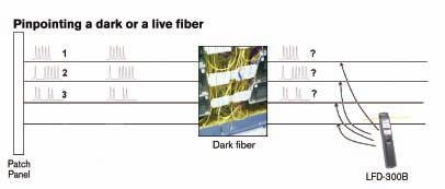
92 90 EXFO Distributed Antenna System
93 Figures 47 Test scenarios using the FiberFinder test kit OTDR and iolm These instruments are often the first considered in troubleshooting situations. As mentioned in section 3.1 Construction, one of the advantages offered by testing techniques based on reflectometry is that they perform mapping of the fiber being tested. The capacity to quickly obtain the distance to the fault (find a bad connector, fiber break or splice) is critical in troubleshooting situations where the network is down and the network owner (e.g., the neutral host provider) could face SLA penalties from the service provider. Distributed Antenna System EXFO 91
94 4.2 Troubleshooting Process The troubleshooting process recommended below is simply one example of the different steps a technician could follow to solve fiber-related issues in a DAS environment. 1- Identify and located the defective fiber. 2- Isolate the defective element: a. The transmitter (Tx) does not provide enough power. b. The fiber has exaggerated loss. c. The receiver (Rx) is not working properly. 92 EXFO Distributed Antenna System
95 4.2.1 Fiber Troubleshooting Once the faulty fiber pair has been identified, the first step is to validate the output power of the transmitters. Indoor antenna END B C-UL-B Rx Extension Unit/Hub Coax Fiber THIRD FLOOR C-DL-B Technician Conduit RF source (fiber or coax) SECOND FLOOR APC connector FTB-1 with power meter FIRST FLOOR END A Uplink C-DL-A Tx Host Unit/Main Hub RF source from BTS GROUND LEVEL Downlink C-UL-A BASEMENT LEVEL Figure 48 Power measurement at the Rx location Distributed Antenna System EXFO 93
96 If the powers are as per specification, the problem is than mostlikely related to the fiber. To save time troubleshooting the issue on the fiber, we recommend using an iolm (or OTDR), which will provide loss/reflectance information for all of the elements on the fiber, and also pinpoint any element that fails the system requirements. Indoor antenna END B C-UL-B Rx Extension Unit/Hub Coax Fiber THIRD FLOOR C-DL-B Technician Conduit RF source (fiber or coax) SECOND FLOOR APC connector APC launch/receive box 150 m FIRST FLOOR END A Uplink C-DL-A Tx Host Unit/Main Hub RF source from BTS GROUND LEVEL Downlink C-UL-A BASEMENT LEVEL Figure 49 Connecting the receive fiber at the Rx 94 EXFO Distributed Antenna System
97 To fully characterize each element (including the far-end connectors), the technician should connect a receive fiber, as shown in Figure 49, and then proceed to the Tx location. Once at the Tx location, the technician should connect the launch fiber as shown in Figure 50, and then perform the iolm (OTDR) test. Indoor antenna END B C-UL-B Rx Extension Unit/Hub Coax Fiber THIRD FLOOR C-DL-B Conduit RF source (fiber or coax) SECOND FLOOR APC connector FTB-1 with iolm APC launch/receive box 150 m FIRST FLOOR END A Uplink GROUND LEVEL Downlink C-DL-A C-UL-A Tx Host Unit/Main Hub RF source from BTS Technician BASEMENT LEVEL Figure 50 Performing the iolm (OTDR) test from the Tx Distributed Antenna System EXFO 95
98 Once the test is completed, you can refer to the result sections for information about the fault potentially present on the fiber. The table below lists a few of the faults that could lead to system failure. Type of Fault Diagnostic Solving the Issue Bad connector The connector or bulkhead is damaged, dirty or not well connected. Inspect and clean as needed. Macrobend Excessive fiber bend Inspect the fiber in this area for excessive bending. Use of a VFL could help identify the exact location of the macrobend. Bad splice Excessive loss of a non-reflective fault Inspect the splice at this location, and respliced if needed. Use of a VFL could help identify the exact location of a bad splice. Table 13 Type of fault 96 EXFO Distributed Antenna System
99 5.0 Test Documentation Although network test documentation facilitates the planning and expansion of network capacity (bandwidth and routing), most often the need for documentation is only considered when an actual problem occurs. However, when the network is down, productivity is usually lost, meaning that customers/clients may not receive support, which could in turn lead to high loss of revenue. Having network documentation readily available enables the team in charge of resolving the issue to gain an understanding of the network while minimizing the time needed to fix it, thus translating into lower costs for you and your customers. However, good documentation is not only useful when a problem occurs; it also facilitates internal and external transfer of knowledge. Another aspect to consider is that a lot of networks are built by contractors or subcontractors, who usually have to provide test reports in order to complete the job and to receive pay. It is therefore mandatory for them to save the test results of the work performed in the field. At times, measurements gathered in the field will not require extra post-processing, but in most cases extra processing will be needed in order to perform proper analysis, establish accurate diagnoses, and ultimately document (test report or birth certificate) the network appropriately, as per customer requirements or the network owner s standard. The three logical steps (Table 12) in data post-processing generally consist of editing, analyzing and documenting the test results. Distributed Antenna System EXFO 97
100 1. Edit 2. Analyze 3. Document Adjust the cable and fiber parameters (e.g., job information) Perform OTDR or iolm bidirectional analysis Report customization Add/remove OTDR-iOLM events Detect duplicated measurements Various report types Adjust detection thresholds Perform manual measurements on OTDR files Set pass/fail thresholds Table 14 Data post-processing actions Easily identify the results that fail network requirements Combined reports such as: Fiber characterization iolm with connector inspection results Performing the three steps outlined above on hundreds of measurements can be real challenge if your tools are not integrated (different software for different measurement types), or do not have batch processing capabilities. To help decrease the time spent on data processing, EXFO has developed FastReporter 2, which supports various measurement types, and offers batch capabilities and specialized reports (see figure 52). As such, FastReporter 2 can help cut reporting time in half in comparison to other reporting tools. 98 EXFO Distributed Antenna System

101 Figure 51 iolm and FIP Report Distributed Antenna System EXFO 99
FIP-400B Fiber Inspection Probe FULLY AUTOMATED INSPECTION TOOL WITH EMBEDDED ANALYSIS
 FULLY AUTOMATED INSPECTION TOOL WITH EMBEDDED ANALYSIS 2014 ANALYSIS SOFTWARE GLOBAL PORTABLE FIBER OPTIC TEST EQUIPMENT MARKET LEADERSHIP AWARD This intelligent and automated test tool transforms fiber
FIP-400B Fiber Inspection Probe FULLY AUTOMATED INSPECTION TOOL WITH EMBEDDED ANALYSIS
 FULLY AUTOMATED INSPECTION TOOL WITH EMBEDDED ANALYSIS ANALYSIS SOFTWARE 2014 GLOBAL PORTABLE FIBER OPTIC TEST EQUIPMENT MARKET LEADERSHIP AWARD This intelligent ent and automated test tool transforms
The Road to Single Mode: Direction for choosing, installing and testing single mode fiber
 The Road to Single Mode: Direction for choosing, installing and testing single mode fiber Adrian Young Leviton Network Solutions Jim Davis Fluke Networks Adrian Young, Sr. Applications Engineer Leviton
We will look first at the cable, and then the transceivers (which act as both transmitter and receiver on each end of the fiber cable).
.") Nuclear Sensors & Process Instrumentation Fiber Cable Basics Fiber-optic communication is a method of transmitting information from one place to another by sending light through an optical fiber. The light
Nuclear Sensors & Process Instrumentation Fiber Cable Basics Fiber-optic communication is a method of transmitting information from one place to another by sending light through an optical fiber. The light
Field Testing and Troubleshooting of PON LAN Networks per IEC Jim Davis Regional Marketing Engineer Fluke Networks
 Field Testing and Troubleshooting of PON LAN Networks per IEC 61280-4 Jim Davis Regional Marketing Engineer Fluke Networks Agenda Inspection and Cleaning APC vs UPC PON basics Wavelengths Architecture
MPS Webinar Technical Series
 MPS Webinar Technical Series Making Connections: Navigating Fiber Optic Cabling and Interconnection Requirements microwave photonic systems Expand Your RF Horizons Introduction Microwave Photonic Systems
Datasheet: MultiFiber Pro
 Datasheet: MultiFiber Pro First MPO tester to support both Singlemode and Multimode MPO fiber testing Data centers are growing, fueled by the proliferation of media, virtualization and the need for more
OLP-87/87P. SmartClass Fiber PON Power Meter and Microscope
 OLP-87/87P SmartClass Fiber PON Power Meter and Microscope The Viavi Solutions OLP-87 is an FTTx/PON power meter for use in qualifying, activating, and troubleshooting B-PON, E-PON, G-PON, and next-generation,
Fiber Optic Testing. The FOA Reference for Fiber Optics Fiber Optic Testing. Rev. 1/31/17 Page 1 of 12
 Fiber Optic Testing Testing is used to evaluate the performance of fiber optic components, cable plants and systems. As the components like fiber, connectors, splices, LED or laser sources, detectors and
Instalaciones de fibra optica en entornos de centro de datos y campus para suportar 40, 100G y mas
 Instalaciones de fibra optica en entornos de centro de datos y campus para suportar 40, 100G y mas Jim Davis Regional Marketing Engineer Fluke Networks Agenda Inspection and Cleaning Loss Budgets TIA (Cabling)
T-BERD /MTS-4000 Platform OLP-4057 PON Selective Power Meter Module
 COMMUNICATIONS TEST & MEASUREMENT SOLUTIONS T-BERD /MTS-4000 Platform OLP-4057 PON Selective Power Meter Module Key features The market s first BPON/EPON/GPON power meter module Selective FTTx power meter
Selection of a cable depends on functions such as The material Singlemode or multimode Step or graded index Wave length of the transmitter
 Fibre Optic Communications The greatest advantage of fibre cable is that it is completely insensitive to electrical and magnetic disturbances. It is therefore ideal for harsh industrial environments. It
Viavi T-BERD 5800 CPRI Testing Guide with ALU BBU Emulation
 Viavi T-BERD 5800 CPRI Testing Guide with ALU BBU Emulation Scope Version 4 January 2018 Firmware 26.0.0.6c1973b or Later REQUIRED! This document describes Common Public Radio Interface (CPRI) testing
Datasheet: MultiFiber Pro Update
 Datasheet: MultiFiber Pro Update Datasheet: MultiFiber Pro Update First MPO tester to support both Singlemode and Multimode MPO fiber testing Data centers are growing, fueled by the proliferation of media,
HoW confident are You about Your connector cleanliness?
 HoW confident are You about Your connector cleanliness? Gwennaël Amice, Senior Application Engineer Vincent Racine, Product Line Manager, Francis Audet, Advisor, CTO Offi ce, François Marcotte, Senior
Advanced Test Equipment Rentals ATEC (2832)
") Established 1981 Advanced Test Equipment Rentals www.atecorp.com 800-404-ATEC (2832) Datasheet: MultiFiber Pro Optical Power Meter and Fiber Test Kits Data centers are growing, fueled by the proliferation
Established 1981 Advanced Test Equipment Rentals www.atecorp.com 800-404-ATEC (2832) Datasheet: MultiFiber Pro Optical Power Meter and Fiber Test Kits Data centers are growing, fueled by the proliferation
Effects of ESD and Cleaning on SFP Fiber Optic Transceivers
 Effects of ESD and Cleaning on SFP Fiber Optic Transceivers Field Service & GSC Training DOC1928793 MR Service Engineering Imagination at work Overview Optical Modules or SFP (small form-factor pluggable)
SSA Fibre-Optic Extender 160 Fibre Installation Guidelines Version 1.2
 SSA Fibre-Optic Extender 160 Version 1.2 0.1 Introduction This document provides information on the specification and installation of optical fibre networks to support SSA optical extender products. SSA
XCOM1002JE (8602JE) Optical Receiver Manual
 Optical Receiver Manual") XCOM1002JE (8602JE) Optical Receiver Manual - 2 - 1. Product Summary XCOM1002JE (8602JE) outdoor optical receiver is our latest 1GHz optical receiver. With wide range receiving optical power, high output
XCOM1002JE (8602JE) Optical Receiver Manual - 2 - 1. Product Summary XCOM1002JE (8602JE) outdoor optical receiver is our latest 1GHz optical receiver. With wide range receiving optical power, high output
L-Band Fiber Optic Link
 One Jake Brown Road Old Bridge, NJ 08857-1000 USA (800) 523-6049 (732) 679-4000 FAX: (732) 679-4353 www.blondertongue.com INSTRUCTION MANUAL L-Band Fiber Optic Link For Direct Broadcast Satellite Distribution
Datasheet: SimpliFiber Pro
 Datasheet: SimpliFiber Pro Datasheet: SimpliFiber Pro SimpliFiber Pro makes testing simple Fluke Networks' SimpliFiber Pro Optical Power Meter incorporates new and innovative features to give technicians
Optical Design Manufacturing, Inc. Sprint 2.5. Alcatel-Lucent (ALU) Fiber Inspection and Testing Procedures. Technical Support Document
 Fiber Inspection and Testing Procedures. Technical Support Document") Optical Design Manufacturing, Inc. Sprint 2.5 Alcatel-Lucent (ALU) Fiber Inspection and Testing Procedures Technical Support Document 2 Table of Contents I. Introduction... 3 II. Test Site Overview...
Optical Design Manufacturing, Inc. Sprint 2.5 Alcatel-Lucent (ALU) Fiber Inspection and Testing Procedures Technical Support Document 2 Table of Contents I. Introduction... 3 II. Test Site Overview...
Introduction to Fibre Optics
 Introduction to Fibre Optics White paper White Paper Introduction to Fibre Optics v1.0 EN 1 Introduction In today s networks, it is almost impossible to find a network professional who has never been in
PM-240-MTP Multifiber Optical Power Meter INSTRUCTION MANUAL
 PM-240-MTP Multifiber Optical Power Meter INSTRUCTION MANUAL Revision:1.0 is registered trademark of OPTOKON, a.s. Other names and trademarks mentioned herein may be the trademarks of their respective
Optical Receiver Manual. Transmitter OP-OR112R JⅢ. Shenzhen Optostar Optoelectronics Co., Ltd (Version 2)
") Optical Receiver Manual Transmitter OP-OR112R JⅢ Shenzhen Optostar Optoelectronics Co., Ltd 2016. 7(Version 2) 1. Summary OP-OR112RJⅢ optical receiver is our latest 1GHz FTTB optical receiver. With wide
Optical Receiver Manual Transmitter OP-OR112R JⅢ Shenzhen Optostar Optoelectronics Co., Ltd 2016. 7(Version 2) 1. Summary OP-OR112RJⅢ optical receiver is our latest 1GHz FTTB optical receiver. With wide
OTLT / OTLR 3000 Manual. L-Band Fiber Optic Link MHz INSTRUCTION MANUAL
 OTLT / OTLR 3000 Manual L-Band Fiber Optic Link 850-3000 MHz INSTRUCTION MANUAL Phone: (209) 586-1022 (800) 545-1022 Fax: (209) 586-1026 E-Mail: sales@olsontech.com REV. X1 www.olsontech.com 05/12/06 INSTALLATION
OLS Series Light Sources, OPM Series Optical Power Meters, and Related Test Kits User s Guide
 OLS Series Light Sources, OPM Series Optical Power Meters, and Related Test Kits User s Guide Limited Warranty One Year Limited Warranty All Noyes products are warranted against defective material and
Optical Receiver Manual. Transmitter OP-OR212JSE. Shenzhen Optostar Optoelectronics Co., Ltd (Version 2)
") Optical Receiver Manual Transmitter OP-OR212JSE Shenzhen Optostar Optoelectronics Co., Ltd 2016. 7(Version 2) 1. Summary OP-OR212JSE optical receiver is the latest 1GHz dual-way switch optical receiver.
Optical Receiver Manual Transmitter OP-OR212JSE Shenzhen Optostar Optoelectronics Co., Ltd 2016. 7(Version 2) 1. Summary OP-OR212JSE optical receiver is the latest 1GHz dual-way switch optical receiver.
Cable Jacket - The outermost layer of the fiber cable. Application: Types Single mode Multi mode. Simplex or Duplex available
 Fiber Optic Products FIBER OPTIC PRODUCTS FIBER OPTIC PATCH CORD CABLE The Construction of a Fiber-Optic Cable Cable Jacket - The outermost layer of the fiber cable. Strengthening fibers - The strengthening
Datasheet: CertiFiber Pro Optical Loss Test Set
 Datasheet: CertiFiber Pro Optical Loss Test Set The CertiFiber Pro is the Tier 1 (basic) fiber certification solution and part of the Versiv Cabling Certification product family. The Versiv line also includes
Versiv makes you money every time you use it.
 Datasheet: CertiFiber Pro Optical Loss Test Set The CertiFiber Pro is a Tier 1 (basic) fiber certification solution and part of the Versiv Cabling Certification product family. The Versiv line also includes
Model GS Port Node 1 GHz with 65/86 MHz split
 Model GS7000 4-Port Node 1 GHz with 65/86 MHz split The Model GS7000 4-Port Node is our latest generation 1 GHz optical node platform and utilizes a completely new housing designed for optimal heat dissipation.
OPERATIONS GUIDE OWL
 t T h Optical Wavelength Laboratories OPERATIONS GUIDE MICRO OWL 2 OPTICAL POWER METER Model Numbers: MO-2 MO-2V Opt ic l a a W v e le n g t h L a b o ra t o r ie s - - n e m ip u q E t s e T OWL r e ib
AXS-200/350 OPTICAL LOSS TEST SET. part of the SharpTESTER Line LAN Applications
 OPTICAL LOSS TEST SET AXS-200/350 part of the SharpTESTER Line LAN Applications NETWORK TESTING OPTICAL Features/Benefits Straightforward step-by-step loss testing wizard Clear, LED-based pass/fail assessment
Datasheet: CertiFiber Pro Optical Loss Test Set
 Datasheet: CertiFiber Pro Optical Loss Test Set The CertiFiber Pro is a Tier 1 (basic) fiber certification solution and part of the Versiv Cabling Certification product family. The Versiv line also includes
SECTION 4 TABLE OF CONTENTS
 Contents Introduction LC, SC and ST Series...4-2 Markets and Applications...4-2 International Standard Documents Compliance...4-2 LC Series Features and Benefits...4-3 LC Standard... 4-4 to 4-5 LC for
Tech Breakfast: Fibre Optic Cabling
 Tech Breakfast: Fibre Optic Cabling An introduction phil.crawley@jigsaw24.com @IsItBroke on Twitter http://www.root6.com/author/phil Fibre optic cabling Applications within Film & TV Single mode vs. Multi
OP940. Insertion Loss & Return Loss Meter Instruction Manual. (Also supports the OP725 Integration)
") Insertion Loss & Return Loss Meter Instruction Manual (Also supports the OP725 Integration) www.optotest.com 1.805.987.1700 Contacting OptoTest Corporation 1.805.987.1700 (7:30 a.m. to 5 p.m. PST) www.optotest.com
Insertion Loss & Return Loss Meter Instruction Manual (Also supports the OP725 Integration) www.optotest.com 1.805.987.1700 Contacting OptoTest Corporation 1.805.987.1700 (7:30 a.m. to 5 p.m. PST) www.optotest.com
Measuring RL on Short Cables: A Detailed Approach
 Measuring on Short Cables: A Detailed Approach Overview In the 1990s, a new method of testing return loss revolutionized the fiber optics industry. Requiring no mandrels or matching gel to measure the
Introduction to Fiber Optic Cable Technology Jerry Bednarczyk, PE Course Content
 Introduction to Fiber Optic Cable Technology Jerry Bednarczyk, PE Course Content Page 1 of 10 GENERAL A fiber optic cable system is very similar to a copper wire system in that it is used to transmit data
Automated Connector Processing Tackles Exploding FTTP Connector Market
 Automated Connector Processing Tackles Exploding FTTP Connector Market By Joyce Kilmer and Duane Dinkel Sagitta Inc 7 Oser Avenue Hauppauge, NY 11788 Tel: 631 952 9440 Fax: 631 952-9144 www.sagitta.com
HI-DEX PRODUCT SET DATASHEET
 APPLICATION HI-DEX is an ultra high-performance, pre-terminated and modular optical fibre cabling system based on MT ferrule connector technology. This product set is designed for installationn in the
Model OTDV Broadcast Transport Links OPERATING MANUAL
 Model OTDV-1250 Broadcast Transport Links OPERATING MANUAL 24926 Highway 108 Sierra Village, CA 95346 Phone: (800) 545-1022 Fax: (209 586-1022 Rev. X5 E-Mail: sales@olsontech.com 02/23/10 Table of Contents
MTS/T-BERD Platforms WDMPMD Module
 ACTERNA TEST & MEASUREMENT SOLUTIONS MTS/T-BERD Platforms WDMPMD Module Key Features A unique solution combining OSA, PMD, and SA test functions in one plug-in module The most compact PMD/WDM/SA test solution
Datasheet: CertiFiber Pro Optical Loss Test Set
 Datasheet: CertiFiber Pro Optical Loss Test Set Datasheet: CertiFiber Pro Optical Loss Test Set The CertiFiber Pro is a Tier 1 (basic) fiber certification solution and part of the Versiv Cabling Certification
T-BERD /MTS-6000, -6000A and Platforms OFI Multifunction Loss Test Module
 COMMUNICATIONS TEST & MEASUREMENT SOLUTIONS T-BERD /MTS-6000, -6000A and -8000 Platforms OFI Multifunction Loss Test Module Key Features One-button automated testing, including continuity check, bidirectional
Sidelighter TM Optical distance to fault measurement module
 Sidelighter TM Optical distance to fault measurement module Available only at: Sidelighter TM Introducing the latest in optical fiber measurements and versatility Artisan Laboratories Corporation s hand
The current state of multimode OTDR and Light Source and Power Meter (LSPM) Insertion Loss (IL) testing is as follows:
 Insertion Loss (IL) testing is as follows:") APPLICATION NOTE Meeting the Encircled Flux Launch Standard Scope: Guidance on how to test to the Encircled Flux (EF) multimode launch standard using existing optical test equipment and the Optronics Encircled
APPLICATION NOTE Meeting the Encircled Flux Launch Standard Scope: Guidance on how to test to the Encircled Flux (EF) multimode launch standard using existing optical test equipment and the Optronics Encircled
Job Aid Server and CSS Separation Avaya S8700 Media Server
 Overview of server separation Job Aid and CSS Separation Avaya S8700 Media This job aid provides information regarding the separation of S8700 Media s and the Separation of duplicated Center Stage Switch
DESIGN!!GUIDELINES!!!!!
 DESIGNGUIDELINES 1 2 3 4 5 6 7 8 9 10 11 12 13 14 15 16 17 18 19 20 21 22 23 24 25 26 27 28 29 30 31 32 33 34 35 36 37 38 39 40 41 42 43 44 45 46 1. Testing General 1.1. For acceptance, 100% of the media
Gigabit Multi-mode SX to Single Mode LX Converter. User s Manual NGF-728 Series. Warning COPYRIGHT
 COPYRIGHT Gigabit Multi-mode SX to Single Mode LX Converter User s Manual NGF-728 Series All rights reserved. No part of this publication may be reproduced, stored in a retrieval system, or transmitted
CC-Link IE Controller Network Compatible. CC-Link IE Controller Network Recommended Network Wiring Parts Test Specifications
 Model Title CC-Link IE Controller Network Compatible CC-Link IE Controller Network Recommended Network Wiring Parts Specifications Management number: BAP-C0401-028-A CC-Link Partner Association (1/31)
FIBER QUICKMAP. Users Manual. Multimode Troubleshooter
 FIBER QUICKMAP Multimode Troubleshooter Users Manual January 2011, Rev. 1 7/11 2011 Fluke Corporation. All rights reserved. All product names are trademarks of their respective companies. LIMITED WARRANTY
Fibre Optic Cable & Connector Guide
 Fibre Optic Cable & Connector Guide White paper White Paper Fibre Optic Cable & Connector Guide v1.0 EN 1 Introduction Organising through cables and connectivity options can be an exasperating exercise.
Delaware County Community College Project # Marple Campus Renovation - Phase % Construction Documents November 23, 2011
 SECTION 271323 - COMMUNICATIONS OPTICAL FIBER BACKBONE CABLING PART 1 - GENERAL 1.1 DESCRIPTION A. This section provides the specifications for the work related to the optical fiber system in the project.
User Manual CXE800. Fibre Optic Receiver. CXX Series. Teleste Corporation
 Broadband Cable Networks August 30, 2007 1(8) CXX Series User Manual Teleste Corporation CXE800 Fibre Optic Receiver Broadband Cable Networks August 30, 2007 2(8) Introduction The CXE800 is a unidirectional,
Assembly code page 46. Cable code page 47. Assembly classes page 48. Polarization maintaining assemblies page 52
 cable assemblies Assembly code page 46 Cable code page 47 Assembly classes page 48 Polarization maintaining assemblies page 52 45 Assembly: Ordering code Description cable type 27H01CD0- see cable code
InterReach Fusion Data Sheet
 In-Building Wireless Networking System InterReach Fusion offers the same superior performance as Unison in a multiband, easy-to-install, economical package. It is ideal for mid-sized to large installations
SPECIAL SPECIFICATION 6191 Fiber Optic Cable
 2004 Specifications CSJ 0014-02-014, etc SPECIAL SPECIFICATION 6191 Fiber Optic Cable 1. Description. Furnish, install, splice, field terminate, and test the fiber optic cables. 2. Materials. A. General
Public Works Division Lighting District Fiber Optic Specifications April 2009
 Public Works Division Lighting District Fiber Optic Specifications April 2009 7000 Florida Street Punta Gorda, Florida 33950 Tele: 941.575.3600 Fax : 941.637.9265 www.charlottecountyfl.com/publicworks
OpticalProducts. Illuminating Your Network. Testing the World s Networks
 OpticalProducts Illuminating Your Network Testing the World s Networks Fibre Optic Testers Ease of use and cost-effectiveness Trend s Family of Optical Products Has Increased The new products include Optical
3A+G Technology & Turnkey Production Solution XFS COMMUNICATIONS, INC.
 3A+G Technology & Turnkey Production Solution BY XFS COMMUNICATIONS, INC. 1 Influence of Connectors Attenuation on Fiber Network Performance The larger the attenuation, the greater the decrease in power
SPECIAL SPECIFICATION 2284 Fiber Optic Cable (Self-Supporting)
") 2004 Specifications CSJ 0086-14-046 SPECIAL SPECIFICATION 2284 Fiber Optic Cable (Self-Supporting) 1. Description. Furnish, install, splice, field terminate, and test the fiber optic cables. 2. Materials.
2004 Specifications CSJ 0086-14-046 SPECIAL SPECIFICATION 2284 Fiber Optic Cable (Self-Supporting) 1. Description. Furnish, install, splice, field terminate, and test the fiber optic cables. 2. Materials.
OPTICAL POWER METER WITH SMART DETECTOR HEAD
 OPTICAL POWER METER WITH SMART DETECTOR HEAD Features Fast response (over 1000 readouts/s) Wavelengths: 440 to 900 nm for visible (VIS) and 800 to 1700 nm for infrared (IR) NIST traceable Built-in attenuator
Pre-bid Supplement #01 Communications Specifications and Additional Scope Project Bid: CM Date: 05/26/2017
 Pre-bid Supplement #01 Communications Specifications and Additional Scope Project Bid: CM-2017-2 Date: 05/26/2017 Additional specification information for data communication to cameras and between Library
White Paper. Fibre Optic Technologies for Satellite Communication and Broadcast Industries. By Tom Lacey Applications Engineering Group PPM Ltd, UK
 White Paper Fibre Optic Technologies for Satellite Communication and Broadcast Industries By Tom Lacey Applications Engineering Group PPM Ltd, UK Abstract The satellite communications and broadcast industries
COE Group plc. Contents
 CWDM Supplement COE Group plc COE develops and supplies analogue and digital video surveillance (CCTV) systems for complex and robust applications. These end to end systems include fibre transmission,
Bravo AV s Structured or Whole-House Wiring Approach
 Custom Audio & Video Systems: Design and Installation Bravo AV s Structured or Whole-House Wiring Approach THE QUALITY OF THE CABLE YOU USE IS CRITICALLY IMPORT TO THE PERFORMANCE OF YOUR SYSTEM Introduction
Spec Sheet. InterReach Fusion Wideband 2.5 GHz WiMAX. In-Building Wireless Networking System. Product Highlights
 In-Building Wireless Networking System InterReach Fusion is the latest addition to ADC s portfolio of Distributed Antenna Systems. It offers the same superior performance as Unison in an easy-to-install,
VersiVision. FVTM4BCxA-CE / FVRM4BCxA-CE MULTIPLEXER SYSTEM 4-CHANNELS DIGITALLY ENCODED VIDEO 2-CHANNELS BI-DIRECTIONAL DATA
 VersiVision FVTM4BCxA-CE / FVRM4BCxA-CE MULTIPLEXER SYSTEM 4-CHANNELS DIGITALLY ENCODED VIDEO 2-CHANNELS BI-DIRECTIONAL DATA 4-CHANNELS BI-DIRECTIONAL AUDIO 4-CHANNELS BI-DIRECTIONAL CONTACT CLOSURE 1-CHANNEL
SPECIAL SPECIFICATION 6559 Telecommunication Cable
 2004 Specifications CSJ 0015-09-147, etc. SPECIAL SPECIFICATION 6559 Telecommunication Cable 1. Description. This specification governs the materials, installation, termination, splicing, testing, training,
SatellitePlus Model OLAT/OLAR. Advanced L-Band Series. 10-4,000 MHz OPERATING MANUAL
 SatellitePlus Model OLAT/OLAR Advanced L-Band Series 10-4,000 MHz OPERATING MANUAL 24926 Highway 108 Sierra Village, CA 95346 Phone: (800) 545-1022 Fax: (209 586-1022 025-000570 Rev. X7 E-Mail: sales@olsontech.com
Fibre Channel Fiber-to-Fiber Media Converters
 Fibre Channel Fiber-to-Fiber Media Converters CN-155-XX CN-131-XX Multi-mode to Single-mode series Single-mode to Single-mode series Low cost CCN-2000 Fibre Channel media converter modules by Canary Communications
OPERATOR MANUAL OSD351 FIBRE OPTIC CCTV TRANSMITTER CARD
 OPERATOR MANUAL OSD351 FIBRE OPTIC CCTV TRANSMITTER CARD OSD351 FIBRE OPTIC CCTV TRANSMITTER CARD Document No:10103701 PAGE 2 C O N T E N T S 1. TECHNICAL SUMMARY...4 1.1 BRIEF DESCRIPTION...4 1.2 TECHNICAL
To select a fibre optic cable, you have to make choices of the fibre selection and the cable construction selection.
 Fibre Optic Cables & Connectors Guide Introduction Organising through cables and connectivity options can be an exasperating exercise. It's tough enough working through the categories and levels of copper
100g cfp Health check Jean-Marie Vilain, Product Specialist, Transport and Datacom
 100g cfp Health check Jean-Marie Vilain, Product Specialist, Transport and Datacom As the deployment of 100G links continues to gather steam, the demand for increased bandwidth is at an all-time high and
User Manual CXE Rev (12) CXX Series. User Manual. Teleste Corporation CXE810. Fibre optic receiver
 CXX Series. User Manual. Teleste Corporation CXE810. Fibre optic receiver") 27.3.2012 1(12) CXX Series User Manual Teleste Corporation CXE810 Fibre optic receiver 27.3.2012 2(12) Contents Introduction... 3 Installation... 3 Housing... 3 Powering... 4 Interfaces... 4 Fibre installation...
27.3.2012 1(12) CXX Series User Manual Teleste Corporation CXE810 Fibre optic receiver 27.3.2012 2(12) Contents Introduction... 3 Installation... 3 Housing... 3 Powering... 4 Interfaces... 4 Fibre installation...
Module 11 : Link Design
 Module 11 : Link Design Lecture : Link Design Objectives In this lecture you will learn the following Design criteria Power Budget Calculations Rise Time Budget Calculation The optical link design essentially
FiberLink 3500 Series Transceivers
 MANUAL FiberLink 3500 Series Transceivers 2 or 4 Channel 3G/HD/SD-SDI Transmission over one or two single mode or multimode fibers Installation and Operations Manual WWW.ARTEL.COM Contents Contents Welcome...
Prisma Optical Networks Ancillary Modules
 Optoelectronics Prisma Optical Networks Ancillary Modules Description The Prisma platform is capable of utilizing a combination of modules which address a variety of revenue generating applications. The
MAXCOM PRODUCT SPECIFICATIONS FIBER OPTIC VIDEO / AUDIO / ASI LINK. Model MX3257HD. Description. Features. Model Selection Guide
 MAXCOM PRODUCT SPECIFICATIONS FIBER OPTIC VIDEO / AUDIO / ASI LINK Model MX3257HD Description The rack-mountable MX3257HD fiber optic video multiplexer is ideal for transmitting 1 channel of video, 2 channels
Overcoming Nonlinear Optical Impairments Due to High- Source Laser and Launch Powers
 Overcoming Nonlinear Optical Impairments Due to High- Source Laser and Launch Powers Introduction Although high-power, erbium-doped fiber amplifiers (EDFAs) allow transmission of up to 65 km or more, there
Product Catalogue. Fiber Optic Assemblies & Adapters. Table of Contents General Description... 2
 Product Catalogue Fiber Optic Assemblies & Adapters Table of Contents 1. General Description... 2 2. Connectors... 3 2.1 SC/UPC... 3 2.2 SC/APC... 3 2.3 FC/UPC... 3 2.4 FC/APC... 3 2.5 ST/UPC... 3 2.6
Connectix Cabling Systems
 Connectix Cabling Systems Cabling Standards and CPR Update Connectix CEP Fibre Optic Solutions Jason Holroyd CNID Director of Business Development Types of fibre Agenda Introduction Uses Construction Transmission
OPERATOR MANUAL OSD553 TRIPLE VIDEO FIBRE OPTIC RECEIVER
 OPERATOR MANUAL OSD553 TRIPLE VIDEO FIBRE OPTIC RECEIVER OSD553 TRIPLE VIDEO FIBRE OPTIC RECEIVER Document No: 101035 Revision 02 PAGE 2 C O N T E N T S 1. TECHNICAL SUMMARY... 4 1.1 BRIEF DESCRIPTION...
ISO/IEC testing LC to LC (Duplex Multimode) DTX-MFM
 DTX-MFM") Page 1 of 5 ISO/IEC 14763-3 testing LC to LC (Duplex Multimode) DTX-MFM ISO/IEC 11801 now refers fibre testing to ISO/IEC 14763-3. More importantly, the limits have changed and we'll show you how in this
Page 1 of 5 ISO/IEC 14763-3 testing LC to LC (Duplex Multimode) DTX-MFM ISO/IEC 11801 now refers fibre testing to ISO/IEC 14763-3. More importantly, the limits have changed and we'll show you how in this
Cisco GS7000 High-Output 4-Way Segmentable Node with 42/54 Split
 Data Sheet Cisco GS7000 High-Output 4-Way Segmentable Node with 42/54 MHz Split The Cisco GS7000 High-Output Segmentable Node with 42/54 MHz Split is the latest-generation 1-GHz optical node platform designed
Fiber Optics Redefined
 Fiber Optics Redefined Questions and Answers on the basics of fiber optic installation TECHLOGIX NETWORX Questions & Answers Questions and Answers Q: What are the two main types of fiber? A: The two main
SPECIAL SPECIFICATION :1 Video (De) Mux with Data Channel
 Mux with Data Channel") 1993 Specifications CSJ 0924-06-223 SPECIAL SPECIFICATION 1160 8:1 Video (De) Mux with Data Channel 1. Description. This Item shall govern for furnishing and installing an 8 channel digital multiplexed
1993 Specifications CSJ 0924-06-223 SPECIAL SPECIFICATION 1160 8:1 Video (De) Mux with Data Channel 1. Description. This Item shall govern for furnishing and installing an 8 channel digital multiplexed
MICROSENS. Fast Ethernet Switch Modul 4x 10/100Base-TX, 1x 100Base-FX. Description. Features
 Fast Ethernet Switch Modul 4x 10/100Base-TX, 1x 100Base-FX Description This Ethernet Switch Module has been designed with 4x10/100Base-TX ports and 1x100Base-FX fiber optic port for the interconnection
SPECIAL SPECIFICATION 8540 Telecommunication Cable
 2004 Specifications CSJ 0914-00-307 & CSJ 0914-25-003 SPECIAL SPECIFICATION 8540 Telecommunication Cable 1. Description. This specification governs the materials, installation, termination, splicing, testing,
FiberLink 3350 Series
 MANUAL FiberLink 3350 Series 3G/HD/SD-SDI Transmission over one single mode or multimode fiber Installation and Operations Manual WWW.ARTEL.COM Contents Contents Welcome....3 Features....3 Package Contents....3
FiberLink 3355 Series
 MANUAL Link 3355 Series 3G/HD/SD-SDI to DVI Optical Receiver Installation and Operations Manual WWW.ARTEL.COM Contents Contents Welcome....3 Features....3 Package Contents....3 Technical Specifications
How to Speak Fiber Geek Article 4: Single-Mode Optical Fiber Geometries
 Welcome back, Fiber Geeks! The first article in this series highlighted some bandwidth demand drivers and introductory standards information. Article 2 then focused on attenuation and Article 3 followed
OPERATOR MANUAL OSD8865 DIGITAL TRIPLE VIDEO FIBER OPTIC RECEIVER
 OPERATOR MANUAL OSD8865 DIGITAL TRIPLE VIDEO FIBER OPTIC RECEIVER INDEX 1 1 TECHNICAL SUMMARY... 4 1.1 BRIEF DESCRIPTION... 4 1.1.1 OVERVIEW... 4 1.1.2 APPLICATIONS... 4 1.1.3 FEATURES AND BENEFITS...
DVBus and Multiplexer and demultiplexer assemblies for video channels, with bidirectional audio and data USER MANUAL
 DVBus 8350-16 and 8350-4 Multiplexer and demultiplexer assemblies for 16-4 video channels, with bidirectional audio and data USER MANUAL 1. Description. Indicators and system connections DVBus 8350 systems
SLS-50 Stabilized Laser Source. User s Manual. Shineway Technologies, Inc. All rights reserved.
 SLS-50 Stabilized Laser Source User s Manual Shineway Technologies, Inc. All rights reserved. Safety Instructions The WARNING sign denotes a hazard. It calls attention to a procedure, practice, or the
OFI Optical Fiber Identifier User s Guide
 OFI Optical Fiber Identifier User s Guide OFI Optical Fiber Identifier User s Guide 2002-2008, AFL Telecommunications, all rights reserved. OFI1-11-1000 Revision A, 05.02.08 Specifications are subject
Cable Certification. General Testing Criteria (Applies to all cable certification testing) Attachment E Cable Certification
 Attachment E Cable Certification") General Testing Criteria (Applies to all cable certification testing) 1. RCIT reserves the right to be present during any or all cable testing procedures. The Contractor shall obtain authorization from
General Testing Criteria (Applies to all cable certification testing) 1. RCIT reserves the right to be present during any or all cable testing procedures. The Contractor shall obtain authorization from
FTTH & FITH. Discreet optical fiber solutions from the network connection point to the set-top box.
 FTTH & FITH Discreet optical fiber solutions from the network connection point to the set-top box www.omelcom.com FIBER: THE FUTURE IS HERE The past several years have seen major progress in the penetration