LeRIBSS MTC MANUAL. Issue #1. March, MTC Control Unit Definitions, Information and Specifications. MTC Control Unit Electronic Schematics
|
|
|
- Adelia Montgomery
- 5 years ago
- Views:
Transcription
1 LeRIBSS MTC MANUAL Issue #1 March, 2008 Contents: MTC Control Unit MTC Control Unit Definitions, Information and Specifications Programming the MTC Control Unit Program Parameters Initial Setup Measuring Out a Load of Tape Comment on Length of Tape Loading Tape Splicing Tape Hardware Note MTC Control Unit Electronic Schematics A CD Containing This Manual The MTC Control Unit Input/Output Specifications The MTC Control Unit Electronic Diagrams The MTC Control Unit Electronic Connections 1

 for some possible unusual situation. The event counter counts the number of moves.")
2 MTC Control Unit Most of the labeling is self-explanatory. The unit is operated in the local mode when installing new tape and testing the system. Then, the local start initiates the program. When in the remote mode, an external start will initiate the program. The drive fault occurs when the motor is unable to turn properly, i.e. the tape is jammed. The in motion out can be connected to an oscilloscope to measure the move time. The remote enable and remote out connections are not really necessary, but are provided (just in case) for some possible unusual situation. The event counter counts the number of moves. It resets to zero when the power is off. The elapsed time represents the time since the last move. The program select switch has 2


3 4 positions, each of which represents a different move sequence. The move programs are accessed by the laptop computer. This is explained in the next section. Once these programs are set, the laptop is no longer needed. The laptop s only function is to alter the programs denoted by 0, 1, 2, and 4. The tape sensor connection goes to the back of the MTC. If the tape breaks, the tape break light is lighted and the drive motor is disabled until the tape is fixed or the tape sensor disable connector is installed. This is shown in the photo below. This plug is also needed whenever the aluminized mylar tape is used since it is semitransparent and the tape-break diodes will be energized. In that case, however, it is not possible to know when/if the tape breaks. Since the Black Watch tape will be used almost exclusively, this plug will not be used very often, except occasionally for testing purposes. The back of the drive unit contains the connections to the drive motor, to the computer and a connector to temporarily attach the remote start/stop switch. This switch is used only during tape loading procedures. It must be removed when that operation is completed. 3
4 MTC Control Unit Definitions, Information, and Specifications This table is also contained on the enclosed CD titled Front_Panel Front Panel Event Counter Counter Counts the number of tape moves. Resets on power off. Elapsed Time Timer Counts the time between moves. Resets when a move begins and restarts after the move. Program select Rotary Switch Selects which Index to execute in the Ultraware software. Program 0 = index 1 Program 1 = index 2 Program 2 = index 4 Program 4 = index 8 Drive must be disabled and reenabled after changing programs for the new selection to take affect. Tape Break Red LED Indicates that one of the tape sensors has been tripped and the drive is Tape Sensor Input 4 Pin Lemo Tape Break Out Output BNC disabled. Connection to the tape sensors. If not connected, a broken tape fault will disable the drive 5 volt TTL High when broken tape fault is present, low otherwise. Enable Amber LED Indicates that the drive is enabled. Drive Enable Toggle Switch When the Local/Remote switch is in the Local position, Drive Enable switch enables and disables the drive. When the Local/Remote switch is in Remote position, this switch has no function. Enable Out Output BNC 5 volt TTL signal. High when drive is enabled, low otherwise. Remote Enable Input BNC Input that remotely enables the drive when the Remote/Local switch is in the Remote position. High to enable. In Motion Amber LED Indicates that the motor is in motion. In Motion Out Output BNC 5 volt TTL signal. High when drive is in motion, low otherwise Fault Reset Push Button Clears Faults associated with the motor and drive. Will not clear a broken tape fault. 4

5 Drive Fault Out Output BNC 5 volt TTL signal. High when a Drive fault is present (does not indicate broken tape faults). Local Start Push Button When the Local/Remote Switch is in the Local position, Local Start switch starts the index corresponding to the program select switch. When the Local/Remote switch is in the Remote position, the button has no function. Local/Remote Toggle Switch When in Local, Enable and Start commands are controlled by the front Panel. When in Remote, control is via the Remote Enable and External Start BNC s. External Start Input BNC Input that remotely starts the index corresponding to the program select switch when the Local/Remote switch is in the Remote position. Min 2 msec positive TTL pulse. Programming the MTC Control Unit Attach the laptop to the drive unit using the USB to RS232 cable. Initialize the Allen- Bradley Ultraware program. 5

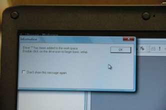
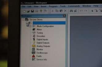
6 Cancel OK Open Open Mode Configuration 6


7 Open Indexing There are 64 different index slots. While they can all be used in programmatic ways, only four (4) are loaded into the control unit. These are index numbers 1, 2, 4, and 8. 7
8 The correspondence between index number and program number is: Program Parameters Index # = 2 program # Thus Index 1 = Program 0 Index 2 = Program 1 Index 4 = Program 2 Index 8 = Program 3 Mode: Distance: Incremental Units are in counts x 10-3 cm/count 7.80 x 10⁻⁴ in/count 505 counts/cm 1282 counts/in 7692 counts = 6.0 inches counts = 12.0 inches counts = 18.0 inches Batch Count: 1 Dwell: Velocity: The time between moves. Units in milliseconds. The speed after acceleration is over. Units in RPM. Note: For short moves this essentially plays no role for the accelerations and decelerations used here because there is no flat spot on the curve (see below). Acceleration: Units Rev/s 2 8
 or with the tension device disabled (remove spring and let rest on bottom), but then the")
9 Deceleration: Units Rev/s 2 The Tension Device was designed for a maximum acceleration of 200 rev/s 2. Accelerations above this value can be used when the moves are longer than 12 inches (a rough number) or with the tension device disabled (remove spring and let rest on bottom), but then the registration of the tape is not accurate. This would be OK for the take-away mode. If accelerations greater than 200 rev/s 2 are used in the move and count mode, then the thicker pressure block must be utilized. Examples of these various settings are given below. The Tension Device was designed for a maximum deceleration of 200 rev/s 2. Decelerations above this value can be used when the moves are longer than 12 inches (a rough number) or with the tension device disabled (remove spring and let rest on bottom), but then the registration of the tape is not accurate. This would be OK for the take-away mode. Next Index: Sends the program to the specified index number. Action When Complete: Tells program what to do next. Initial Setup Index #1 (Program 0) The settings are shown below. This is the set-up for the tape-loading procedure. 9

10 Note that the distance is just set for a long move (1,000,000 counts or 780 inches) and then the next index sends it back to the top and the Action When Completed tells it to send it back immediately. The dwell is set to zero so there is no time between. The net result is a continuous move of the tape. Index #2 (Program #1) This is the setup for a move of 18 inches or 46 cm (distance = 23,077 counts) with one second between moves (Dwell = 1000 ms). Velocity will have an effect here. This will be discussed below. The setup below is well within the design parameters, and results in a move time of 238 ms. However, this is a longer move and as stated above, longer moves can sustain greater accelerations and decelerations. Keeping all else constant, one can get the following move times: Velocity (RPM) acceleration (rev/s 2 ) deceleration (rev/s 2 ) move time (ms) The precision of the location of the activity spot becomes less with the greater accelerations. It is recommended that the thicker pressure block be utilized 10
 This is the setup for a move of 12 inches or 30 cm (distance = 15,385 counts) with one second between moves (Dwell = 1000 ms).")
11 above 200 rev/s 2 if precision on the spot is required. Index #4 (Program #2) This is the setup for a move of 12 inches or 30 cm (distance = 15,385 counts) with one second between moves (Dwell = 1000 ms). The setup below is within the design parameters, and results in a move time of 198 ms. Keeping all else constant, one can get the following move times: Velocity (RPM) acceleration (rev/s 2 ) deceleration (rev/s 2 ) move time (ms) The precision of the location of the activity spot becomes less with the greater accelerations. It is recommended that the thicker pressure block be utilized above 200 rev/s 2 if precision on the spot is required. Index #8 (Program #3) This is the setup for a move of 6 inches or 15 cm (distance = 7,692 counts) with one second between moves (Dwell = 1000 ms). Velocity will not have an effect here. The setup below is results in a move time of 138 ms. 11

12 Keeping all else constant, one can get the following move times: Velocity (RPM) acceleration (rev/s 2 ) deceleration (rev/s 2 ) move time (ms) Remove Spring in Tension Device for the following setups Measuring out tape 12


13 Install a reel of tape on the spool mount. Thread the tape through the unit as shown in the figure below. Let the leader hang into a clean cardboard box. Set the counter to zero and start cranking tape into the box. The counter records in 0.01 units per foot. Thus one foot is 100 units. 300 feet would be 30,000 on the counter. Measure out 300 feet of tape, cut it, and tape the end to the outside of the cardboard box fore easy retrieval. Comment on length of tape: Long moves, on the order of 2 feet or more, pack into the cassette in such a way that 400 to 500 feet of tape could be used. For the short moves required at HRIBF, however, the packing is such that a smaller amount of tape is called for. To be safe, limit the amount of Black Watch tape to approximately 300 feet. If other tapes are used, then one should determine the maximum length empirically. 13

14 Loading Tape 1. Using the tape measuring device, measure out 300 feet of tape and spool it carefully into a clean cardboard box. Be sure to Scotch-tape the end of the tape to the side of the box so that it does not get lost in the pile of tape. 2. Remove the cover from the tape cassette. It is fastened with vented screws. Vented screws are not necessary in this application since venting is provided on the side, but they are preferred. 3. Remove the PEEK block that puts tension on the rubber pressure wheel. The standard PEEK block is inches thick. This is set for the Black Watch tape. For high accelerations, use the thicker block. Two other blocks are provided if/when thicker tape is utilized. 4. Cut off an 8 foot piece of tape from the spool and begin to thread it from the inside of the cassette into the drive mechanism. 14


15 5. Use the rubber pressure wheel (PEEK block removed) to help you catch and pull the tape into the mechanism. NOTE: This is the only time you can reverse the direction of the tape when the pressure wheel is engaged. You can use the PEEK block to support the pressure wheel off the drive wheel if you want to push/pull the tape in either direction. 6. Thread the tape around the small drive wheel and out of the box. This may require the use of a small tool since there is little room. A small wooden stick about the thickness of a thick toothpick would work best. 7. Holding the pressure wheel up off the drive wheel (use Peek block) pull out enough tape so that the tape leader can reach the box containing the 300 feet of tape. 8. Attach the leader to the tape in the box. Attach it so that the metallic side of the tape will see the beam. Scotch tape will work here. You can overlap the tapes with the tape, but be sure to trim the edges to make the width ½ inch. 9. Pull the fresh tape into the tape cassette box and start to thread it out of the box at the bottom of the box. 15


16 10. Now pull about 2 feet of tape out of the box, but take care not to leave much tape inside the box as it may twist. Continue to thread the tape around the pulley A and upward to the tension device. 11. This part requires the most dexterity. The tape goes through the narrow slot in the guide and around the tension pulley. BUT, the wheel with O-ring tires presses on the tension pulley. These pulleys can be held apart by manually separating their axels marked axels. It is spring loaded so it will return to its original position when released. Thread the tape back down to pulley B, then upward and around pulley C and then out of the cassette. The tape path should then look like this : 16


17 12. Now, replace the cassette cover. Load the 300 feet of tape into the cassette using the following procedure: a) Plug the remote start/stop switch into the back of the tape drive unit. 17
 While your left hand guides the tape and keeps out twists, your right hand stands ready to stop the drive if necessary. e) Load all the tape but leave enough out to make the splice.")
18 b) Set to program 0. c) With a cotton glove on your left hand, hold the tape coming out of the box in your left hand and the remote start/stop switch in your right. Start the drive. d) While your left hand guides the tape and keeps out twists, your right hand stands ready to stop the drive if necessary. e) Load all the tape but leave enough out to make the splice. You will splice the end of the tape from the box to the leader that comes out of the bottom of the KF-50 exit port. 13. Splice the tape according to the recommended procedure (see next section). 14. Take the slack out of the tape hanging out of the MTC and let it run for awhile on program Check the path and operation. Stop the drive and comb the carbon brushes so that the tape runs smoothly over a maximum of the fibers. 16. Set to program 1, 2, or 4 (the one to be used in the experiment) and watch the operation. Let it run for 5-10 minutes. If all looks OK, stop and close the door and proceed to vacuum. Tape Splicing The equipment items needed to make a proper splice are shown below. NOTE: A good splice will enable you to run the entire experiment without a tape break. A bad splice will cost a lot of time. Follow these procedures diligently. 18
19 a) Wash your hands. b) Overlap the ends and cut through both at the same time at an angle of about 30 degrees. c) Clean both ends with alcohol using Kim-Wipes or something similar. Wipe both ends with a clean Kim-Wipe. Take care not to touch the ends. d) Cut two pieces of the ¾ inch wide, inch thick aluminized mylar tape. One to 1.5 inches long is OK. Stick each on the side of the MTC (at a corner of the mylar tape which will not be used in the splice itself). e) Place one end of the tape in the tape guide such that the 30 degree cut is centered in the gap left for the mylar tape. Place the other tape into the guide so the 30 degree cuts match up. They should not touch. You should see a tiny bit of space between them (a few thousands of an inch). Be SURE you have no twists in the tape and that metallic side matches metallic side. f) Place a piece of mylar tape over them and press down. Flip the connected tape over and place the other piece of Mylar tape over the splice. Using the roller, roll both sides on the plexiglass roller block. g) Trim the edges so that the splice is ½ inch or slightly less. Be absolutely sure there are no edges sticking out. The edges should be smooth to the touch as you run your finger over them. The curved scissors may be useful if a small snip is needed. h) Roll both sides again on the block. i) Using the yellow plastic handle and the plexiglass block, rub each side with the handle so that you run from the center of the splice outward toward the edge of the mylar tape. Never go backwards. You want to press the Mylar tape edge down firmly onto the MTC tape. You have 4 regions to do this procedure. CAUTION. Hold tension on the tape when you do this. If you put a kink or crease in the tape you should start over. Hardware Notes The standard PEEK pressure block is inches thick. This is appropriate for the Black Watch tape and accelerations 200 rev/s2 or less when using the move and count mode of operation 19
20 The standard spring that suspends the tension device is 1.35 inches long. A variety of other sizes are provided and can be tried. The secret is that there should always be tension in the tape. If it is loose all the time (there often is an occasional loose move), then a spring change may solve the problem. 20
21 Front Panel Event Counter Counter Counts the number of tape moves. Resets on power off. Elapsed Time Timer Counts the time between moves. Resets when a move begins and restarts after the move. Program select Rotary Switch Selects which Index to execute in the Ultraware software. Program 0 = index 1 Program 1 = index 2 Program 2 = index 4 Program 4 = index 8 Drive must be disabled and reenabled after changing programs for the new selection to take affect. Tape Break Red LED Indicates that one of the tape sensors has been tripped and the drive is Tape Sensor Input 4 Pin Lemo Tape Break Out Output BNC disabled. Connection to the tape sensors. If not connected, a broken tape fault will disable the drive 5 volt TTL High when broken tape fault is present, low otherwise. Enable Amber LED Indicates that the drive is enabled. Drive Enable Toggle Switch When the Local/Remote switch is in the Local position, Drive Enable switch enables and disables the drive. When the Local/Remote switch is in Remote position, this switch has no function. Enable Out Output BNC 5 volt TTL signal. High when drive is enabled, low otherwise. Remote Enable Input BNC Input that remotely enables the drive when the Remote/Local switch is in the Remote position. High to enable. In Motion Amber LED Indicates that the motor is in motion. In Motion Out Output BNC 5 volt TTL signal. High when drive is in motion, low otherwise Fault Reset Push Button Clears Faults associated with the motor and drive. Will not clear a broken tape fault. Drive Fault Out Output BNC 5 volt TTL signal. High when a Drive fault is present (does not indicate broken tape faults). Local Start Push Button When the Local/Remote Switch is in 21
22 the Local position, Local Start switch starts the index corresponding to the program select switch. When the Local/Remote switch is in the Remote position, the button has no function. 22
High Performance (Gold Plus) Spliceable Tape Feeder Part Number: Part Number: Revision 3 Jun 2008 No.
 Spliceable Tape Feeder Part Number: Part Number: Revision 3 Jun 2008 No.") 8mm High Performance (Gold Plus) Spliceable Tape Feeder Part Number: 50934707 12mm High Performance (Gold Plus) Spliceable Tape Feeder Part Number: 50934807 Revision 3 Jun 2008 No. 0930D-E010 i Table
8mm High Performance (Gold Plus) Spliceable Tape Feeder Part Number: 50934707 12mm High Performance (Gold Plus) Spliceable Tape Feeder Part Number: 50934807 Revision 3 Jun 2008 No. 0930D-E010 i Table
High Performance DL-60 (Gold Plus) (7 in - 13 in) Dual Lane Spliceable Tape Feeder Part Number: Revision 3 Sep No.
 (7 in - 13 in) Dual Lane Spliceable Tape Feeder Part Number: Revision 3 Sep No.") 8mm High Performance DL-60 (Gold Plus) (7 in - 13 in) Dual Lane Spliceable Tape Feeder Part Number: 50381212 Revision 3 Sep. 2010 No. 0730D-E043 Page i Table of Contents Functional Description...1 Procedures
8mm High Performance DL-60 (Gold Plus) (7 in - 13 in) Dual Lane Spliceable Tape Feeder Part Number: 50381212 Revision 3 Sep. 2010 No. 0730D-E043 Page i Table of Contents Functional Description...1 Procedures
Instruction Manual for Electronic Blowers and Flashboards
 Instruction Manual for Electronic Blowers and Flashboards These instructions cover both the table model 17212 table top Electronic Bingo Blower (Fig 1) and the 17213 floor model Electronic Bingo Blower
Caution. Hanging the Screen:
 Installation Instructions for Laminar and Laminar XL Projection Screens Caution 1. Read Instructions through completely before proceeding; keep them for future reference. Follow these instructions carefully.
D1.6 Audio Cassette Special Processing Guide
 D1.6 Audio Cassette Special Processing Guide Summary Most audio cassettes are playable in their current condition. This guide contains procedures for fixing cassette tapes which are not playable due to
Variwrap Controller Manual
 Variwrap Controller Manual Operation The controller has two operating modes Manual and Auto. The mode is changes by pressing the (F1) Auto/Manual button. The mode setting is displayed in the top right
Auxiliary states devices
 22 Auxiliary states devices When sampling using multiple frame states, Signal can control external devices such as stimulators in addition to switching the 1401 outputs. This is achieved by using auxiliary
Setup Guide. Read me BefoRe unpacking!
 Setup Guide Read me BefoRe unpacking! Package Contents In The Replicator package The Replicator SD card (in The Replicator SD card slot) In the Accessory Box found within The Replicator frame Single or
3. Electronics and MMU2 unit assembly
 Written By: Jakub Dolezal 2018 manual.prusa3d.com/ Page 1 of 34 Step 1 Tools necessary for this chapter Please prepare tools for this chapter: 2.5mm Allen key for M3 screws 2mm Allen key for nut alignment
Troubleshooting Guide for E-Poll Book
 Troubleshooting Guide for E-Poll Book CHANGING USERS ON THE E-POLL BOOK Changing Users on the E-poll Book 1. Tap Return to Main button on the voter search screen. 2. Tap on the Manage Polls tab in the
EAGLE RE-1 CONTROLLER
 EAGLE RE-1 CONTROLLER For Use On ALL MotoSAT Mounts Supported Systems HD SL5 DirecTV HD DP3 Dish Network HD SC2 SHAW HD DP3 BELL TV EXECUTIVE 18" DirecTV 101 Dish Network 119 MSC-60 SHAW MD-500 Dish Network
Business Display Solutions - Institutional Television Mirror TV. Installation Guide for 32PM8822 ( BDL3221M) 42PM8822 (BDL4221M)
 42PM8822 (BDL4221M)") Business Display Solutions - Institutional Television P.O. Box 218, 5600 MD Eindhoven, The Netherlands 32-42 Mirror TV Installation Guide for 32PM8822 ( BDL3221M) 42PM8822 (BDL4221M) Date: October 2005
Business Display Solutions - Institutional Television P.O. Box 218, 5600 MD Eindhoven, The Netherlands 32-42 Mirror TV Installation Guide for 32PM8822 ( BDL3221M) 42PM8822 (BDL4221M) Date: October 2005
Part names (continued) Remote control
 Remote control") Introduction Part names (continued) Remote control (1) STANDBY ( 25) (1) (2) ON ( 25) (3) (3) ID - 1 / 2 / 3 / 4 s ( 18) (4) (4) COMPUTER 1 ( 27) (7) (5) COMPUTER 2 * (8) (6) COMPUTER 3 * (10) (13) (7)
Introduction Part names (continued) Remote control (1) STANDBY ( 25) (1) (2) ON ( 25) (3) (3) ID - 1 / 2 / 3 / 4 s ( 18) (4) (4) COMPUTER 1 ( 27) (7) (5) COMPUTER 2 * (8) (6) COMPUTER 3 * (10) (13) (7)
4.9 BEAM BLANKING AND PULSING OPTIONS
 4.9 BEAM BLANKING AND PULSING OPTIONS Beam Blanker BNC DESCRIPTION OF BLANKER CONTROLS Beam Blanker assembly Electron Gun Controls Blanker BNC: An input BNC on one of the 1⅓ CF flanges on the Flange Multiplexer
Safety Information. Camera System. If you back up while looking only at the monitor, you may cause damage or injury. Always back up slowly.
 Table of Contents Introduction...3 Safety Information...4-6 Before Beginning Installation...7 Installation Guide...8 Wiring Camera & Monitor...9-10 Replacement Installation Diagram...11 Clip-On Installation
DX-10 tm Digital Interface User s Guide
 DX-10 tm Digital Interface User s Guide GPIO Communications Revision B Copyright Component Engineering, All Rights Reserved Table of Contents Foreword... 2 Introduction... 3 What s in the Box... 3 What
Assembling and Mounting the Presentation Display, Speakers, Speaker Screens, and Table Door
 CHAPTER 8 Assembling and Mounting the Presentation Display, Speakers, Speaker Screens, and Table Door July 13, 2012, This document provides you with the procedures you perform to assemble and mount the
8mm PrecisionPro (Green) DL Spliceable 7-13 Tape Feeder. T Rev. B hd This document supports assembly Rev. -
 DL Spliceable 7-13 Tape Feeder. T Rev. B hd This document supports assembly Rev. -") 8mm PrecisionPro (Green) DL Spliceable Tape Feeder 8mm PrecisionPro (Green) DL Spliceable Tape Feeder 8mm PrecisionPro (Green) DL Spliceable Tape Feeder 8mm PrecisionPro (Green) DL Spliceable 7-13 Tape
8mm PrecisionPro (Green) DL Spliceable Tape Feeder 8mm PrecisionPro (Green) DL Spliceable Tape Feeder 8mm PrecisionPro (Green) DL Spliceable Tape Feeder 8mm PrecisionPro (Green) DL Spliceable 7-13 Tape
EAGLE RE-1 CONTROLLER For Use On MotoSAT HD Mounts
 EAGLE RE-1 CONTROLLER For Use On MotoSAT HD Mounts Supported Systems HD SL5 DirecTV HD DP3 Dish Network HD SC2 SHAW HD DP3 BELL TV EXECUTIVE DirecTV 101 Dish Network 119 MSC-60 SHAW MD-500 Dish Network
A Motor can be in many groups, by assigning additional channel# on it.
 Timer Remote Control Instruction How to use the channel numbers - There are 32 channels on the Remote Control Timer you can assign to Curtain Motor(s). To operate the Motors individually by itself only,
SP02 Series Tape Feeder. Operator Guide. All rights reserved Revision 1 29 Feb D-E36
 SP02 Series Tape Feeder SP02 Series Tape Feeder Operator Guide All rights reserved Revision 1 29 Feb 08 380D-E36 This page intentionally left blank. SP02 Series Tape Feeders Operator Guide Hover-Davis,
Outback STX. User Guide Supplement. Parts List. STX Terminal Overview
 Outback STX User Guide Supplement This supplement details the following changes from STX v1.0 to STX v1.1: Parts List below STX Terminal Overview below Connection Diagram on page 2 AC110 Power Up and Power
PSC300 Operation Manual
 PSC300 Operation Manual Version 9.10 General information Prior to any attempt to operate this Columbia PSC 300, operator should read and understand the complete operation of the cubing system. It is very
Summit Systems Sound Board Modification
 Summit Systems Sound Board Modification The Summit slots fitted with the music feature play two sounds; one when the coin is inserted, and the other that plays as winning coins pass through the hopper
Procedure: Procedures: DIME TEAM: Drop # (circle one) Date: In Lab (either on Level 4, Level 6, or in shop): Installation: Functional Check
 Date: In Lab (either on Level 4, Level 6, or in shop): Installation: Functional Check") Procedure: Red Experiment specific Black - General In Lab (either on Level 4, Level 6, or in shop): Installation: 1. Wear safety goggles when working with the experiment. 2. Perform experiment-specific
Procedure: Red Experiment specific Black - General In Lab (either on Level 4, Level 6, or in shop): Installation: 1. Wear safety goggles when working with the experiment. 2. Perform experiment-specific
IPad 3 (glass) REPAIR GUIDE. Version Edition
 REPAIR GUIDE. Version Edition") IPad 3 (glass) REPAIR GUIDE Version 1 2016 Edition IPad 4 REPAIR GUIDE LCD AND DIGITIZER REPLACEMENT RiAna Soto Repair Training Specialist rsoto@cellairis.com FOR EVERY REPAIR MAKE SURE TO COMPLETE, INITIAL,
IPad 3 (glass) REPAIR GUIDE Version 1 2016 Edition IPad 4 REPAIR GUIDE LCD AND DIGITIZER REPLACEMENT RiAna Soto Repair Training Specialist rsoto@cellairis.com FOR EVERY REPAIR MAKE SURE TO COMPLETE, INITIAL,
Blown Film Extrusion. Line Control. 5 Layers CD Series IBC Temperature USER MANUAL
 Blown Film Extrusion Line Control 5 Layers CD Series IBC Temperature USER MANUAL P.O.B. 1122 Afula Illit 18550, Israel Tel: +972-4-6405857 Fax: +972-4-6405911 info@sysmetric-ltd.com Manual Number: 5CDIT102
1-Touch Vibratory Sieve Shaker SS-10
 1-Touch Vibratory Sieve Shaker SS-10 Safety Instructions WARNING!! This machine operates on electric current. Improper operation could result in electrical shock, electrocution, or an explosion! 1. ALWAYS
PCM-24 Press Feed Controller
 PCM-24 Press Feed Controller Information furnished by EMERSON EMC is believed to be accurate and reliable. However, no responsibility is assumed by EMERSON EMC for its use. EMERSON EMC reserves the right
COPYRIGHT NOVEMBER-1998
 Application Notes: Interfacing AG-132 GPS with G-858 Magnetometer 25430-AM Rev.A Operation Manual COPYRIGHT NOVEMBER-1998 GEOMETRICS, INC. 2190 Fortune Drive, San Jose, Ca 95131 USA Phone: (408) 954-0522
NOTICE: This document is for use only at UNSW. No copies can be made of this document without the permission of the authors.
 Brüel & Kjær Pulse Primer University of New South Wales School of Mechanical and Manufacturing Engineering September 2005 Prepared by Michael Skeen and Geoff Lucas NOTICE: This document is for use only
Capstone Experiment Setups & Procedures PHYS 1111L/2211L
 Capstone Experiment Setups & Procedures PHYS 1111L/2211L Picket Fence 1. Plug the photogate into port 1 of DIGITAL INPUTS on the 850 interface box. Setup icon. the 850 box. Click on the port 1 plug in
TracVision R6DX Installation Guide
 TracVision R6DX Installation Guide These instructions explain how to install the TracVision R6DX satellite TV antenna system on an RV or motor coach. Complete instructions on how to use the system are
Aurora Grid-Tie Installation Instructions (Model Number: PVI-3.0-OUTD-US-W) Revision 4.1
 Revision 4.1") Aurora Grid-Tie Installation Instructions (Model Number: PVI-3.0-OUTD-US-W) Revision 4.1 Contents 1) Grid-Tie Installation Block Diagram... 3 2) Installation Steps.... 4 2.1) Initial Setup.... 4 2.1.1)
Aurora Grid-Tie Installation Instructions (Model Number: PVI-3.0-OUTD-US-W) Revision 4.1 Contents 1) Grid-Tie Installation Block Diagram... 3 2) Installation Steps.... 4 2.1) Initial Setup.... 4 2.1.1)
EDL8 Race Dash Manual Engine Management Systems
 Engine Management Systems EDL8 Race Dash Manual Engine Management Systems Page 1 EDL8 Race Dash Page 2 EMS Computers Pty Ltd Unit 9 / 171 Power St Glendenning NSW, 2761 Australia Phone.: +612 9675 1414
IEFIS G3 Inputs, outputs and Alarms
 IEFIS G3 Inputs, outputs and Alarms Document version: 2, May 2016 User manual on the use and configuration of the analog and digital inputs and digital outputs as well as Alarm setup and use. Related equipement:
INPUT OUTPUT GAIN DELAY. Hue Candela Strobe Controller. Hue Candela s STROBE CONTROLLER. Front Panel Actual Size 7 ¼ By 4 ¾ POWER. msec SEC 10 1.
 Hue Candela s STROBE CONTROLLER INPUT OUTPUT ON TIME POWER NO B C A GAIN X LOCK Y OUT Z Hue Candela Strobe Controller 4 5 6 7..... 8. 3. 9. 2 10.. 1 11. STEP m.. 0 10 1. 10 10 1.0 10 zero DELAY. 03. 02.
MachineryMate 800 operating guide Handheld vibration meter
 MachineryMate 800 operating guide Handheld vibration meter Wilcoxon Sensing Technologies 20511 Seneca Meadows Parkway, Germantown MD 20876, USA Amphenol (Maryland), Inc d/b/a Wilcoxon Sensing Technologies
Operating Instructions
 CNTX Contrast sensor Operating Instructions CAUTIONS AND WARNINGS SET-UP DISTANCE ADJUSTMENT: As a general rule, the sensor should be fixed at a 15 to 20 angle from directly perpendicular to the target
Electric Motorized Projection Screen Spectrum Tab-Tension Series User s Guide
 Electric Motorized Projection Screen Spectrum Tab-Tension Series User s Guide Important Safety Precautions Make sure to read this user s guide and follow the procedures below prior to screen operation.
Electric Motorized Projection Screen PowerMax Tension Series
 Electric Motorized Projection Screen PowerMax Tension Series User s Guide Important Safety & Warning Precautions Make sure to read this user s guide and follow the procedures below. Caution: The screen
Part No. ENC-LAB01 Users Manual Introduction EncoderLAB
 PCA Incremental Encoder Laboratory For Testing and Simulating Incremental Encoder signals Part No. ENC-LAB01 Users Manual The Encoder Laboratory combines into the one housing and updates two separate encoder
1. Play the tape until you hear the first cue, that is, the sound at the beginning of the section you intend to remove.
 Tape Editing Cut editing (also known as destructive editing) consists of physically cutting magnetic recording tape, removing an unwanted portion and rejoining the recording tape with a special adhesive
Instruction Manual for the & Electronic Bingo Blower
 Instruction Manual for the 17212 & 17214 Electronic Bingo Blower The directions in this manual when referring to the 17212 are referring to software version 2.83 (you can find what version your blower
IPad 4 REPAIR GUIDE. Version Edition
 IPad 4 REPAIR GUIDE Version 1 2016 Edition IPad 4 REPAIR GUIDE LCD AND DIGITIZER REPLACEMENT RiAna Soto Repair Training Specialist rsoto@cellairis.com FOR EVERY REPAIR MAKE SURE TO COMPLETE, INITIAL, AND
Field Test Procedure for Sentry. 1 Purpose Applicable documents Procedure Duration - Time Estimate... 2
 Title: File : 50053-1B--FIELD-TEST.DOCX Field Test Procedure for Sentry Page: 1 of 37 Table of Contents: 1 Purpose... 2 2 Applicable documents... 2 3 Procedure Duration - Time Estimate... 2 3.1 10048 (ARM&12CHBriteSpot)...
Mounting a Scintillation Detector
 Mounting a Scintillation Detector Dietrech Z. Washington Some general remarks: (1) Be careful when handling the photomultiplier and the plastic scintillator. Handling the plastic scintillator with bare
SonoruS Audio. ATR10 Analog Tape Reproducer. Operating Manual
 SonoruS Audio ATR10 Analog Tape Reproducer Operating Manual 1 OPERATING INSTRUCTIONS FOR THE SonoruS ATR10 IMPORTANT NOTES Protect your tape deck from excessive heat and humidity. Install it in a manner
Special Applications Modules
 (IC697HSC700) datasheet Features 59 1 IC697HSC700 a45425 Single slot module Five selectable counter types 12 single-ended or differential inputs TTL, Non-TTL and Magnetic Pickup input thresholds Four positive
Operational specification of Scanreco HANDY handheld transmitter
 Operational specification of Scanreco HANDY handheld transmitter Page 1 of 7 1. Pushbuttons......... 3 1.1. Transmitter start up... 3 2. Mode description......... 4 2.1. Operational mode... 4 2.2. Operational
IRIG-B PTP Clock Converter Output Module Hardware Installation Manual
 IRIG-B PTP Clock Converter Output Module Hardware Installation Manual Kyland Technology Co., LTD. Publication Date: May 2012 Version: V1.2 Customer Service Hotline: (+8610) 88796676 FAX: (+8610) 88796678
SMART Height Adjustable Wall Mount (HAWM-UX/UF) Integration and Cabling Guide. For SMART Board 600 and 800 interactive whiteboard projector systems
 Integration and Cabling Guide. For SMART Board 600 and 800 interactive whiteboard projector systems") SMART Height Adjustable Wall Mount (HAWM-UX/UF) Integration and Cabling Guide For SMART Board 600 and 800 interactive whiteboard projector systems Product Registration If you register your SMART product,
SMART Height Adjustable Wall Mount (HAWM-UX/UF) Integration and Cabling Guide For SMART Board 600 and 800 interactive whiteboard projector systems Product Registration If you register your SMART product,
Instruction manual. KUZMA 4POINT 14 inch TONEARM Serial Number:
 Instruction manual KUZMA 4POINT 14 inch TONEARM Serial Number:.. 2016-09 1 KUZMA LTD INSTRUCTION MANUAL FOR 4POINT 14 tonearm The 4POINT 14 tonearm is a very precisely engineered piece of equipment, however,
Snail Fence InteleCell Deployment Guide
 Snail Fence InteleCell Deployment Guide Preparation 1. Prepare deployment trip by making sure you have the following materials and tools when you fly up to the site: InteleCell NEMA Enclsoure (grey plastic
Product Manual MNX10015 / REV C MODEL SB142, SB242. Dual Output Series Switch Boxes
 Product Manual MNX10015 / REV C MODEL SB142, SB242 Dual Output Series Switch Boxes Contents Section I Overview Introduction.... 2 Description... 2 Section II Installation Mounting... 3 Electrical Connections...
Revision Protocol Date Author Company Description 1.1 May 14, Seth LOUTH Revised for formatting
 PRODUCT ADC TOPIC ODETICS TCS-2000 CART MACHINE DATE: May 14, 1999 REVISION HISTORY Revision Protocol Date Author Company Description 1.1 May 14, Seth LOUTH Revised for formatting 1999 Olitzky 1.0 Aug.
4830A Accelerometer simulator Instruction manual. IM4830A, Revision E1
 4830A Accelerometer simulator Instruction manual IM4830A, Revision E1 IM4830, Page 2 The ENDEVCO Model 4830A is a battery operated instrument that is used to electronically simulate a variety of outputs
SCREEN WINCH SYSTEM INSTALLATION MANUAL FOR SCREENS FROM 300 cm. UP TO 450 cm. of width
 SCREEN WINCH SYSTEM INSTALLATION MANUAL FOR SCREENS FROM 300 cm. UP TO 450 cm. of width Before installing the screen winch system, please read the following instructions carefully: The screen winch system
3M Cold Shrink QS-III Silicone Rubber Splice Kit 5488A-TOW/WOT
 3M Cold Shrink QS-III Silicone Rubber Splice Kit 5488A-TOW/WOT For Tape Over Wire (TOW) and Wire-Over-Tape (WOT) Shielded Cable For 250 2000 kcmil cable with 650-mil primary insulation thickness Instructions
E X P E R I M E N T 1
 E X P E R I M E N T 1 Getting to Know Data Studio Produced by the Physics Staff at Collin College Copyright Collin College Physics Department. All Rights Reserved. University Physics, Exp 1: Getting to
Interview Management System Installation Guide
 Technical Support Interview Management System Installation Guide www.casecracker.com support@casecracker.com (720) 442-7072 Technologies 2017 (v.15) 1 Equipment Checklist Box 1 Box 2 Box 3 (Optional) CaseCracker
Meetinghouse Webcast Setup Guide for the Europe Area Sending Site
 Meetinghouse Webcast Setup Guide for the Europe Area Sending Site Rev 03 15 Nov 2009 Introduction This guide provides helpful information and details for successfully setting up a webcast in the Europe
Commissioning Guide. firepickdelta. Commissioning Guide. Written By: Neil Jansen firepickdelta.dozuki.com Page 1 of 22
 firepickdelta Commissioning Guide Written By: Neil Jansen 2017 firepickdelta.dozuki.com Page 1 of 22 Step 1 Pre-Requisites Before commissioning, please make sure ALL of the following steps have been completed,
JAMAR TRAX RD Detector Package Power Requirements Installation Setting Up The Unit
 JAMAR TRAX RD The TRAX RD is an automatic traffic recorder designed and built by JAMAR Technologies, Inc. Since the unit is a Raw Data unit, it records a time stamp of every sensor hit that occurs during
Electrical connection
 Splice sensor Dimensioned drawing en 04-2014/06 50116166-01 4mm 12-30 V DC We reserve the right to make changes DS_IGSU14CSD_en_50116166_01.fm Reliable detection of splice on paper web or plastic web With
Scan-Light Supplement. Fitting instructions and hardware details For Mitsubishi MH105AG and MH216CG scanners
 Scan-Light Supplement Fitting instructions and hardware details For Mitsubishi MH105AG and MH216CG scanners Contents Contents Fitting instructions and hardware details... 1 For Mitsubishi MH105AG and MH216CG
INSTRUCTION AND MAINTENANCE VIDEO MOTORE PROJECTION SCREEN
 INSTRUCTION AND MAINTENANCE VIDEO MOTORE PROJECTION SCREEN 1.1 TECHNICAL DATA PRODUCT DESCRIPTION Screens made with the following projection fabrics: SOFT WHITE, MATT WHITE SOFT, SOFT WHITE TRANSOUND,
TV Lift System Model CL-65 Installation Instructions
 TV Lift System Model CL-65 Installation Instructions Contact: Support@Nexus21.com Toll Free: (866) 500-5438 Phone: (480) 951-6885 Fax: (480) 951-6879 Revised: 01/17/17 Below is a parts list describing
MICROMASTER Encoder Module
 MICROMASTER Encoder Module Operating Instructions Issue 01/02 User Documentation Foreword Issue 01/02 1 Foreword Qualified Personnel For the purpose of this Instruction Manual and product labels, a Qualified
CONNECTING THE FUTURE 19" LINXS LIGHTWAVE INTEGRATED CROSS-CONNECT SYSTEM USER MANUAL
 CONNECTING THE FUTURE 19" LINXS LIGHTWVE INTEGRTED CROSS-CONNECT SYSTEM USER MNUL 109003 Issue Rev 2 19" Lightwave Integrated Cross-Connect System (LINXS) User Manual Document Number 109003 Issue Rev 2
CONTROLS AND CONNECTIONS - figs. 1 & 2
 Scanned, ocr ed and converted to PDF by HansO, 2001 CONTROLS AND CONNECTIONS - figs. 1 & 2 (1) tape counter with zero reset button (2) SAVE indicator - lights up during data saving (3)DATA FLOW indicator
Installation / Set-up of Autoread Camera System to DS1000/DS1200 Inserters
 Installation / Set-up of Autoread Camera System to DS1000/DS1200 Inserters Written By: Colin Langridge Issue: Draft Date: 03 rd July 2008 1 Date: 29 th July 2008 2 Date: 20 th August 2008 3 Date: 02 nd
SBL /SBLG Series Wireless Clock
 Installation Manual V8.3 SBL /SBLG Series Wireless Clock Current as of August 2018 The Sapling Company, Inc. SBL and SBLG Series Wireless Clocks Table of Contents Table of Contents 2 Important Safety Instructions
ImproX (TRT) Twin Remote Terminal INSTALLATION MANUAL
 Twin Remote Terminal INSTALLATION MANUAL") SPECIFICATIONS MODEL NUMBER: XRT910-0-0-GB-XX XRT911-0-0-GB-XX XTT911-0-0-NN-XX IMPROX TRT ImproX (TRT) Twin Remote Terminal INSTALLATION MANUAL Working Environment XRT910-0-0-GB-XX... (Aluminium Extruded
SPECIFICATIONS MODEL NUMBER: XRT910-0-0-GB-XX XRT911-0-0-GB-XX XTT911-0-0-NN-XX IMPROX TRT ImproX (TRT) Twin Remote Terminal INSTALLATION MANUAL Working Environment XRT910-0-0-GB-XX... (Aluminium Extruded
K Service Source. Apple High-Res Monochrome Monitor
 K Service Source Apple High-Res Monochrome Monitor K Service Source Specifications Apple High-Resolution Monochrome Monitor Specifications Characteristics - 1 Characteristics Picture Tube 12-in. diagonal
SRV02-Series. Ball & Beam. User Manual
 SRV02-Series Ball & Beam User Manual Table of Contents 1. Description...3 1.1 Modular Options...4 2. System Nomenclature and Components...5 3. System Setup and Assembly...6 3.1 Typical Connections for
ASK THE EXPERTS: Procedure for Verifying Magnetic Pickup Signal Integrity Using a Windrock Portable Analyzer
 December 2016 ASK THE EXPERTS: Procedure for Verifying Magnetic Pickup Signal Integrity Using a Windrock Portable Analyzer QUESTION: Does Windrock have some standard procedures for verifying magnetic pickup
CITIZEN QUARTZ Basketball Timer. Model No. ME2XXX Cal. No. D310 INSTRUCTION MANUAL CTZ-B EXPLANATION OF DISPLAY AND BUTTONS
 CITIZEN QUARTZ Basketball Timer 3. EXPLANATION OF DISPLAY AND BUTTONS Model No. ME2XXX Cal. No. D310 INSTRUCTION MANUAL CTZ-B8003 When reading this instruction manual please keep the watch diagram in view.
K Service Source. Apple High-Res Monochrome Monitor
 K Service Source Apple High-Res Monochrome Monitor K Service Source Specifications Apple High-Resolution Monochrome Monitor Specifications Characteristics - 1 Characteristics Picture Tube 12-in. diagonal
VITALink Taped Splice Straight Through Crimp
 A Marmon Wire & Cable Berkshire Hathaway Company VITALink Taped Splice Straight Through Crimp 2 Hour Fire-Rated Splice VITALink MC Cables, UL FHIT 120 Installation Instructions Description The VITALink
TASKI Service Tool Edition: V5.10/2014
 Edition: V5.10/2014 Index 1 General 1.1 General information 1 1.1.1 Part reference 1 1.1.2 Consumable supplies 1 1.1.3 Direction description 1 1.1.4 Power source 1 1.2 Required material 2 1.2.1 Tools 2
PC-250. SMD Taped Parts Counter Operator s Manual. ISO 9001:2008 Certified. V-TEK, Incorporated 751 Summit Avenue Mankato, MN USA
 PC-250 SMD Taped Parts Counter Operator s Manual ISO 9001:2008 Certified V-TEK, Incorporated 751 Summit Avenue Mankato, MN 56001 USA (P) 507-387-2039 (F) 507-387-2257 www.vtekusa.com Dear Customer: All
USER MANUAL FOR THE ANALOGIC GAUGE FIRMWARE VERSION 1.1
 by USER MANUAL FOR THE ANALOGIC GAUGE FIRMWARE VERSION 1.1 www.aeroforcetech.com Made in the USA! WARNING Vehicle operator should focus primary attention to the road while using the Interceptor. The information
Model DT-311J. And DT-311J-230V(AC) DIGITAL STROBOSCOPE INSTRUCTION MANUAL
 DIGITAL STROBOSCOPE INSTRUCTION MANUAL") Test Equipment Depot - 800.517.8431-99 Washington Street Melrose, MA 02176 - TestEquipmentDepot.com Model DT-311J And DT-311J-230V(AC) DIGITAL STROBOSCOPE INSTRUCTION MANUAL 1. GENERAL The DT-311J DIGITAL
Test Equipment Depot - 800.517.8431-99 Washington Street Melrose, MA 02176 - TestEquipmentDepot.com Model DT-311J And DT-311J-230V(AC) DIGITAL STROBOSCOPE INSTRUCTION MANUAL 1. GENERAL The DT-311J DIGITAL
Single Axis Position Controller
 SERIES P9511 Single Axis Position Controller Compact Construction Simple Go-to operation Integrated Relay Output Integrated Mains Power Supply ELEKTRO-TRADING sp. Z o.o. 44-109 Gliwice, ul. Mechaników
COLOUR CHANGING USB LAMP KIT
 TEACHING RESOURCES SCHEMES OF WORK DEVELOPING A SPECIFICATION COMPONENT FACTSHEETS HOW TO SOLDER GUIDE SEE AMAZING LIGHTING EFFECTS WITH THIS COLOUR CHANGING USB LAMP KIT Version 2.1 Index of Sheets TEACHING
Series 1100 ColorTS Servo Manual Registration System
 Series 1100 ColorTS Servo Manual Registration System 400 Oser Avenue Hauppauge NY 11788 631 434 3700 phone 631 434 3718 fax www.empregister.com December 14, 2005 TABLE OF CONTENTS TABLE OF CONTENTS...
LCD STIMULUS DISPLAY for ENV-007/008 CHAMBERS
 instrumentation and software for research LCD STIMULUS DISPLAY for ENV-007/008 CHAMBERS ENV-132M USER S MANUAL DOC-291 Rev. 1.0 Copyright 2015 All Rights Reserved P.O. Box 319 St. Albans, Vermont 05478
SPECIFICATION NO Model 207 Automatic GTAW Welding System
 1.0 Introduction The Model 207 is a completely self-contained Gas Tungsten Arc Welding (GTAW) System requiring only input power, inert gas and AMI Welding Head (or manual torch) for operation. Its small
Aerial Cable Installation Best Practices
 Aerial Cable Installation Best Practices Panduit Corp. 2007 BEST PRACTICES Table of Contents 1.0 General... 3 2.0 Introduction... 3 3.0 Precautions... 4 4.0 Pre-survey... 5 5.0 Materials and Equipment...
Location and function of controls
 Location and function of controls 1. Motor Control Selector 9. DC INPUT SOCKET 2. PAUSE Key 10. DIN Socket 3. STOP/EJECT Key 11. RECORD Indicator (Yellow) 4. FAST FORWARD/CUE Key 12. DATA Indicator (Green)
Creative Suggestions & Billboard Installation
 TMNT CAMPAIGN LOS ANGELES, CA These instructions include creative suggestions as well as handling, installation, and dismantling step by step guides for Light Tape Billboard Installations. R R Creative
Transmitter Interface Program
 Transmitter Interface Program Operational Manual Version 3.0.4 1 Overview The transmitter interface software allows you to adjust configuration settings of your Max solid state transmitters. The following
PCM-16 Phase Synchronization Controller Operators Manual
 PCM-16 Phase Synchronization Controller Operators Manual Information furnished by EMERSON EMC is believed to be accurate and reliable. However, no responsibility is assumed by EMERSON EMC for its use.
ISE, Inc Royalton Rd. Cleveland, OH USA Tel: (440) Fax: (440) B Long Ranger Timer
 Fax: (440) B Long Ranger Timer") ISE, Inc. 10100 Royalton Rd. Cleveland, OH 44133 USA Tel: (440) 237-3200 Fax: (440) 237-1744 http://instserv.com 365B Long Ranger Timer INSTALLATION INSTRUCTION November, 2000 3-0365-095-04-00 DESCRIPTION:
ISE, Inc. 10100 Royalton Rd. Cleveland, OH 44133 USA Tel: (440) 237-3200 Fax: (440) 237-1744 http://instserv.com 365B Long Ranger Timer INSTALLATION INSTRUCTION November, 2000 3-0365-095-04-00 DESCRIPTION:
Troubleshooting the CTS 1100
 CHAPTER 7 Troubleshooting the CTS 1100 Revised: November 2011, Contents You may want to periodically test system components using the hardware and software tests available in the Cisco TelePresence System
Lesson Sequence: S4A (Scratch for Arduino)
") Lesson Sequence: S4A (Scratch for Arduino) Rationale: STE(A)M education (STEM with the added Arts element) brings together strands of curriculum with a logical integration. The inclusion of CODING in STE(A)M
Lesson Sequence: S4A (Scratch for Arduino) Rationale: STE(A)M education (STEM with the added Arts element) brings together strands of curriculum with a logical integration. The inclusion of CODING in STE(A)M
apple Service Source Apple Cinema HD Display 23" LCD (ADC) 11 April Apple Computer, Inc. All rights reserved.
 11 April Apple Computer, Inc. All rights reserved.") apple Service Source Apple Cinema HD Display 23" LCD (ADC) 11 April 2003 2003 Apple Computer, Inc. All rights reserved. apple Service Source Take Apart Apple Cinema HD Display 23" LCD (ADC) 2003 Apple
apple Service Source Apple Cinema HD Display 23" LCD (ADC) 11 April 2003 2003 Apple Computer, Inc. All rights reserved. apple Service Source Take Apart Apple Cinema HD Display 23" LCD (ADC) 2003 Apple
Operation/Reference Guide IRIS. Infrared/Serial Data Capture Unit. Control System Accessories
 Operation/Reference Guide IRIS Infrared/Serial Data Capture Unit Control System Accessories Last Revised: 1/17/2007 AMX Limited Warranty and Disclaimer All products returned to AMX require a Return Material
SAFETY WARNINGS AND GUIDELINES... 3 INTRODUCTION... 4 CUSTOMER SERVICE... 4 PACKAGE CONTENTS... 4 RECOMMENDED TOOLS... 6 CONTROL PANEL OVERVIEW...
 CONTENTS SAFETY WARNINGS AND GUIDELINES... 3 INTRODUCTION... 4 CUSTOMER SERVICE... 4 PACKAGE CONTENTS... 4 RECOMMENDED TOOLS... 6 CONTROL PANEL OVERVIEW... 6 ASSEMBLY... 7 SYSTEM RESET... 11 OPERATION...