GSCmini - Pneumatic Timer Based Valve-Gate Sequence Controller lnstruction Manual
|
|
|
- Hugo Pope
- 5 years ago
- Views:
Transcription


1 lnstruction Manual
2 CONTENTS 1. Power 4. Getting Started 2. Interface Features 5. Mode Examples 3. Mode Descriptions 6. Wiring Specifications CAUTION A minimum of one gate must be opened at the start of the injection fward (signal) (time=0sec.) with zero (0) Delay (DEL) time. Failure to do so may cause damage to the Hot Runner system. * Unit will have a facty setting: Gate 1 will be set with a default of zero (0) Delay time and 1 second Open time. Page INCOE 08/16 INCOE Cp. Global Headquarters 1740 E. Maple Road Troy, MI USA T: E: tech.suppt@incoe.com
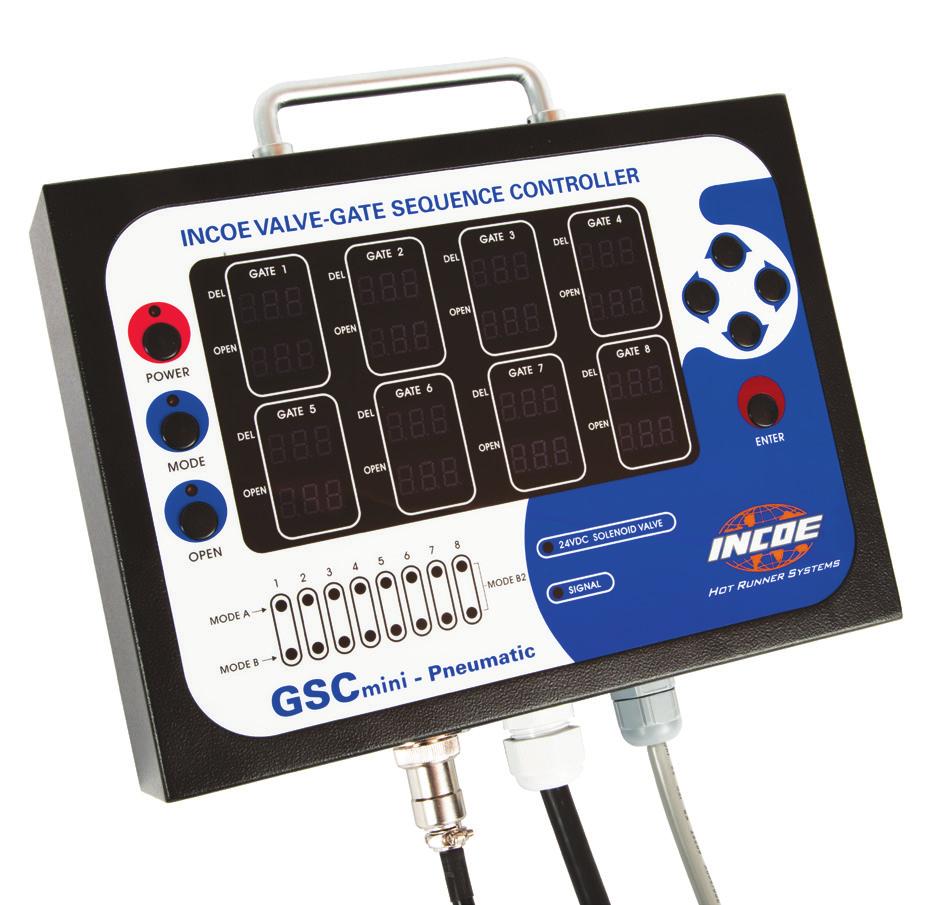
3 1. POWER A) Main Power Input: 115/120/220 VAC B) Signal Input Power: 24 VDC from Machine when Injection Fward C) Solenoid Valve Output Power: 24 VDC Less than 100mA per GATE 2. INTERFACE FEATURES Left Select 6 Machine Injection Fward/Mold 10 OPEN LED indicates the gate is open 2 Up Select Closed 24 VDC Signal Input Indicat 11 OPEN display indicates time gate 3 Right Select 7 Mode A Indicat LEDs remains open 4 Down Select 8 Mode B Indicat LEDs 12 DELAY (DEL) display indicates time 5 Ouput Voltage LED Indicat 9 Mode B2 Indicat LEDs when gate is to open 2016 INCOE 08/16 Page 3 INCOE Cp. Global Headquarters 1740 E. Maple Road Troy, MI USA T: E: tech.suppt@incoe.com
4 3. MODE DESCRIPTIONS Mode A - Able to set Delay (DEL) Time only. All gates stay open during injection signal (Mode A LEDs are illuminated). Mode B - Able to Set Delay Time and Open Time (Mode B LEDs are illuminated). Mode B2 - Able to set Delay Time, Open Time and Second Delay Time and Open Time (Both Mode A & Mode B LEDs are illuminated). Gate Off - A/B Mode LEDs, DEL /OPEN display panel off. 4. GETTING STARTED Connect Cables from GSCmini 1. Connect 24 VDC output cable to Solenoid Valve Stack. 2. Connect 24 VDC input cable to injection fward machine output. 3. Plug in unit to a 120 VAC power outlet. Power on Press Power To Select Mode 1. Press and Hold Mode f 4 seconds. Mode LED of 1st gate flashes. 2. While Mode LED is flashing press up down to scroll through mode types (A Mode B Mode B2 Mode (A & B mode LEDs will be flashing) Off (A & B flashing separately). 3. Press left right to change between gates and repeat mode selection f each gate. This must be done while displays are flashing mode function times out and Mode will need to be pressed again. 4. Keep idle f 4 seconds to automatically save. GSCmini - Pneumatic Timer Based Valve-Gate Sequence Controller To Change Unit Selection (Decimal Placement): 1. Move to Gate (1-8) using While Gate DEL Display is flashing, press and hold Mode f 4 seconds,"uni" (Unit) displays in DEL panel and / 9.99 displays in OPEN panel f that gate. 2. While OPEN panel digits are flashing press up Page INCOE 08/16 INCOE Cp. Global Headquarters 1740 E. Maple Road Troy, MI USA T: E: tech.suppt@incoe.com down to change unit selection (decimal place) f that gate. 3. Once unit is selected f that gate, press left right to change between gates and repeat unit selection (#2). Must be done while displays are flashing Unit Selection times out and must repeat unit selection process. 4. Keep idle f 4 seconds to automatically save. To Manually Open Gates: A. To Manually Open all Gates 1. Press OPEN 2. To close Gates press Open again. B. To Manually Open an Individual Gate 1. Move to Gate (1-8) using 2. Once at selected gate, press OPEN while the Gate Display is flashing.
5 To Set DEL Time In Mode A 1. Set desired gates to Mode A. 2. Move to Gate (1-8) using 3. Once at selected Gate, press Enter to select (Right Digit in DEL display will flash). 4. To set the time, press up down while DEL display is flashing. 5. To move between digits, press left right. 6. Press Enter keep idle f 4 seconds to automatically save. To Set DEL Time AND OPEN Time In Mode B 1. Set desired gates to Mode B. 2. Move to Gate (1-8) using 3. Once at selected gate, to change between DEL and Open display press up down. While display is flashing press Enter to select (Right Digit in display will flash). To Set 1st and 2nd DELAY Time AND OPEN Time In Mode B2 1. Set desired gates to Mode B2. 2. Move to Gate (1-8) using 3. Once at selected gate de1 (Delay 1) will be displayed. Press up down to scroll through op1 (Open 1), de2 (Delay 2) and op2 (Open 2). The Delay Open value will be flashing below. 4. Press Enter to select (Right Digit in display will flash). 5. To set the time, press up down while digit is flashing. 6. To move between digits, press left right. 7. Press Enter keep idle f 4 seconds to automatically save. 4. To set time, press up down while display is flashing. 5. To move between digits, press left right. 6. Press Enter keep idle f 4 seconds to automatically save INCOE 08/16 Page 5 INCOE Cp. Global Headquarters 1740 E. Maple Road Troy, MI USA T: E: tech.suppt@incoe.com
6 5. MODE EXAMPLES CAUTION: A minimum of one gate must be opened at the start of the injection fward (signal) (time=0 sec.) with zero (0) Delay (DEL) time. Failure to do so may cause damage to the Hot Runner system. MODE A MODE B Select Mode A to have a Closed Gate open at a set delay time (DEL). Select Mode B to have a Closed Gate open at a set delay time The gate will remain open until injection signal is finished. (DEL). Then close that gate at a set open time. INJECTION INJECTION T 0 sec 4 sec 10 sec EXAMPLE: (First gate opens at Signal (not shown). Second gate opens 4 seconds later). 1. Injection signal: 10 seconds and DEL time: 4 seconds. After DEL time, gate 2 opens f 6 seconds. 2. The delay time counts down and displays it in DEL display panel, and just after DEL time, gate 2 opens. 3. If injection signal is off befe delay time passed, the gate will not open. 4. After DELAY time has passed and the injection signal remains on, gate 2 opens, and displays that time in the OPEN display panel. 5. When injection signal is off, delay set time will be displayed in DEL display panel. The OPEN display panel displays counted open time until next injection signal comes on. 0 sec 4 sec 10 sec EXAMPLE: (First gate opens at Signal (not shown). Second gate opens 4 seconds later). 1. Injection signal: 10 seconds, DEL time: 4 seconds and OPEN time: 4 seconds. When injection signal comes on, after DEL time, the gate opens f OPEN time (4 seconds). 2. The delay time counts down and displays it in DEL display panel. 3. If injection signal is off befe delay time passed, the gate resets to set time. 4. When injection signal is off, delay set time and open set time will be displayed in DEL display panel OPEN display panel respectively. Page INCOE 08/16 INCOE Cp. Global Headquarters 1740 E. Maple Road Troy, MI USA T: E: tech.suppt@incoe.com
7 MODE B-2 Select Mode B-2 to have a Closed Gate open at a set Delay (DEL) time. The gate will remain open past the injection fward signal f a set time (Pack and Hold Phase). 6. WIRING SPECIFICATIONS GSCmini - Pneumatic Valve-Gate Sequence Controller INJECTION (Figure 1) (Figure 2) 0 sec 4 sec 10 sec -4 sec EXAMPLE: (Keeping gate open during pack and hold phase). Injection time: 10 seconds, DEL time: 4 seconds, open time: - 4 seconds) Note: Open time is entered as a negative number. 1. The gate gets the injection signal and after 4 seconds open the gate then the gate stays open during signal time. After the injection signal is completed, the gate stays open f the next 4 seconds and then close the gate. 2. The delay time counts down and displays it in DEL display panel. After DEL time it displays OPEN time until finishing signal. After that, it counts down and displays in OPEN display panel. 3. If injection signal is off befe delay time passed, the gate becomes initialization as setting time. VALVE 1 VALVE 2 VALVE 3 VALVE 4 VALVE 5 VALVE 6 VALVE 7 VALVE COMMON (Figure 3) (Figure 4) 1. Power Input Connection: Connect power plug in 115/120/220 VAC socket (Figure 2). 2. Signal Input Connection: Connect cable signal injection output (Figure 2). 3. Gate Output Connection 4. Connect Solenoid Valve (Figure 3 and Figure 4). CAUTION Use the same electric poles using 24 VDC Solenoid Valve connection INCOE 08/16 Page 7 INCOE Cp. Global Headquarters 1740 E. Maple Road Troy, MI USA T: E: tech.suppt@incoe.com
8 INCOE Cpation Global Headquarters 1740 E. Maple Road Troy, Michigan USA T: + 1 (248) E: info@incoe.com Technical Suppt: T: + 1 (248) E: tech.suppt@incoe.com Customer Service and Sales: T: + 1 (248) E: customer.suppt@incoe.com
GSC2mini - Pneumatic/Hydraulic Timer Based Valve-Gate Sequence Controller lnstruction Manual
 Valve-Gate Sequence Controller lnstruction Manual CONTENTS 1. Installation Overview 2. Power 3. Interface Features 5. Getting Started 6. Mode Examples 7. Wiring Specifications 4. Mode Descriptions CAUTION
GSC2mini - Pneumatic/Hydraulic Timer Based. lnstruction Manual
 GSC2mini - Pneumatic/Hydraulic Timer Based Valve-Gate Sequence Valve-Gate Controller Sequence - Instruction Controller Manual lnstruction Manual CONTENTS 1. Installation Overview 2. Power 3. Interface
1. Uses. 2. Power Supply. 1) Removal or Positioning of Weld Lines. 2) Regulation of the Injection Quantity by Gate Operation
 Removal or Positioning of Weld Lines. 2) Regulation of the Injection Quantity by Gate Operation") 1. Uses YUDO have produced the Sequence Injection Timer - SIT500 Series to provide a means of controlling the mould filling sequence when using Valve Gate Hot- Runner Systems. The Sequence Injection Timer
1. Uses YUDO have produced the Sequence Injection Timer - SIT500 Series to provide a means of controlling the mould filling sequence when using Valve Gate Hot- Runner Systems. The Sequence Injection Timer
Operating instructions Electronic preset counter Type series 717
 Operating instructions Electronic preset counter Type series 717 1. Description 5.98.3_gb 6-digit adding/subtracting counter with two presets Very bright 8mm high LED display Counting and preset range
MATE3 Owner s Manual Addendum
 Purpose MATE3 Owner s Manual Addendum This document is an addendum to 900-0117-01-00, Revision C of the MATE3 System Display and Controller Owner s Manual. It provides descriptions of changes to the MATE3
Synchronization Check Relay ARGUS 7
 Synchronization Check Relay ARGUS 7 Page 1 of 8 Table of Contents Secondary injection tests:... 3 Phase Angle Test:... 3 CS PHASE ANGLE:... 3 SS PHASE ANGLE:... 3 SLIP FREQUENCY TEST:... 4 CS SLIP FREQUENCY:...
Sprite TL Quick Start Guide
 Sprite TL Quick Start Guide with 115 VAC Power Cord and 4-Conductor Signal Cable Reference Manual Sprite TL Online and downloadable Product Manuals and Quick Start Guides are available at www.hydrosystemsco.com
STD-525T PRECISION TIMER
 FN:STD525TM1.DOC STD-525T PRECISION TIMER DESCRIPTION The STD-525T Precision Timer measures and displays accurate elapsed time in minutes, seconds, tenths of seconds, and hundredths of seconds (MM.SS.TH)
Revision 1.2d
 Specifications subject to change without notice 0 of 16 Universal Encoder Checker Universal Encoder Checker...1 Description...2 Components...2 Encoder Checker and Adapter Connections...2 Warning: High
TDEPD. Field-Programmable Pressure Switch/Transducer with Integrated LED Display. Programming Sequence Manual
 TDEPD Field-Programmable Pressure Switch/Transducer with Integrated LED Display Programming Sequence Manual Wiring Diagram Pin5 Maintenance Mode + Gray Vent Pin2 Digital Output 2 +/ Analog Output + White
AT450SAW Programmable Selective Amplifier
 AT450SAW Programmable Selective Amplifier LEMELETTRONICA srl Via Grezze 38 25015 Desenzano del Garda (BS) ITALY Tel. +39 030-9120006 Fax +39 030-9123035 www.lemelettronica.it Technical Specifications
(Cat. No IJ, -IK)
") (Cat. No. 1771-IJ, -IK) Product Data The Encoder/Counter Module Assembly (cat. no. 1771-IJ or 1771-IK) maintains a count, independent of the processor, of input pulses that may typically originate from
(Cat. No. 1771-IJ, -IK) Product Data The Encoder/Counter Module Assembly (cat. no. 1771-IJ or 1771-IK) maintains a count, independent of the processor, of input pulses that may typically originate from
Operating Manual. Basic Control BC16. two-channel for eco moon
 Operating Manual Basic Control BC16 two-channel for eco moon Dear Customer, Thank you for choosing a WALTRON daytime lighting controller. Your daytime lighting controller is a high-quality product that
BooBox Flex. OPERATING MANUAL V1.1 (Feb 24, 2010) 6 Oakside Court Barrie, Ontario L4N 5V5 Tel: Fax:
 6 Oakside Court Barrie, Ontario L4N 5V5 Tel: Fax:") BooBox Flex OPERATING MANUAL V1.1 (Feb 24, 2010) 6 Oakside Court Barrie, Ontario L4N 5V5 Tel: 905-803-9274 Fax: 647-439-1470 www.frightideas.com Connections The BooBox Flex is available with Terminal Blocks
BooBox Flex OPERATING MANUAL V1.1 (Feb 24, 2010) 6 Oakside Court Barrie, Ontario L4N 5V5 Tel: 905-803-9274 Fax: 647-439-1470 www.frightideas.com Connections The BooBox Flex is available with Terminal Blocks
Sentinel I24 Digital Input and Output Configuration
 Application Bulletin: #155 Date: October 19, 2007 Sentinel I24 Digital Input and Output Configuration The Sentinel I24 can communicate with external hardware using digital inputs and outputs. There are
AES-404 Digital Audio Switcher/DA/Digital to Analog Converter
 Broadcast Devices, Inc. AES-404 Digital Audio Switcher/DA/Digital to Analog Converter Technical Reference Manual Broadcast Devices, Inc. Tel. (914) 737-5032 Fax. (914) 736-6916 World Wide Web: www.broadcast-devices.com
Standard signal metering in wall-mounting case
 User manual AKV-2VR4C Standard signal metering in wall-mounting case Technical features: Digit height: 20 mm Colour: red Range of display: -999 9999 Wall-mounting case: black, made of ABS-plastic Protection
Table of Contents. 1. Description of Timer!!! Operating Instructions!!! Operation Examples!!!
 MT Timer Manual Table of Contents 1. Description of Timer!!! 3 2. Operating Instructions!!! 4 2-1 General!!!! 4 2-2 Manual & Manual + Modes! 4 2-3 Auto & Auto - Modes!! 5 2-4 Reactivity Mode!!! 7 2-5 Program
COMPONENTS & COMPONENTS & ACCESSORIES
 COMPONENTS & Accessories 135-145 135 COMPONENTS & ACCESSORIES REMOTE CONTROL 137-138 SOAP DISPENSERS 138 MIXING VALVES 139 SOLENOID KEY 140 REMOTE CONTROLS PERFECT TIME CONTROL ASSEMBLY 140 COVER PLATE
INSTRUCTION MANUAL. J800 Weld Controller. 3/25/2018 Revision
 INSTRUCTION MANUAL J800 Weld Controller 3/25/2018 Revision 1.1.1.1 THIS PAGE IS INTENTIONALLY LEFT BLANK ii INSTALLATION AND OPERATION Janda Company, Inc. J800 WELDING CONTROLLER TO END USERS: This Weld
AES-402 Automatic Digital Audio Switcher/DA/Digital to Analog Converter
 Broadcast Devices, Inc. AES-402 Automatic Digital Audio Switcher/DA/Digital to Analog Converter Technical Reference Manual Broadcast Devices, Inc. Tel. (914) 737-5032 Fax. (914) 736-6916 World Wide Web:
ED3. Digital Encoder Display Page 1 of 13. Description. Mechanical Drawing. Features
 Description Page 1 of 13 The ED3 is an LCD readout that serves as a position indicator or tachometer. The ED3 can display: Speed or position of a quadrature output incremental encoder Absolute position
COILS COUPLING TABLE COILS/ELECTROPILOTS ELECTROPILOTS/SOLENOID VALVES. Electropilots. Coils. Solenoid valves G6 GL6.
 COUPLING TABLE COILS/ELECTOPILOTS ELECTOPILOTS/SOLENOID VALVES Electropilots A B AA(U1) AA(U3) AB (U2) Coils U04 U05 U1 U2 U3 10 mm 15 mm 22 mm 30 mm 30 mm BE AE BD ACN CL CM ISO 1 ISO 2 ISO 3 ISO 4 ISO
INSTALLATION MANUAL FT-FOTR-1VDE-ST-S
 INSTALLATION MANUAL FT-FOTR-1VDE-ST-S 1-Channel Digital Duplex Baseband Video Transmitter and Receiver With Reverse Data Transmission & Ethernet Transmission v1.0 4/5/11 1 PACKAGE CONTENTS This package
VLC-3 USER'S MANUAL. Light Program Controller. M rev. 04 K rev. 00 & ( ( 5, 352*5$0 1 : $ 2 ' 6(77,1*6 )81&7,216
81&7,216") Light Program Controller VLC-3 USER'S MANUAL +50,1 +50,1 1 : $ ' 2 7. 6 8 ' 5, 7 6 6. $ ( 3 352*5$0 0,16(& )81&7,216 6(77,1*6 & 8 5 5 ( 1 7 3 ( 5, 2 ' M 890-00189 rev. 04 K 895-00406 rev. 00 GENERAL...
Light Program Controller VLC-3 USER'S MANUAL +50,1 +50,1 1 : $ ' 2 7. 6 8 ' 5, 7 6 6. $ ( 3 352*5$0 0,16(& )81&7,216 6(77,1*6 & 8 5 5 ( 1 7 3 ( 5, 2 ' M 890-00189 rev. 04 K 895-00406 rev. 00 GENERAL...
Digital Differential Pressure Gauge Switch 0.1 : 0.5 BAR USER GUIDE
 Digital Differential Pressure Gauge Switch 0.1 : 0.5 BAR USER GUIDE Table of Contents GETTING STARTED DESCRIPTION Display Mechanical Electrical Mounting Programmable Settings Default Factory Settings PARTS
Model DT-311J. And DT-311J-230V(AC) DIGITAL STROBOSCOPE INSTRUCTION MANUAL
 DIGITAL STROBOSCOPE INSTRUCTION MANUAL") Test Equipment Depot - 800.517.8431-99 Washington Street Melrose, MA 02176 - TestEquipmentDepot.com Model DT-311J And DT-311J-230V(AC) DIGITAL STROBOSCOPE INSTRUCTION MANUAL 1. GENERAL The DT-311J DIGITAL
Test Equipment Depot - 800.517.8431-99 Washington Street Melrose, MA 02176 - TestEquipmentDepot.com Model DT-311J And DT-311J-230V(AC) DIGITAL STROBOSCOPE INSTRUCTION MANUAL 1. GENERAL The DT-311J DIGITAL
AT47SAW Programmable Selective Amplifier
 AT47SAW Programmable Selective Amplifier LEMELETTRONICA srl Via Grezze 38 25015 Desenzano del Garda (BS) ITALY Tel. +39 030-9120006 Fax +39 030-9123035 www.lemelettronica.it Technical Specifications N
FOREST SHUTTLE S / L / M RECEIVER
 2 FOREST SHUTTLE S / L / M RECEIVER QUICK INSTALLATION OF ASSEMBLED TRACKS : Programming Shuttle S / L / M Receiver to a channel One pre-assembled motorized curtain track systems is standard programmed
AK-PVE4 Operating Instructions. Measuring of norm signals in wall-type units. Performance:
 AK-PVE4 Operating Instructions Measuring of norm signals in wall-type units 1 2 P Performance: Digit heights: 20 mm Colour: red Display range: -999 9999 Wall-type housing: light grey made of ABS-plastic
User Manual CC DC 24 V 5A. Universal Control Unit UC-1-E. General Information SET. Universal Control Unit UC-1 Of Central Lubrication PAUSE CONTACT
 Universal Control Unit UC-1-E User Manual General Information Universal Control Unit UC-1 Of Central Lubrication CC DC 24 V 5A / M 15 SL /MK 31 M Z 30 General Information Contents Universal Control Unit
Modular Lube Lubrication Systems System Controls
 Model 84501 Program Timer Solid State Designed to control the lubrication cycle frequency of air-operated single-stroke pumps. Timer turns pump on/off at programmed intervals via a 3-way or 4-way air solenoid
MG-XV operating instruction. Measuring of norm signals, 4-8-digit. Panel instrument type MG-BV Construction instrument type MG-AV
 MG-XV operating instruction Measuring of norm signals, 4-8-digit Panel instrument type MG-BV Construction instrument type MG-AV Contents 1. Brief description... 3 2. Safety instructions... 3 2.1. Proper
K9123, K9134, K9135 Remote Programming Instructions and Specifications
 K9123, K9134, K9135 Remote Programming Instructions and Specifications 12 Volt Signal Ground Signal Plug Door Push & Hold K9123 K9134 K9135 Before pairing the receiver to the remotes, the receiver must
User Manual M1. Thermocouple type K, B, S, N, E, T, R, L, J. Technical features:
 User Manual M1 Thermocouple type K, B, S, N, E, T, R, L, J Technical features: red display of -1999 9999 digits (optional: green, orange or blue display) minimal installation depth: from 63 mm with plug-in
Package Contents. LED Protocols Supported. Safety Information. Physical Dimensions
 Pixel Triton Table of Contents Package Contents... 1 Safety Information... 1 LED Protocols Supported... 1 Physical Dimensions... 1 Software Features... 2 LED Status... 2 Power... 2 Activity LED... 2 Link
Battery Operated Controllers
 ALL SEASONAL ADJUSTMENT 1 Battery Operated Controllers Owner s Manual and Programming Instructions RUN PRG SENSOR BYPASS SYSTEM OFF CURRENT TIME/DAY ACTIVE MANUAL-ALL STATIONS START TIMES MANUAL-ONE STATION
Solenoid Valves. Inline Valves IV. Nominal diameter 3 mm. Suitability for Industry-Specific Applications Schmalz - Applications.
 Solenoid s Inline s IV Nominal diameter 3 mm Suitability for Industry-Specific Applications Applications Inline valve for deactivation of unused suction pads Individual control of the suction pads of a
OUTDOOR IRRIGATION CONTROLLER LDC-6 LDC-11. User Manual
 OUTDOOR IRRIGATION CONTROLLER LDC- LDC- User Manual TABLE OF CONTENTS Table of Contents Introduction The Controller Introduction to Programming Watering Schedules Water Budgeting and Seasonal Adjustment
TRANSCENSION 6-CHANNEL DMX DIMMER PACK (order code: BOTE40) USER MANUAL
 USER MANUAL") www.prolight.co.uk TRANSCENSION 6-CHANNEL PACK (order code: BOTE40) USER MANUAL SAFETY WARNING FOR YOUR OWN SAFETY, PLEASE READ THIS USER MANUAL CAREFULLY BEFORE YOUR INITIAL START-UP! CAUTION! Keep this
www.prolight.co.uk TRANSCENSION 6-CHANNEL PACK (order code: BOTE40) USER MANUAL SAFETY WARNING FOR YOUR OWN SAFETY, PLEASE READ THIS USER MANUAL CAREFULLY BEFORE YOUR INITIAL START-UP! CAUTION! Keep this
Junior Max (JR Max ) Controller
 Controller") Get more done TM Junior Max (JR Max ) Controller stations Operating Instructions Thank you for purchasing this advanced, highly featured Irritrol Junior MAX controller. The Junior MAX is the latest addition
Get more done TM Junior Max (JR Max ) Controller stations Operating Instructions Thank you for purchasing this advanced, highly featured Irritrol Junior MAX controller. The Junior MAX is the latest addition
Please read this manual before using the C961 Display. Suzhou Bafang Electric Motor Science-Technology Co., LTD
 Manual C961 Contents Material & color 3 Functions & buttons 3 Functions 3 Interface 4 ON/OFF 5 The display switches off automatically if there is no activity for ten minutes (default). 5 Walking assist
Vorne Industries. 87/719 Analog Input Module User's Manual Industrial Drive Itasca, IL (630) Telefax (630)
 Telefax (630)") Vorne Industries 87/719 Analog Input Module User's Manual 1445 Industrial Drive Itasca, IL 60143-1849 (630) 875-3600 Telefax (630) 875-3609 . 3 Chapter 1 Introduction... 1.1 Accessing Wiring Connections
Vorne Industries 87/719 Analog Input Module User's Manual 1445 Industrial Drive Itasca, IL 60143-1849 (630) 875-3600 Telefax (630) 875-3609 . 3 Chapter 1 Introduction... 1.1 Accessing Wiring Connections
Automation Interface Requirements for J602 Basic I/O Interface of a DPC 4 Welding System
 - 1 - Automation Interface Requirements for J602 Basic I/O Interface of a DPC 4 Welding System The DPC 4 welding system offers several features that are intended to communicate with automation. These features
LED Backlight for Technics amplifiers
 LED Backlight for Technics amplifiers Technics SE-A900S Technics SE-A900SM2 Technics SE-A909S Technics SE-A1000 Technics SE-A1000M2 Technics SE-A1010 Rev. 1.2 B Description The LED module is designed to
User Manual M1. Direct current / Direct voltage signals 0-20 ma, 4-20 ma, 0-10 VDC. Technical features:
 M1_61GB.pdf update: 17.09.2014 72x36 User Manual M1 Direct current / Direct voltage signals 0-20 ma, 4-20 ma, 0-10 VDC Technical features: red display of -1999 9999 digits (optional: green, orange or blue
Intellex Digital Video Management System. Troubleshooting Guide
 Intellex Digital Video Management System Troubleshooting Guide 2 Intellex Digital Video Management Sysem Notice Copyright The infmation in this manual was current when published. The manufacturer reserves
AES Channel Digital/Analog Audio Switcher/DA/Digital to Analog Converter
 Broadcast Devices, Inc. AES-408 8 Channel Digital/Analog Audio Switcher/DA/Digital to Analog Converter Technical Reference Manual Broadcast Devices, Inc. Tel. (914) 737-5032 Fax. (914) 736-6916 World Wide
THE ASTRO LINE SERIES GEMINI 5200 INSTRUCTION MANUAL
 THE ASTRO LINE SERIES GEMINI 5200 INSTRUCTION MANUAL INTRODUCTION The Gemini 5200 is another unit in a multi-purpose series of industrial control products that are field-programmable to solve multiple
INSTALLATION MANUAL FT-FOTR-8VD-ST-S. 8-Channel Digital Duplex Baseband Video Transmitter and Receiver With Reverse Data Transmission for PTZ Cameras
 INSTALLATION MANUAL FT-FOTR-8VD-ST-S 8-Channel Digital Duplex Baseband Transmitter and Receiver With Reverse Transmission for PTZ Cameras v1.0 4/5/11 1 PACKAGE CONTENTS This package contains: One each
Valve Amplification Company
 Valve Amplification Company Standard Musicbloc 160 Monoblock Tube Amplifier Instructions 15 February 2005 Please read carefully before installing Copyright 2006 by Valve Amplification Company. All rights
RECT-STx-XXX and RECT-STx13-XXX Triple Lamp Operational and Programming Instructions
 RECT-STx-XXX and RECT-STx13-XXX Triple Lamp Operational and Programming Instructions The TOMAR iled RECT-STx series LED warning lamp features 25 programmable flash rates with 9 programmable color pattern
GeniSys Display. Contractor s Tool. Description / Applications. for the GeniSys Advanced Burner Control
 PARTS & ACCESSORIES GeniSys Display or Contractor s Tool for the GeniSys Advanced Burner Control Description / Applications The Beckett GeniSys TM Display is an optional attachment for the GeniSys Primary
Digital differential pressure controller Model DPD Instruction manual
 Digital differential pressure controller Model DPD Instruction manual DPDeng_rev2 September 09 MECAIR S.r.l. Diaphragm Valves and Electronic Controls for Dust Collector Filters Via per Cinisello 97 20054
TE s AGASTAT relays are available in two basic operating types: On-Delay and Off-Delay.
 TE s AGASTAT relays are available in two basic operating types: On-Delay and Off-Delay. On-Delay: Provides a delay period on energization, at the end of which the switch contacts transfer. De-energizing
LX3V-4AD User manual Website: Technical Support: Skype: Phone: QQ Group: Technical forum:
 User manual Website: http://www.we-con.com.cn/en Technical Support: support@we-con.com.cn Skype: fcwkkj Phone: 86-591-87868869 QQ Group: 465230233 Technical forum: http://wecon.freeforums.net/ 1. Introduction
Specification Type 1.1 Interface
 1 Specification Type 1.1 Interface Version: 20080725.0v The following description shows the specification for the Type 1 Interface for digital printing machines. Signals used on the Type 1 Interface Slave
ORM0022 EHPC210 Universal Controller Operation Manual Revision 1. EHPC210 Universal Controller. Operation Manual
 ORM0022 EHPC210 Universal Controller Operation Manual Revision 1 EHPC210 Universal Controller Operation Manual Associated Documentation... 4 Electrical Interface... 4 Power Supply... 4 Solenoid Outputs...
TITLE BOX PAGE ONLY. DO NOT MAKE FILM DO NOT PRINT. MATERIAL: White 16lb (60g/m sq), uncoated, prefer recycled stock Ink: Black
, uncoated, prefer recycled stock Ink: Black") REV DESCRIPTION INT: REV. DATE APPROVED 1 ECO# C01429 MJS 9/7/05 CG 2 ECO# 02412 DR TITLE BOX PAGE ONLY. DO T MAKE FILM DO T PRINT MATERIAL: White 16lb (60g/m sq), uncoated, prefer recycled stock Ink:
REV DESCRIPTION INT: REV. DATE APPROVED 1 ECO# C01429 MJS 9/7/05 CG 2 ECO# 02412 DR TITLE BOX PAGE ONLY. DO T MAKE FILM DO T PRINT MATERIAL: White 16lb (60g/m sq), uncoated, prefer recycled stock Ink:
WaferPar HEX 12 CKU (US) / CKE (EU) USER MANUAL
 / CKE (EU) USER MANUAL") WaferPar HEX 12 CKU01-2140 (US) / CKE01-2140 (EU) USER MANUAL Introduction Thank you for purchasing the ColorKey WaferPar HEX 12. Please read these instructions carefully before use. Operating this fixture
WaferPar HEX 12 CKU01-2140 (US) / CKE01-2140 (EU) USER MANUAL Introduction Thank you for purchasing the ColorKey WaferPar HEX 12. Please read these instructions carefully before use. Operating this fixture
AE-341 SERIES PROCESS INDICATORS 2 TO 6 DIGITS 0-20 MA, 4-20 MA, 0-5V, OR 0-10V SCALED INPUT
 FN: 341MAN1.DOC AE-341 SERIES PROCESS INDICATORS 2 TO 6 DIGITS 0-20 MA, 4-20 MA, 0-5V, OR 0-10V SCALED INPUT DESCRIPTION AE Series Process Indicators are available with 1", 2.3", 4", 8", or 12" high digits,
UNIVERSAL DIGITAL METER DC Volts and Amps AC RMS Volts and Amps Thermocouples and RTDs Process Signals Strain Gauge and Load Cell
 99 Washington Street Melrose, MA 02176 Fax 781-665-0780 TestEquipmentDepot.com UNIVERSAL DIGITAL METER DC Volts and Amps AC RMS Volts and Amps Thermocouples and RTDs Process Signals Strain Gauge and Load
STX Stairs lighting controller.
 Stairs lighting controller STX-1795 The STX-1795 controller serves for a dynamic control of the lighting of stairs. The lighting is switched on for consecutive steps, upwards or downwards, depending on
Digital differential Pressure switch Model DPS Instruction manual
 Digital differential Pressure switch Model DPS Instruction manual DPSeng_rev2 September 09 MECAIR S.r.l. Diaphragm Valves and Electronic Controls for Dust Collector Filters Via per Cinisello 97 20054 Nova
ATS50SAW Programmable Selective Amplifier
 ATS50SAW Programmable Selective Amplifier Technical Specifications N Input BI/BII (40 108 MHz) 1 N Input BIII/DAB (170 320 MHz) 1 N AUX input (40 860 MHz) 1 N Programmable Input UHF (470 790 MHz) 4 N IF-SAT
Installing the FOREST SHUTTLE S / L
 2 Installing the FOREST SHUTTLE S / L 1 Assemble the track 2 Install the brackets and fix the track onto the brackets 3 Do not attach the drapery yet. Attach the drapery only after the end positions have
Troubleshooting CS800/LC900 Bikes
 Troubleshooting CS800/LC900 Bikes CS800/900LC Bike Troubleshooting Entering the Maintenance Mode 15 Touch Screen: The Maintenance Mode is designed to help the tech determine certain faults in the upper
Thermo-Simple 1 version 2 (TS.1 ver.2) 2013
 2013") Refrigeration Innovation Thermo-Simple 1 version 2 Manual Refrigeration Innovation 1250 Harter Avenue Suite E Woodland, CA 95776 P: 530.666.3020 Refrigeration Innovation, LLC. 1250 Harter Avenue, Suite
Refrigeration Innovation Thermo-Simple 1 version 2 Manual Refrigeration Innovation 1250 Harter Avenue Suite E Woodland, CA 95776 P: 530.666.3020 Refrigeration Innovation, LLC. 1250 Harter Avenue, Suite
K3NX Process Meter OPERATION MANUAL
 Cat.No. N90 E1 1 K3NX Process Meter OPERATION MANUAL K3NX Process Meter Operation Manual Produced January 1998 Notice: OMRON products are manufactured for use according to proper procedures by a qualified
12months. on-site warranty. DZE ELECTRONIC PRESSURE SWITCH for detection of overload per EN 81 2 featuring two adjustable switching points
 BUCHER PRODUCTS AVAILABLE FROM HYDRATEC DZE ELECTRONIC PRESSURE SWITCH for detection of overload per EN 81 2 featuring two adjustable switching points 12months on-site warranty All our work comes with
The UK sequence is shown below. The duration of each phase can be easily adjusted during the programming to suit.
 The Traffic Light Controller has been designed to replicate the traffic light sequence as used in the UK and on the continent for junction control and road-works. The UK sequence is shown below. The duration
Weekly Timer. Mounting track 50 cm (1.64 ft) length PFP-50N 1 m (3.28 ft) length PFP-100N
 length PFP-50N 1 m (3.28 ft) length PFP-100N") Weekly Timer 1/4 DIN Size Timer Features Prompted Programming and Large LCD Display 24 hours x 7 days programming using just 5 switches 16 program steps and cycle operation Two independent 15 A control
Weekly Timer 1/4 DIN Size Timer Features Prompted Programming and Large LCD Display 24 hours x 7 days programming using just 5 switches 16 program steps and cycle operation Two independent 15 A control
User Manual M1 - tricolour
 User Manual M1 - tricolour Standard signal 0/4-20 ma, 0-10 V Technical features: tricolour display of -1999 9999 digits (red, green, orange switchable via limit values) minimal installation depth: 25 mm
Style 5S Clock / Timer
 Style 5S Clock / Timer Installation and operating instructions BP30001 49340 TRÉMENTINES FRANCE Tél. 02 41 71 72 00 Fax 02 41 71 72 01 www.bodet-time.com Réf. 606726 G When receiving goods please chek
User Manual M1. Thermocouple type K, B, S, N, E, T, R, L, J. Technical features:
 User Manual M1 Thermocouple type K, B, S, N, E, T, R, L, J Technical features: red display of -1999 9999 digits (optional green, orange or blue display) minimal installation depth: 27 mm without plug-in
Operating Instructions
 COUNTERS CONTROLLERS ENCODERS Operating Instructions Electronic preselection counter Contents Page 1 General Information / Safety instructions 2 2 Getting to know the counter 4 2.1 Counter components 4
Operating Instructions
 CNTX Contrast sensor Operating Instructions CAUTIONS AND WARNINGS SET-UP DISTANCE ADJUSTMENT: As a general rule, the sensor should be fixed at a 15 to 20 angle from directly perpendicular to the target
Digital Gap Checker to 0.15 mm (Displayable/Settable range: 10 to 300) G type Rated distance range. Workpiece. Large gap. Workpiece.
 G type Rated distance range. Workpiece. Large gap. Workpiece.") 3-Color Display New F type Rated distance range.1 to.3 mm (Displayable/Settable range: to 6) Digital Gap Checker G type Rated distance range.2 to.15 mm (Displayable/Settable range: 1 to 3) H type Rated
3-Color Display New F type Rated distance range.1 to.3 mm (Displayable/Settable range: to 6) Digital Gap Checker G type Rated distance range.2 to.15 mm (Displayable/Settable range: 1 to 3) H type Rated
MANUAL ENG DT-1000CI ENGLISH QPSK
 ENG-3 010914 01034 ENGLISH QPSK A versatile digital receiver with a guaranteed future One of the advantages of is its flexible construction. The receiver is equipped with a Common Interface, which enables
Operational & Programming. Instructions Manual 930L. Lightbar Series
 Operational & Programming Instructions Manual 930L Lightbar Series ISO930L03 8.4.2005 Programming Warning Modes Using The 940DCP Digital Control Panel or The Lightbar Control Cable The 930L Lightbar flash
Arbor Scientific PO Box 2750 Ann Arbor, Michigan (800) Timer & Photogates 2.0 P Owners Manual
 Timer & Photogates 2.0 P Owners Manual") Arbor Scientific PO Box 2750 Ann Arbor, Michigan 48108 www.arborsci.com (800) 367-6695 Timer & Photogates 2.0 P4-1450 Owners Manual Stopwatch 0.01 second resolution to 999999.99 seconds Count FCC Compliance
Arbor Scientific PO Box 2750 Ann Arbor, Michigan 48108 www.arborsci.com (800) 367-6695 Timer & Photogates 2.0 P4-1450 Owners Manual Stopwatch 0.01 second resolution to 999999.99 seconds Count FCC Compliance
Multi-functional safety relay modules PROTECT SRB-E
 Multi-functional safety relay modules PROTECT SRB-E PROTECT SRB-E The configurable User-friendly Up to 16 different applications can be selected Monitoring of all conventional safety switchgear Safety
ICOD PLUS instruction manual
 ICOD PLUS instruction manual Preamble What is a COD-DECOD system? Distance tables Table of contents 1 2 2 Versatility and completeness of the ICOD PLUS system Compatibility of the ICOD PLUS system Language
Rebis Audio Ltd. RA226 Digital Sampler User Guide
 Rebis Audio Ltd. RA226 Digital Sampler User Guide CONTENTS Page Caution 2 Powering Up 2 Controls 3, 4 Detailed Description Input Level Set 5 Recording 5 Sampling 5 Multiple Samples 6 Editing 6 Playback
BooBox FlexMax. OPERATING MANUAL V1.1 (Aug 14, 2011) 6 Oakside Court Barrie, Ontario L4N 5V5 Tel: or
 6 Oakside Court Barrie, Ontario L4N 5V5 Tel: or") BooBox FlexMax OPERATING MANUAL V1.1 (Aug 14, 2011) 6 Oakside Court Barrie, Ontario L4N 5V5 Tel: 1-877-815-5744 or 905-803-9274 www.frightideas.com Table of Contents Getting Familiar with your FlexMax...
BooBox FlexMax OPERATING MANUAL V1.1 (Aug 14, 2011) 6 Oakside Court Barrie, Ontario L4N 5V5 Tel: 1-877-815-5744 or 905-803-9274 www.frightideas.com Table of Contents Getting Familiar with your FlexMax...
Solid-State Digital Timer
 Solid-State Digital Timer 1/16 DIN, Digital-Set Timer with 0.1 Second to 9,990 Hours Range 8 field-selectable operation modes Universal AC/DC supply voltage timers available Operations include ON-delay,
4.0 Description. 2-channel operation D1 and D2 rated at 200 VA each. 1-channel operation D1 rated at 400 VA (see connection chap. 6.
 _307 238_EN_LUXOR 405_310 410 01_D.qxd 21.09.16 10:54 Seite 1 Operating Manual Dimmer module 4050100 1.0 Designated use The LUXOR dimmer module expands the existing LUXOR series of devices. It switches
Pressure Sensor. Ordering Information. Mini-Cube Pressure Sensor with Easy-to-Read LED Display
 Sens Mini-Cube Sens with Easy-to-Read LED Display Industry s smallest, lightest l Both analog bar and digital pressure values are displayed Two independent outputs plus one analog output are available
Design and Manufacture of Video Pipeline Inspection Systems A Full Service Company
 Design and Manufacture of Video Pipeline Inspection Systems A Full Service Company www.rstechserv.com 1315 Controller OPERATIONS MANUAL Made in the USA Table Of Contents: Page 3 Page 5 Page 6 Page 7 Page
MF-PFT. Programmable differential pressure transmitter for pressure or flow measurement and control. DIL1 Output/Utsignal
 Operating and installation manual Programmable differential pressure transmitter for pressure or flow measurement and control. MF-PFT Instruction : Mi-202gb_060907 NOTE! Read the entire instruction carefully
Installation and User Guide 458/CTR8 8-Channel Ballast Controller Module
 Installation and User Guide 458/CTR8 8-Channel Ballast Controller Module Helvar Data is subject to change without notice. www.helvar.com i Contents Section Page Introduction 1 Installation 2 1. Attach
NX APPLICATION NOTE Led Guided Assembly Connector Pinning with Continuity
 NX APPLICATION NOTE Led Guided Assembly Connector Pinning with Continuity Background Many wire harness connectors are designed to use a push-click-pull method of wire insertion. This method requires the
Camera 220C Document Camera User s Guide
 Camera 220C Document Camera User s Guide #401-220C-00 Table of Contents TABLE OF CONTENTS... 0 TABLE OF CONTENTS... 1 COPYRIGHT INFORMATION... 2 CHAPTER 1 PRECAUTIONS... 3 CHAPTER 2 PACKAGE CONTENT...
SureFire PDI Lubricator
 SureFire PDI Lubricator Automatic, Oil & Fluid Grease General The SureFire PDI Lubricator is an automatic, robust and durable pump that can handle oil and soft greases. Its compact size is designed to
IEFIS G3 Inputs, outputs and Alarms
 IEFIS G3 Inputs, outputs and Alarms Document version: 2, May 2016 User manual on the use and configuration of the analog and digital inputs and digital outputs as well as Alarm setup and use. Related equipement:
INSTALLATION & USER GUIDE
 INSTALLATION & USER GUIDE Digidim 458 8-Channel Dimmer STEP 1 Assemble Dimmer Unit STEP 2 Mount Dimmer Chassis STEP 3 Electrical Installation STEP 4 Attach Module and Make Connections STEP 5 Replace Cover
OWL micro+ WIRELESS ELECTRICITY MONITOR
 COS T NOW TARIFF 3A SENDER 30 25 20 15 10 5 0 SETTING UP YOUR OWL Index of pages 2. Setting up date and time 3. Tariff setting 4. To set up a single tariff 5. To set up a two tiered time tariff 6. To set
User Manual M1 - tricolour
 User Manual M1 - tricolour Standard signal 0/4-20 ma, 0-10 V Technical features: tricolour display of -1999 9999 digits (red, green, orange switchable via limit values) minimal installation depth: 25 mm
Sample BD Tech Concepts LLC
 XYZ Corp. Fry Controller FC-1234 Operating Specification Copyright 2014 Brian Dunn BD Tech Concepts LLC Contents Last Modified: 00/00/0000 Introduction 2 Interface 3 Idle 5 Cooking Cycle 5 Displaying and
MS2540 Current Loop Receiver with RS485 Communication
 MS2540 Current Loop Receiver with RS485 Communication User Manual Metal Samples Company A Division of Alabama Specialty Products, Inc. 152 Metal Samples Rd., Munford, AL 36268 Phone: (256) 358 4202 Fax: