Overview of RF Distribution System and Cost Drivers
|
|
|
- Cassandra Walters
- 5 years ago
- Views:
Transcription
1 Overview of RF Distribution System and Cost Drivers For Snowmass 2005 WG 2 Brian Rusnak Lawrence Livermore National Laboratory *This work was performed under the auspices of the U. S. Department of Energy by the University of California, Lawrence Livermore National Laboratory under Contract No. W-7405-Eng-48.
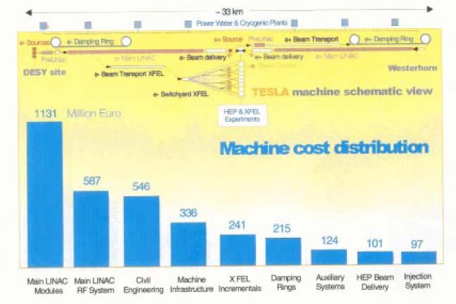
2 The RF System is a Dominant Cost Driver - As Indicated in the TTF Technical Design Report
3

4 from Barish, Monday s GDE talk Depending on your favorite number for the total estimated cost of the ILC, this percentage gives a target value

5 So, Why Is It Expensive - It s Complex!
6 One Klystron is Split and Drives Between 16 and 32 Cavities Depending on Klystron Power


7 With All the Splitting and Distributing, a Whole Lot of RF Hardware is Needed

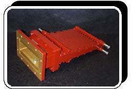
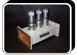
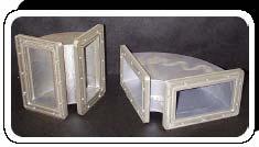
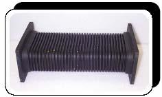
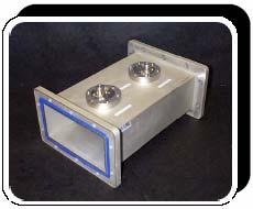
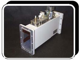
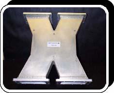
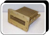
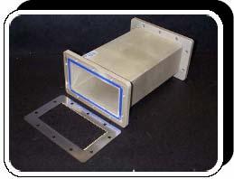
8 The RF distribution system is comprised of lots of complex parts, requiring time and effort to build
9 To Try and Better Understand the Cost Drivers in the RF Distribution System, an Assessment was Done Some costs were obtained from the TESLA Technical Design Report, others from the FNAL assessment of the TDR (which were similar) Some costs were obtained from discussions with experts (though different people often had quite different experiences) Other costs were determined by project estimating the task of building the pieces of hardware, then adjusting numbers around for interconsistency In general, the approach was to assume that more complex pieces of hardware would be more costly that simple pieces. complex: couplers, circulators, loads, hybrids, 3 stub tuners simpler: straights, H bends, flex guides (?), directional couplers Overall, at this stage, the exact estimated numbers are not as crucial as the areas they identify as major cost drivers for the overall system
10 To Give Some Idea of Numbers Some quantity numbers were taken from the FNAL Tesla Engineering Study Review
11 And costs as well
12 An Assessment of Some Relative Costs - sans Klystron and Modulator line hybrid loads (air) 6% line hybrids 8% H-plane bends 7% flexible guide sections 5% directional couplers 7% intra-cryomodule straights 2% drive hybrids 1% drive hybrid loads (air) 1% coupler HV bias supplies 1% couplers 26% 3 stub tuners 9% The assessment was done using a cost estimating exercise to determine what the relative costs of components were based on an independent evaluation of materials and effort to build components circulator loads (water) 7% circulators 20%
13 intra-cryomodule line hybrid loads straights (air) 1% line hybrids 6% drive hybrids 1% An Estimate of Some Costs - Includes Klystron and Modulator drive hybrid loads (air) 1% coupler HV bias supplies 1% 4% klystrons (should be 752) 6% WR 650 waveguide yikes! (recall the 12% number ) SRF cavities check cavities/cryomodule 8 check cavities/klystron 32 check 16 per 5 MW, 32 per 10 MW klystron peak power (MW) 10 check cryomodules 3008 THIS IS FOR THE ENTIRE ILC SYSTEM total= $3,666,988,880 H-plane bends 5% flexible guide sections 3% tional couplers 5% circulator loads (water) 5% circulators 14% 3 stub tuners 7% couplers 19% modulators 22% numbers cost/unit sub cost % of total klystrons 752 $180,000 $135,360, modulators 752 $645,000 $485,040, couplers $34,402 $827,849, stub tuners $12,103 $291,234, circulators $25,029 $602,297, circulator loads (water) $8,601 $206,962, directional couplers $8,498 $204,483, flexible guide sections $6,232 $149,954, H-plane bends $4,172 $200,765, line hybrids $10,455 $251,577, line hybrid loads (air) $7,931 $190,851, intra-cryomodule straights $2,163 $52,050, drive hybrids 1504 $10,455 $15,723, drive hybrid loads (air) 1504 $7,931 $11,928, coupler HV bias supplies $1,700 $40,908, As this was a first attempt, I assume I was being too conservative in my costing. I attempted to shoot low to hit closer to what I thought a good 12% number might be
14 A Further Estimate of Some Costs - Includes Klystron and Modulator line hybrid loads (air) 2% line hybrids 3% H-plane bends 2% flexible guide sections 3% intra-cryomodule straights 1% drive hybrids 0% drive hybrid loads (air) 0% coupler HV bias supplies 2% klystrons 10% SRF cavities check cavities/cryomodule 8 check cavities/klystron 32 check 16 per 5 MW, 32 per 10 MW klystron peak power (MW) 10 check cryomodules 3008 THIS IS TO TRY TO HIT THE 12% NUMBER THIS IS FOR THE ENTIRE ILC SYSTEM total= $1,329,987,200 target! numbers cost/unit sub cost % of total irectional couplers 3% circulator loads (water) 4% circulators 14% 3 stub tuners 2% couplers 18% modulators 36% klystrons 752 $180,000 $135,360, modulators 752 $645,000 $485,040, couplers $10,000 $240,640, stub tuners $1,000 $24,064, circulators $8,000 $192,512, circulator loads (water) $2,000 $48,128, directional couplers $1,500 $36,096, flexible guide sections $1,400 $33,689, H-plane bends $500 $24,064, line hybrids $1,500 $36,096, line hybrid loads (air) $1,250 $30,080, intra-cryomodule straights $500 $12,032, drive hybrids 1504 $1,000 $1,504, drive hybrid loads (air) 1504 $1,200 $1,804, coupler HV bias supplies $1,200 $28,876, Some of these costs appear very low to me Even with drastic cost reductions, this does not appear consistent with 12% of accepted ILC TEC
15 Thoughts on Assessments and RF Distribution Costs So Far Costs on the ILC RF distribution system will be driven up by two main factors: Very big costs on smaller numbers of items, e.g., modulators - $645,000 x 752 Very big number of moderately expensive items, e.g., couplers - 24,000 x $10,000 For some perspective, in the analysis, ILC will need ~250,000 RF plumbing parts! At an average of $1000 each, that s $250,000,000. This assessment is an attempt to start to look at high dollar items to help prioritize cost reduction efforts This also gives suggests (to me) that we had better realize some significant cost reductions due to quantity to meet some of the present cost estimates out there
US-ILC Waveguide Industrialization Study. Marc Ross, Chris Nantista and Chris Adolphsen
 US-ILC Waveguide Industrialization Study Marc Ross, Chris Nantista and Chris Adolphsen ILC Local Power Distribution System (LPDS) variable power divider, pressurizable, 0-100%, phase stable pressure window
WG2 Group Summary. Chris Adolphsen Terry Garvey Hitoshi Hayano
 WG2 Group Summary Chris Adolphsen Terry Garvey Hitoshi Hayano Linac Options Fest On Thursday afternoon, various experts summarized the linac baseline options. Although hard choices have yet to be made,
INFN School on Electron Accelerators. RF Power Sources and Distribution
 INFN School on Electron Accelerators 12-14 September 2007, INFN Sezione di Pisa Lecture 7b RF Power Sources and Distribution Carlo Pagani University of Milano INFN Milano-LASA & GDE The ILC Double Tunnel
ILC-LNF TECHNICAL NOTE
 IL-LNF EHNIAL NOE Divisione Acceleratori Frascati, July 4, 2006 Note: IL-LNF-001 RF SYSEM FOR HE IL DAMPING RINGS R. Boni, INFN-LNF, Frascati, Italy G. avallari, ERN, Geneva, Switzerland Introduction For
5 Project Costs and Schedule
 93 5 Project Costs and Schedule 5.1 Overview The cost evaluation for the integrated version of the XFEL with 30 experiments and 35 GeV beam energy as described in the TDR-2001 yielded 673 million EUR for
 STF Beta
 Oak Ridge Spallation Neutron Source Proton Power Upgrade Project and Second Target Station Project
 Oak Ridge Spallation Neutron Source Proton Power Upgrade Project and Second Target Station Project Workshop on the future and next generation capabilities of accelerator driven neutron and muon sources
XFEL High Power RF System Recent Developments
 XFEL High Power RF System Recent Developments for the XFEL RF Group Outline XFEL RF System Requirements Overview Basic Layout RF System Main Components Multibeam Klystrons Modulator RF Waveguide Distribution
Examples of Successful Collaboration Between CPI and DOE Labs. Todd Treado CPI December 2013
 Examples of Successful Collaboration Between CPI and DOE Labs Todd Treado CPI December 2013 Overview CPI has successfully collaborated with US DOE labs to develop and / or manufacture products for DOE
A New High Intensity Proton Source. The SCRF Proton Driver. (and more!) at Fermilab. July 15, Bill Foster SRF2005
 at Fermilab. July 15, Bill Foster SRF2005") The SCRF Proton Driver A New High Intensity Proton Source (and more!) at Fermilab Bill Foster SRF2005 July 15, 2005 Outline The Concept Fermilab Strategic Context Proton Driver SRF Linac Design Ferrite
The SCRF Proton Driver A New High Intensity Proton Source (and more!) at Fermilab Bill Foster SRF2005 July 15, 2005 Outline The Concept Fermilab Strategic Context Proton Driver SRF Linac Design Ferrite
Nick Walker DESY MAC
 Nick Walker DESY MAC 4.5.2006 XFEL X-Ray Free-Electron Laser DESY ILC Project Group Accelerator Experimentation Behnke, Elsen, Walker (chair) WP 15, 16 WP 4-7 Accelerator Physics and Design WP 6 High Gradient
Modulator Overview System Design vs. Tunnel Topologies. Snowmass Workshop August 16, 2005 Ray Larsen for the SLAC ILC Group
 Modulator Overview System Design vs. Tunnel Topologies Snowmass Workshop August 16, 2005 Ray Larsen for the SLAC ILC Group Outline! I. Modulator Options vs. Topologies! II. Preliminary Cost Estimates!
DEVELOPMENT OF A 10 MW SHEET BEAM KLYSTRON FOR THE ILC*
 DEVELOPMENT OF A 10 MW SHEET BEAM KLYSTRON FOR THE ILC* D. Sprehn, E. Jongewaard, A. Haase, A. Jensen, D. Martin, SLAC National Accelerator Laboratory, Menlo Park, CA 94020, U.S.A. A. Burke, SAIC, San
The European Spallation Source
 The European Spallation Source Roger Ruber Uppsala University NIKHEF industriemiddag 21 september 2011 The European Spallation Source Roger Ruber - The European Spallation Source NIKHEF, 21-Sep-2011 page
Suggested ILC Beam Parameter Range Rev. 2/28/05 Tor Raubenheimer
 The machine parameters and the luminosity goals of the ILC were discussed at the 1 st ILC Workshop. In particular, Nick Walker noted that the TESLA machine parameters had been chosen to achieve a high
Karin Rathsman. Calculations on the RF Source and Distribution
 Accelerator Division ESS AD Technical Note ESS/AD/0002 Karin Rathsman Calculations on the RF Source and Distribution 26 March 2010 Calculations on the rf source and distribution system for the ESS elliptical
L-Band RF R&D. SLAC DOE Review June 15 th, Chris Adolphsen SLAC
 L-Band RF R&D SLAC DOE Review June 15 th, 2005 Chris Adolphsen SLAC International Linear Collider (ILC) RF Unit (TESLA TDR Layout) Gradient = 23.4 MV/m Bunch Spacing = 337 ns Fill Time = 420 µs Train Length
TITLE PAGE. Title of paper: PUSH-PULL FEL, A NEW ERL CONCEPT Author: Andrew Hutton. Author Affiliation: Jefferson Lab. Requested Proceedings:
 TITLE PAGE Title of paper: PUSH-PULL FEL, A NEW ERL CONCEPT Author: Andrew Hutton Author Affiliation: Jefferson Lab Requested Proceedings: Unique Session ID: Classification Codes: Keywords: Energy Recovery,
!"!3
 Abstract A single-mode 500 MHz superconducting cavity cryomodule has been developed at Cornell for the electronpositron collider/synchrotron light source CESR. The Cornell B-cell cavity belongs to the
Next Linear Collider. The 8-Pack Project. 8-Pack Project. Four 50 MW XL4 X-band klystrons installed on the 8-Pack
 The Four 50 MW XL4 X-band klystrons installed on the 8-Pack The Demonstrate an NLC power source Two Phases: 8-Pack Phase-1 (current): Multi-moded SLED II power compression Produce NLC baseline power: 475
2 Work Package and Work Unit descriptions. 2.8 WP8: RF Systems (R. Ruber, Uppsala)
") 2 Work Package and Work Unit descriptions 2.8 WP8: RF Systems (R. Ruber, Uppsala) The RF systems work package (WP) addresses the design and development of the RF power generation, control and distribution
2 Work Package and Work Unit descriptions 2.8 WP8: RF Systems (R. Ruber, Uppsala) The RF systems work package (WP) addresses the design and development of the RF power generation, control and distribution
News from HZB / BESSY Wolfgang Anders at ESLS-RF Meeting September 2010 Trieste
 News from HZB / BESSY Wolfgang Anders at ESLS-RF Meeting September 2010 Trieste Outline Status Klystrons / IOT Modifications of transmitters New LINAC for BESSY II Status BERLinPro HoBiCaT Extension --
RF plans for ESS. Morten Jensen. ESLS-RF 2013 Berlin
 RF plans for ESS Morten Jensen ESLS-RF 2013 Berlin Overview The European Spallation Source (ESS) will house the most powerful proton linac ever built. The average beam power will be 5 MW which is five
J/NLC Progress on R1 and R2 Issues. Chris Adolphsen
 J/NLC Progress on R1 and R2 Issues Chris Adolphsen Charge to the International Linear Collider Technical Review Committee (ILC-TRC) To assess the present technical status of the four LC designs at hand,
TTF Tuner Development: Saclay and INFN-Blade
 TTF Tuner Development: Saclay and INFN-Blade Carlo Pagani INFN Milano and DESY On leave from University of Milano The TTF Saclay Tuner: Operation Principle Design by M. Maurier and P. Leconte based of
RF Power Klystrons & 20 Year Look. R. Nelson 7/15/15
 RF Power Klystrons & 20 Year Look R. Nelson 7/15/15 RF Power klystrons 8 x 13 kw klystrons Page 2 Why A klystron? Best (only) choice at the time - 1988 Easy to use: Input (drive), output (to CM), power
Pulsed Klystrons for Next Generation Neutron Sources Edward L. Eisen - CPI, Inc. Palo Alto, CA, USA
 Pulsed Klystrons for Next Generation Neutron Sources Edward L. Eisen - CPI, Inc. Palo Alto, CA, USA Abstract The U.S. Department of Energy (DOE) Office of Science has funded the construction of a new accelerator-based
Tuner, Coupler WP & specification
 03042008 GDE meeting @ Sendai Tuner, Coupler WP & specification table H. Hayano, KEK Cavity Package WP-CP1. Tuner Work Package Tuner Selection ( Saclay tuner, Brade tuner, Slide-jack tuner, Ball-screw
NSLS-II RF Systems James Rose, Radio Frequency Group Leader PAC 2011
 NSLS-II RF Systems James Rose, Radio Frequency Group Leader PAC 2011 1 BROOKHAVEN SCIENCE ASSOCIATES Introduction Linac RF cavities and klystrons Booster Cavity-Transmitter Storage Ring 500 MHz SRF cavity
The ESS Accelerator. For Norwegian Industry and Research. Oslo, 24 Sept Håkan Danared Deputy Head Accelerator Division Group Leader Beam Physics
 The ESS Accelerator For Norwegian Industry and Research Oslo, 24 Sept 2013 Håkan Danared Deputy Head Accelerator Division Group Leader Beam Physics The Hadron Intensity Frontier Courtesy of M. Seidel (PSI)
What can be learned from HERA Experience for ILC Availability
 What can be learned from HERA Experience for ILC Availability August 17, 2005 F. Willeke, DESY HERA Performance Critical Design Decisions What could be avoided if HERA would have to be built again? HERA
Evaluation of Performance, Reliability, and Risk for High Peak Power RF Sources from S-band through X-band for Advanced Accelerator Applications
 Evaluation of Performance, Reliability, and Risk for High Peak Power RF Sources from S-band through X-band for Advanced Accelerator Applications Michael V. Fazio C. Adolphsen, A. Jensen, C. Pearson, D.
IOT RF Power Sources for Pulsed and CW Linacs
 LINAC 2004 Lübeck, August 16 20, 2004 IOT RF Power Sources H. Bohlen, Y. Li, Bob Tornoe Communications & Power Industries Eimac Division, San Carlos, CA, USA Linac RF source property requirements (not
A HIGH POWER LONG PULSE HIGH EFFICIENCY MULTI BEAM KLYSTRON
 A HIGH POWER LONG PULSE HIGH EFFICIENCY MULTI BEAM KLYSTRON A.Beunas and G. Faillon Thales Electron Devices, Vélizy, France S. Choroba DESY, Hamburg, Germany Abstract THALES ELECTRON DEVICES has developed
A New 4MW LHCD System for EAST
 1 EXW/P7-29 A New 4MW LHCD System for EAST Jiafang SHAN 1), Yong YANG 1), Fukun LIU 1), Lianmin ZHAO 1) and LHCD Team 1) 1) Institute of Plasma Physics, Chinese Academy of Sciences, Hefei, China E-mail
ILC RF System R&D. Chris Adolphsen, SLAC. Section of 1.3 GHz SC Linac. June 29, 2007 PAC07 Talk FRYC01
 ILC RF System R&D Chris Adolphsen, SLAC June 29, 2007 PAC07 Talk FRYC01 Section of 1.3 GHz SC Linac ILC Main Linac RF Unit (1 of 560) RF System Gradient = 31.5 MV/m Rep Rate = 5 Hz Beam Current = 9.0 ma
RF Power Upgrade at Jefferson Lab
 RF Power Upgrade at Jefferson Lab Rick Nelson*, Andrew Kimber *nelson@jlab.org * Notice: Authored by Jefferson Science Associates, LLC under U.S. DOE Contract No. DE- AC05-06OR23177. The U.S. Government
OF THIS DOCUMENT IS W8.MTO ^ SF6
 fflgh PEAK POWER TEST OF S-BAND WAVEGUIDE SWITCHES A. Nassiri, A. Grelick, R. L. Kustom, and M. White CO/0 ^"^J} 5, t * y ^ * Advanced Photon Source, Argonne National Laboratory» \^SJ ^ ^ * **" 9700 South
Availability and Reliability Issues for the ILC
 Availability and Reliability Issues for the ILC SLAC Presented at PAC07 26 June 07 Contents Introduction and purpose of studies The availability simulation What was modeled (important assumptions) Some
Working Group 2 Introductory presentation. Convenors C. Adolphsen, T. Garvey, H. Hayano
 Working Group 2 Introductory presentation. Convenors C. Adolphsen, T. Garvey, H. Hayano Topics covered by WG2 Modulators / klystrons RF wave-guide distribution Low Level RF Beam interfaces (quadrupoles,
Upgrade of CEBAF to 12 GeV
 Upgrade of CEBAF to 12 GeV Leigh Harwood (for 12 GeV Accelerator team) Page 1 Outline Background High-level description Schedule Sub-system descriptions and status Summary Page 2 CEBAF Science Mission
ESS Linac WP8 Radio Frequency Systems and Test Facilities
 ESS Linac WP8 Radio Frequency Systems and Test Facilities ESS TAC Lund, 8 July 2010 Roger Ruber (Uppsala University) for the ESS Linac RF Team Outline Work Package description Objectives Organization Technical
Introduction: CW SRF linac types, requirements and challenges High power RF system architecture
 RF systems for CW SRF linacs S. Belomestnykh Cornell University Laboratory for Elementary-Particle Physics LINAC08, Victoria, Canada October 1, 2008 Outline L band Introduction: CW SRF linac types, requirements
IOT OPERATIONAL EXPERIENCE ON ALICE AND EMMA AT DARESBURY LABORATORY
 IOT OPERATIONAL EXPERIENCE ON ALICE AND EMMA AT DARESBURY LABORATORY A. Wheelhouse ASTeC, STFC Daresbury Laboratory ESLS XVIII Workshop, ELLETRA 25 th 26 th November 2010 Contents Brief Description ALICE
STATUS OF THE INTERNATIONAL LINEAR COLLIDER
 STATUS OF THE INTERNATIONAL LINEAR COLLIDER K. Yokoya, KEK, Tsukuba, Japan Abstract The International Linear Collider (ILC) is the nextgeneration electron-positron collider. Since the publication of the
ESS: The Machine. Bucharest, 24 April Håkan Danared Deputy Head Accelerator Division. H. Danared Industry & Partner Days Bucharest Page 1
 ESS: The Machine Bucharest, 24 April 2014 Håkan Danared Deputy Head Accelerator Division H. Danared Industry & Partner Days Bucharest Page 1 2025 ESS construction complete 2009 Decision: ESS will be built
SUMMARY OF THE ILC R&D AND DESIGN
 SUMMARY OF THE ILC R&D AND DESIGN B. C. Barish, California Institute of Technology, USA Abstract The International Linear Collider (ILC) is a linear electron-positron collider based on 1.3 GHz superconducting
The TESLA RF System. S. Choroba. for the TESLA Collaboration. DESY Notkestr. 85, D Hamburg, Germany
 The TESLA RF System S. Choroba for the TESLA Collaboration DESY Notkestr. 85, D-22603 Hamburg, Germany Abstract. The TESLA project proposed by the TESLA collaboration in 2001 is a 500 to 800GeV e+/e- linear
Commissioning of Accelerators. Dr. Marc Munoz (with the help of R. Miyamoto, C. Plostinar and M. Eshraqi)
") Commissioning of Accelerators Dr. Marc Munoz (with the help of R. Miyamoto, C. Plostinar and M. Eshraqi) www.europeanspallationsource.se 6 July, 2017 Contents General points Definition of Commissioning
Commissioning of Accelerators Dr. Marc Munoz (with the help of R. Miyamoto, C. Plostinar and M. Eshraqi) www.europeanspallationsource.se 6 July, 2017 Contents General points Definition of Commissioning
Electron linac photo-fission driver for rare isotope program at TRIUMF
 Canada s national laboratory for particle and nuclear physics Laboratoire national canadien pour la recherche en physique nucléaire et en physique des particules Electron linac photo-fission driver for
Karin Rathsman, Håkan Danared and Rihua Zeng. Report from RF Power Source Workshop
 Accelerator Division ESS AD Technical Note ESS/AD/0020 Karin Rathsman, Håkan Danared and Rihua Zeng Report from RF Power Source Workshop 10 July 2011 Report on the RF Power Source Workshop K. Rathsman,
Solid State Modulators for X-Band Accelerators
 Solid State Modulators for X-Band Accelerators John Kinross-Wright Diversified Technologies, Inc. Bedford, Massachusetts DTI X-Band Experience Developed and built two completely different NLC-class modulator
ESS Linac WP8 Radio Frequency Systems and Test Facilities
 ESS Linac WP8 Radio Frequency Systems and Test Facilities ESS/SPL Collaboration Meeting Lund, 29 June 2010 Roger Ruber (Uppsala University) for the ESS Linac RF Team ESS Linac WP8: RF Systems Outline Work
Thoughts on Project Standard in Japan
 Thoughts on Project Standard in Japan August 16, 2005 H. Hayano, KEK Thoughts on project standard in Japan Production is industry-base, almost all-case. 1. Industry makes every detail drawings. 2. (Big)
SLAC R&D Program for a Polarized RF Gun
 ILC @ SLAC R&D Program for a Polarized RF Gun SLAC-PUB-11657 January 2006 (A) J. E. CLENDENIN, A. BRACHMANN, D. H. DOWELL, E. L. GARWIN, K. IOAKEIMIDI, R. E. KIRBY, T. MARUYAMA, R. A. MILLER, C. Y. PRESCOTT,
CLIC Feasibility Demonstration at CTF3
 CLIC Feasibility Demonstration at CTF3 Roger Ruber Uppsala University, Sweden, for the CLIC/CTF3 Collaboration http://cern.ch/clic-study LINAC 10 MO303 13 Sep 2010 The Key to CLIC Efficiency NC Linac for
SRS and ERLP developments. Andrew moss
 SRS and ERLP developments Andrew moss Contents SRS Status Latest news Major faults Status Energy Recovery Linac Prototype Latest news Status of the RF system Status of the cryogenic system SRS Status Machine
Klystron Lifetime Management System
 Klystron Lifetime Management System Łukasz Butkowski Vladimir Vogel FLASH Seminar Outline 2 Introduction to KLM Protection and measurement functions Installation at Klystron test stand FPGA implementation
Experience with the Cornell ERL Injector SRF Cryomodule during High Beam Current Operation
 Experience with the Cornell ERL Injector SRF Cryomodule during High Beam Current Operation Matthias Liepe Assistant Professor of Physics Cornell University Experience with the Cornell ERL Injector SRF
DEPARTMENT OF ELECTRONICS AND COMMUNICATION ENGINEERING QUESTION BANK
 DEPARTMENT OF ELECTRONICS AND COMMUNICATION ENGINEERING QUESTION BANK SUBJECT NAME : MICROWAVE ENGINEERING UNIT I BASIC MICROWAVE COMPONENTS 1. State Faraday s rotation law. 2. State the properties of
The LEP Superconducting RF System
 The LEP Superconducting RF System K. Hübner* for the LEP RF Group CERN The basic components and the layout of the LEP rf system for the year 2000 are presented. The superconducting system consisted of
SLAC ILC Accelerator R&D Program
 SLAC ILC Accelerator R&D Program SLUO Meeting September 26 th, 2005 Tor Raubenheimer SLAC 2005 ILC Program NLC group was redirected towards ILC Developed a program aimed at the topics identified in the
RF Upgrades & Experience At JLab. Rick Nelson
 RF Upgrades & Experience At JLab Rick Nelson Outline Background: CEBAF / Jefferson Lab History, upgrade requirements & decisions Progress & problems along the way Present status Future directions & concerns
DELIVERY RECORD. Location: Ibaraki, Japan
 DELIVERY RECORD Client: Japan Atomic Energy Agency (JAEA) High Energy Accelerator Research Organization (KEK) Facility: J-PARC (Japan Proton Accelerator Research Complex) Location: Ibaraki, Japan 1 October
Present Status and Future Upgrade of KEKB Injector Linac
 Present Status and Future Upgrade of KEKB Injector Linac Kazuro Furukawa, for e /e + Linac Group Present Status Upgrade in the Near Future R&D towards SuperKEKB 1 Machine Features Present Status and Future
PoS(EPS-HEP2015)525. The RF system for FCC-ee. A. Butterworth CERN 1211 Geneva 23, Switzerland
525. The RF system for FCC-ee. A. Butterworth CERN 1211 Geneva 23, Switzerland") CERN 1211 Geneva 23, Switzerland E-mail: andrew.butterworth@cern.ch O. Brunner CERN 1211 Geneva 23, Switzerland E-mail: olivier.brunner@cern.ch R. Calaga CERN 1211 Geneva 23, Switzerland E-mail: rama.calaga@cern.ch
CERN 1211 Geneva 23, Switzerland E-mail: andrew.butterworth@cern.ch O. Brunner CERN 1211 Geneva 23, Switzerland E-mail: olivier.brunner@cern.ch R. Calaga CERN 1211 Geneva 23, Switzerland E-mail: rama.calaga@cern.ch
45 MW, 22.8 GHz Second-Harmonic Multiplier for High-Gradient Tests*
 US High Gradient Research Collaboration Workshop. SLAC, May 23-25, 2007 45 MW, 22.8 GHz Second-Harmonic Multiplier for High-Gradient Tests* V.P. Yakovlev 1, S.Yu. Kazakov 1,2, and J.L. Hirshfield 1,3 1
Behavior of the TTF2 RF Gun with long pulses and high repetition rates (TESLA note )
") Behavior of the TTF2 RF Gun with long pulses and high repetition rates (TESLA note 2003-33) DESY Hamburg TESLA COLLABORATION MEETING DESY Zeuthen, 22 Jan 2004 TTF2 RF GUN SCHEMATIC (ANSYS, F. Marhauser)
Behavior of the TTF2 RF Gun with long pulses and high repetition rates (TESLA note 2003-33) DESY Hamburg TESLA COLLABORATION MEETING DESY Zeuthen, 22 Jan 2004 TTF2 RF GUN SCHEMATIC (ANSYS, F. Marhauser)
Spear3 RF System Sam Park 11/06/2003. Spear3 RF System. High Power Components Operation and Control. RF Requirement.
 Spear3 RF System RF Requirement Overall System High Power Components Operation and Control SPEAR 3 History 1996 Low emittance lattices explored 1996 SPEAR 3 proposed 11/97 SPEAR 3 design study team formed
PROJECT DESCRIPTION. Project Name. Broader Impact. Real Time Simulator for ILC RF and CryoModules
 Project Name PROJECT DESCRIPTION Real Time Simulator for ILC RF and CryoModules Personnel and Institution(s) requesting funding Nigel Lockyer (Professor) University of Pennsylvania Anna Grassellino (1st
Accelerator Instrumentation RD. Monday, July 14, 2003 Marc Ross
 Monday, Marc Ross Linear Collider RD Most RD funds address the most serious cost driver energy The most serious impact of the late technology choice is the failure to adequately address luminosity RD issues
LLRF at SSRF. Yubin Zhao
 LLRF at SSRF Yubin Zhao 2017.10.16 contents SSRF RF operation status Proton therapy LLRF Third harmonic cavity LLRF Three LINAC LLRF Hard X FEL LLRF (future project ) Trip statistics of RF system Trip
The FLASH objective: SASE between 60 and 13 nm
 Injector beam control studies winter 2006/07 talk from E. Vogel on work performed by W. Cichalewski, C. Gerth, W. Jalmuzna,W. Koprek, F. Löhl, D. Noelle, P. Pucyk, H. Schlarb, T. Traber, E. Vogel, FLASH
14 GHz, 2.2 kw KLYSTRON GENERATOR GKP 22KP 14GHz WR62 3x400V
 14 GHz, 2.2 kw KLYSTRON GENERATOR GKP 22KP 14GHz WR62 3x400V With its characteristics of power stability independent of the load, very fast response time when pulsed (via external modulated signal), low
This paper was prepared for submittal to the Government Microcircuit Applications Conference Orlando, ET March 19-21,1996
 UCRGJC-122388 PREPRINT f Construction of an Automated Fiber Pigtailing Machine Oliver T. Strand This paper was prepared for submittal to the Government Microcircuit Applications Conference Orlando, ET
SWITCHED INFINITY: SUPPORTING AN INFINITE HD LINEUP WITH SDV
 SWITCHED INFINITY: SUPPORTING AN INFINITE HD LINEUP WITH SDV First Presented at the SCTE Cable-Tec Expo 2010 John Civiletto, Executive Director of Platform Architecture. Cox Communications Ludovic Milin,
High Brightness Injector Development and ERL Planning at Cornell. Charlie Sinclair Cornell University Laboratory for Elementary-Particle Physics
 High Brightness Injector Development and ERL Planning at Cornell Charlie Sinclair Cornell University Laboratory for Elementary-Particle Physics June 22, 2006 JLab CASA Seminar 2 Background During 2000-2001,
Basic rules for the design of RF Controls in High Intensity Proton Linacs. Particularities of proton linacs wrt electron linacs
 Basic rules Basic rules for the design of RF Controls in High Intensity Proton Linacs Particularities of proton linacs wrt electron linacs Non-zero synchronous phase needs reactive beam-loading compensation
18 GHz, 2.2 kw KLYSTRON GENERATOR GKP 24KP 18GHz WR62 3x400V
 18 GHz, 2.2 kw KLYSTRON GENERATOR GKP 24KP 18GHz WR62 3x400V With its characteristics of power stability whatever the load, very fast response time when pulsed (via external modulated signal), low ripple,
The SPL at CERN. slhc. 1. Introduction 2. Description. 3. Status of the SPL study. - Stage 1: Linac4 - Stage 2: LP-SPL - Potential further stages
 The SPL at CERN 1. Introduction 2. Description - Stage 1: Linac4 - Stage 2: LP-SPL - Potential further stages 3. Status of the SPL study slhc Roa Garoby for the SPL team 1. Introduction Motivation for
North Damping Ring RF
 North Damping Ring RF North Damping Ring RF Outline Overview High Power RF HVPS Klystron & Klystron EPICS controls Cavities & Cavity Feedback SCP diagnostics & displays FACET-specific LLRF LLRF distribution
Energy Upgrade Options for the LCLS-I Linac
 Energy Upgrade Options for the LCLS-I Linac LCLS-II TN-14-10 11/12/2014 John Sheppard, F.J. Decker, R. Iverson, H.D. Nuhn, M. Sullivan, J. Turner November 18, 2014 LCLSII-TN-14-07 LCLS 1 Linac Energy Increase
Operating Experience and Reliability Improvements on the 5 kw CW Klystron at Jefferson Lab
 Operating Experience and Reliability Improvements on the 5 kw CW Klystron at Jefferson Lab Richard Walker & Richard Nelson Jefferson Lab, Newport News VA Jefferson Lab is a $600M Department of Energy facility
TECHNICAL SPECIFICATION Multi-beam S-band Klystron type BT267
 TECHNICAL SPECIFICATION Multi-beam S-band Klystron type BT267 The company was created for the development and manufacture of precision microwave vacuum-electron-tube devices (VETD). The main product areas
Concept and R&D Plans for Project X
 Concept and R&D Plans for Project X Giorgio Apollinari 9 th ICFA Seminar SLAC, Oct. 2008 HB2008 Project X for Intensity Frontier Physics 1 Introduction Intensity Frontier: Needs and Physics Justification
9th ESLS RF Meeting September ALBA RF System. F. Perez. RF System 1/20
 ALBA RF System F. Perez RF System 1/20 ALBA Synchrotron Light Source in Barcelona (Spain) 3 GeV accelerator 30 beamlines (7 on day one) 50-50 Spanish Government Catalan Government First beam for users
High-Power Amplifier (HPA) Configuration Selection
 Configuration Selection") WHITE PAPER High-Power Amplifier (HPA) Configuration Selection by Kimberly Nevetral Abstract: High Power Amplifier configuration is one of the most important decisions for Satellite Communication (SATCOM)
WHITE PAPER High-Power Amplifier (HPA) Configuration Selection by Kimberly Nevetral Abstract: High Power Amplifier configuration is one of the most important decisions for Satellite Communication (SATCOM)
3 cerl. 3-1 cerl Overview. 3-2 High-brightness DC Photocathode Gun and Gun Test Beamline
 3 cerl 3-1 cerl Overview As described before, the aim of the cerl in the R&D program includes the development of critical components for the ERL, as well as the construction of a test accelerator. The
Improvements to the APS LINAC and SR/Booster klystron HVPS, and Accomplishments of the 352MHz RFTS
 Improvements to the APS LINAC and SR/Booster klystron HVPS, and Accomplishments of the 352MHz RFTS G. Trento Accelerator Systems Division Argonne National Laboratory Work supported by the U.S. Department
Drift Tubes as Muon Detectors for ILC
 Drift Tubes as Muon Detectors for ILC Dmitri Denisov Fermilab Major specifications for muon detectors D0 muon system tracking detectors Advantages and disadvantages of drift chambers as muon detectors
THE NEXT LINEAR COLLIDER TEST ACCELERATOR: STATUS AND RESULTS * Abstract
 SLAC PUB 7246 June 996 THE NEXT LINEAR COLLIDER TEST ACCELERATOR: STATUS AND RESULTS * Ronald D. Ruth, SLAC, Stanford, CA, USA Abstract At SLAC, we are pursuing the design of a Next Linear Collider (NLC)
Experimental Results of the Coaxial Multipactor Experiment. T.P. Graves, B. LaBombard, S.J. Wukitch, I.H. Hutchinson PSFC-MIT
 Experimental Results of the Coaxial Multipactor Experiment T.P. Graves, B. LaBombard, S.J. Wukitch, I.H. Hutchinson PSFC-MIT Summary A multipactor discharge is a resonant condition for electrons in an
Effects of the cryogenics operational conditions on the mechanical stability of the FLASH linac modules
 Effects of the cryogenics operational conditions on the mechanical stability of the FLASH linac modules Ramila Amirikas, Alessandro Bertolini, Jürgen Eschke, Mark Lomperski XFEL Module Meeting, January
Studies on an S-band bunching system with hybrid buncher
 Submitted to Chinese Physics C Studies on an S-band bunching system with hybrid buncher PEI Shi-Lun( 裴士伦 ) 1) XIAO Ou-Zheng( 肖欧正 ) Institute of High Energy Physics, Chinese Academy of Sciences, Beijing
KEKB INJECTOR LINAC AND UPGRADE FOR SUPERKEKB
 KEKB INJECTOR LINAC AND UPGRADE FOR SUPERKEKB S. Michizono for the KEK electron/positron Injector Linac and the Linac Commissioning Group KEK KEKB injector linac Brief history of the KEK electron linac
NLC - The Next Linear Collider Project NLC R&D. D. L. Burke. DOE Annual Program Review SLAC April 9-11, 2003
 DOE Annual Program Review SLAC April 9-11, 2003 NLC Activities for the Past Year Accelerator Design centered around ILC-TRC studies. Technology R&D focused on the RF R&D. Modulator, klystron, SLED-II,
Report on the LCLS Injector Technical Review
 Report on the LCLS Injector Technical Review Stanford Linear Accelerator Center November 3&4, 2003 Committee Members Prof. Patrick G. O Shea, Chair, University of Maryland Dr. Eric Colby, Stanford Linear
UNIT-3 Part A. 2. What is radio sonde? [ N/D-16]
![UNIT-3 Part A. 2. What is radio sonde? [ N/D-16]](/thumbs/88/116973079.jpg "UNIT-3 Part A. 2. What is radio sonde? [ N/D-16]") UNIT-3 Part A 1. What is CFAR loss? [ N/D-16] Constant false alarm rate (CFAR) is a property of threshold or gain control devices that maintain an approximately constant rate of false target detections
UNIT-3 Part A 1. What is CFAR loss? [ N/D-16] Constant false alarm rate (CFAR) is a property of threshold or gain control devices that maintain an approximately constant rate of false target detections
ARIEL Buildings Construction and Electron Linac Photo-Fission Driver for the Rare Isotope Program at TRIUMF
 Canada s national laboratory for particle and nuclear physics Laboratoire national canadien pour la recherche en physique nucléaire et en physique des particules ARIEL Buildings Construction and Electron
The DTH teleport - challenges and opportunities
 ...DTH Broadcasting Photo couretsy Prasit Rodphan/Shutterstock The DTH teleport - challenges and opportunities DTH broadcasting has traditionally been one of the most stable and safe market segments for